Ni-Al-Mo Single Crystal Rafting Studies
22
Shuwei Ma, Tresa.M.Pollock The University of Michigan, Ann Arbor, MI Ni-Al-Mo Single Crystal Rafting Studies MEANS Group Meeting, Columbus, OH April, 4, 2007
-
Upload
shelly-mccullough -
Category
Documents
-
view
37 -
download
1
description
Ni-Al-Mo Single Crystal Rafting Studies. Shuwei Ma, Tresa.M.Pollock The University of Michigan, Ann Arbor, MI. MEANS Group Meeting, Columbus, OH April, 4, 2007. Previous Models of Rafting. Elastic model. - PowerPoint PPT Presentation
Transcript of Ni-Al-Mo Single Crystal Rafting Studies
Shuwei Ma, Tresa.M.Pollock
The University of Michigan, Ann Arbor, MI
Ni-Al-Mo Single Crystal Rafting Studies
MEANS Group Meeting, Columbus, OHApril, 4, 2007
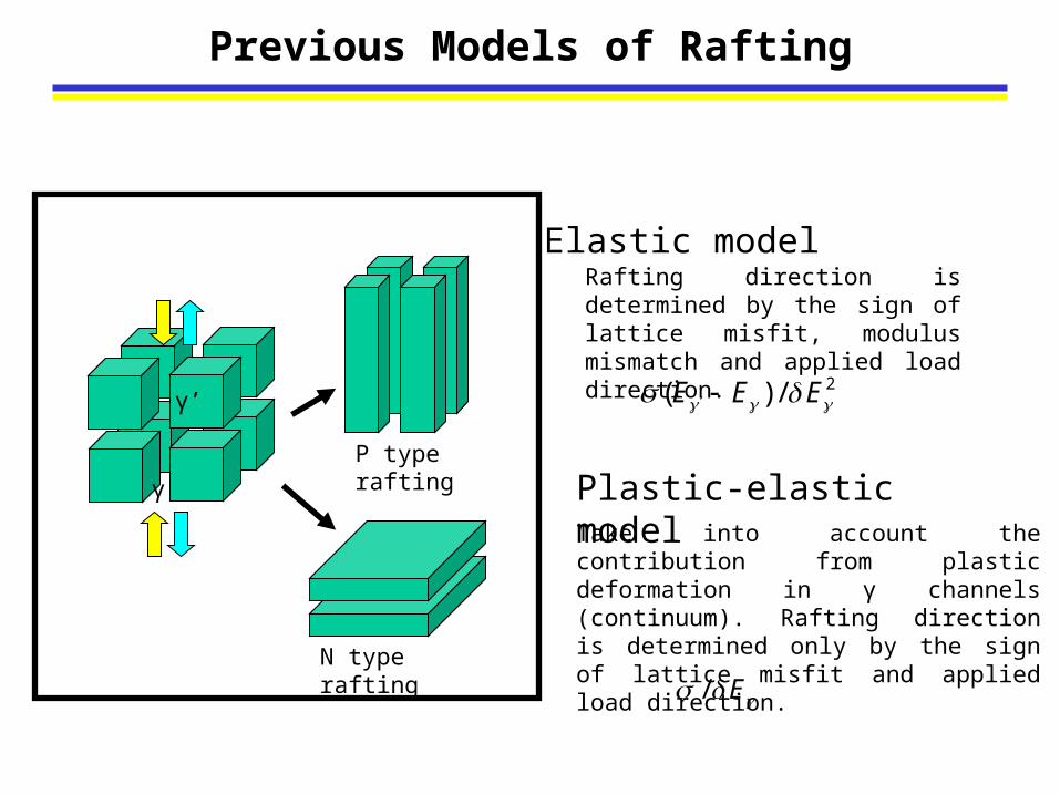
Elastic model
Plastic-elastic model
Rafting direction is determined by the sign of lattice misfit, modulus mismatch and applied load direction.
Take into account the contribution from plastic deformation in γ channels (continuum). Rafting direction is determined only by the sign of lattice misfit and applied load direction.
P type rafting
N type rafting
γ’
γ
/ E
2( ) /E E E
Previous Models of Rafting

Accounting for Local Stress Fields with Phase Field Model
External applied stress
Dislocationconfiguration Microstructure
StressField
Misfit stressDislocation stress
Dislocation movement
Microstructureevolution
Initial channel filling and relaxation: PF dislocation model
Rafting: PF binary diffusion model
)( 321
Stress due to
modulus mismatch Modulus mismatch between /’
Michael Mills’s plot
Phase field modeling was applied to evaluate elastic and plastic driving force in the Ni-Al-Mo system.
Objective
Provide a complete experimental data set in model Ni-Al-Mo single crystals for phase field modeling.
This information includes:
1. Misfit (sign and magnitude)2. Plastic strain processes in matrix3. Elastic modulus4. Diffusion5. Rafting kinetics
References
1. M.Fahrmann, W.Hermann, E, Fahrmann, A.Boegli, T.M.Pollock. Materials Science and Engineering A260 (1999) pp.212-221.
2. O.Paris, M.Fahrmann, E.Fahrmann, T.M.Pollock and P.Fratzl. Acta mater. Vol.45, No.3, 1997, pp.1085-1097.
3. M.Fahrmann, E.Fahrmann, O.Paris, P.Fratzl, and T.M.Pollock. Superalloy 1996, pp.191-200.
4. M.Fahrmann, P.Fratzl, O.Paris, E.Fahrmann and W.C.Johnson. Acta Metall.Mater, Vol.43, No.3, pp.1007-1022.
5. M.Fahrmann, E.Fahrmann, T.M.Pollock, W.C.Johnson. Metallurgical and materials Transactions A. pp.1943-1945.
Many properties have already been measured in a large set of Ni-Al-Mo single crystals
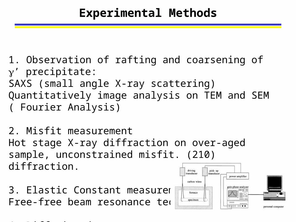
Experimental Methods
1. Observation of rafting and coarsening of ’ precipitate: SAXS (small angle X-ray scattering)Quantitatively image analysis on TEM and SEM ( Fourier Analysis)
2. Misfit measurementHot stage X-ray diffraction on over-aged sample, unconstrained misfit. (210) diffraction.
3. Elastic Constant measurementFree-free beam resonance technique.
4. Diffusion data
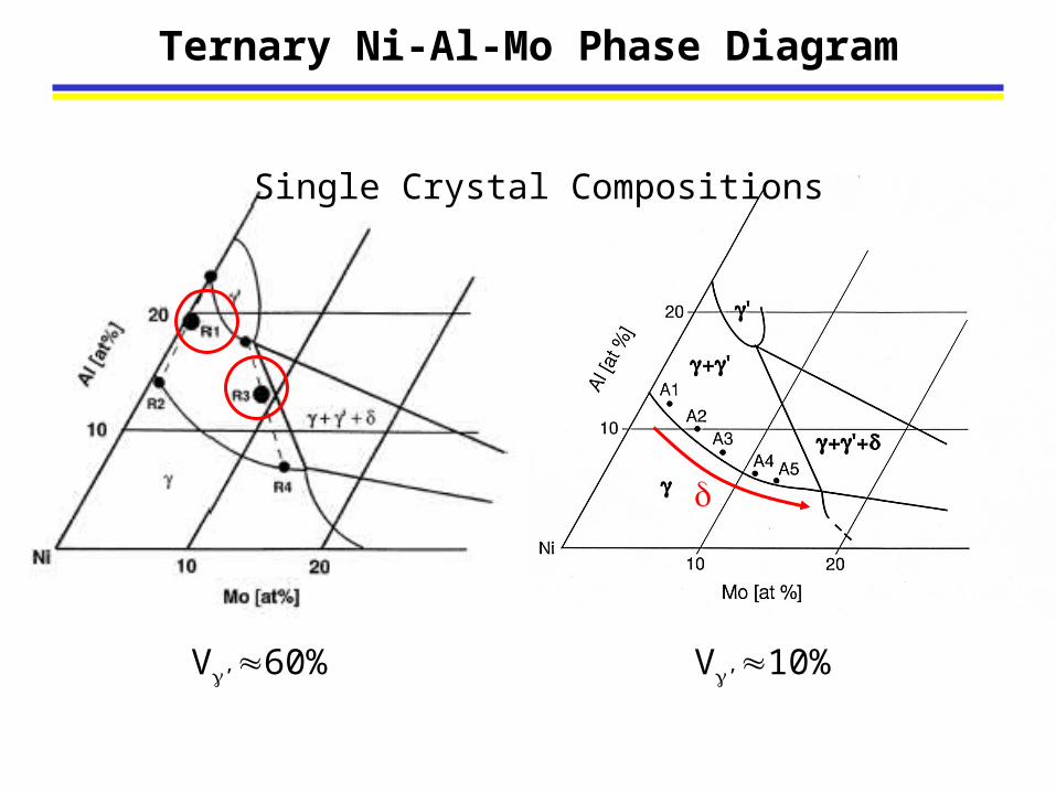
Ternary Ni-Al-Mo Phase Diagram
V’60% V’10%
Single Crystal Compositions
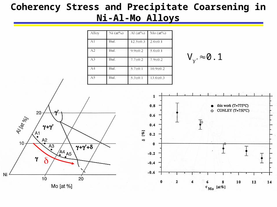
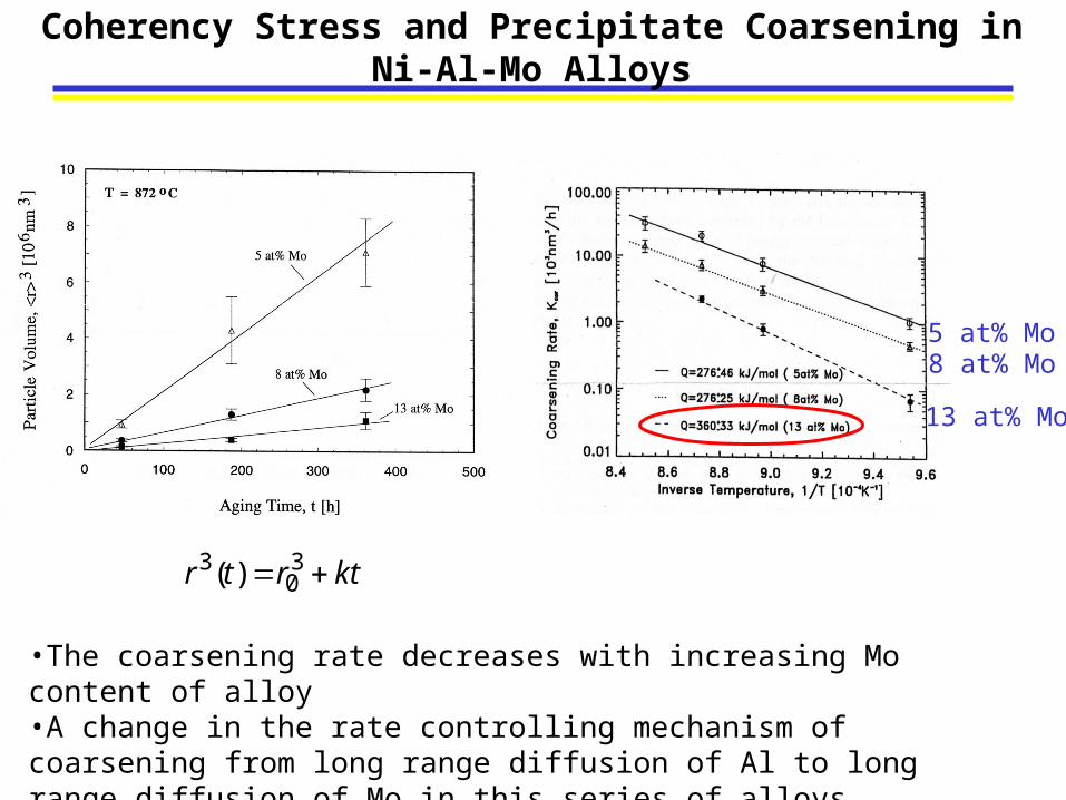
Coherency Stress and Precipitate Coarsening in Ni-Al-Mo Alloys
V’0.1
Coherency Stress and Precipitate Coarsening in Ni-Al-Mo Alloys
•The coarsening rate decreases with increasing Mo content of alloy •A change in the rate controlling mechanism of coarsening from long range diffusion of Al to long range diffusion of Mo in this series of alloys.
ktrtr 30
3 )(
13 at% Mo
8 at% Mo5 at% Mo
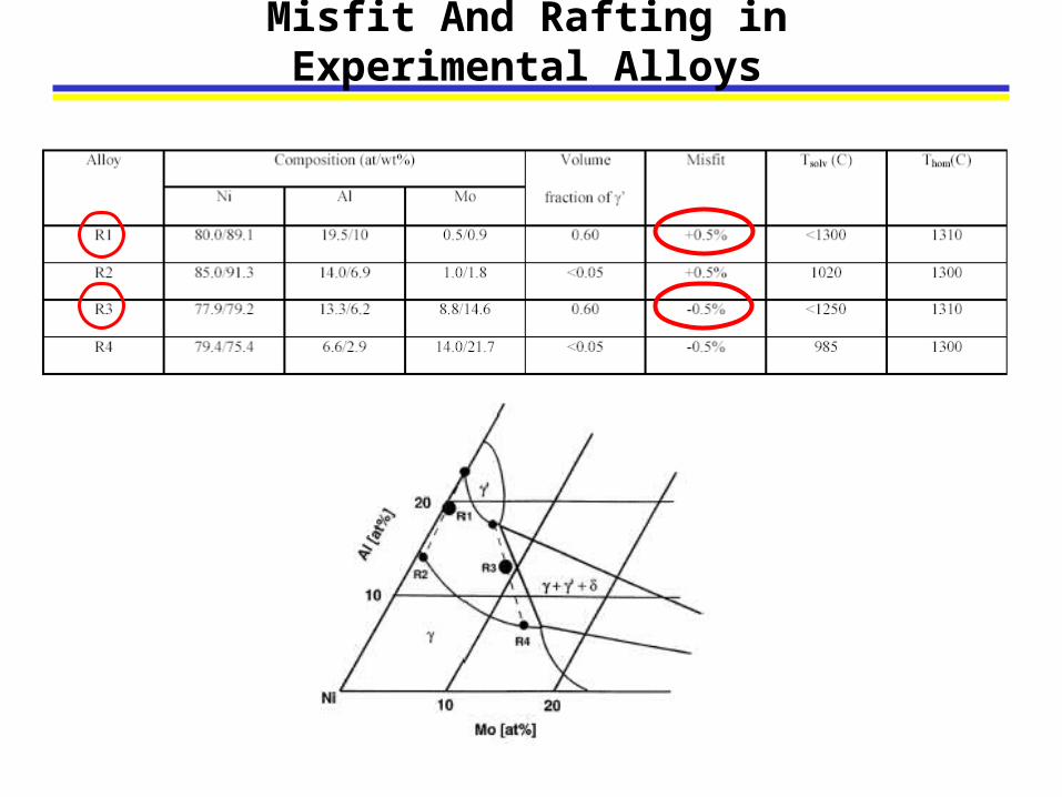
Misfit And Rafting in Experimental Alloys
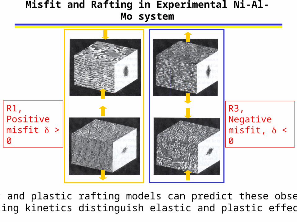
Misfit and Rafting in Experimental Ni-Al-Mo system
R1, Positive misfit > 0
R3, Negative misfit, < 0
• Elastic and plastic rafting models can predict these observation.• Do rafting kinetics distinguish elastic and plastic effects?
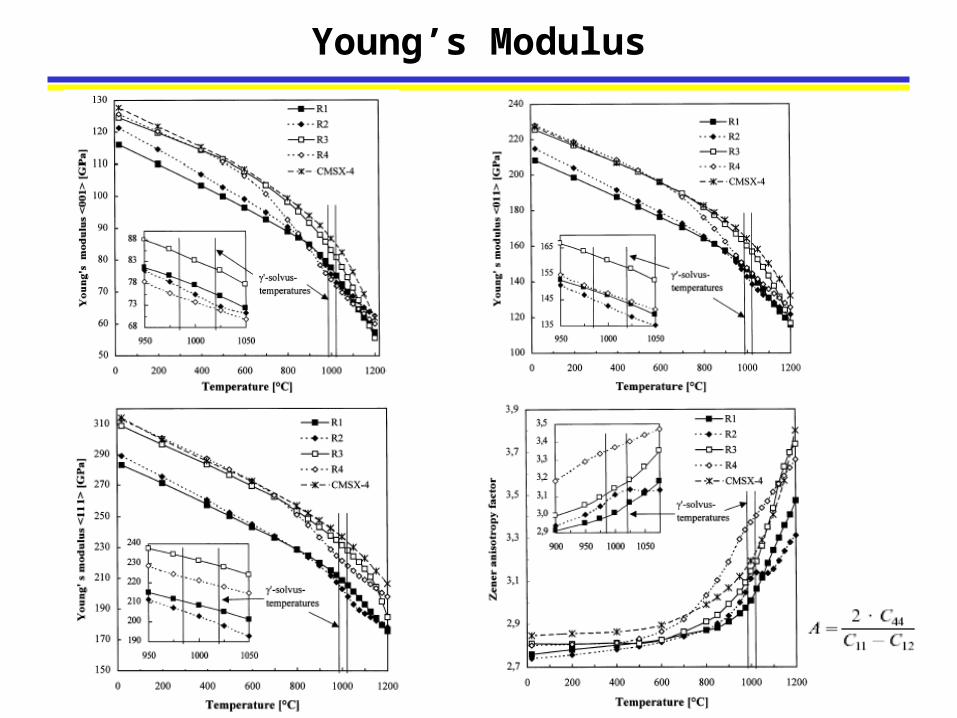
Young’s Modulus
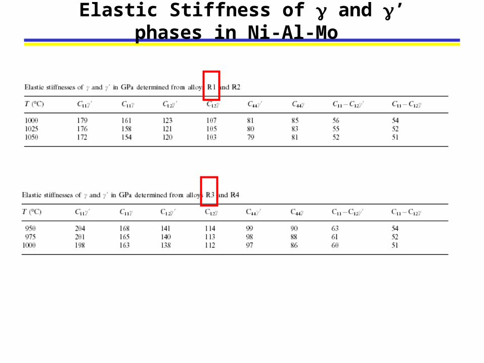
Elastic Stiffness of and ’ phases in Ni-Al-Mo
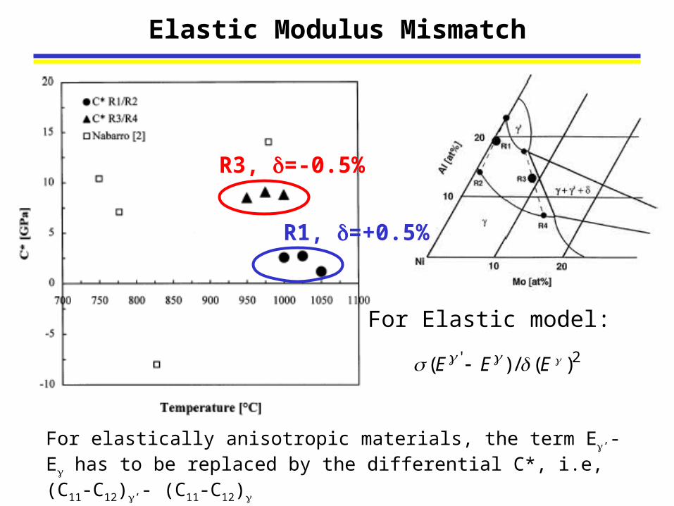
Elastic Modulus Mismatch
R3, =-0.5%
R1, =+0.5%
For elastically anisotropic materials, the term E’-E has to be replaced by the differential C*, i.e, (C11-C12)’- (C11-C12)
For Elastic model:
2' )(/)( EEE
-5 0 5 10 15 20 25 30 35 40
1
2
3
4
5
6 Fully rafted
Asp
ect
Ra
tio
Creep Time (hrs)
R3, Ni-13.3Al-8.8Mo (at%)misfit -0.5%, (Fahrmana)
R1, Ni-19.5Al-0.5Mo (at%)Misfit +0.5%, (Ma)
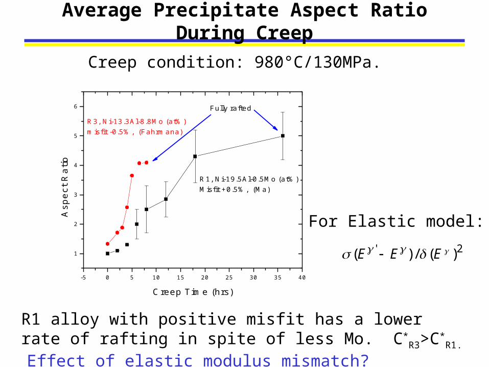
Average Precipitate Aspect Ratio During Creep
R1 alloy with positive misfit has a lower rate of rafting in spite of less Mo. C*
R3>C*R1. Effect of elastic modulus mismatch?
Creep condition: 980°C/130MPa.
For Elastic model:
2' )(/)( EEE
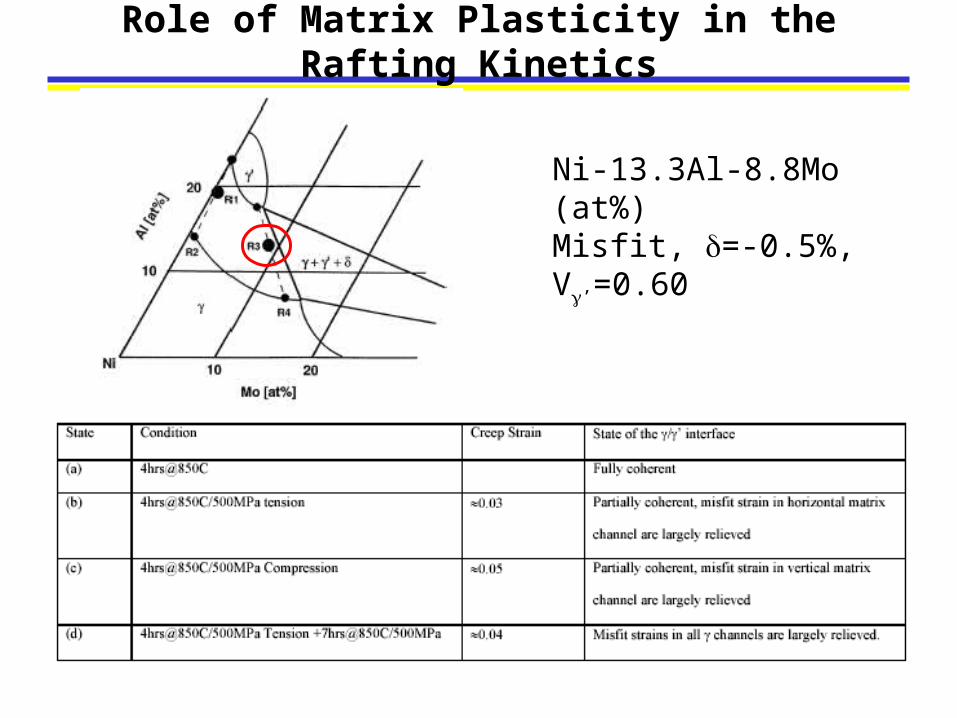
Role of Matrix Plasticity in the Rafting Kinetics
Ni-13.3Al-8.8Mo (at%)Misfit, =-0.5%,V’=0.60
Kinetics and the driving force of rafting are greatly affected by the state of the /’ interfaces.
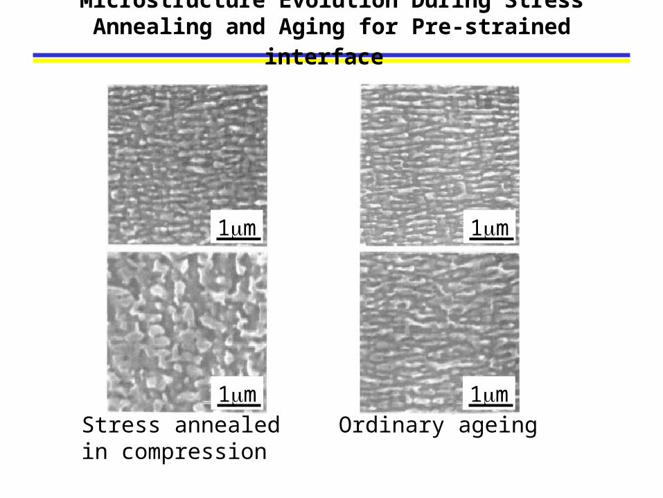
Microstructure Evolution During Stress Annealing and Aging for Pre-strained interface
•The microstructure in samples pre-strained in tension or compression rafted during subsequent aging in a direction as if the former load was still present, whereas a sample with isotropically relaxed interfaces did not show directional coarsening;
•The microstructure in a sample pre-strained in tension rafted under an applied compressive stress initially in a direction opposite to what is generally observed in compression for this alloy.
Suggestions
• Channel dislocations and modulus mismatch could both affect the rafting. This may be reflected in differences in rafting kinetics.
• It is necessary to combine channel dislocations and modulus mismatch to evaluate their relative contributions via phase field modeling.
• Does phase field modeling have sufficient fidelity to evaluate elastic + plastic driving force in the Ni-Al-Mo system?

THANK YOU!
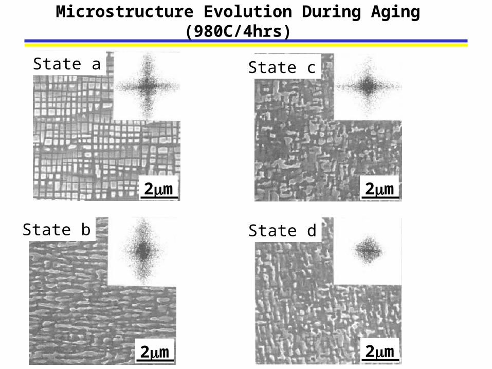
Microstructure Evolution During Aging (980C/4hrs)
State b
2m
State d
2m
State c
2m
State a
2m
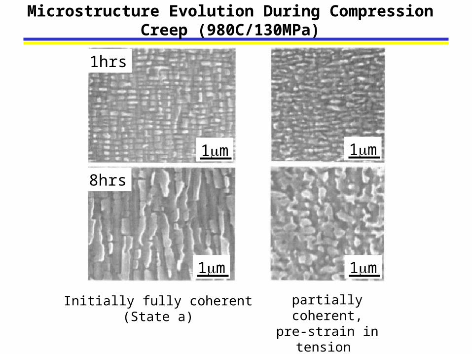
Microstructure Evolution During Compression Creep (980C/130MPa)
1hrs
8hrs
1m
1m 1m
1m
Initially fully coherent(State a)
partially coherent,pre-strain in tension
State b
1m
1m 1m
1m
Microstructure Evolution During Stress Annealing and Aging for Pre-strained interface
Stress annealed in compression
Ordinary ageing