NI 449x Calibration Procedure - National Instruments quantity 16 NI PXIe-4492: quantity 8 Pomona...
21
NI 449x Calibration Procedure This document contains information about calibrating the National Instruments 449x devices. For more information about calibration, visit ni.com/calibration. Contents Software Requirements............................................................................................................. 1 Documentation Requirements .................................................................................................. 2 Calibration Interval ................................................................................................................... 2 Test Equipment ......................................................................................................................... 3 Test Conditions ......................................................................................................................... 4 Calibration Procedures ............................................................................................................. 5 Initial Setup....................................................................................................................... 5 Self-Calibration ................................................................................................................ 5 Verification ....................................................................................................................... 5 Analog Input Performance Verification ................................................................... 6 AI Offset Verification....................................................................................... 6 AI AC Coupled Gain Accuracy Verification ................................................... 8 AI Flatness Verification.................................................................................... 10 AI DC Coupled Gain Accuracy Verification ................................................... 12 Timebase Frequency Accuracy Verification (Optional) .......................................... 14 Adjustment........................................................................................................................ 15 Analog Input Adjustment for NI 4495/4496/4498 Devices ..................................... 15 Analog Input Adjustment for NI 4492/4497/4499 Devices ..................................... 17 Updating the Calibration Date and Time without Performing Adjustment.............. 20 Where to Go for Support .......................................................................................................... 21 Software Requirements Calibrating the NI 4492/4497/4499 requires NI-DAQmx 9.2 or later. Calibrating the NI 4495/4496/4498 requires NI-DAQmx 8.8 or later. You can download the NI-DAQmx driver from ni.com/downloads. NI-DAQmx supports Self-Calibration and External Calibration in several programming language application development environments (ADEs). When you install NI-DAQmx, you only need to install support for the ADE that you intend to use. ni.com/manuals Deutsch Français
Transcript of NI 449x Calibration Procedure - National Instruments quantity 16 NI PXIe-4492: quantity 8 Pomona...
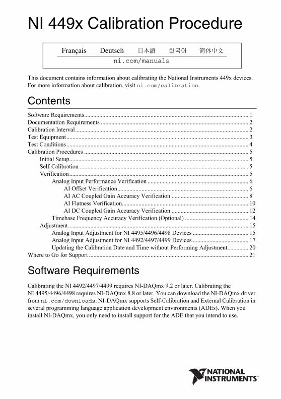
NI 449x Calibration Procedure
This document contains information about calibrating the National Instruments 449x devices. For more information about calibration, visit ni.com/calibration.
ContentsSoftware Requirements............................................................................................................. 1Documentation Requirements .................................................................................................. 2Calibration Interval................................................................................................................... 2Test Equipment......................................................................................................................... 3Test Conditions......................................................................................................................... 4Calibration Procedures ............................................................................................................. 5
Initial Setup....................................................................................................................... 5Self-Calibration ................................................................................................................ 5Verification....................................................................................................................... 5
Analog Input Performance Verification ................................................................... 6AI Offset Verification....................................................................................... 6AI AC Coupled Gain Accuracy Verification ................................................... 8AI Flatness Verification.................................................................................... 10AI DC Coupled Gain Accuracy Verification ................................................... 12
Timebase Frequency Accuracy Verification (Optional) .......................................... 14Adjustment........................................................................................................................ 15
Analog Input Adjustment for NI 4495/4496/4498 Devices ..................................... 15Analog Input Adjustment for NI 4492/4497/4499 Devices ..................................... 17Updating the Calibration Date and Time without Performing Adjustment.............. 20
Where to Go for Support .......................................................................................................... 21
Software RequirementsCalibrating the NI 4492/4497/4499 requires NI-DAQmx 9.2 or later. Calibrating the NI 4495/4496/4498 requires NI-DAQmx 8.8 or later. You can download the NI-DAQmx driver from ni.com/downloads. NI-DAQmx supports Self-Calibration and External Calibration in several programming language application development environments (ADEs). When you install NI-DAQmx, you only need to install support for the ADE that you intend to use.
ni.com/manuals
DeutschFrançais
2 | ni.com | NI 449x Calibration Procedure
Documentation RequirementsFor information about NI-DAQmx and the NI 449x, you can consult the following documents:
• DAQ Getting Started guides—provide instructions for installing and configuring NI 449x devices.
• NI-DAQmx C Reference Help—contains the C reference and general information about measurement concepts.
• NI 449x Specifications—includes detailed information about NI 449x devices and provides the published specification values for the NI 449x. Refer to the most recent NI 449x Specifications online at ni.com/manuals.
• NI-DAQmx Help—includes information about creating applications that use NI-DAQmx.
The DAQ Getting Started guides, NI-DAQmx C Reference Help, and NI-DAQmx Help are installed with NI-DAQmx. You can also download the latest versions from the NI website at ni.com/manuals.
Calibration IntervalNational Instruments recommends an external calibration interval of one year for the NI 449x. Additionally, self-calibration can be performed as desired, but is recommended when the operating temperature exceeds 5 °C from the operating temperature of the previous calibration. This temperature can be queried from the module upon command. Adjust the recommended calibration interval based on the measurement accuracy demands of your application.
NI 449x Calibration Procedure | © National Instruments | 3
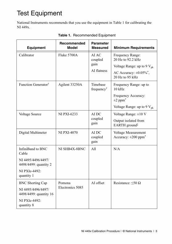
Test EquipmentNational Instruments recommends that you use the equipment in Table 1 for calibrating the NI 449x.
Table 1. Recommended Equipment
EquipmentRecommended
ModelParameter Measured Minimum Requirements
Calibrator Fluke 5700A AI AC coupled gain
AI flatness
Frequency Range: 20 Hz to 92.2 kHz
Voltage Range: up to 9 Vpk
AC Accuracy: ±0.05%*, 20 Hz to 95 kHz
Function Generator† Agilent 33250A Timebase frequency†
Frequency Range: up to 10 kHz
Frequency Accuracy: ±2 ppm*
Voltage Range: up to 9 Vpk
Voltage Source NI PXI-6233 AI DC coupled gain
Voltage Range: ±10 V
Output isolated from EARTH ground‡
Digital Multimeter NI PXI-4070 AI DC coupled gain
Voltage Measurement Accuracy: ±200 ppm*
InfiniBand to BNC Cable
NI 4495/4496/4497/4498/4499: quantity 2
NI PXIe-4492: quantity 1
NI SHB4X-8BNC All N/A
BNC Shorting Cap
NI 4495/4496/4497/4498/4499: quantity 16
NI PXIe-4492: quantity 8
Pomona Electronics 5085
AI offset Resistance: ≤50 Ω
4 | ni.com | NI 449x Calibration Procedure
If the recommended equipment is not available, select a substitute calibration standard that meets the given specifications.
Test ConditionsThe following setup and environmental conditions are required to ensure the NI 449x meets published specifications:
• Keep connections to the NI 449x as short as possible. Long cables and wires act as antennae, picking up extra noise that can affect measurements.
• Use the InfiniBand to BNC cable to connect signals to the NI 449x.
• Keep relative humidity between 10% and 80%, noncondensing, or consult the device documentation for the optimum relative humidity.
• Maintain the ambient temperature between 18 °C and 28 °C, or refer to the device specifications for the optimum temperature range.
• Allow a warm-up time of at least 15 minutes to ensure that the measurement circuitry is at a stable operating temperature.
• Allow a warm-up time for all of the instruments and equipment according to the manufacturer instructions.
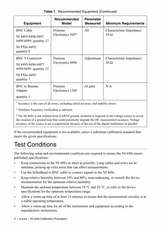
BNC Cable
NI 4495/4496/4497/4498/4499: quantity 17
NI PXIe-4492: quantity 9
Pomona Electronics 5697
All Characteristic Impedance: 50 Ω
BNC T-Connector
NI 4495/4496/4497/4498/4499: quantity 15
NI PXIe-4492: quantity 7
Pomona Electronics 4896
Adjustment Characteristic Impedance: 50 Ω
BNC to Banana Adapter
quantity 1
Pomona Electronics 1269
AI gain N/A
* Accuracy is the sum of all errors, including initial accuracy and stability errors.
† Timebase frequency verification is optional.
‡ The NI 449x is not isolated from EARTH ground. Isolation is required in the voltage source to avoid the creation of a ground loop that could potentially degrade the DC measurement accuracy. Voltage accuracy of the source is not a requirement because of the use of the digital multimeter in parallel.
Table 1. Recommended Equipment (Continued)
EquipmentRecommended
ModelParameter Measured Minimum Requirements
NI 449x Calibration Procedure | © National Instruments | 5
Calibration ProceduresThe calibration process includes the following steps:
1. Initial Setup—Install the device and configure it in Measurement & Automation Explorer (MAX).
2. Self-Calibration—Adjust the self-calibration constants of the device.
3. Verification—Verify the existing operation of the device. This step confirms whether the device is operating within the published specifications prior to adjustment.
4. Adjustment—Adjust the calibration constants of the device. The adjustment procedure automatically stores the calibration date on the EEPROM.
5. Reverification—Repeat the verification procedure to ensure that the device is operating within the published specifications after adjustment.
These procedures are described in more detail in the following sections.
Initial SetupRefer to the DAQ Getting Started guides for information about how to install the software and hardware and how to configure the device in MAX.
Self-CalibrationThe NI 449x includes precise internal circuits and references used during self-calibration to adjust for any errors caused by short-term fluctuations in the environment. Self-calibration does not require external signal connections.
Note Allow a 15 minute warm-up period before you begin self-calibration.
Initiate self-calibration from MAX. To initiate self-calibration, complete the following steps:
1. Launch MAX.
2. Select My System»Devices and Interfaces.
3. Select the device that you want to self-calibrate.
4. Initiate self-calibration in one of the following ways:
• Click Self-Calibrate in the upper right corner of the window.
• Right-click the device name under Devices and Interfaces, and select Self-Calibrate from the drop-down menu.
VerificationThis section provides instructions for verifying the NI 449x specifications. By completing this procedure, you can see how device accuracy has drifted over time, which helps you determine the appropriate calibration interval for your application.
Note Test limits in Tables 3 through 8, and Tables 13 through 15 are based upon the May 2012 edition of the NI 449x Specifications. Refer to the most recent NI 449x Specifications online at ni.com/manuals.
6 | ni.com | NI 449x Calibration Procedure
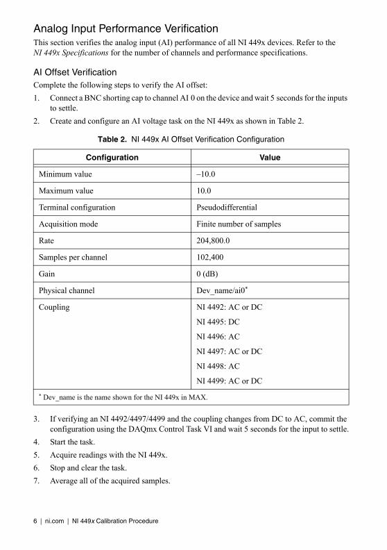
Analog Input Performance VerificationThis section verifies the analog input (AI) performance of all NI 449x devices. Refer to the NI 449x Specifications for the number of channels and performance specifications.
AI Offset VerificationComplete the following steps to verify the AI offset:
1. Connect a BNC shorting cap to channel AI 0 on the device and wait 5 seconds for the inputs to settle.
2. Create and configure an AI voltage task on the NI 449x as shown in Table 2.
3. If verifying an NI 4492/4497/4499 and the coupling changes from DC to AC, commit the configuration using the DAQmx Control Task VI and wait 5 seconds for the input to settle.
4. Start the task.
5. Acquire readings with the NI 449x.
6. Stop and clear the task.
7. Average all of the acquired samples.
Table 2. NI 449x AI Offset Verification Configuration
Configuration Value
Minimum value –10.0
Maximum value 10.0
Terminal configuration Pseudodifferential
Acquisition mode Finite number of samples
Rate 204,800.0
Samples per channel 102,400
Gain 0 (dB)
Physical channel Dev_name/ai0*
Coupling NI 4492: AC or DC
NI 4495: DC
NI 4496: AC
NI 4497: AC or DC
NI 4498: AC
NI 4499: AC or DC
* Dev_name is the name shown for the NI 449x in MAX.
NI 449x Calibration Procedure | © National Instruments | 7
If verifying an NI 4496/4498, compare this value to the appropriate limits in Table 3. The average is the offset for channel AI 0 at the 0 dB gain setting.
If verifying an NI 4495, compare this value to the limits in Table 4. The average is the offset for channel AI 0 at the 0 dB gain setting.
If verifying an NI 4492/4497/4499, compare this value to the appropriate limits in Table 5. The average is the offset for channel AI 0 at the 0 dB gain setting, at the 204.8 kS/s sample rate, in the selected coupling mode.
8. Repeat steps 2 through 7 for each gain setting that your device supports. Refer to Table 6 for the gain settings supported by NI 449x devices. When performing step 2, adjust the gain parameter appropriately.
Table 3. AI Offset Limits for NI 4496/4498
As Found Test Limit As Left Test Limit
Min (mV) Max (mV) Min (mV) Max (mV)
–2 2 –0.5 0.5
Table 4. AI Offset Limits for NI 4495
As Found Test Limit As Left Test Limit
Min (mV) Max (mV) Min (mV) Max (mV)
–0.5 0.5 –0.25 0.25
Table 5. AI Offset Limits for NI 4492/4497/4499
Coupling
As Found Test Limit As Left Test Limit
Min (mV) Max (mV) Min (mV) Max (mV)
AC –10 10 –0.5 0.5
DC –0.5 0.5 –0.25 0.25
Table 6. Supported Gain Settings
Device Gain Settings
NI 4492
0 dB, 20 dBNI 4495
NI 4496
NI 4497
NI 44980 dB, 10 dB, 20 dB, 30 dB
NI 4499
8 | ni.com | NI 449x Calibration Procedure
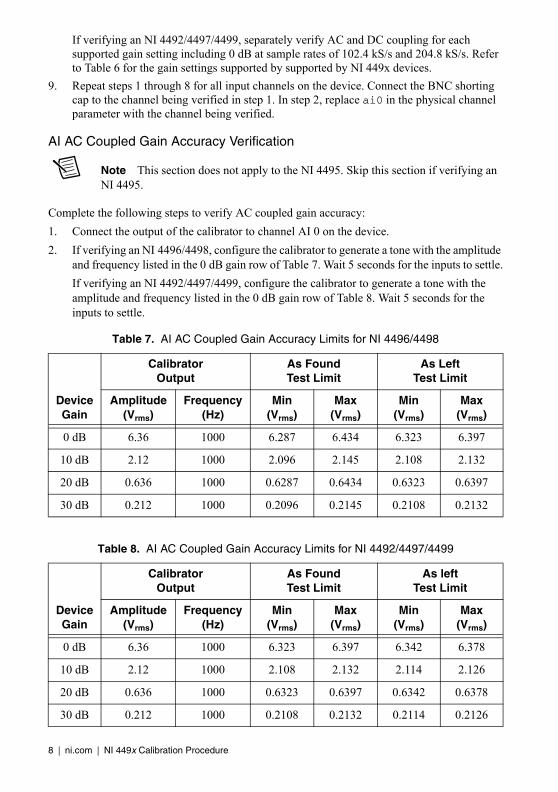
If verifying an NI 4492/4497/4499, separately verify AC and DC coupling for each supported gain setting including 0 dB at sample rates of 102.4 kS/s and 204.8 kS/s. Refer to Table 6 for the gain settings supported by supported by NI 449x devices.
9. Repeat steps 1 through 8 for all input channels on the device. Connect the BNC shorting cap to the channel being verified in step 1. In step 2, replace ai0 in the physical channel parameter with the channel being verified.
AI AC Coupled Gain Accuracy Verification
Note This section does not apply to the NI 4495. Skip this section if verifying an NI 4495.
Complete the following steps to verify AC coupled gain accuracy:
1. Connect the output of the calibrator to channel AI 0 on the device.
2. If verifying an NI 4496/4498, configure the calibrator to generate a tone with the amplitude and frequency listed in the 0 dB gain row of Table 7. Wait 5 seconds for the inputs to settle.
If verifying an NI 4492/4497/4499, configure the calibrator to generate a tone with the amplitude and frequency listed in the 0 dB gain row of Table 8. Wait 5 seconds for the inputs to settle.
Table 7. AI AC Coupled Gain Accuracy Limits for NI 4496/4498
Device Gain
CalibratorOutput
As FoundTest Limit
As LeftTest Limit
Amplitude (Vrms)
Frequency (Hz)
Min(Vrms)
Max(Vrms)
Min(Vrms)
Max(Vrms)
0 dB 6.36 1000 6.287 6.434 6.323 6.397
10 dB 2.12 1000 2.096 2.145 2.108 2.132
20 dB 0.636 1000 0.6287 0.6434 0.6323 0.6397
30 dB 0.212 1000 0.2096 0.2145 0.2108 0.2132
Table 8. AI AC Coupled Gain Accuracy Limits for NI 4492/4497/4499
Device Gain
CalibratorOutput
As FoundTest Limit
As leftTest Limit
Amplitude (Vrms)
Frequency (Hz)
Min(Vrms)
Max(Vrms)
Min(Vrms)
Max(Vrms)
0 dB 6.36 1000 6.323 6.397 6.342 6.378
10 dB 2.12 1000 2.108 2.132 2.114 2.126
20 dB 0.636 1000 0.6323 0.6397 0.6342 0.6378
30 dB 0.212 1000 0.2108 0.2132 0.2114 0.2126
NI 449x Calibration Procedure | © National Instruments | 9
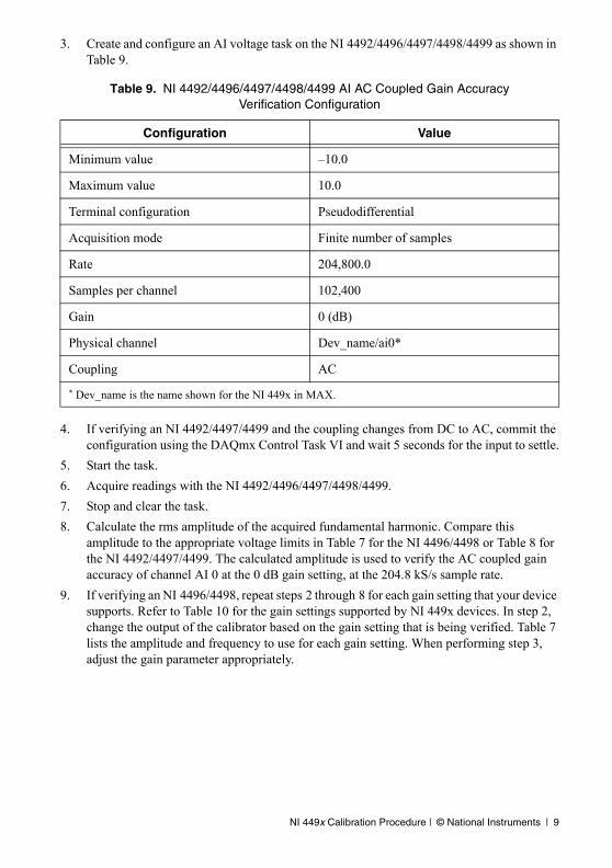
3. Create and configure an AI voltage task on the NI 4492/4496/4497/4498/4499 as shown in Table 9.
4. If verifying an NI 4492/4497/4499 and the coupling changes from DC to AC, commit the configuration using the DAQmx Control Task VI and wait 5 seconds for the input to settle.
5. Start the task.
6. Acquire readings with the NI 4492/4496/4497/4498/4499.
7. Stop and clear the task.
8. Calculate the rms amplitude of the acquired fundamental harmonic. Compare this amplitude to the appropriate voltage limits in Table 7 for the NI 4496/4498 or Table 8 for the NI 4492/4497/4499. The calculated amplitude is used to verify the AC coupled gain accuracy of channel AI 0 at the 0 dB gain setting, at the 204.8 kS/s sample rate.
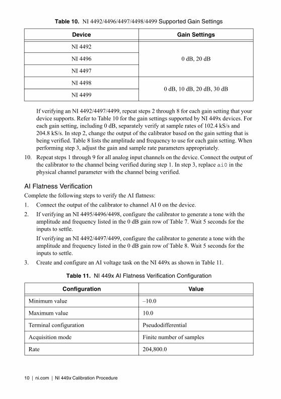
9. If verifying an NI 4496/4498, repeat steps 2 through 8 for each gain setting that your device supports. Refer to Table 10 for the gain settings supported by NI 449x devices. In step 2, change the output of the calibrator based on the gain setting that is being verified. Table 7 lists the amplitude and frequency to use for each gain setting. When performing step 3, adjust the gain parameter appropriately.
Table 9. NI 4492/4496/4497/4498/4499 AI AC Coupled Gain Accuracy Verification Configuration
Configuration Value
Minimum value –10.0
Maximum value 10.0
Terminal configuration Pseudodifferential
Acquisition mode Finite number of samples
Rate 204,800.0
Samples per channel 102,400
Gain 0 (dB)
Physical channel Dev_name/ai0*
Coupling AC
* Dev_name is the name shown for the NI 449x in MAX.
10 | ni.com | NI 449x Calibration Procedure
If verifying an NI 4492/4497/4499, repeat steps 2 through 8 for each gain setting that your device supports. Refer to Table 10 for the gain settings supported by NI 449x devices. For each gain setting, including 0 dB, separately verify at sample rates of 102.4 kS/s and 204.8 kS/s. In step 2, change the output of the calibrator based on the gain setting that is being verified. Table 8 lists the amplitude and frequency to use for each gain setting. When performing step 3, adjust the gain and sample rate parameters appropriately.
10. Repeat steps 1 through 9 for all analog input channels on the device. Connect the output of the calibrator to the channel being verified during step 1. In step 3, replace ai0 in the physical channel parameter with the channel being verified.
AI Flatness VerificationComplete the following steps to verify the AI flatness:
1. Connect the output of the calibrator to channel AI 0 on the device.
2. If verifying an NI 4495/4496/4498, configure the calibrator to generate a tone with the amplitude and frequency listed in the 0 dB gain row of Table 7. Wait 5 seconds for the inputs to settle.
If verifying an NI 4492/4497/4499, configure the calibrator to generate a tone with the amplitude and frequency listed in the 0 dB gain row of Table 8. Wait 5 seconds for the inputs to settle.
3. Create and configure an AI voltage task on the NI 449x as shown in Table 11.
Table 10. NI 4492/4496/4497/4498/4499 Supported Gain Settings
Device Gain Settings
NI 4492
0 dB, 20 dBNI 4496
NI 4497
NI 44980 dB, 10 dB, 20 dB, 30 dB
NI 4499
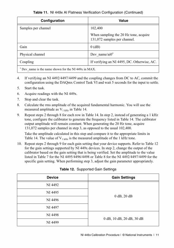
Table 11. NI 449x AI Flatness Verification Configuration
Configuration Value
Minimum value –10.0
Maximum value 10.0
Terminal configuration Pseudodifferential
Acquisition mode Finite number of samples
Rate 204,800.0
NI 449x Calibration Procedure | © National Instruments | 11
4. If verifying an NI 4492/4497/4499 and the coupling changes from DC to AC, commit the configuration using the DAQmx Control Task VI and wait 5 seconds for the input to settle.
5. Start the task.
6. Acquire readings with the NI 449x.
7. Stop and clear the task.
8. Calculate the rms amplitude of the acquired fundamental harmonic. You will use the measured amplitude as V1 kHz in Table 14.
9. Repeat steps 2 through 8 for each row in Table 14. In step 2, instead of generating a 1 kHz tone, configure the calibrator to generate the frequency listed in Table 14. The calibrator output amplitude will remain constant. When generating the 20 Hz tone, acquire 131,072 samples per channel in step 3, as opposed to the usual 102,400.
Take the amplitude calculated in this step and compare it to the appropriate limits in Table 14. The value of V1 kHz is the measured amplitude of the 1 kHz tone.
10. Repeat steps 2 through 9 for each gain setting that your device supports. Refer to Table 12 for the gain settings supported by NI 449x devices. In step 2, change the output of the calibrator based on the gain setting that is being verified. Set the amplitude to the value listed in Table 7 for the NI 4495/4496/4498 or Table 8 for the NI 4492/4497/4499 for the specific gain setting. When performing step 3, adjust the gain parameter appropriately.
Samples per channel 102,400
When sampling the 20 Hz tone, acquire 131,072 samples per channel.
Gain 0 (dB)
Physical channel Dev_name/ai0*
Coupling If verifying an NI 4495, DC. Otherwise, AC.
* Dev_name is the name shown for the NI 449x in MAX.
Table 12. Supported Gain Settings
Device Gain Settings
NI 4492
0 dB, 20 dBNI 4495
NI 4496
NI 4497
NI 44980 dB, 10 dB, 20 dB, 30 dB
NI 4499
Table 11. NI 449x AI Flatness Verification Configuration (Continued)
Configuration Value
12 | ni.com | NI 449x Calibration Procedure
11. Repeat steps 1 through 10 for all input channels on the device. Connect the output of the calibrator to the channel being verified during step 1. In step 3, replace ai0 in the physical channel parameter with the channel being verified.
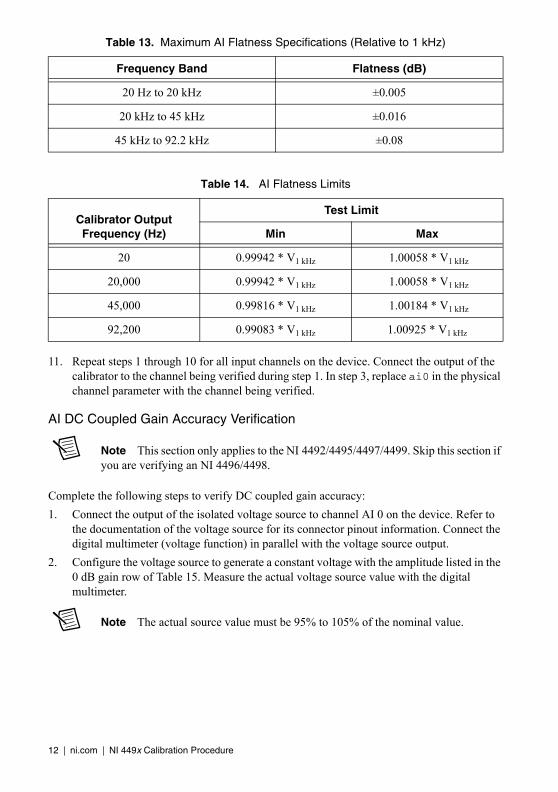
AI DC Coupled Gain Accuracy Verification
Note This section only applies to the NI 4492/4495/4497/4499. Skip this section if you are verifying an NI 4496/4498.
Complete the following steps to verify DC coupled gain accuracy:
1. Connect the output of the isolated voltage source to channel AI 0 on the device. Refer to the documentation of the voltage source for its connector pinout information. Connect the digital multimeter (voltage function) in parallel with the voltage source output.
2. Configure the voltage source to generate a constant voltage with the amplitude listed in the 0 dB gain row of Table 15. Measure the actual voltage source value with the digital multimeter.
Note The actual source value must be 95% to 105% of the nominal value.
Table 13. Maximum AI Flatness Specifications (Relative to 1 kHz)
Frequency Band Flatness (dB)
20 Hz to 20 kHz ±0.005
20 kHz to 45 kHz ±0.016
45 kHz to 92.2 kHz ±0.08
Table 14. AI Flatness Limits
Calibrator Output Frequency (Hz)
Test Limit
Min Max
20 0.99942 * V1 kHz 1.00058 * V1 kHz
20,000 0.99942 * V1 kHz 1.00058 * V1 kHz
45,000 0.99816 * V1 kHz 1.00184 * V1 kHz
92,200 0.99083 * V1 kHz 1.00925 * V1 kHz
NI 449x Calibration Procedure | © National Instruments | 13
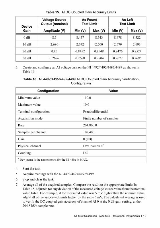
3. Create and configure an AI voltage task on the NI 4492/4495/4497/4499 as shown in Table 16.
4. Start the task.
5. Acquire readings with the NI 4492/4495/4497/4499.
6. Stop and clear the task.
7. Average all of the acquired samples. Compare the result to the appropriate limits in Table 15, adjusted for any deviation of the measured voltage source value from the nominal value listed. For example, if the measured value was 5 mV higher than the nominal value, adjust all of the associated limits higher by the same 5 mV. The calculated average is used to verify the DC coupled gain accuracy of channel AI 0 at the 0 dB gain setting, at the 204.8 kS/s sample rate.
Table 15. AI DC Coupled Gain Accuracy Limits
Device Gain
Voltage Source Output (nominal)
As FoundTest Limit
As LeftTest Limit
Amplitude (V) Min (V) Max (V) Min (V) Max (V)
0 dB 8.5 8.457 8.543 8.478 8.522
10 dB 2.686 2.672 2.700 2.679 2.693
20 dB 0.85 0.8452 0.8548 0.8476 0.8524
30 dB 0.2686 0.2668 0.2704 0.2677 0.2695
Table 16. NI 4492/4495/4497/4499 AI DC Coupled Gain Accuracy Verification Configuration
Configuration Value
Minimum value –10.0
Maximum value 10.0
Terminal configuration Pseudodifferential
Acquisition mode Finite number of samples
Rate 204,800.0
Samples per channel 102,400
Gain 0 (dB)
Physical channel Dev_name/ai0*
Coupling DC
* Dev_name is the name shown for the NI 449x in MAX.
14 | ni.com | NI 449x Calibration Procedure
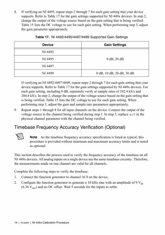
8. If verifying an NI 4495, repeat steps 2 through 7 for each gain setting that your device supports. Refer to Table 17 for the gain settings supported by NI 449x devices. In step 2, change the output of the voltage source based on the gain setting that is being verified. Table 15 lists the DC voltage to use for each gain setting. When performing step 3, adjust the gain parameter appropriately.
If verifying an NI 4492/4497/4499, repeat steps 2 through 7 for each gain setting that your device supports. Refer to Table 17 for the gain settings supported by NI 449x devices. For each gain setting, including 0 dB, separately verify at sample rates of 102.4 kS/s and 204.8 kS/s. In step 2, change the output of the voltage source based on the gain setting that is being verified. Table 15 lists the DC voltage to use for each gain setting. When performing step 3, adjust the gain and sample rate parameters appropriately.
9. Repeat steps 1 through 8 for all input channels on the device. Connect the output of the voltage source to the channel being verified during step 1. In step 3, replace ai0 in the physical channel parameter with the channel being verified.
Timebase Frequency Accuracy Verification (Optional)
Note As the timebase frequency accuracy specification is listed as typical, this procedure is provided without minimum and maximum accuracy limits and is noted as optional.
This section describes the process used to verify the frequency accuracy of the timebase on all NI 449x devices. All analog inputs on a single device use the same timebase circuitry. Therefore, the measurements made on one channel are valid for all channels.
Complete the following steps to verify the timebase:
1. Connect the function generator to channel AI 0 on the device.
2. Configure the function generator to generate a 10 kHz sine with an amplitude of 9 Vpk (6.36 Vrms) and no DC offset. Wait 5 seconds for the inputs to settle.
Table 17. NI 4492/4495/4497/4499 Supported Gain Settings
Device Gain Settings
NI 4492
0 dB, 20 dBNI 4495
NI 4497
NI 4499 0 dB, 10 dB, 20 dB, 30 dB
NI 449x Calibration Procedure | © National Instruments | 15
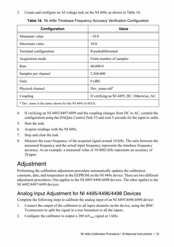
3. Create and configure an AI voltage task on the NI 449x as shown in Table 18.
4. If verifying an NI 4492/4497/4499 and the coupling changes from DC to AC, commit the configuration using the DAQmx Control Task VI and wait 5 seconds for the input to settle.
5. Start the task.
6. Acquire readings with the NI 449x.
7. Stop and clear the task.
8. Measure the exact frequency of the acquired signal around 10 kHz. The ratio between the measured frequency and the actual input frequency represents the timebase frequency accuracy. As an example, a measured value of 10.0002 kHz represents an accuracy of 20 ppm.
AdjustmentPerforming the calibration adjustment procedure automatically updates the calibration constants, date, and temperature in the EEPROM on the NI 449x device. There are two different adjustment procedures. One applies to the NI 4495/4496/4498 devices. The other applies to the NI 4492/4497/4499 devices.
Analog Input Adjustment for NI 4495/4496/4498 DevicesComplete the following steps to calibrate the analog input of an NI 4495/4496/4498 device:
1. Connect the output of the calibrator to all input channels on the device, using the BNC T-connectors to split the signal in a tree formation to all the inputs.
2. Configure the calibrator to output a 200 mVrms signal at 1 kHz.
Table 18. NI 449x Timebase Frequency Accuracy Verification Configuration
Configuration Value
Minimum value –10.0
Maximum value 10.0
Terminal configuration Pseudodifferential
Acquisition mode Finite number of samples
Rate 40,000.0
Samples per channel 2,560,000
Gain 0 (dB)
Physical channel Dev_name/ai0*
Coupling If verifying an NI 4495, DC. Otherwise, AC.
* Dev_name is the name shown for the NI 449x in MAX.
16 | ni.com | NI 449x Calibration Procedure
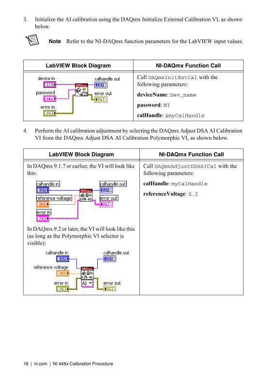
3. Initialize the AI calibration using the DAQmx Initialize External Calibration VI, as shown below.
Note Refer to the NI-DAQmx function parameters for the LabVIEW input values.
4. Perform the AI calibration adjustment by selecting the DAQmx Adjust DSA AI Calibration VI from the DAQmx Adjust DSA AI Calibration Polymorphic VI, as shown below.
LabVIEW Block Diagram NI-DAQmx Function Call
Call DAQmxInitExtCal with the following parameters:
deviceName: Dev_name
password: NI
calHandle: &myCalHandle
LabVIEW Block Diagram NI-DAQmx Function Call
In DAQmx 9.1.7 or earlier, the VI will look like this:
In DAQmx 9.2 or later, the VI will look like this (as long as the Polymorphic VI selector is visible):
Call DAQmxAdjustDSAAICal with the following parameters:
calHandle: myCalHandle
referenceVoltage: 0.2
NI 449x Calibration Procedure | © National Instruments | 17
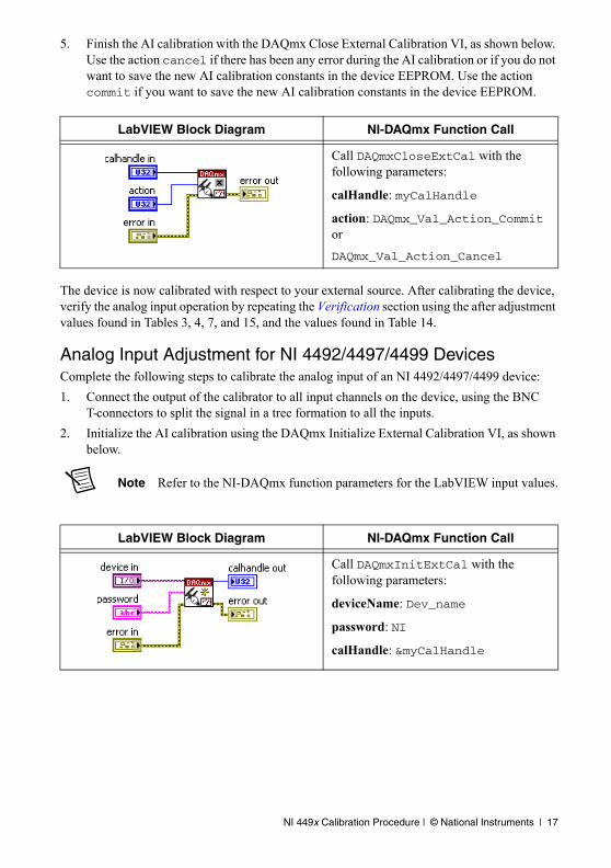
5. Finish the AI calibration with the DAQmx Close External Calibration VI, as shown below. Use the action cancel if there has been any error during the AI calibration or if you do not want to save the new AI calibration constants in the device EEPROM. Use the action commit if you want to save the new AI calibration constants in the device EEPROM.
The device is now calibrated with respect to your external source. After calibrating the device, verify the analog input operation by repeating the Verification section using the after adjustment values found in Tables 3, 4, 7, and 15, and the values found in Table 14.
Analog Input Adjustment for NI 4492/4497/4499 DevicesComplete the following steps to calibrate the analog input of an NI 4492/4497/4499 device:
1. Connect the output of the calibrator to all input channels on the device, using the BNC T-connectors to split the signal in a tree formation to all the inputs.
2. Initialize the AI calibration using the DAQmx Initialize External Calibration VI, as shown below.
Note Refer to the NI-DAQmx function parameters for the LabVIEW input values.
LabVIEW Block Diagram NI-DAQmx Function Call
Call DAQmxCloseExtCal with the following parameters:
calHandle: myCalHandle
action: DAQmx_Val_Action_Commit or
DAQmx_Val_Action_Cancel
LabVIEW Block Diagram NI-DAQmx Function Call
Call DAQmxInitExtCal with the following parameters:
deviceName: Dev_name
password: NI
calHandle: &myCalHandle
18 | ni.com | NI 449x Calibration Procedure
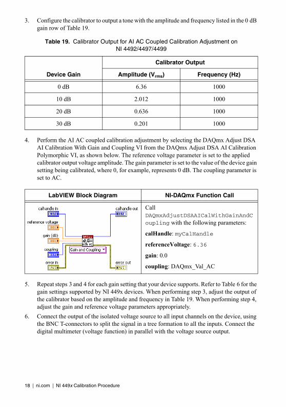
3. Configure the calibrator to output a tone with the amplitude and frequency listed in the 0 dB gain row of Table 19.
4. Perform the AI AC coupled calibration adjustment by selecting the DAQmx Adjust DSA AI Calibration With Gain and Coupling VI from the DAQmx Adjust DSA AI Calibration Polymorphic VI, as shown below. The reference voltage parameter is set to the applied calibrator output voltage amplitude. The gain parameter is set to the value of the device gain setting being calibrated, where 0, for example, represents 0 dB. The coupling parameter is set to AC.
5. Repeat steps 3 and 4 for each gain setting that your device supports. Refer to Table 6 for the gain settings supported by NI 449x devices. When performing step 3, adjust the output of the calibrator based on the amplitude and frequency in Table 19. When performing step 4, adjust the gain and reference voltage parameters appropriately.
6. Connect the output of the isolated voltage source to all input channels on the device, using the BNC T-connectors to split the signal in a tree formation to all the inputs. Connect the digital multimeter (voltage function) in parallel with the voltage source output.
Table 19. Calibrator Output for AI AC Coupled Calibration Adjustment on NI 4492/4497/4499
Device Gain
Calibrator Output
Amplitude (Vrms) Frequency (Hz)
0 dB 6.36 1000
10 dB 2.012 1000
20 dB 0.636 1000
30 dB 0.201 1000
LabVIEW Block Diagram NI-DAQmx Function Call
Call DAQmxAdjustDSAAICalWithGainAndCoupling with the following parameters:
calHandle: myCalHandle
referenceVoltage: 6.36
gain: 0.0
coupling: DAQmx_Val_AC
NI 449x Calibration Procedure | © National Instruments | 19
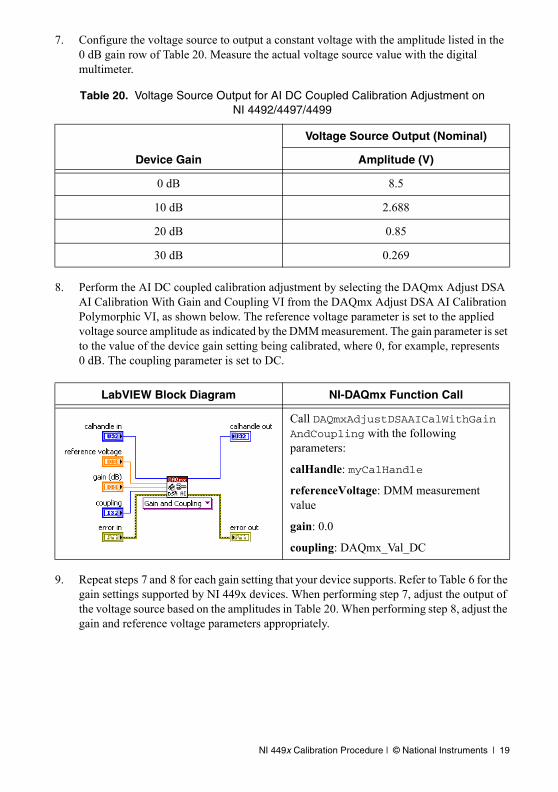
7. Configure the voltage source to output a constant voltage with the amplitude listed in the 0 dB gain row of Table 20. Measure the actual voltage source value with the digital multimeter.
8. Perform the AI DC coupled calibration adjustment by selecting the DAQmx Adjust DSA AI Calibration With Gain and Coupling VI from the DAQmx Adjust DSA AI Calibration Polymorphic VI, as shown below. The reference voltage parameter is set to the applied voltage source amplitude as indicated by the DMM measurement. The gain parameter is set to the value of the device gain setting being calibrated, where 0, for example, represents 0 dB. The coupling parameter is set to DC.
9. Repeat steps 7 and 8 for each gain setting that your device supports. Refer to Table 6 for the gain settings supported by NI 449x devices. When performing step 7, adjust the output of the voltage source based on the amplitudes in Table 20. When performing step 8, adjust the gain and reference voltage parameters appropriately.
Table 20. Voltage Source Output for AI DC Coupled Calibration Adjustment on NI 4492/4497/4499
Device Gain
Voltage Source Output (Nominal)
Amplitude (V)
0 dB 8.5
10 dB 2.688
20 dB 0.85
30 dB 0.269
LabVIEW Block Diagram NI-DAQmx Function Call
Call DAQmxAdjustDSAAICalWithGainAndCoupling with the following parameters:
calHandle: myCalHandle
referenceVoltage: DMM measurement value
gain: 0.0
coupling: DAQmx_Val_DC
20 | ni.com | NI 449x Calibration Procedure
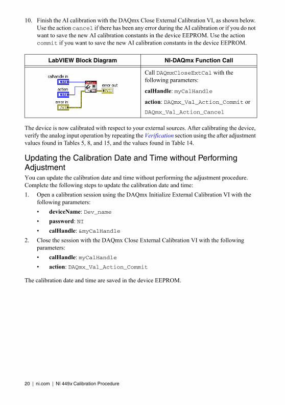
10. Finish the AI calibration with the DAQmx Close External Calibration VI, as shown below. Use the action cancel if there has been any error during the AI calibration or if you do not want to save the new AI calibration constants in the device EEPROM. Use the action commit if you want to save the new AI calibration constants in the device EEPROM.
The device is now calibrated with respect to your external sources. After calibrating the device, verify the analog input operation by repeating the Verification section using the after adjustment values found in Tables 5, 8, and 15, and the values found in Table 14.
Updating the Calibration Date and Time without Performing AdjustmentYou can update the calibration date and time without performing the adjustment procedure. Complete the following steps to update the calibration date and time:
1. Open a calibration session using the DAQmx Initialize External Calibration VI with the following parameters:
• deviceName: Dev_name
• password: NI
• calHandle: &myCalHandle
2. Close the session with the DAQmx Close External Calibration VI with the following parameters:
• calHandle: myCalHandle
• action: DAQmx_Val_Action_Commit
The calibration date and time are saved in the device EEPROM.
LabVIEW Block Diagram NI-DAQmx Function Call
Call DAQmxCloseExtCal with the following parameters:
calHandle: myCalHandle
action: DAQmx_Val_Action_Commit or
DAQmx_Val_Action_Cancel
© 2008–2012 National Instruments. All rights reserved.
372577E-01 Jul12
LabVIEW, National Instruments, NI, ni.com, the National Instruments corporate logo, and the Eagle logo are trademarks of National Instruments Corporation. Refer to the Trademark Information at ni.com/trademarks for other National Instruments trademarks. Other product and company names mentioned herein are trademarks or trade names of their respective companies. For patents covering National Instruments products/technology, refer to the appropriate location: Help»Patents in your software, the patents.txt file on your media, or the National Instruments Patents Notice at ni.com/patents. Refer to the Export Compliance Information at ni.com/legal/export-compliance for the National Instruments global trade compliance policy and how to obtain relevant HTS codes, ECCNs, and other import/export data.
Where to Go for SupportThe National Instruments Web site is your complete resource for technical support. At ni.com/support you have access to everything from troubleshooting and application development self-help resources to email and phone assistance from NI Application Engineers.
A Declaration of Conformity (DoC) is our claim of compliance with the Council of the European Communities using the manufacturer’s declaration of conformity. This system affords the user protection for electromagnetic compatibility (EMC) and product safety. You can obtain the DoC for your product by visiting ni.com/certification. If your product supports calibration, you can obtain the calibration certificate for your product at ni.com/calibration.
National Instruments corporate headquarters is located at 11500 North Mopac Expressway, Austin, Texas, 78759-3504. National Instruments also has offices located around the world to help address your support needs. For telephone support in the United States, create your service request at ni.com/support and follow the calling instructions or dial 512 795 8248. For telephone support outside the United States, visit the Worldwide Offices section of ni.com/niglobal to access the branch office Web sites, which provide up-to-date contact information, support phone numbers, email addresses, and current events.