NF Circuit Breaker Panelboards - Steven...
32
Schneider Electric Brands NF Circuit Breaker Panelboards Class 1670 CONTENTS Description Page NF Standard Width Panelboards Application Data . . . . . . . . . . . . . . . . . . . . . . . . . . . . . . . . . . . . . . . . . . . . . . . . . . . . 2 Typical Wiring Diagrams . . . . . . . . . . . . . . . . . . . . . . . . . . . . . . . . . . . . . . . . . . . . . 13 Dimensions . . . . . . . . . . . . . . . . . . . . . . . . . . . . . . . . . . . . . . . . . . . . . . . . . . . . . . . 14 Replacement Parts . . . . . . . . . . . . . . . . . . . . . . . . . . . . . . . . . . . . . . . . . . . . . . . . . 21 NF Column Width Panelboards Application Data . . . . . . . . . . . . . . . . . . . . . . . . . . . . . . . . . . . . . . . . . . . . . . . . . . . 28 Typical Wiring Diagrams and Dimensions. . . . . . . . . . . . . . . . . . . . . . . . . . . . . . . . 30 Replacement Parts . . . . . . . . . . . . . . . . . . . . . . . . . . . . . . . . . . . . . . . . . . . . . . . . . 31
-
Upload
nguyendien -
Category
Documents
-
view
225 -
download
4
Transcript of NF Circuit Breaker Panelboards - Steven...
Schneider Electric Brands
NF Circuit Breaker Panelboards
Class 1670
CONTENTS
Description PageNF Standard Width Panelboards
Application Data . . . . . . . . . . . . . . . . . . . . . . . . . . . . . . . . . . . . . . . . . . . . . . . . . . . . 2Typical Wiring Diagrams . . . . . . . . . . . . . . . . . . . . . . . . . . . . . . . . . . . . . . . . . . . . . 13Dimensions . . . . . . . . . . . . . . . . . . . . . . . . . . . . . . . . . . . . . . . . . . . . . . . . . . . . . . . 14Replacement Parts . . . . . . . . . . . . . . . . . . . . . . . . . . . . . . . . . . . . . . . . . . . . . . . . . 21
NF Column Width PanelboardsApplication Data . . . . . . . . . . . . . . . . . . . . . . . . . . . . . . . . . . . . . . . . . . . . . . . . . . . 28Typical Wiring Diagrams and Dimensions. . . . . . . . . . . . . . . . . . . . . . . . . . . . . . . . 30Replacement Parts . . . . . . . . . . . . . . . . . . . . . . . . . . . . . . . . . . . . . . . . . . . . . . . . . 31
NF Standard Width PanelboardsApplication Data
©2
Service
Voltage System System Diagram
120/240 Vac 1φ3W
208Y/120 Vac 3φ4W
240/120 Vac3φ4WDelta
240 Vac3φ3WDelta
240 Vac3φ3W
Grounded BφDelta
480Y/277 Vac 3φ4W
250 A Main Lugs 250 A MainCircuit Breaker
EDB Branch Circuit Breakers
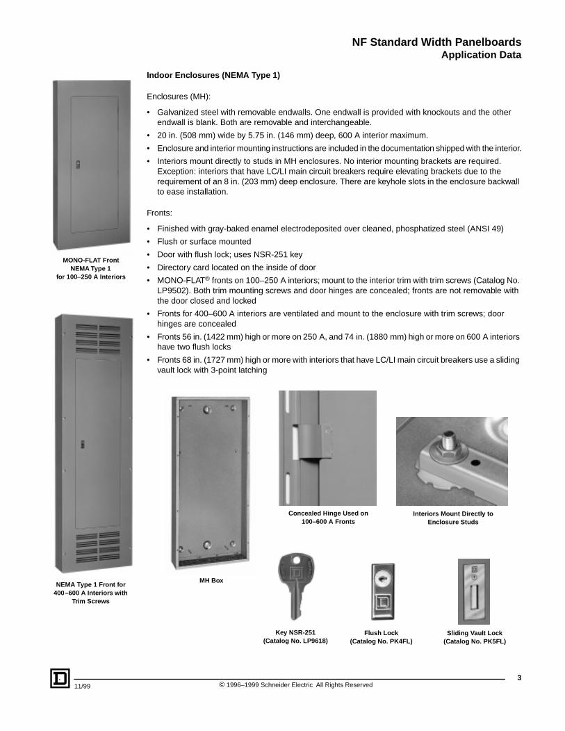
Type
NF circuit breaker panelboards are for use on ac systems. They are UL® Listed under File E33139 and CSA certified under File LL1809. NF circuit breaker panelboards accept EDB, EGB, and EJB branch circuit breakers.
Standards
NF circuit breaker panelboards are designed, manufactured, and tested to comply with the following standards:
• UL 67—Standard for Panelboards
• UL 50—Enclosures for Electrical Equipment
• UL Listed Class CTL panelboard; meets paragraph 384-15 of the NEC
• CSA C22.2, No. 29-1989—Panelboards and Enclosed Panelboards
• NEMA PB 1—Panelboards
• NFPA 70—National Electrical Code® (NEC®)
• Federal Specification W-P-115C Type I Class 1—Circuit Breaker Panelboards
Ratings
• Main lugs: 125–600 A
• Main circuit breaker: 100–600 A
Branch Circuit Breakers (Bolt-on), 480Y/277 Vac
18,000 AIR, EDB 35,000 AIR, EGB 65,000 AIR, EJB1-pole, 15–70 A 1-pole, 15–70 A 1-pole, 15–70 A2-pole, 15–125 A 2-pole, 15–125 A 2-pole, 15–125 A3-pole, 15–125 A 3-pole, 15–125 A 3-pole, 15–125 A
NF Panelboard 480Y/277 Vac Short Circuit Current Ratings (SCCR)
SCCRFully Rated
or Series Rated
Integral Mains (Main Circuit Breaker Maximum Amperage)
Remote Mains (Maximum Amperage)
Branch Circuit
Breakers
18,000 A Fully Rated EDB (125 A) FA (100 A), EDB (125 A) EDB
25,000 A Fully Rated KA (250 A) FH (100 A), KA (250 A) EGB
30,000 A Fully Rated LA (400 A) LA (400 A) EGB
35,000 A
Fully RatedEGB (125 A), KH (250 A), LH (400 A)
EGB (125 A), KH (250 A), LH (400 A) EGB
Series RatedEGB (125 A), KH (250 A), LH (400 A)
EGB (125 A), KH (250 A), LH (400 A) EDB
65,000 A
Fully RatedEJB (125 A), FC (100 A), KC (250 A), LC (600 A)
FC (100 A), EJB (125 A), KC (250 A), LC (600 A), LX (600 A)
EJB
Series RatedEJB (125 A), FC (100 A), KC (250 A), LC (600 A)
FC (100 A), EJB (125 A), KC (250 A), LC (600 A), LX (600 A)
EDB, EGB
100,000 A Series Rated Class J/T fuse (400 A max., 600 V) EDB, EGB, EJB
200,000 A Series RatedFI (100 A), KI (250 A), LI (600 A)
FI (100 A), KI (250 A), LI (600 A), LXI (600 A), Class J/T fuse (200 A max., 600 V)
EDB, EGB, EJB
1996–1999 Schneider Electric All Rights Reserved 11/99
NF Standard Width PanelboardsApplication Data
11/99
NEMA Type 1 Front for 400–600 A Interiors with
Trim Screws
MONO-FLAT Front NEMA Type 1
for 100 –250 A Interiors
Indoor Enclosures (NEMA Type 1)
Enclosures (MH):
• Galvanized steel with removable endwalls. One endwall is provided with knockouts and the other endwall is blank. Both are removable and interchangeable.
• 20 in. (508 mm) wide by 5.75 in. (146 mm) deep, 600 A interior maximum.
• Enclosure and interior mounting instructions are included in the documentation shipped with the interior.
• Interiors mount directly to studs in MH enclosures. No interior mounting brackets are required. Exception: interiors that have LC/LI main circuit breakers require elevating brackets due to the requirement of an 8 in. (203 mm) deep enclosure. There are keyhole slots in the enclosure backwall to ease installation.
Fronts:
• Finished with gray-baked enamel electrodeposited over cleaned, phosphatized steel (ANSI 49)
• Flush or surface mounted
• Door with flush lock; uses NSR-251 key
• Directory card located on the inside of door
• MONO-FLAT® fronts on 100–250 A interiors; mount to the interior trim with trim screws (Catalog No. LP9502). Both trim mounting screws and door hinges are concealed; fronts are not removable with the door closed and locked
• Fronts for 400–600 A interiors are ventilated and mount to the enclosure with trim screws; door hinges are concealed
• Fronts 56 in. (1422 mm) high or more on 250 A, and 74 in. (1880 mm) high or more on 600 A interiors have two flush locks
• Fronts 68 in. (1727 mm) high or more with interiors that have LC/LI main circuit breakers use a sliding vault lock with 3-point latching
Concealed Hinge Used on100–600 A Fronts
Interiors Mount Directly to Enclosure Studs
Key NSR-251(Catalog No. LP9618)
Flush Lock (Catalog No. PK4FL)
Sliding Vault Lock(Catalog No. PK5FL)
MH Box
3© 1996–1999 Schneider Electric All Rights Reserved
NF Standard Width PanelboardsApplication Data
©4
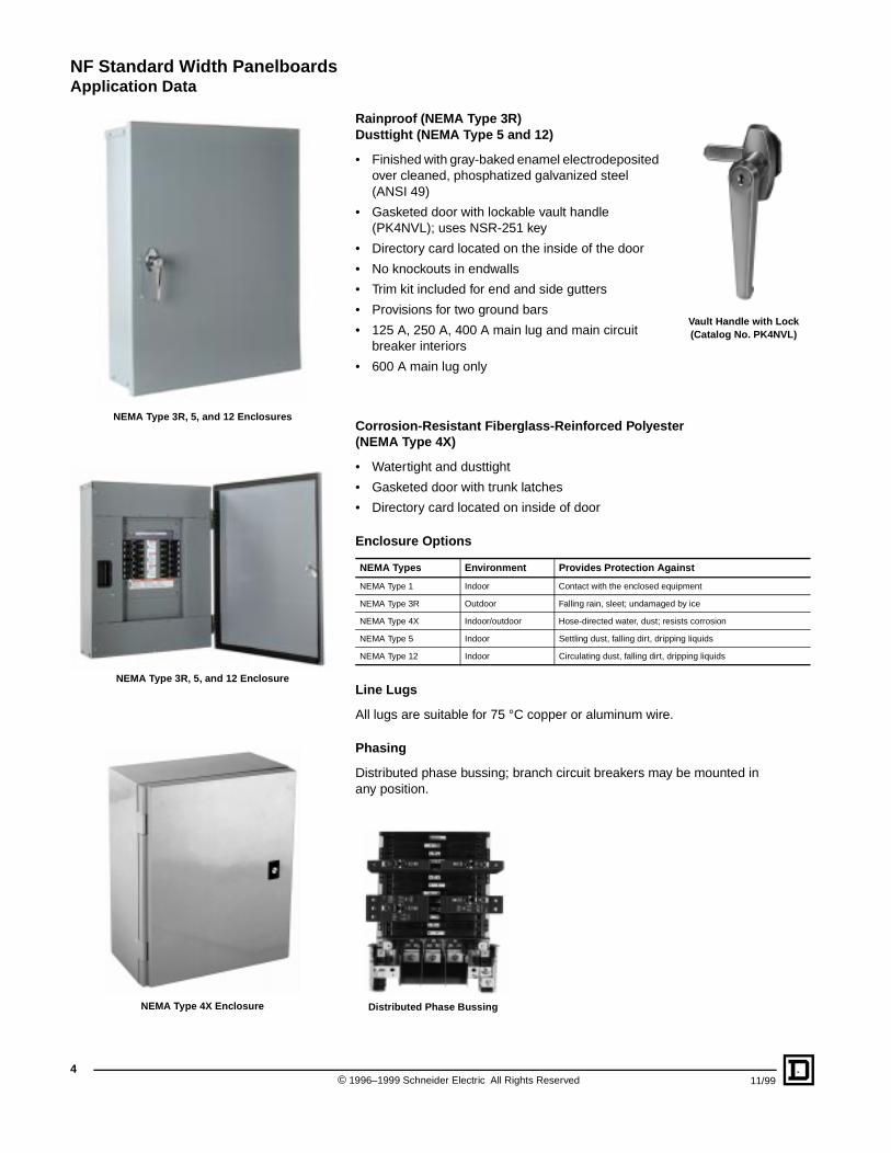
NEMA Type 3R, 5, and 12 Enclosure
NEMA Type 3R, 5, and 12 Enclosures
NEMA Type 4X Enclosure
Rainproof (NEMA Type 3R)Dusttight (NEMA Type 5 and 12)
• Finished with gray-baked enamel electrodeposited over cleaned, phosphatized galvanized steel (ANSI 49)
• Gasketed door with lockable vault handle (PK4NVL); uses NSR-251 key
• Directory card located on the inside of the door
• No knockouts in endwalls
• Trim kit included for end and side gutters
• Provisions for two ground bars
• 125 A, 250 A, 400 A main lug and main circuit breaker interiors
• 600 A main lug only
1996–1999 Schneider Electric All Rights Reserved
Vault Handle with Lock (Catalog No. PK4NVL)
Corrosion-Resistant Fiberglass-Reinforced Polyester(NEMA Type 4X)
• Watertight and dusttight
• Gasketed door with trunk latches
• Directory card located on inside of door
Enclosure Options
Line Lugs
All lugs are suitable for 75 °C copper or aluminum wire.
Phasing
Distributed phase bussing; branch circuit breakers may be mounted in any position.
NEMA Types Environment Provides Protection Against
NEMA Type 1 Indoor Contact with the enclosed equipment
NEMA Type 3R Outdoor Falling rain, sleet; undamaged by ice
NEMA Type 4X Indoor/outdoor Hose-directed water, dust; resists corrosion
NEMA Type 5 Indoor Settling dust, falling dirt, dripping liquids
NEMA Type 12 Indoor Circulating dust, falling dirt, dripping liquids
Distributed Phase Bussing
11/99
NF Standard Width PanelboardsApplication Data
11/99 ©
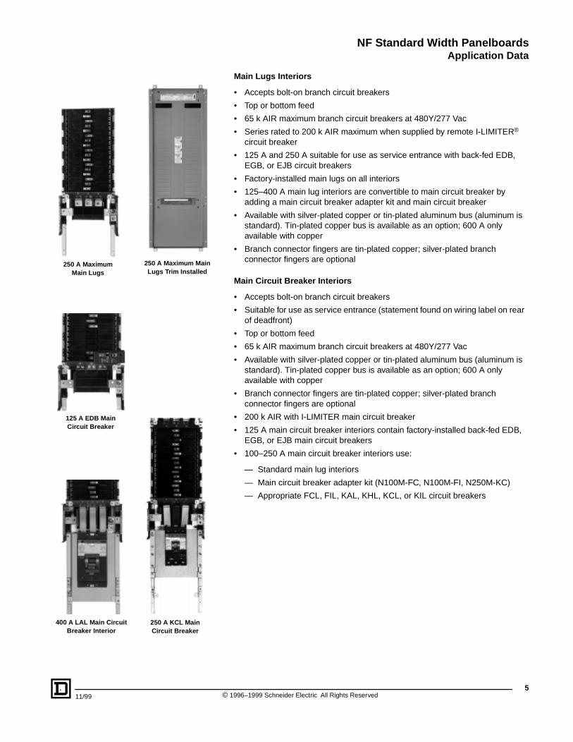
250 A Maximum Main Lugs
250 A Maximum Main Lugs Trim Installed
125 A EDB Main Circuit Breaker
250 A KCL Main Circuit Breaker
400 A LAL Main Circuit Breaker Interior
Main Lugs Interiors
• Accepts bolt-on branch circuit breakers
• Top or bottom feed
• 65 k AIR maximum branch circuit breakers at 480Y/277 Vac
• Series rated to 200 k AIR maximum when supplied by remote I-LIMITER® circuit breaker
• 125 A and 250 A suitable for use as service entrance with back-fed EDB, EGB, or EJB circuit breakers
• Factory-installed main lugs on all interiors
• 125–400 A main lug interiors are convertible to main circuit breaker by adding a main circuit breaker adapter kit and main circuit breaker
• Available with silver-plated copper or tin-plated aluminum bus (aluminum is standard). Tin-plated copper bus is available as an option; 600 A only available with copper
• Branch connector fingers are tin-plated copper; silver-plated branch connector fingers are optional
Main Circuit Breaker Interiors
• Accepts bolt-on branch circuit breakers
• Suitable for use as service entrance (statement found on wiring label on rear of deadfront)
• Top or bottom feed
• 65 k AIR maximum branch circuit breakers at 480Y/277 Vac
• Available with silver-plated copper or tin-plated aluminum bus (aluminum is standard). Tin-plated copper bus is available as an option; 600 A only available with copper
• Branch connector fingers are tin-plated copper; silver-plated branch connector fingers are optional
• 200 k AIR with I-LIMITER main circuit breaker
• 125 A main circuit breaker interiors contain factory-installed back-fed EDB, EGB, or EJB main circuit breakers
• 100–250 A main circuit breaker interiors use:
— Standard main lug interiors
— Main circuit breaker adapter kit (N100M-FC, N100M-FI, N250M-KC)
— Appropriate FCL, FIL, KAL, KHL, KCL, or KIL circuit breakers
5 1996–1999 Schneider Electric All Rights Reserved
NF Standard Width PanelboardsApplication Data
©6
Main Circuit Breaker Interiors, continued
• 400 A main circuit breaker interiors use:
— Standard main lug interior
— Main circuit breaker adapter kit (N400M)
— Appropriate LAL or LHL circuit breaker
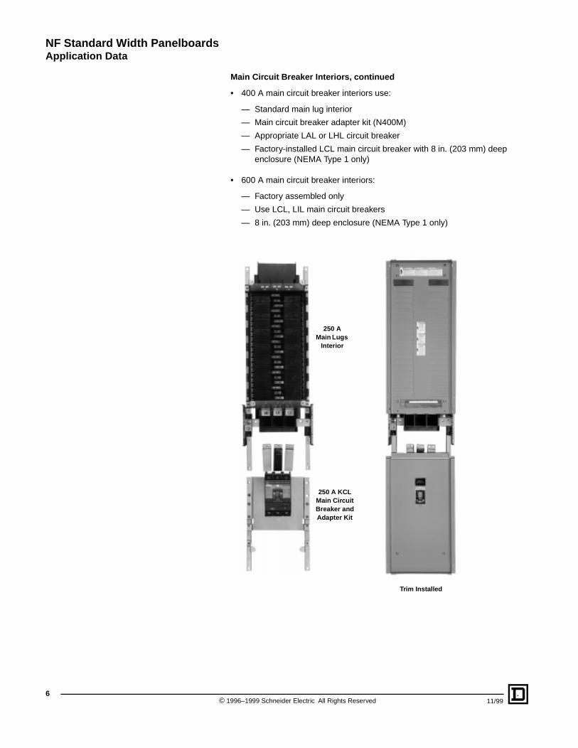
— Factory-installed LCL main circuit breaker with 8 in. (203 mm) deep enclosure (NEMA Type 1 only)
• 600 A main circuit breaker interiors:
— Factory assembled only
— Use LCL, LIL main circuit breakers
— 8 in. (203 mm) deep enclosure (NEMA Type 1 only)
250 A Main Lugs
Interior
250 A KCL Main Circuit Breaker and Adapter Kit
Trim Installed
1996–1999 Schneider Electric All Rights Reserved 11/99
NF Standard Width PanelboardsApplication Data
11/99 ©
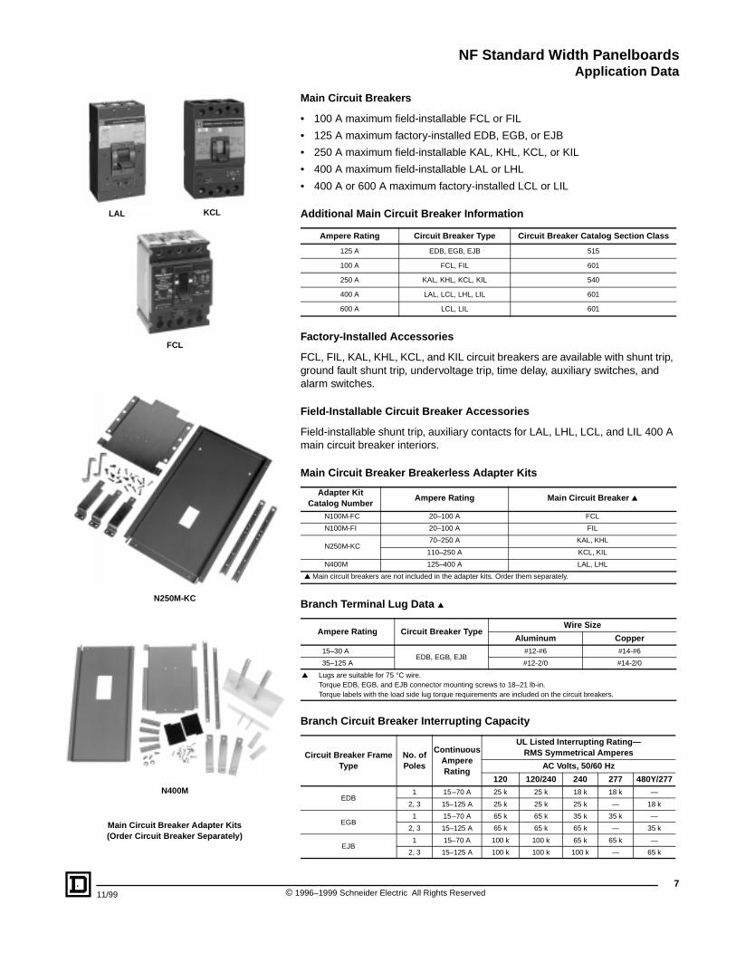
LAL KCL
FCL
Main Circuit Breaker Adapter Kits (Order Circuit Breaker Separately)
N400M
N250M-KC
Main Circuit Breakers
• 100 A maximum field-installable FCL or FIL
• 125 A maximum factory-installed EDB, EGB, or EJB
• 250 A maximum field-installable KAL, KHL, KCL, or KIL
• 400 A maximum field-installable LAL or LHL
• 400 A or 600 A maximum factory-installed LCL or LIL
Additional Main Circuit Breaker Information
Factory-Installed Accessories
FCL, FIL, KAL, KHL, KCL, and KIL circuit breakers are available with shunt trip, ground fault shunt trip, undervoltage trip, time delay, auxiliary switches, and alarm switches.
Field-Installable Circuit Breaker Accessories
Field-installable shunt trip, auxiliary contacts for LAL, LHL, LCL, and LIL 400 A main circuit breaker interiors.
Main Circuit Breaker Breakerless Adapter Kits
Branch Terminal Lug Data ▲
Branch Circuit Breaker Interrupting Capacity
Ampere Rating Circuit Breaker Type Circuit Breaker Catalog Section Class
125 A EDB, EGB, EJB 515
100 A FCL, FIL 601
250 A KAL, KHL, KCL, KIL 540
400 A LAL, LCL, LHL, LIL 601
600 A LCL, LIL 601
Adapter Kit Catalog Number
Ampere Rating Main Circuit Breaker ▲
N100M-FC 20–100 A FCL
N100M-FI 20–100 A FIL
N250M-KC70–250 A KAL, KHL
110–250 A KCL, KIL
N400M 125–400 A LAL, LHL
▲ Main circuit breakers are not included in the adapter kits. Order them separately.
Ampere Rating Circuit Breaker TypeWire Size
Aluminum Copper15–30 A
EDB, EGB, EJB#12-#6 #14-#6
35–125 A #12-2/0 #14-2/0
▲ Lugs are suitable for 75 °C wire.Torque EDB, EGB, and EJB connector mounting screws to 18–21 lb-in.Torque labels with the load side lug torque requirements are included on the circuit breakers.
Circuit Breaker Frame Type
No. of Poles
Continuous Ampere Rating
UL Listed Interrupting Rating—RMS Symmetrical Amperes
AC Volts, 50/60 Hz
120 120/240 240 277 480Y/277
EDB1 15–70 A 25 k 25 k 18 k 18 k —
2, 3 15–125 A 25 k 25 k 25 k — 18 k
EGB1 15–70 A 65 k 65 k 35 k 35 k —
2, 3 15–125 A 65 k 65 k 65 k — 35 k
EJB1 15–70 A 100 k 100 k 65 k 65 k —
2, 3 15–125 A 100 k 100 k 100 k — 65 k
7 1996–1999 Schneider Electric All Rights Reserved
NF Standard Width PanelboardsApplication Data
©8
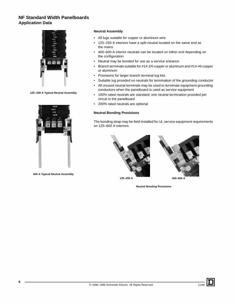
600 A Typical Neutral Assembly
125–250 A Typical Neutral Assembly
Neutral Assembly
• All lugs suitable for copper or aluminum wire• 125–250 A interiors have a split neutral located on the same end as
the mains• 400–600 A interior neutrals can be located on either end depending on
the configuration• Neutral may be bonded for use as a service entrance
• Branch terminals suitable for #14-2/0 copper or aluminum and #14-#6 copper or aluminum
• Provisions for larger branch terminal lug kits• Suitable lug provided on neutrals for termination of the grounding conductor• All unused neutral terminals may be used to terminate equipment grounding
conductors when the panelboard is used as service equipment• 100% rated neutrals are standard; one neutral termination provided per
circuit in the panelboard• 200% rated neutrals are optional
Neutral Bonding Provisions
The bonding strap may be field installed for UL service equipment requirements on 125–600 A interiors.
Neutral Bonding Provisions
125–250 A 400–600 A
1996–1999 Schneider Electric All Rights Reserved 11/99
NF Standard Width PanelboardsApplication Data
11/99 ©
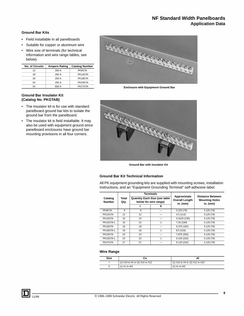
Ground Bar Kits
• Field installable in all panelboards
• Suitable for copper or aluminum wire
• Wire size of terminals (for technical information and wire range tables, see below).
Ground Bar Insulator Kit (Catalog No. PKGTAB)
• The insulator kit is for use with standard panelboard ground bar kits to isolate the ground bar from the panelboard.
• The insulator kit is field installable. It may also be used with equipment ground since panelboard enclosures have ground bar mounting provisions in all four corners.
No. of Circuits Ampere Rating Catalog Number12 250 A PK9GTA
18 250 A PK12GTA
30 250 A PK18GTA
54 250 A PK23GTA
54 600 A PK27GTA
Ground Bar Kit Technical Information
All PK equipment grounding kits are supplied with mounting screws, installation instructions, and an “Equipment Grounding Terminal” self-adhesive label.
Wire Range
Catalog Number
Total Qty.
TerminalsApproximate
Overall Lengthin. (mm)
Distance Between Mounting Holes
in. (mm)
Quantity Each Size (see table below for wire range)
I IIPK9GTA 9 9 — 3.125 (79) 3.125 (79)
PK12GTA 12 12 — 4.5 (114) 3.125 (79)
PK15GTA 15 15 — 5.3125 (135) 3.125 (79)
PK15GTA-L 16 15 1 7.25 (184) 3.125 (79)
PK18GTA 18 18 — 6.375 (162) 3.125 (79)
PK18GTA-L 19 18 1 8.5 (216) 3.125 (79)
PK23GTA 23 23 — 7.875 (200) 3.125 (79)
PK23GTA-L 24 23 1 9.125 (232) 3.125 (79)
PK27GTA 27 27 — 9.125 (232) 3.125 (79)
Size Cu AlI (1) #14 to #4 or (2) #14 or #12 (1) #12 to #4 or (2) #12 or #10
II (1) #1 to 4/0 (1) #1 to 4/0
Enclosure with Equipment Ground Bar
Ground Bar with Insulator Kit
9 1996–1999 Schneider Electric All Rights Reserved
NF Standard Width PanelboardsApplication Data
10
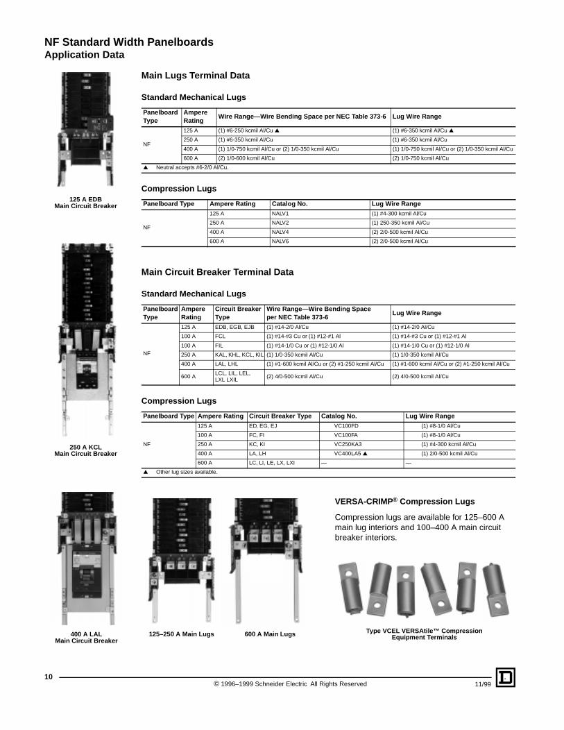
125 A EDBMain Circuit Breaker
250 A KCLMain Circuit Breaker
400 A LALMain Circuit Breaker
Main Lugs Terminal Data
Standard Mechanical Lugs
Compression Lugs
Main Circuit Breaker Terminal Data
Standard Mechanical Lugs
Compression Lugs
Panelboard Type
Ampere Rating
Wire Range—Wire Bending Space per NEC Table 373-6 Lug Wire Range
NF
125 A (1) #6-250 kcmil Al/Cu ▲ (1) #6-350 kcmil Al/Cu ▲
250 A (1) #6-350 kcmil Al/Cu (1) #6-350 kcmil Al/Cu
400 A (1) 1/0-750 kcmil Al/Cu or (2) 1/0-350 kcmil Al/Cu (1) 1/0-750 kcmil Al/Cu or (2) 1/0-350 kcmil Al/Cu
600 A (2) 1/0-600 kcmil Al/Cu (2) 1/0-750 kcmil Al/Cu
▲ Neutral accepts #6-2/0 Al/Cu.
Panelboard Type Ampere Rating Catalog No. Lug Wire Range
NF
125 A NALV1 (1) #4-300 kcmil Al/Cu
250 A NALV2 (1) 250-350 kcmil Al/Cu
400 A NALV4 (2) 2/0-500 kcmil Al/Cu
600 A NALV6 (2) 2/0-500 kcmil Al/Cu
Panelboard Type
Ampere Rating
Circuit Breaker Type
Wire Range—Wire Bending Space per NEC Table 373-6
Lug Wire Range
NF
125 A EDB, EGB, EJB (1) #14-2/0 Al/Cu (1) #14-2/0 Al/Cu
100 A FCL (1) #14-#3 Cu or (1) #12-#1 Al (1) #14-#3 Cu or (1) #12-#1 Al
100 A FIL (1) #14-1/0 Cu or (1) #12-1/0 Al (1) #14-1/0 Cu or (1) #12-1/0 Al
250 A KAL, KHL, KCL, KIL (1) 1/0-350 kcmil Al/Cu (1) 1/0-350 kcmil Al/Cu
400 A LAL, LHL (1) #1-600 kcmil Al/Cu or (2) #1-250 kcmil Al/Cu (1) #1-600 kcmil Al/Cu or (2) #1-250 kcmil Al/Cu
600 ALCL, LIL, LEL, LXL LXIL
(2) 4/0-500 kcmil Al/Cu (2) 4/0-500 kcmil Al/Cu
Panelboard Type Ampere Rating Circuit Breaker Type Catalog No. Lug Wire Range
NF
125 A ED, EG, EJ VC100FD (1) #8-1/0 Al/Cu
100 A FC, FI VC100FA (1) #8-1/0 Al/Cu
250 A KC, KI VC250KA3 (1) #4-300 kcmil Al/Cu
400 A LA, LH VC400LA5 ▲ (1) 2/0-500 kcmil Al/Cu
600 A LC, LI, LE, LX, LXI — —
▲ Other lug sizes available.
VERSA-CRIMP® Compression Lugs
Compression lugs are available for 125–600 A main lug interiors and 100–400 A main circuit breaker interiors.
125–250 A Main Lugs 600 A Main Lugs Type VCEL VERSAtile™ Compression Equipment Terminals
© 1996–1999 Schneider Electric All Rights Reserved 11/99
NF Standard Width PanelboardsApplication Data
11/99 ©
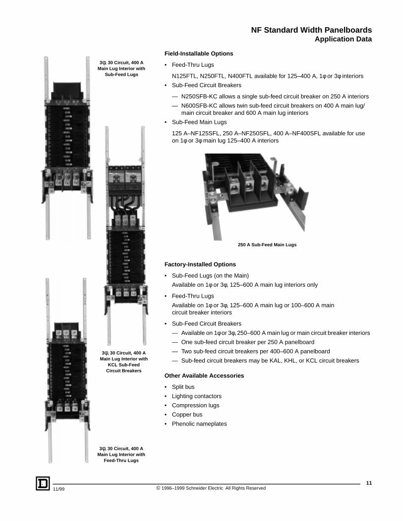
3φ, 30 Circuit, 400 A Main Lug Interior with
Sub-Feed Lugs
3φ, 30 Circuit, 400 A Main Lug Interior with
Feed-Thru Lugs
3φ, 30 Circuit, 400 A Main Lug Interior with
KCL Sub-Feed Circuit Breakers
Field-Installable Options
• Feed-Thru Lugs
N125FTL, N250FTL, N400FTL available for 125–400 A, 1φ or 3φ interiors
• Sub-Feed Circuit Breakers
— N250SFB-KC allows a single sub-feed circuit breaker on 250 A interiors
— N600SFB-KC allows twin sub-feed circuit breakers on 400 A main lug/main circuit breaker and 600 A main lug interiors
• Sub-Feed Main Lugs
125 A–NF125SFL, 250 A–NF250SFL, 400 A–NF400SFL available for use on 1φ or 3φ main lug 125–400 A interiors
Factory-Installed Options
• Sub-Feed Lugs (on the Main)
Available on 1φ or 3φ, 125–600 A main lug interiors only
• Feed-Thru Lugs
Available on 1φ or 3φ, 125–600 A main lug or 100–600 A main circuit breaker interiors
• Sub-Feed Circuit Breakers
— Available on 1φ or 3φ, 250–600 A main lug or main circuit breaker interiors
— One sub-feed circuit breaker per 250 A panelboard
— Two sub-feed circuit breakers per 400–600 A panelboard
— Sub-feed circuit breakers may be KAL, KHL, or KCL circuit breakers
Other Available Accessories
• Split bus
• Lighting contactors
• Compression lugs
• Copper bus
• Phenolic nameplates
250 A Sub-Feed Main Lugs
11 1996–1999 Schneider Electric All Rights Reserved
NF Standard Width PanelboardsApplication Data
©12
Design Features
• Individually fused suppression modes• Thermal cutout
• Inline, copper bus bar connection• Solid state bi-directional• Audible alarm with test/silence switch
• LED indicators indicate loss of protection, or fully operational circuit
• High-energy parallel design for category A, B, and C3 applications
• Available in main circuit breaker and main lug only panelboards with sub-feed circuit breakers, feed-thru lugs, or sub-feed lugs.
• AC tracking filter with EMI/RFI filtering up to -50 dB from 100 kHz to 100 MHz
Performance Features
Surge Capacity
L–N L–G N–G
160 kA / phase 80 k 80 k 120 k
240 kA / phase 120 k 120 k 120 k
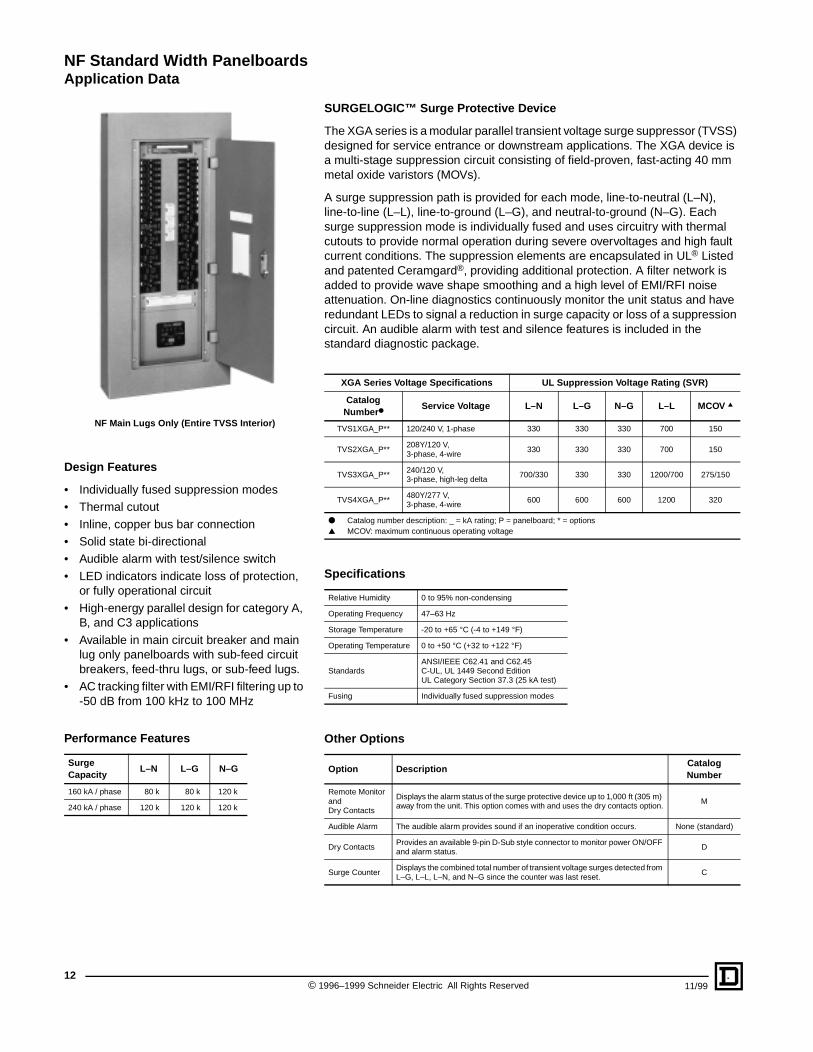
NF Main Lugs Only (Entire TVSS Interior)
SURGELOGIC™ Surge Protective Device
The XGA series is a modular parallel transient voltage surge suppressor (TVSS) designed for service entrance or downstream applications. The XGA device is a multi-stage suppression circuit consisting of field-proven, fast-acting 40 mm metal oxide varistors (MOVs).
A surge suppression path is provided for each mode, line-to-neutral (L–N), line-to-line (L–L), line-to-ground (L–G), and neutral-to-ground (N–G). Each surge suppression mode is individually fused and uses circuitry with thermal cutouts to provide normal operation during severe overvoltages and high fault current conditions. The suppression elements are encapsulated in UL® Listed and patented Ceramgard®, providing additional protection. A filter network is added to provide wave shape smoothing and a high level of EMI/RFI noise attenuation. On-line diagnostics continuously monitor the unit status and have redundant LEDs to signal a reduction in surge capacity or loss of a suppression circuit. An audible alarm with test and silence features is included in the standard diagnostic package.
XGA Series Voltage Specifications UL Suppression Voltage Rating (SVR)
Catalog Number●
Service Voltage L–N L–G N–G L–L MCOV ▲
TVS1XGA_P** 120/240 V, 1-phase 330 330 330 700 150
TVS2XGA_P**208Y/120 V, 3-phase, 4-wire
330 330 330 700 150
TVS3XGA_P**240/120 V, 3-phase, high-leg delta
700/330 330 330 1200/700 275/150
TVS4XGA_P**480Y/277 V, 3-phase, 4-wire
600 600 600 1200 320
● Catalog number description: _ = kA rating; P = panelboard; * = options▲ MCOV: maximum continuous operating voltage
Specifications
Relative Humidity 0 to 95% non-condensing
Operating Frequency 47–63 Hz
Storage Temperature -20 to +65 °C (-4 to +149 °F)
Operating Temperature 0 to +50 °C (+32 to +122 °F)
StandardsANSI/IEEE C62.41 and C62.45C-UL, UL 1449 Second EditionUL Category Section 37.3 (25 kA test)
Fusing Individually fused suppression modes
Other Options
Option DescriptionCatalog Number
Remote Monitor and Dry Contacts
Displays the alarm status of the surge protective device up to 1,000 ft (305 m) away from the unit. This option comes with and uses the dry contacts option.
M
Audible Alarm The audible alarm provides sound if an inoperative condition occurs. None (standard)
Dry ContactsProvides an available 9-pin D-Sub style connector to monitor power ON/OFF and alarm status.
D
Surge CounterDisplays the combined total number of transient voltage surges detected from L–G, L–L, L–N, and N–G since the counter was last reset.
C
1996–1999 Schneider Electric All Rights Reserved 11/99
NF Standard Width PanelboardsTypical Wiring Diagrams
SN
SN
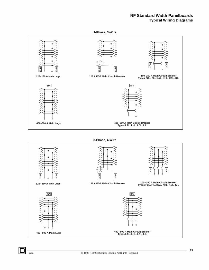
125–250 A Main Lugs 100–250 A Main Circuit BreakerTypes FCL, FIL, KAL, KHL, KCL, KIL
125 A EDB Main Circuit Breaker
400–600 A Main Lugs
S/N S/N
SN
SN
SN
SN
400–600 A Main Circuit BreakerTypes LAL, LHL, LCL, LIL
SN
SN
125–250 A Main Lugs
SN
SN
100–250 A Main Circuit BreakerTypes FCL, FIL, KAL, KHL, KCL, KIL
SN
SN
125 A EDB Main Circuit Breaker
400–600 A Main Lugs
S/N S/N
400–600 A Main Circuit BreakerTypes LAL, LHL, LCL, LIL
1-Phase, 3-Wire
3-Phase, 4-Wire
1311/99 © 1996–1999 Schneider Electric All Rights Reserved
NF Standard Width PanelboardsDimensions
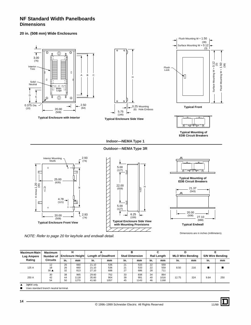
20 in. (508 mm) Wide Enclosures
Maximum Main Lug Ampere
Rating
Maximum Number of
Circuits
HEnclosure Height
ALength of Deadfront
BStud Dimension
CRail Length
DMLO Wire Bending
ES/N Wire Bending
in. mm in. mm in. mm in. mm in. mm in. mm
125 A1218
30 ▲
262632
660660813
21.1021.1027.10
536536688
212127
533533686
222228
559559711
8.50 216 ■ ■
250 A304254
384450
96511181270
29.6035.6041.60
752904
1057
333945
838991
1143
344046
86410161168
12.75 324 9.84 250
▲ 3φ4W only.■ Uses standard branch neutral terminal.
Interior Trim
3.00(76)
A B C
0.375 Dia. (10) 20.00
(508)
Typical Enclosure with Interior
H
Typical Enclosure Side View
5.75(146)
0.25 Mounting (6) Hole Emboss
Typical Front
FlushLock
2.50(64)
Typical Mounting ofEDB Circuit Breakers
Main Lugs
SolidNeutral
ED
Flush Mounting W + 1.50 (38)
Surface Mounting W + 0.12 (3)
Typical Enclosure Side Viewwith Mounting Provisions
H
6.25(159)
22.00(559)
5.00(127)
5.00(127)
Typical Endwall
H m
inus
1.2
0
(
30)
20.00(508)
21.37(543)
4.78(121)
2.93(74)
25.00(635)
2.93(74)
Typical Enclosure Front View
Interior MountingStuds
B
Typical Mounting ofEDB Circuit Breakers
Indoor—NEMA Type 1
Outdoor—NEMA Type 3R
Flu
sh M
ount
ing
W +
1.5
0
(38)
Sur
face
Mou
ntin
g W
+ 0
.12
(3)
27.10(688)
20.00(508)
NOTE: Refer to page 20 for keyhole and endwall detail.Dimensions are in inches (millimeters).
© 1996–1999 Schneider Electric All Rights Reserved14
11/99
NF Standard Width PanelboardsDimensions
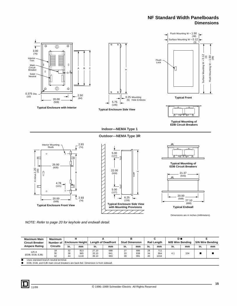
Maximum Main Circuit Breaker Ampere Rating
Maximum Number of
Circuits
HEnclosure Height
ALength of Deadfront
BStud Dimension
CRail Length
D ●M/B Wire Bending
ES/N Wire Bending
in. mm in. mm in. mm in. mm in. mm in. mm
125 A(EDB, EGB, EJB)
183042
323844
813965
1118
27.1033.1039.10
688841993
273339
686838991
283440
711864
10164.1 104 ■ ■
■ Uses standard branch neutral terminal.● EDB, EGB, and EJB main circuit breakers are back-fed. Dimension is from sidewall.
Indoor—NEMA Type 1
Outdoor—NEMA Type 3R
Typical Enclosure with InteriorTypical Enclosure Side View
Typical Front
Typical Mounting ofEDB Circuit Breakers
Interior Trim
3.00(76)
A
D
20.00(508)
2.50(64)
MainCircuit Breaker
SolidNeutral
B C
0.375 Dia. (10)
H
5.75(146)
0.25 Mounting (6) Hole Emboss
FlushLock
Flush Mounting W + 1.50 (38)
Surface Mounting W + 0.12 (3)
Sur
face
Mou
ntin
g W
+ 0
.12
(3)
Flu
sh M
ount
ing
W +
1.5
0
(38)
Typical Enclosure Side Viewwith Mounting Provisions
H
6.25(159)
22.00(559)
5.00(127)
5.00(127)
Typical Endwall
H m
inus
1.2
0
(3
0)
20.00(508)
21.37(543)
4.78(121)
2.93(74)
25.00(635)
2.93(74)
Typical Enclosure Front View
Interior MountingStuds
B
Typical Mounting ofEDB Circuit Breakers
27.10(688)
20.00(508)
Dimensions are in inches (millimeters).
NOTE: Refer to page 20 for keyhole and endwall detail.
1511/99 © 1996–1999 Schneider Electric All Rights Reserved
NF Standard Width PanelboardsDimensions
Maximum Main Circuit Breaker Ampere Rating
Maximum Number of
Circuits
HEnclosure Height
ALength of Deadfront
BStud Dimension
CRail Length
DM/B Wire Bending
ES/N Wire Bending
in. mm in. mm in. mm in. mm in. mm in. mm
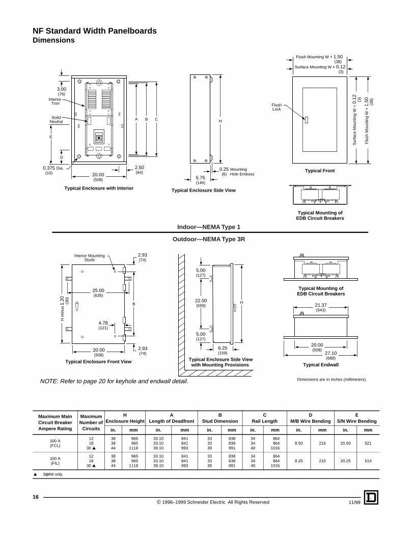
100 A(FCL)
1218
30 ▲
383844
965965
1118
33.1033.1039.10
841841993
333339
838838991
343440
864864
10168.50 216 20.50 521
100 A(FIL)
1218
30 ▲
383844
965965
1118
33.1033.1039.10
841841993
333339
838838991
343440
864864
10168.25 210 20.25 514
▲ 3φ4W only.
Indoor—NEMA Type 1
Outdoor—NEMA Type 3R
Typical Enclosure with Interior Typical Enclosure Side View
Typical Front
Typical Mounting ofEDB Circuit Breakers
Interior Trim
SolidNeutral
3.00(76)
2.50(64)20.00
(508)
0.375 Dia. (10)
D
E
A B C H
5.75(146)
0.25 Mounting (6) Hole Emboss
FlushLock
Flush Mounting W + 1.50 (38)
Surface Mounting W + 0.12 (3)
Flu
sh M
ount
ing
W +
1.5
0
(38)
Sur
face
Mou
ntin
g W
+ 0
.12
(3)
Typical Enclosure Side Viewwith Mounting Provisions
H
6.25(159)
22.00(559)
5.00(127)
5.00(127)
Typical Endwall
H m
inus
1.2
0
(3
0)
20.00(508)
21.37(543)
4.78(121)
2.93(74)
25.00(635)
2.93(74)
Typical Enclosure Front View
Interior MountingStuds
B
Typical Mounting ofEDB Circuit Breakers
27.10(688)
20.00(508)
NOTE: Refer to page 20 for keyhole and endwall detail. Dimensions are in inches (millimeters).
© 1996–1999 Schneider Electric All Rights Reserved16
11/99
NF Standard Width PanelboardsDimensions
Maximum Main Circuit Breaker Ampere Rating
Maximum Number of
Circuits
HEnclosure Height
ALength of Deadfront
BStud Dimension
CRail Length
DM/B Wire Bending
ES/N Wire Bending
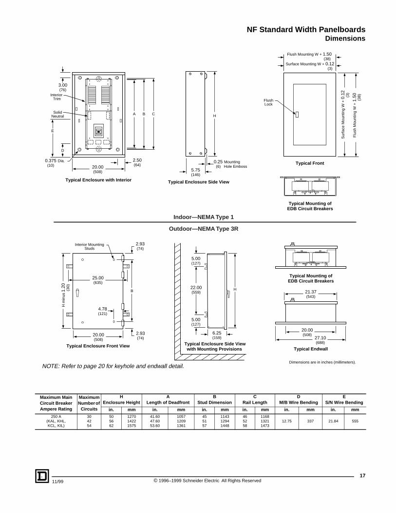
in. mm in. mm in. mm in. mm in. mm in. mm250 A
(KAL, KHL,KCL, KIL)
304254
505662
127014221575
41.6047.6053.60
105712091361
455157
114312941448
465258
116813211473
12.75 337 21.84 555
Indoor—NEMA Type 1
Outdoor—NEMA Type 3R
Typical Enclosure with Interior Typical Enclosure Side View
Typical Front
Typical Mounting ofEDB Circuit Breakers
Interior Trim
SolidNeutral
3.00(76)
2.50(64)20.00
(508)
0.375 Dia. (10)
D
E
A B C H
5.75(146)
0.25 Mounting (6) Hole Emboss
FlushLock
Flush Mounting W + 1.50 (38)
Surface Mounting W + 0.12 (3)
Flu
sh M
ount
ing
W +
1.5
0
(38)
Sur
face
Mou
ntin
g W
+ 0
.12
(3)
Typical Enclosure Side Viewwith Mounting Provisions
H
6.25(159)
22.00(559)
5.00(127)
5.00(127)
Typical Endwall
H m
inus
1.2
0
(3
0)
20.00(508)
21.37(543)
4.78(121)
2.93(74)
25.00(635)
2.93(74)
Typical Enclosure Front View
Interior MountingStuds
B
Typical Mounting ofEDB Circuit Breakers
27.10(688)
20.00(508)
NOTE: Refer to page 20 for keyhole and endwall detail.Dimensions are in inches (millimeters).
1711/99 © 1996–1999 Schneider Electric All Rights Reserved
NF Standard Width PanelboardsDimensions
18
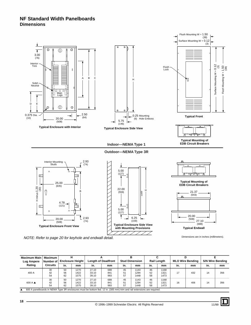
Maximum Main Lug Ampere
Rating
Maximum Number of
Circuits
HEnclosure Height
ALength of Deadfront
BStud Dimension
CRail Length
DMLO Wire Bending
ES/N Wire Bending
in. mm in. mm in. mm in. mm in. mm in. mm
400 A304254
505662
127014221575
27.1033.1039.10
688841993
455157
114312941448
465258
116813211473
17 432 14 356
600 A ▲304254
505662
127014221575
27.1033.1039.10
688841993
455157
114312941448
465258
116813211473
16 406 14 356
▲ 600 A panelboards in NEMA Type 3R enclosures must be bottom fed. 12 in. (305 mm) trim and rail extensions are required.
Indoor—NEMA Type 1
Outdoor—NEMA Type 3R
Interior Trim
3.00(76)
A
2.50(64)20.00
(508)
H
5.75(146)
0.25 Mounting (6) Hole Emboss
FlushLock
D E
B C
0.375 Dia. (10)
Main Lugs
SolidNeutral
Flush Mounting W + 1.50 (38)
Surface Mounting W + 0.12 (3)
Typical Enclosure with Interior Typical Enclosure Side View
Typical Front
Typical Mounting ofEDB Circuit Breakers
Sur
face
Mou
ntin
g W
+ 0
.12
(3)
Flu
sh M
ount
ing
W +
1.5
0
(38)
Typical Enclosure Side Viewwith Mounting Provisions
H
6.25(159)
22.00(559)
5.00(127)
5.00(127)
Typical Endwall
H m
inus
1.2
0
(
30)
20.00(508)
21.37(543)
4.78(121)
2.93(74)
25.00(635)
2.93(74)
Typical Enclosure Front View
Interior MountingStuds
B
Typical Mounting ofEDB Circuit Breakers
27.10(688)
20.00(508)
NOTE: Refer to page 20 for keyhole and endwall detail. Dimensions are in inches (millimeters).
© 1996–1999 Schneider Electric All Rights Reserved 11/99
NF Standard Width PanelboardsDimensions
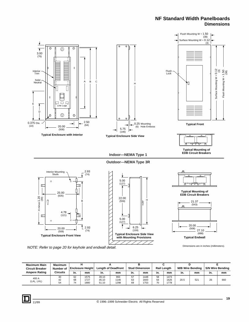
Maximum Main Circuit Breaker Ampere Rating
Maximum Number of
Circuits
HEnclosure Height
ALength of Deadfront
BStud Dimension
CRail Length
DM/B Wire Bending
ES/N Wire Bending
in. mm in. mm in. mm in. mm in. mm in. mm
400 A(LAL, LHL)
304254
626874
157517271880
39.1045.1051.10
99311461298
576369
144816001753
586470
147316261778
20.5 521 26 660
Indoor—NEMA Type 1
Outdoor—NEMA Type 3R
Interior Trim
SolidNeutral A
20.00(508)
H
Line Lugs
5.75(146)
2.50(64) 0.25 Mounting
(6) Hole Emboss
FlushLock
3.00(76)
B C
0.375 Dia. (10)
D
E
Flush Mounting W + 1.50 (38)
Surface Mounting W + 0.12 (3)
Typical Enclosure with Interior Typical Enclosure Side View
Typical Front
Typical Mounting ofEDB Circuit Breakers
Sur
face
Mou
ntin
g W
+ 0
.12
(3)
Flu
sh M
ount
ing
W +
1.5
0
(38)
Typical Enclosure Side Viewwith Mounting Provisions
H
6.25(159)
22.00(559)
5.00(127)
5.00(127)
Typical Endwall
H m
inus
1.2
0
(
30)
20.00(508)
21.37(543)
4.78(121)
2.93(74)
25.00(635)
2.93(74)
Typical Enclosure Front View
Interior MountingStuds
B
Typical Mounting ofEDB Circuit Breakers
27.10(688)
20.00(508)
NOTE: Refer to page 20 for keyhole and endwall detail. Dimensions are in inches (millimeters).
1911/99 © 1996–1999 Schneider Electric All Rights Reserved
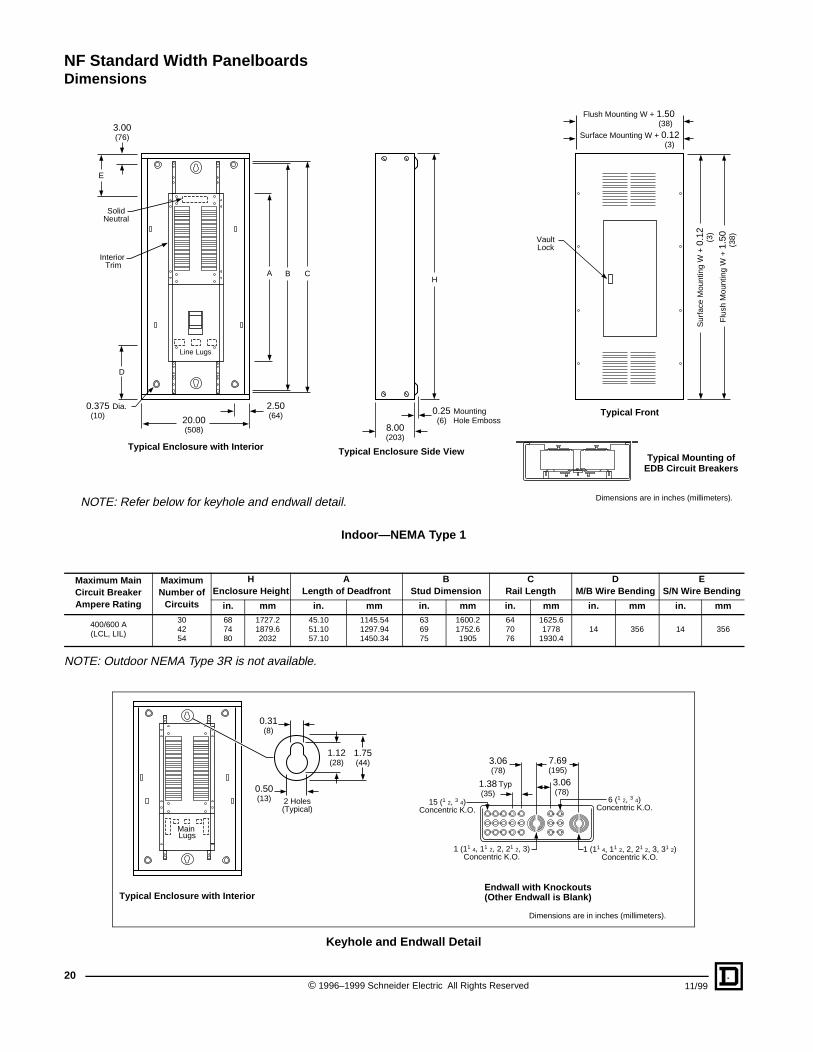
NF Standard Width PanelboardsDimensions
Indoor—NEMA Type 1
NOTE: Outdoor NEMA Type 3R is not available.
Keyhole and Endwall Detail
Maximum Main Circuit Breaker Ampere Rating
Maximum Number of
Circuits
HEnclosure Height
ALength of Deadfront
BStud Dimension
CRail Length
DM/B Wire Bending
ES/N Wire Bending
in. mm in. mm in. mm in. mm in. mm in. mm
400/600 A(LCL, LIL)
304254
687480
1727.21879.62032
45.1051.1057.10
1145.541297.941450.34
636975
1600.21752.61905
647076
1625.61778
1930.414 356 14 356
Interior Trim
SolidNeutral
A
20.00(508)
H
Line Lugs
8.00(203)
2.50(64) 0.25 Mounting
(6) Hole Emboss
VaultLock
3.00(76)
B C
0.375 Dia. (10)
D
E
Flush Mounting W + 1.50 (38)
Surface Mounting W + 0.12 (3)
Typical Enclosure with Interior Typical Enclosure Side View
Typical Front
Typical Mounting ofEDB Circuit Breakers
Sur
face
Mou
ntin
g W
+ 0
.12
(3)
Flu
sh M
ount
ing
W +
1.5
0
(38)
NOTE: Refer below for keyhole and endwall detail. Dimensions are in inches (millimeters).
Typical Enclosure with Interior
7.69(195)
3.06(78)
15 (1 2, 3 4)Concentric K.O.
6 (1 2, 3 4)Concentric K.O.
1 (11 4, 11 2, 2, 21 2, 3)Concentric K.O.
1 (11 4, 11 2, 2, 21 2, 3, 31 2)Concentric K.O.
3.06(78)
1.38 Typ(35)
Endwall with Knockouts(Other Endwall is Blank)
Main Lugs
1.75(44)
1.12(28)
0.31(8)
0.50(13) 2 Holes
(Typical)
Dimensions are in inches (millimeters).
© 1996–1999 Schneider Electric All Rights Reserved20
11/99
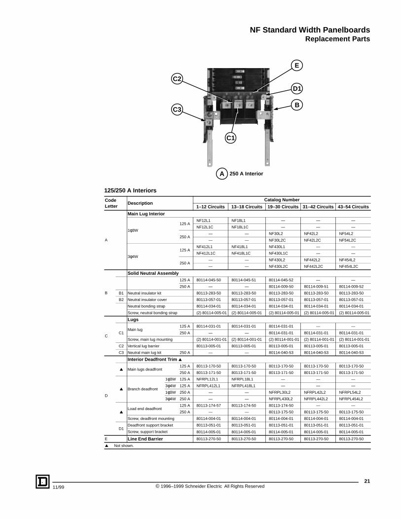
NF Standard Width PanelboardsReplacement Parts
11/99
125/250 A Interiors
CodeLetter
DescriptionCatalog Number
1–12 Circuits 13–18 Circuits 19–30 Circuits 31–42 Circuits 43–54 Circuits
A
Main Lug Interior
1φ3W
125 ANF12L1 NF18L1 — — —
NF12L1C NF18L1C — — —
250 A— — NF30L2 NF42L2 NF54L2
— — NF30L2C NF42L2C NF54L2C
3φ4W
125 ANF412L1 NF418L1 NF430L1 — —
NF412L1C NF418L1C NF430L1C — —
250 A— — NF430L2 NF442L2 NF454L2
— — NF430L2C NF442L2C NF454L2C
B
Solid Neutral Assembly125 A 80114-045-50 80114-045-51 80114-045-52 — —
250 A — — 80114-009-50 80114-009-51 80114-009-52
B1 Neutral insulator kit 80113-283-50 80113-283-50 80113-283-50 80113-283-50 80113-283-50
B2 Neutral insulator cover 80113-057-01 80113-057-01 80113-057-01 80113-057-01 80113-057-01
Neutral bonding strap 80114-034-01 80114-034-01 80114-034-01 80114-034-01 80114-034-01
Screw, neutral bonding strap (2) 80114-005-01 (2) 80114-005-01 (2) 80114-005-01 (2) 80114-005-01 (2) 80114-005-01
C
Lugs
C1Main lug
125 A 80114-031-01 80114-031-01 80114-031-01 — —
250 A — — 80114-031-01 80114-031-01 80114-031-01
Screw, main lug mounting (2) 80114-001-01 (2) 80114-001-01 (2) 80114-001-01 (2) 80114-001-01 (2) 80114-001-01
C2 Vertical lug barrier 80113-005-01 80113-005-01 80113-005-01 80113-005-01 80113-005-01
C3 Neutral main lug kit 250 A — — 80114-040-53 80114-040-53 80114-040-53
D
Interior Deadfront Trim ▲
▲ Main lugs deadfront125 A 80113-170-50 80113-170-50 80113-170-50 80113-170-50 80113-170-50
250 A 80113-171-50 80113-171-50 80113-171-50 80113-171-50 80113-171-50
▲ Branch deadfront
1φ3W 125 A NFRPL12L1 NFRPL18L1 — — —
3φ4W 125 A NFRPL412L1 NFRPL418L1 — — —
1φ3W 250 A — — NFRPL30L2 NFRPL42L2 NFRPL54L2
3φ4W 250 A — — NFRPL430L2 NFRPL442L2 NFRPL454L2
▲Load end deadfront
125 A 80113-174-57 80113-174-50 80113-174-50 — —
250 A — — 80113-175-50 80113-175-50 80113-175-50
Screw, deadfront mounting 80114-004-01 80114-004-01 80114-004-01 80114-004-01 80114-004-01
D1Deadfront support bracket 80113-051-01 80113-051-01 80113-051-01 80113-051-01 80113-051-01
Screw, support bracket 80114-005-01 80114-005-01 80114-005-01 80114-005-01 80114-005-01
E Line End Barrier 80113-270-50 80113-270-50 80113-270-50 80113-270-50 80113-270-50
▲ Not shown.
250 A Interior
C2
E
C3
C1
D1
B
A
21© 1996–1999 Schneider Electric All Rights Reserved
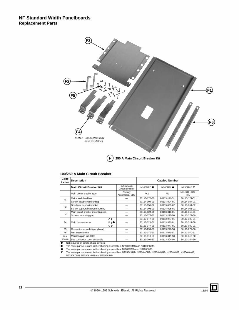
NF Standard Width PanelboardsReplacement Parts
22
100/250 A Main Circuit BreakerCode Letter
Description Catalog Number
Main Circuit Breaker Kit 125 A Main Circuit Breaker
N100MFC ■ N100MFI ◆ N250MKC ▼
Main circuit breaker typeFactory
Assembled, EDBFCL FIL
KAL, KHL, KCL, KIL
F1Mains end deadfront — 80113-170-60 80113-171-51 80113-171-51
Screw, deadfront mounting — 80114-004-01 80114-004-01 80114-004-01
F2Deadfront support bracket — 80113-051-02 80113-051-02 80113-051-02
Screw, support bracket mounting — 80114-005-01 80114-005-01 80114-005-01
F3Main circuit breaker mounting pan — 80113-324-01 80113-318-01 80113-318-01
Screws, mounting pan — 80113-277-50 80113-277-50 80113-277-50
F4 Main bus connector
A φ — 80113-077-01 80113-077-01 80113-080-01
B φ ● — 80113-321-01 80113-321-01 80113-311-50
C φ — 80113-077-01 80113-077-01 80113-080-01
F5 Connector screw kit (per phase) — 80113-294-50 80113-279-50 80113-279-50
F6 Rail extension kit — 80113-070-51 80113-070-51 80113-070-51
Not shown
Mounting pan insulator — 80113-319-50 80113-319-50 80113-319-50
Bus connector cover assembly — 80113-304-50 80113-304-50 80113-304-50
● Not required on single-phase devices.■ The same parts are used in the following assemblies: N2100FCMB and N3100FCMB.◆ The same parts are used in the following assemblies: N2100FIMB and N3100FIMB.▼ The same parts are used in the following assemblies: N2250KAMB, N2250KCMB, N2250KHMB, N2250KIMB, N3250KAMB,
N3250KCMB, N3250KHMB and N3250KIMB.
F3
F2
F1
F6
F5
F4
250 A Main Circuit Breaker KitF
NOTE: Connectors may have insulators.
© 1996–1999 Schneider Electric All Rights Reserved 11/99
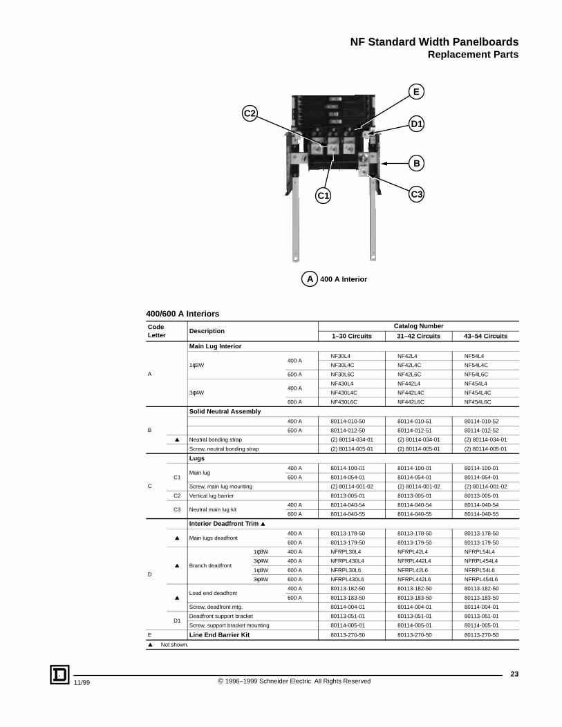
NF Standard Width PanelboardsReplacement Parts
11/99
400/600 A Interiors
CodeLetter
DescriptionCatalog Number
1–30 Circuits 31–42 Circuits 43–54 Circuits
A
Main Lug Interior
1φ3W400 A
NF30L4 NF42L4 NF54L4
NF30L4C NF42L4C NF54L4C
600 A NF30L6C NF42L6C NF54L6C
3φ4W400 A
NF430L4 NF442L4 NF454L4
NF430L4C NF442L4C NF454L4C
600 A NF430L6C NF442L6C NF454L6C
B
Solid Neutral Assembly
400 A 80114-010-50 80114-010-51 80114-010-52
600 A 80114-012-50 80114-012-51 80114-012-52
▲ Neutral bonding strap (2) 80114-034-01 (2) 80114-034-01 (2) 80114-034-01
Screw, neutral bonding strap (2) 80114-005-01 (2) 80114-005-01 (2) 80114-005-01
C
Lugs
C1Main lug
400 A 80114-100-01 80114-100-01 80114-100-01
600 A 80114-054-01 80114-054-01 80114-054-01
Screw, main lug mounting (2) 80114-001-02 (2) 80114-001-02 (2) 80114-001-02
C2 Vertical lug barrier 80113-005-01 80113-005-01 80113-005-01
C3 Neutral main lug kit 400 A 80114-040-54 80114-040-54 80114-040-54
600 A 80114-040-55 80114-040-55 80114-040-55
D
Interior Deadfront Trim ▲
▲ Main lugs deadfront400 A 80113-178-50 80113-178-50 80113-178-50
600 A 80113-179-50 80113-179-50 80113-179-50
▲ Branch deadfront
1φ3W 400 A NFRPL30L4 NFRPL42L4 NFRPL54L4
3φ4W 400 A NFRPL430L4 NFRPL442L4 NFRPL454L4
1φ3W 600 A NFRPL30L6 NFRPL42L6 NFRPL54L6
3φ4W 600 A NFRPL430L6 NFRPL442L6 NFRPL454L6
▲Load end deadfront
400 A 80113-182-50 80113-182-50 80113-182-50
600 A 80113-183-50 80113-183-50 80113-183-50
Screw, deadfront mtg. 80114-004-01 80114-004-01 80114-004-01
D1Deadfront support bracket 80113-051-01 80113-051-01 80113-051-01
Screw, support bracket mounting 80114-005-01 80114-005-01 80114-005-01
E Line End Barrier Kit 80113-270-50 80113-270-50 80113-270-50
▲ Not shown.
400 A Interior
C2
E
C1
D1
C3
B
A
23© 1996–1999 Schneider Electric All Rights Reserved
NF Standard Width PanelboardsReplacement Parts
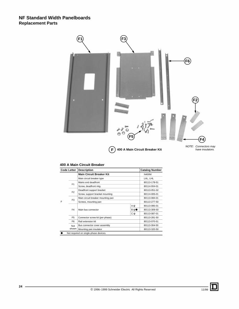
24
400 A Main Circuit BreakerCode Letter Description Catalog Number
F
Main Circuit Breaker Kit N400M
Main circuit breaker type LAL, LHL
F1Mains end deadfront 80113-178-51
Screw, deadfront mtg. 80114-004-01
F2Deadfront support bracket 80113-051-02
Screw, support bracket mounting 80114-005-01
F3Main circuit breaker mounting pan 80113-084-01
Screws, mounting pan 80113-277-50
F4 Main bus connector
A φ 80113-085-01
B φ ● 80113-309-50
C φ 80113-087-01
F5 Connector screw kit (per phase) 80113-281-50
F6 Rail extension kit 80113-070-51
Not shown
Bus connector cover assembly 80113-304-50
Mounting pan insulator 80113-320-50
● Not required on single-phase devices.
400 A Main Circuit Breaker Kit
F2
F4F5
F3F1
F6
FNOTE: Connectors may
have insulators.
© 1996–1999 Schneider Electric All Rights Reserved 11/99
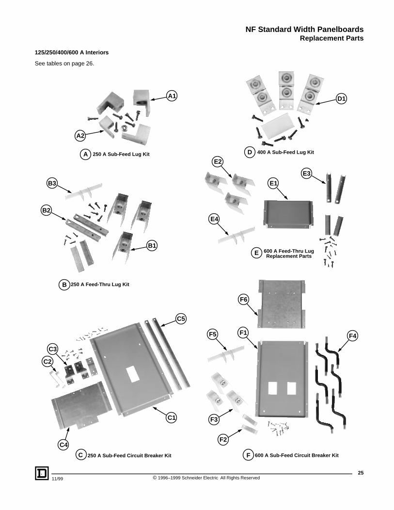
NF Standard Width PanelboardsReplacement Parts
125/250/400/600 A Interiors
See tables on page 26.
250 A Sub-Feed Lug Kit 400 A Sub-Feed Lug Kit
600 A Feed-Thru LugReplacement Parts
250 A Sub-Feed Circuit Breaker Kit 600 A Sub-Feed Circuit Breaker Kit
250 A Feed-Thru Lug Kit
A1
A2
B2
C5
C3
C1
E1
E2
E4
F4F1F5
F6
C2
E3
C4
B1
B3
D1
F3
F2
A D
B
C F
E
2511/99 © 1996–1999 Schneider Electric All Rights Reserved
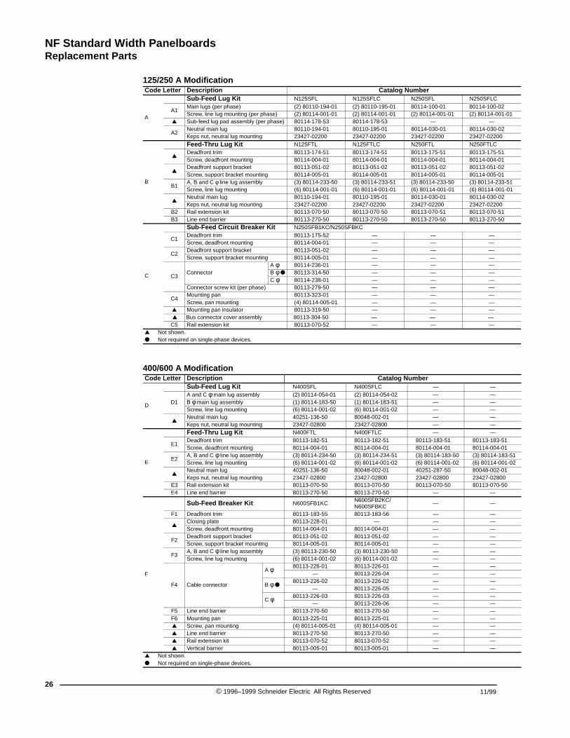
NF Standard Width PanelboardsReplacement Parts
26
125/250 A ModificationCode Letter Description Catalog Number
A
Sub-Feed Lug Kit N125SFL N125SFLC N250SFL N250SFLC
A1Main lugs (per phase) (2) 80110-194-01 (2) 80110-195-01 80114-100-01 80114-100-02Screw, line lug mounting (per phase) (2) 80114-001-01 (2) 80114-001-01 (2) 80114-001-01 (2) 80114-001-01
▲ Sub-feed lug pad assembly (per phase) 80114-178-53 80114-178-53 — —
A2Neutral main lug 80110-194-01 80110-195-01 80114-030-01 80114-030-02Keps nut, neutral lug mounting 23427-02200 23427-02200 23427-02200 23427-02200
B
Feed-Thru Lug Kit N125FTL N125FTLC N250FTL N250FTLC
▲Deadfront trim 80113-174-51 80113-174-51 80113-175-51 80113-175-51Screw, deadfront mounting 80114-004-01 80114-004-01 80114-004-01 80114-004-01
▲Deadfront support bracket 80113-051-02 80113-051-02 80113-051-02 80113-051-02Screw, support bracket mounting 80114-005-01 80114-005-01 80114-005-01 80114-005-01
B1A, B and C φ line lug assembly (3) 80114-233-50 (3) 80114-233-51 (3) 80114-233-50 (3) 80114-233-51Screw, line lug mounting (6) 80114-001-01 (6) 80114-001-01 (6) 80114-001-01 (6) 80114-001-01
▲Neutral main lug 80110-194-01 80110-195-01 80114-030-01 80114-030-02Keps nut, neutral lug mounting 23427-02200 23427-02200 23427-02200 23427-02200
B2 Rail extension kit 80113-070-50 80113-070-50 80113-070-51 80113-070-51B3 Line end barrier 80113-270-50 80113-270-50 80113-270-50 80113-270-50
C
Sub-Feed Circuit Breaker Kit N250SFB1KC/N250SFBKC
C1Deadfront trim 80113-175-52 — — —Screw, deadfront mounting 80114-004-01 — — —
C2Deadfront support bracket 80113-051-02 — — —Screw, support bracket mounting 80114-005-01 — — —
C3Connector
A φ 80114-236-01 — — —B φ ● 80113-314-50 — — —C φ 80114-238-01 — — —
Connector screw kit (per phase) 80113-279-50 — — —
C4Mounting pan 80113-323-01 — — —Screw, pan mounting (4) 80114-005-01 — — —
▲ Mounting pan insulator 80113-319-50 — — — ▲ Bus connector cover assembly 80113-304-50 — — —C5 Rail extension kit 80113-070-52 — — —
▲ Not shown.● Not required on single-phase devices.
400/600 A ModificationCode Letter Description Catalog Number
D
Sub-Feed Lug Kit N400SFL N400SFLC — —
D1A and C φ main lug assembly (2) 80114-054-01 (2) 80114-054-02 — —B φ main lug assembly (1) 80114-183-50 (1) 80114-183-51 — —Screw, line lug mounting (6) 80114-001-02 (6) 80114-001-02 — —
▲Neutral main lug 40251-136-50 80048-002-01 — —Keps nut, neutral lug mounting 23427-02800 23427-02800 — —
E
Feed-Thru Lug Kit N400FTL N400FTLC — —
E1Deadfront trim 80113-182-51 80113-182-51 80113-183-51 80113-183-51Screw, deadfront mounting 80114-004-01 80114-004-01 80114-004-01 80114-004-01
E2A, B and C φ line lug assembly (3) 80114-234-50 (3) 80114-234-51 (3) 80114-183-50 (3) 80114-183-51Screw, line lug mounting (6) 80114-001-02 (6) 80114-001-02 (6) 80114-001-02 (6) 80114-001-02
▲Neutral main lug 40251-136-50 80048-002-01 40251-287-50 80048-002-01Keps nut, neutral lug mounting 23427-02800 23427-02800 23427-02800 23427-02800
E3 Rail extension kit 80113-070-50 80113-070-50 80113-070-50 80113-070-50E4 Line end barrier 80113-270-50 80113-270-50 — —
F
Sub-Feed Breaker Kit N600SFB1KCN600SFB2KC/N600SFBKC
— —
F1 Deadfront trim 80113-183-55 80113-183-56 — —
▲Closing plate 80113-228-01 — — —Screw, deadfront mounting 80114-004-01 80114-004-01 — —
F2Deadfront support bracket 80113-051-02 80113-051-02 — —Screw, support bracket mounting 80114-005-01 80114-005-01 — —
F3A, B and C φ line lug assembly (3) 80113-230-50 (3) 80113-230-50 — —Screw, line lug mounting (6) 80114-001-02 (6) 80114-001-02 — —
F4 Cable connector
A φ 80113-226-01 80113-226-01 — —— 80113-226-04 — —
B φ ●80113-226-02 80113-226-02 — —
— 80113-226-05 — —
C φ 80113-226-03 80113-226-03 — —— 80113-226-06 — —
F5 Line end barrier 80113-270-50 80113-270-50 — —F6 Mounting pan 80113-225-01 80113-225-01 — —▲ Screw, pan mounting (4) 80114-005-01 (4) 80114-005-01 — —▲ Line end barrier 80113-270-50 80113-270-50 — —▲ Rail extension kit 80113-070-52 80113-070-52 — —▲ Vertical barrier 80113-005-01 80113-005-01 — —
▲ Not shown.● Not required on single-phase devices.
© 1996–1999 Schneider Electric All Rights Reserved 11/99
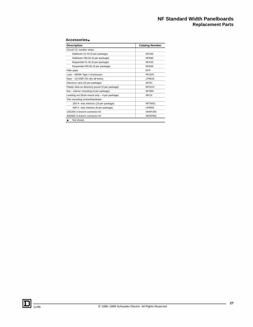
NF Standard Width PanelboardsReplacement Parts
11/99
Accessories▲
Description Catalog NumberCircuit I.D. number strips:
Odd/even #1-42 (5 per package) NF42D
Odd/even #55-84 (5 per package) NF84D
Sequential #1-42 (5 per package) NF42S
Sequential #55-84 (5 per package) NF84S
Filler plate EFP
Lock – NEMA Type 1 enclosures PK22FL
Keys – (2) NSR-251 (for all locks) LP9618
Directory card (10 per package) NFDC
Plastic stick-on directory pouch (5 per package) NFDCH
Nut – interior mounting (4 per package) NFNIM
Leveling nut (flush mount only – 4 per package) NFLN
Trim mounting screws/hardware:
250 A max interiors (10 per package) NFTMS1
600 A max interiors (8 per package) LP9502
125/250 A branch connector kit SKNF250
400/600 A branch connector kit SKNF600
▲ Not shown.
27© 1996–1999 Schneider Electric All Rights Reserved
NF Column Width PanelboardsApplication Data
28
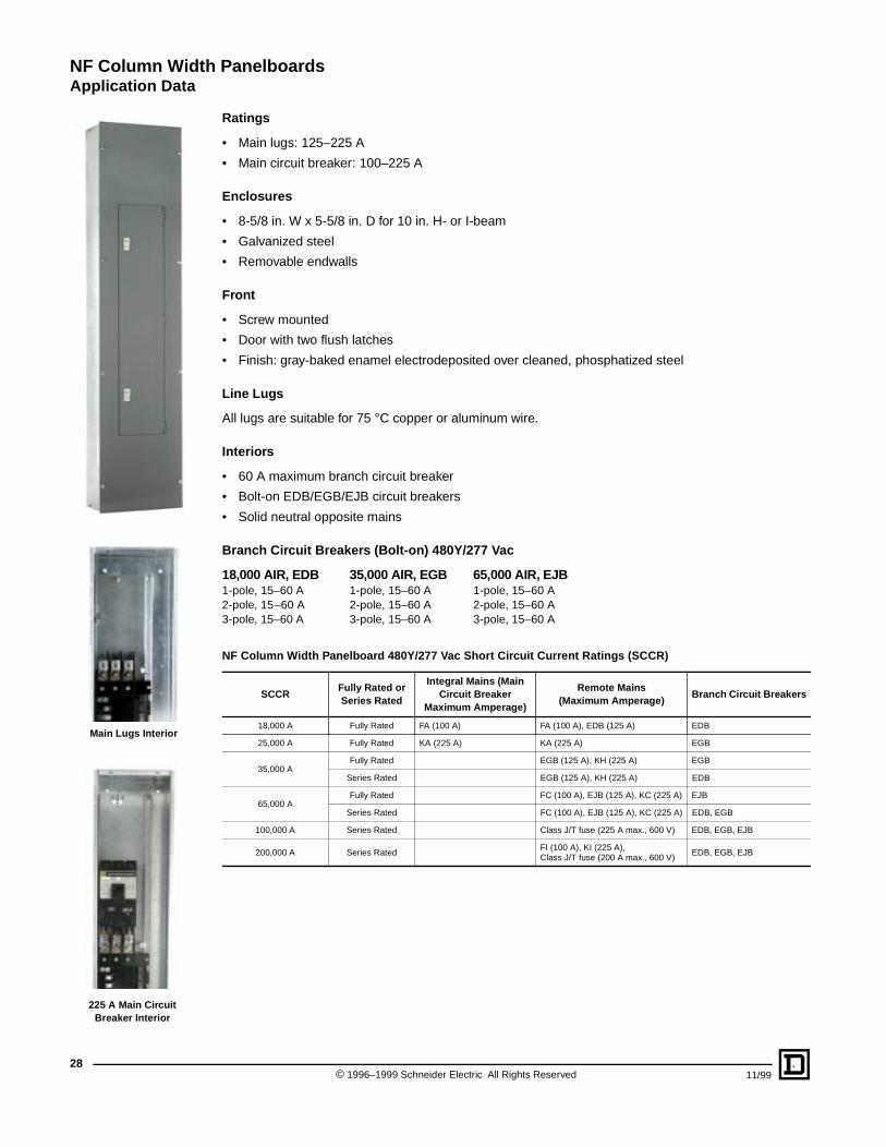
Main Lugs Interior
225 A Main Circuit Breaker Interior
Ratings
• Main lugs: 125–225 A
• Main circuit breaker: 100–225 A
Enclosures
• 8-5/8 in. W x 5-5/8 in. D for 10 in. H- or I-beam
• Galvanized steel
• Removable endwalls
Front
• Screw mounted
• Door with two flush latches
• Finish: gray-baked enamel electrodeposited over cleaned, phosphatized steel
Line Lugs
All lugs are suitable for 75 °C copper or aluminum wire.
Interiors
• 60 A maximum branch circuit breaker
• Bolt-on EDB/EGB/EJB circuit breakers
• Solid neutral opposite mains
Branch Circuit Breakers (Bolt-on) 480Y/277 Vac
18,000 AIR, EDB 35,000 AIR, EGB 65,000 AIR, EJB1-pole, 15–60 A 1-pole, 15–60 A 1-pole, 15–60 A2-pole, 15–60 A 2-pole, 15–60 A 2-pole, 15–60 A3-pole, 15–60 A 3-pole, 15–60 A 3-pole, 15–60 A
NF Column Width Panelboard 480Y/277 Vac Short Circuit Current Ratings (SCCR)
SCCRFully Rated or Series Rated
Integral Mains (Main Circuit Breaker
Maximum Amperage)
Remote Mains (Maximum Amperage)
Branch Circuit Breakers
18,000 A Fully Rated FA (100 A) FA (100 A), EDB (125 A) EDB
25,000 A Fully Rated KA (225 A) KA (225 A) EGB
35,000 AFully Rated EGB (125 A), KH (225 A) EGB
Series Rated EGB (125 A), KH (225 A) EDB
65,000 AFully Rated FC (100 A), EJB (125 A), KC (225 A) EJB
Series Rated FC (100 A), EJB (125 A), KC (225 A) EDB, EGB
100,000 A Series Rated Class J/T fuse (225 A max., 600 V) EDB, EGB, EJB
200,000 A Series RatedFI (100 A), KI (225 A), Class J/T fuse (200 A max., 600 V)
EDB, EGB, EJB
© 1996–1999 Schneider Electric All Rights Reserved 11/99
NF Column Width PanelboardsApplication Data
11/99 ©
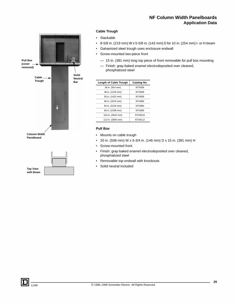
Solid Neutral Bar
Cable Trough
Pull Box (coverremoved)
Column Width Panelboard
Top View with Beam
Cable Trough
• Stackable
• 8-5/8 in. (219 mm) W x 5-5/8 in. (143 mm) D for 10 in. (254 mm) I- or H-beam
• Galvanized steel trough uses enclosure endwall
• Screw-mounted two-piece front
— 15 in. (381 mm) long top piece of front removable for pull box mounting
— Finish: gray-baked enamel electrodeposited over cleaned, phosphatized steel
Pull Box
• Mounts on cable trough
• 20 in. (508 mm) W x 5-3/4 in. (146 mm) D x 15 in. (381 mm) H
• Screw-mounted front
• Finish: gray-baked enamel electrodeposited over cleaned, phosphatized steel
• Removable top endwall with knockouts
• Solid neutral included
Length of Cable Trough Catalog No.
36 in. (914 mm) NTX836
48 in. (1219 mm) NTX848
56 in. (1422 mm) NTX856
66 in. (1676 mm) NTX866
84 in. (2134 mm) NTX884
96 in. (2438 mm) NTX896
104 in. (2642 mm) NTX8104
112 in. (2845 mm) NTX8112
29 1996–1999 Schneider Electric All Rights Reserved
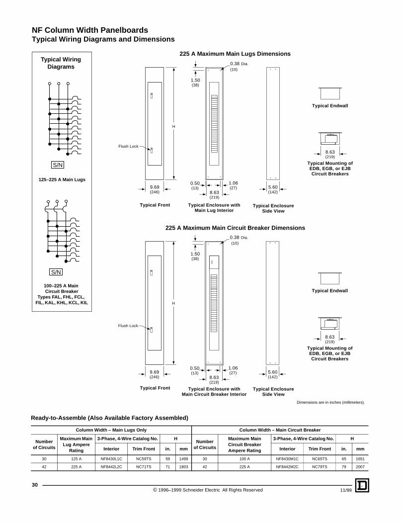
NF Column Width PanelboardsTypical Wiring Diagrams and Dimensions
30
S/N
100–225 A Main Circuit Breaker
Types FAL, FHL, FCL, FIL, KAL , KHL, KCL, KIL
Typical Wiring Diagrams
S/N
125–225 A Main Lugs
Ready-to-Assemble (Al
Column W
Number of Circuits
Maximum Main Lug Am pere
Rating
30 125 A
42 225 A
225 A Maximum Main Lugs Dimensions
225 A Maximum Main Circuit Breaker Dimensions
Flush Lock
H
9.69(246)
5.60(142)8.63
(219)
8.63(219)
1.06(27)
0.50(13)
1.50(38)
0.38 Dia.(10)
Typical Front Typical Enclosure withMain Lug Interior
Typical EnclosureSide View
Typical Mounting ofEDB, EGB, or EJBCircuit Breakers
Typical Endwall
Flush Lock
H
9.69(246)
5.60(142)8.63
(219)
8.63(219)
1.06(27)
0.50(13)
1.50(38)
0.38 Dia. (10)
Typical Front Typical Enclosure withMain Circuit Breaker Interior
Typical EnclosureSide View
Typical Mounting ofEDB, EGB, or EJBCircuit Breakers
Typical Endwall
so Available Factory Assembled)
Dimensions are in inches (millimeters).
© 1996–1999 Schneider Electric All Rights Reserved 11/99
idth – Main L ugs Only Column Width – Main Ci rcuit Bre aker
3-Phase, 4-Wire Catalog No. HNumber
of Circuits
Maxim um Main Circuit Bre aker Amp ere Rating
3-Phase, 4-Wire Catalog No. H
Interior Trim Front in. mm Interior Trim Front in. mm
NF8430L1C NC59TS 59 1499 30 100 A NF8430M1C NC65TS 65 1651
NF8442L2C NC71TS 71 1803 42 225 A NF8442M2C NC79TS 79 2007
NF Column Width PanelboardsReplacement Parts
11/99
Description Catalog Number
NF column width branch connector kit SKNFCW
30 circuit main lug deadfront 80113-372-51
42 circuit main lug deadfront 80113-372-52
30 circuit main circuit breaker deadfront 80113-372-53
42 circuit main circuit breaker deadfront 80113-372-54
Line lug 40251-162-50
NF column width enclosure endwall 80113-341-01
31© 1996–1999 Schneider Electric All Rights Reserved
Catalog No. 1670CT9601R7/99 November 1999 replaces 1670CT9601R5/97 dated 12/97 and 1670SB9601 dated 1/97.
NF Circuit Breaker Panelboards
Square D Company252 North TippecanoePeru, IN 469701-888-Square D(1-888-778-2733)www.squared.com
Schneider Canada Inc.19 Waterman Avenue, M4B 1 Y2Toronto, Ontario(416) 752-8020www.schneider.ca