NEW Spatial referencing presentation (2010) Richard · PDF filecoordinates (φ,λ)...
61
Spatial referencing An overview Richard Knippers
Transcript of NEW Spatial referencing presentation (2010) Richard · PDF filecoordinates (φ,λ)...
Spatial referencing
An overview
Richard Knippers
Learning instructions
Learning activities:
� Literature: ITC Core textbook, Chapter 3.1 on Spatial Referencing.
� Website: http://kartoweb.itc.nl/geometrics
� Exercise: Spatial referencing (ArcMap10)
Questions: Blackboard Discussion Board
Main objectives
� Understand the relevance and actual use of reference surfaces, coordinate systems, and coordinate transformations in mapping.
� Describe and differentiate between coordinate systems and map projections.
� Grasp the logic of map projection equations and the principles of transforming maps from one projection system to another.
Contents
� Spatial reference surfaces and datums
� The Geoid – vertical (height) datum
� The Ellipsoid – horizontal (geodetic) datum
� Local and global datums
� Map projections
� Classification of map projections
� Map projection selection
� Map coordinate systems (e.g. UTM)
� Coordinate transformations
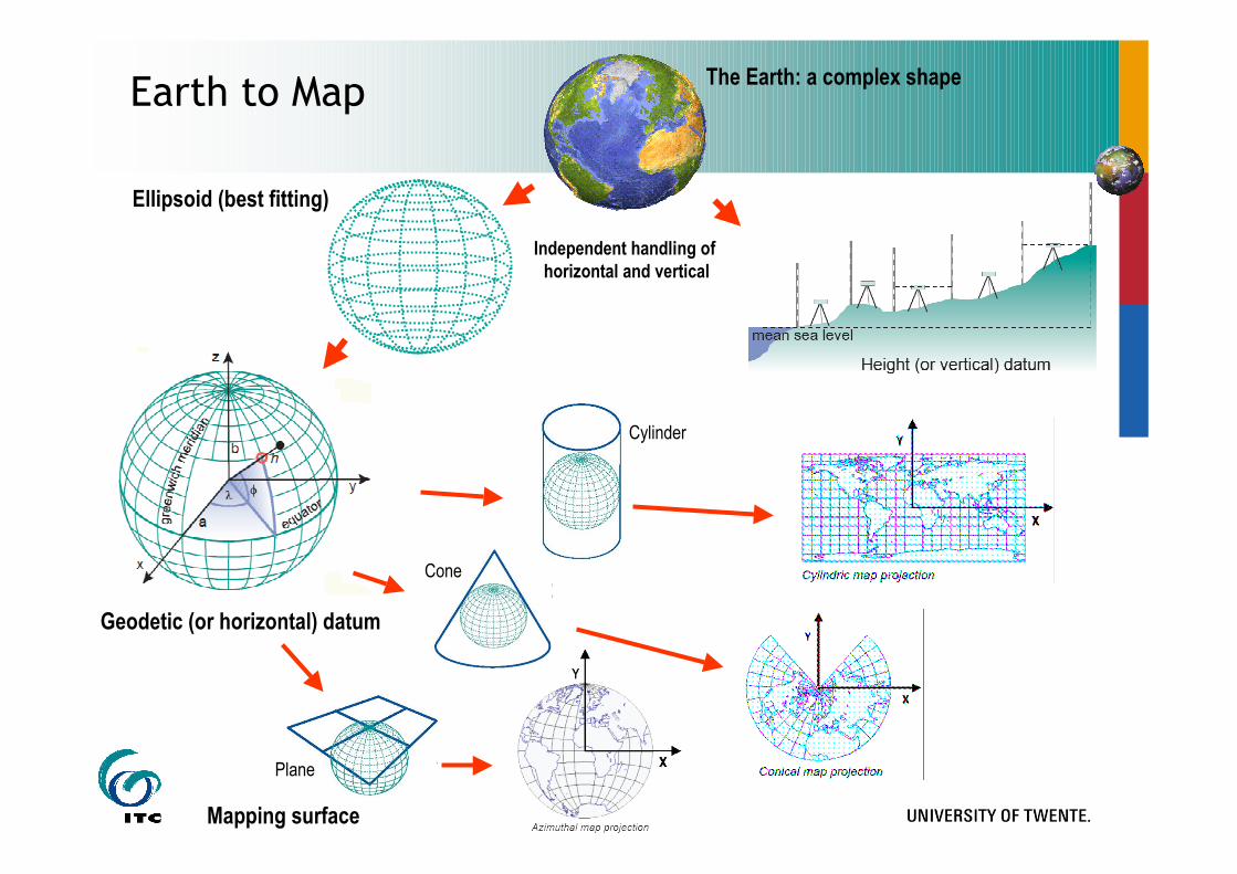
Cone
Plane
Ellipsoid (best fitting)
Geodetic (or horizontal) datum
The Earth: a complex shape
Mapping surface
Independent handling of
horizontal and vertical
Cylinder
Earth to Map
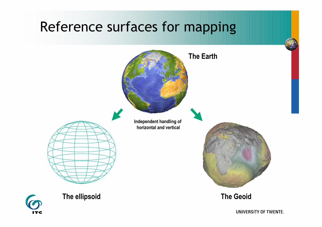
The ellipsoid
The Earth
Independent handling of
horizontal and vertical
The Geoid
Reference surfaces for mapping
Spatial reference surface -
The Geoid
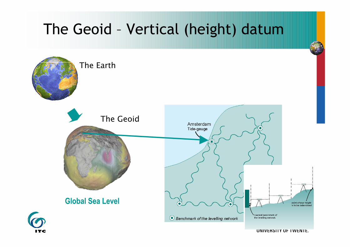
The Geoid – Vertical (height) datum
The Earth
The Geoid
Global Sea Level
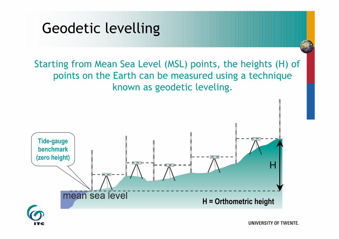
Starting from Mean Sea Level (MSL) points, the heights (H) of points on the Earth can be measured using a technique
known as geodetic leveling.
Geodetic levelling
H = Orthometric height
H
Tide-gauge
benchmark
(zero height)
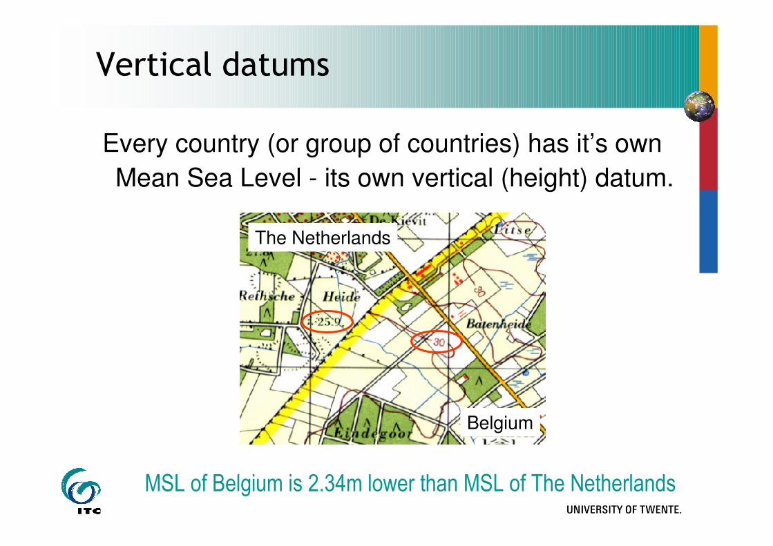
Vertical datums
Every country (or group of countries) has it’s own
Mean Sea Level - its own vertical (height) datum.
The Netherlands
Belgium
MSL of Belgium is 2.34m lower than MSL of The Netherlands
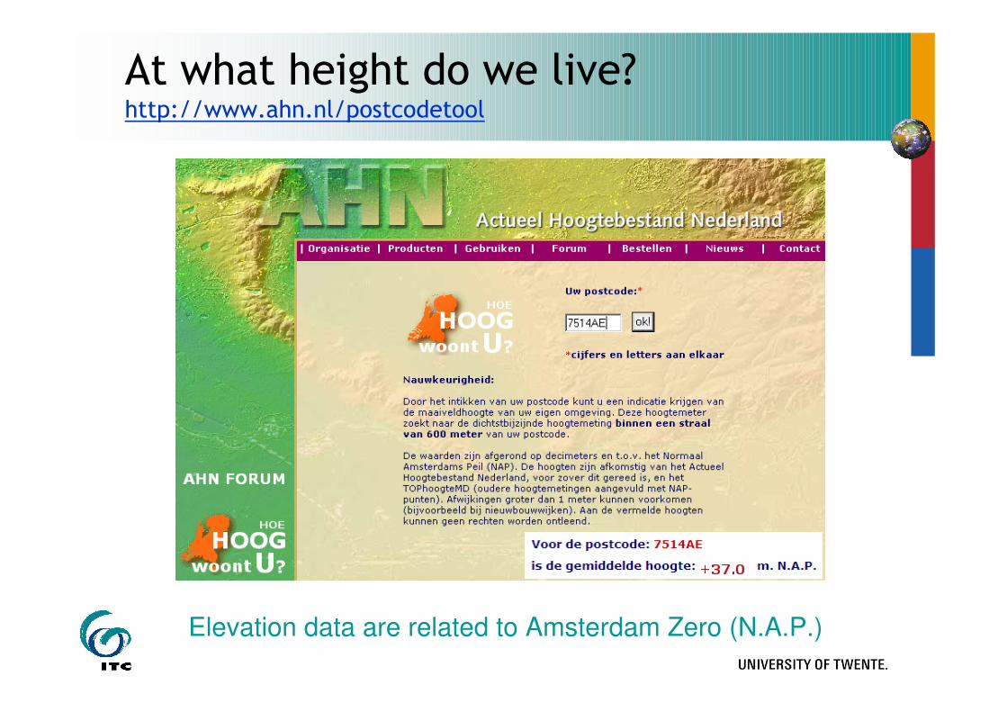
At what height do we live?http://www.ahn.nl/postcodetool
Elevation data are related to Amsterdam Zero (N.A.P.)
HNAP = 37m
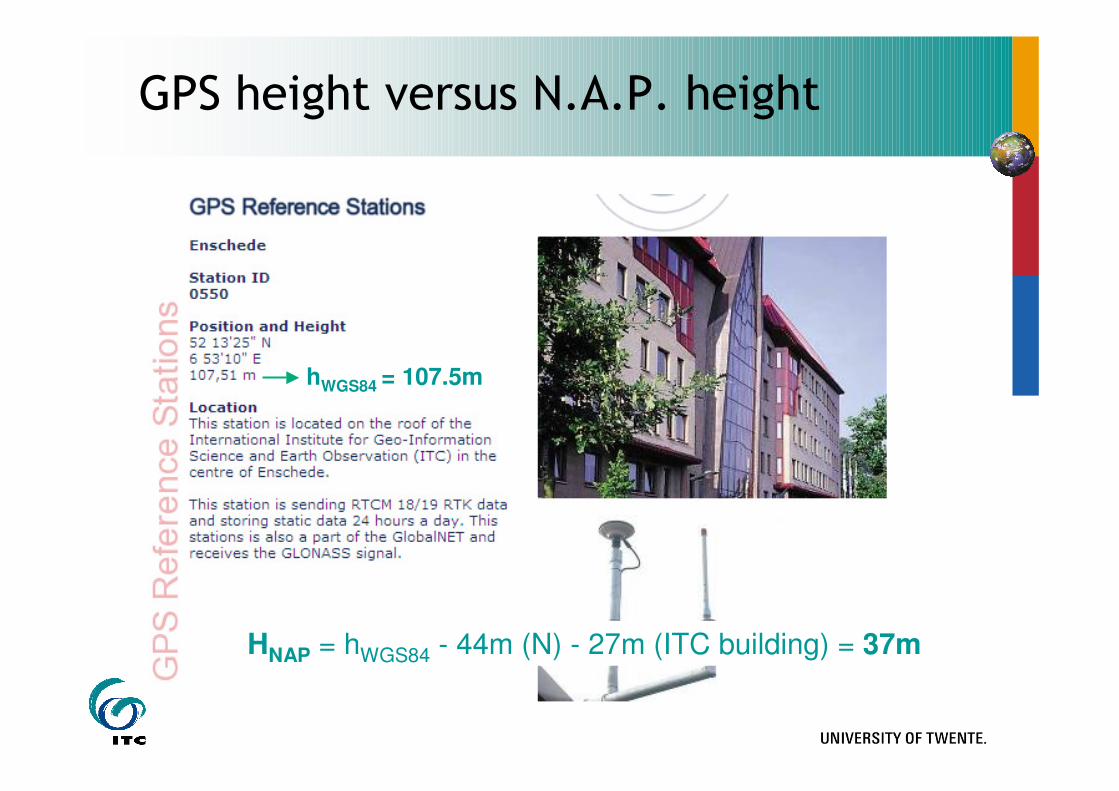
GPS height versus N.A.P. height
hWGS84 = 107.5m
HNAP = hWGS84 - 44m (N) - 27m (ITC building) = 37m
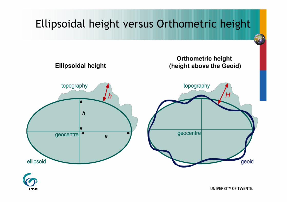
Ellipsoidal heightOrthometric height
(height above the Geoid)
Ellipsoidal height versus Orthometric height
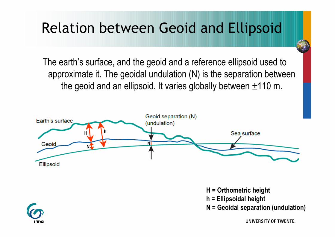
Relation between Geoid and Ellipsoid
The earth’s surface, and the geoid and a reference ellipsoid used to
approximate it. The geoidal undulation (N) is the separation between
the geoid and an ellipsoid. It varies globally between ±110 m.
N
H h
N
H = Orthometric height
h = Ellipsoidal height
N = Geoidal separation (undulation)
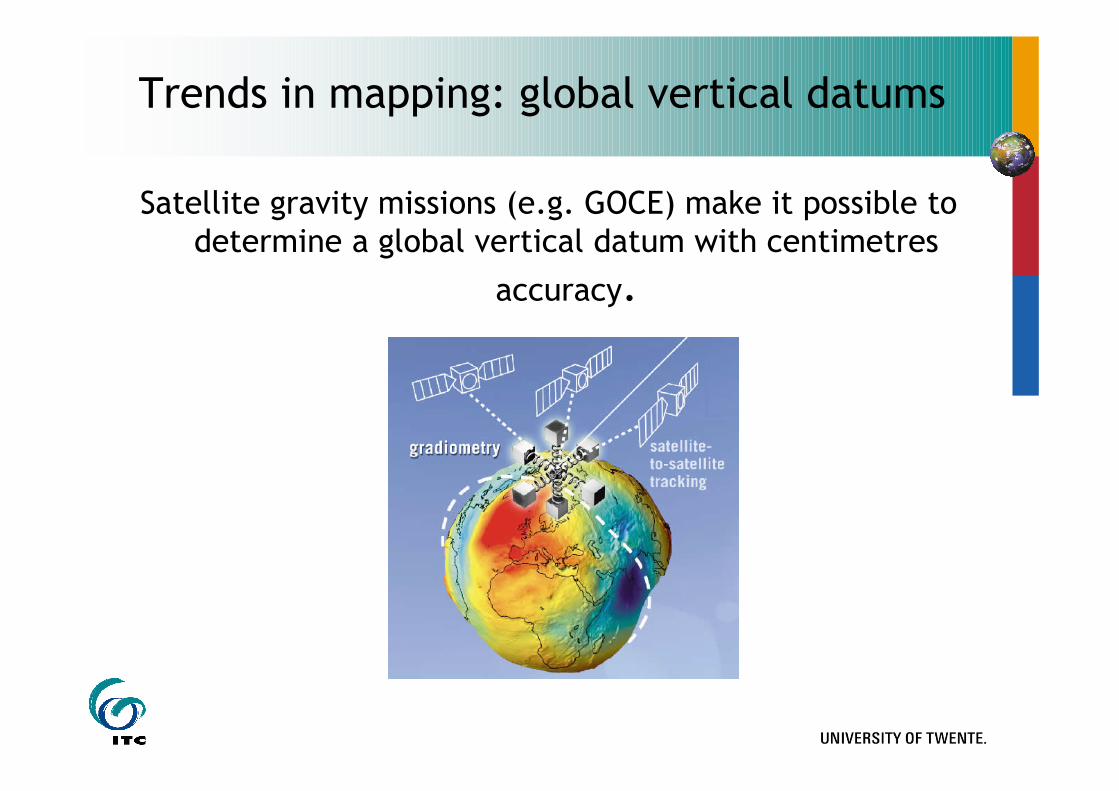
Trends in mapping: global vertical datums
Satellite gravity missions (e.g. GOCE) make it possible to determine a global vertical datum with centimetres
accuracy.
Spatial reference surface -
The Ellipsoid
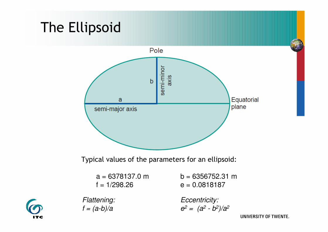
The Ellipsoid
Typical values of the parameters for an ellipsoid:
a = 6378137.0 m b = 6356752.31 m
f = 1/298.26 e = 0.0818187
Flattening: Eccentricity:
f = (a-b)/a e2 = (a2 - b2)/a2
18
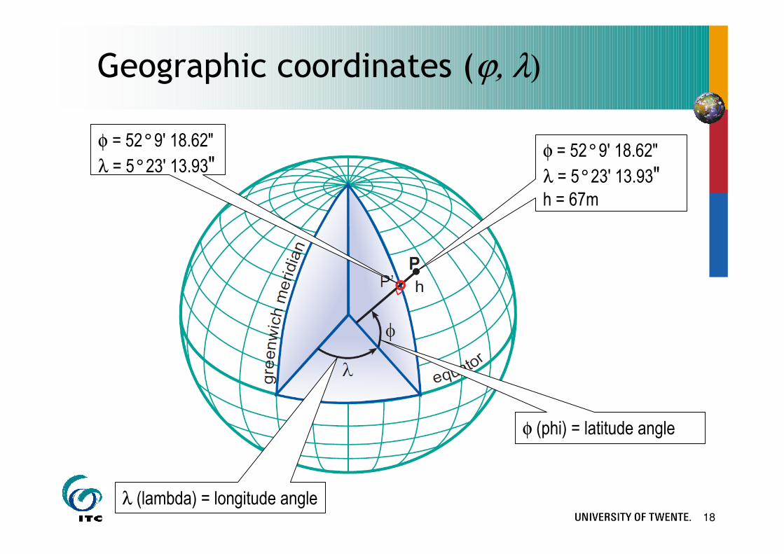
Geographic coordinates (ϕ, λ)
φ = 52°9' 18.62"
λ = 5°23' 13.93"φ = 52°9' 18.62"
λ = 5°23' 13.93"h = 67m
φ (phi) = latitude angle
λ (lambda) = longitude angle

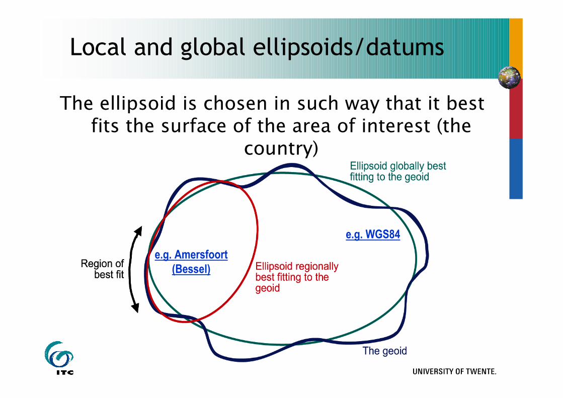
Local and global ellipsoids/datums
The ellipsoid is chosen in such way that it best fits the surface of the area of interest (the
country)
e.g. WGS84
e.g. Amersfoort
(Bessel)
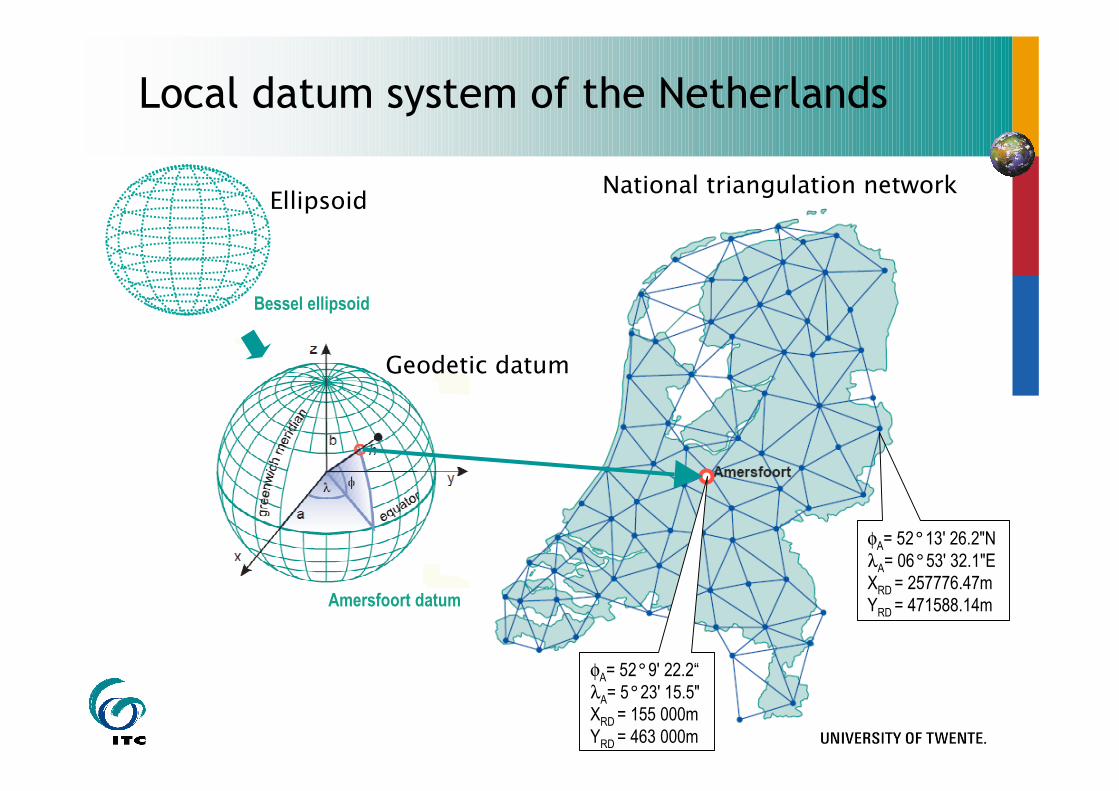
Local datum system of the Netherlands
Ellipsoid
Bessel ellipsoid
Amersfoort datum
National triangulation network
φA= 52°13' 26.2"N
λA= 06°53' 32.1"E
XRD = 257776.47m
YRD = 471588.14m
Geodetic datum
φA= 52°9' 22.2“
λA= 5°23' 15.5"
XRD = 155 000m
YRD = 463 000m
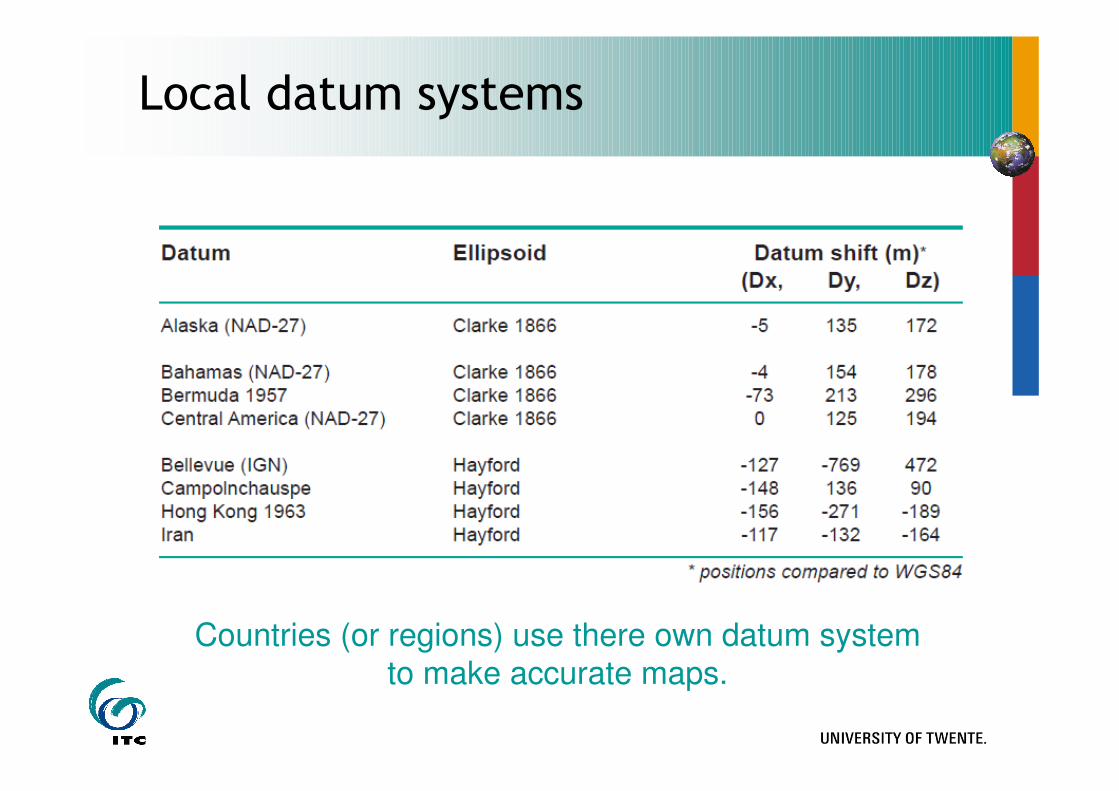
Local datum systems
Countries (or regions) use there own datum system to make accurate maps.
Local and global ellipsoids/datums
The ellipsoid is chosen in such way that it best fits the surface of the area of interest (the
country)
e.g. WGS84
e.g. Amersfoort
(Bessel)
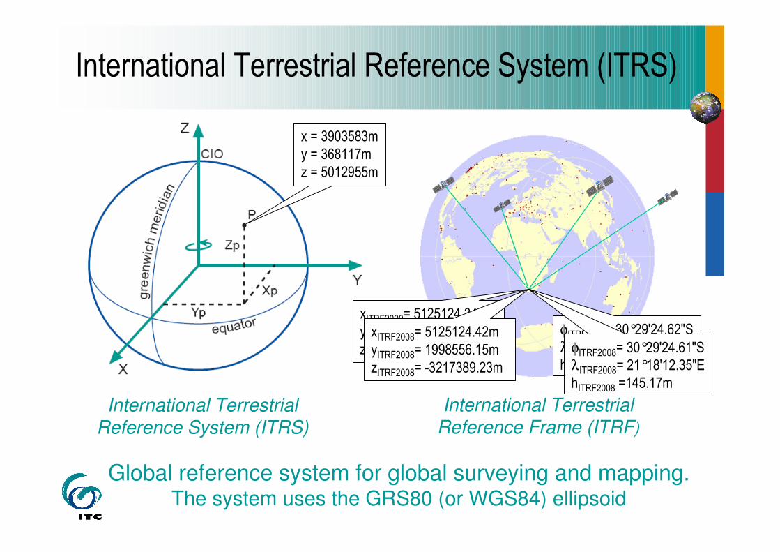
International Terrestrial Reference System (ITRS)
International Terrestrial Reference Frame (ITRF)
International Terrestrial Reference System (ITRS)
Global reference system for global surveying and mapping. The system uses the GRS80 (or WGS84) ellipsoid
x = 3903583m
y = 368117m
z = 5012955m
xITRF2000= 5125124.34m
yITRF2000= 1998556.28m
zITRF2000= -3217389.44m
φITRF2000= 30°29'24.62"SλITRF2000= 21°18'12.36"E
hITRF2000 =145.25m
φITRF2008= 30°29'24.61"SλITRF2008= 21°18'12.35"E
hITRF2008 =145.17m
xITRF2008= 5125124.42m
yITRF2008= 1998556.15m
zITRF2008= -3217389.23m
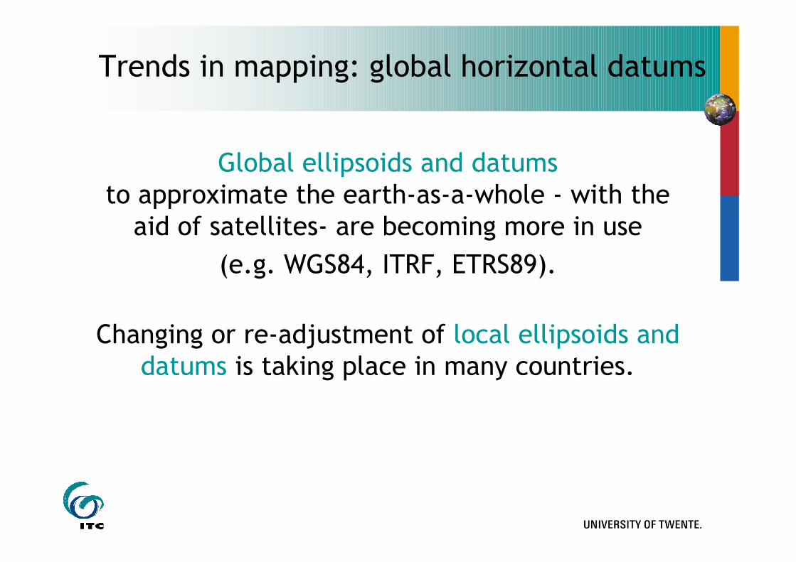
Trends in mapping: global horizontal datums
Global ellipsoids and datumsto approximate the earth-as-a-whole - with the
aid of satellites- are becoming more in use
(e.g. WGS84, ITRF, ETRS89).
Changing or re-adjustment of local ellipsoids and datums is taking place in many countries.
Map projections
26
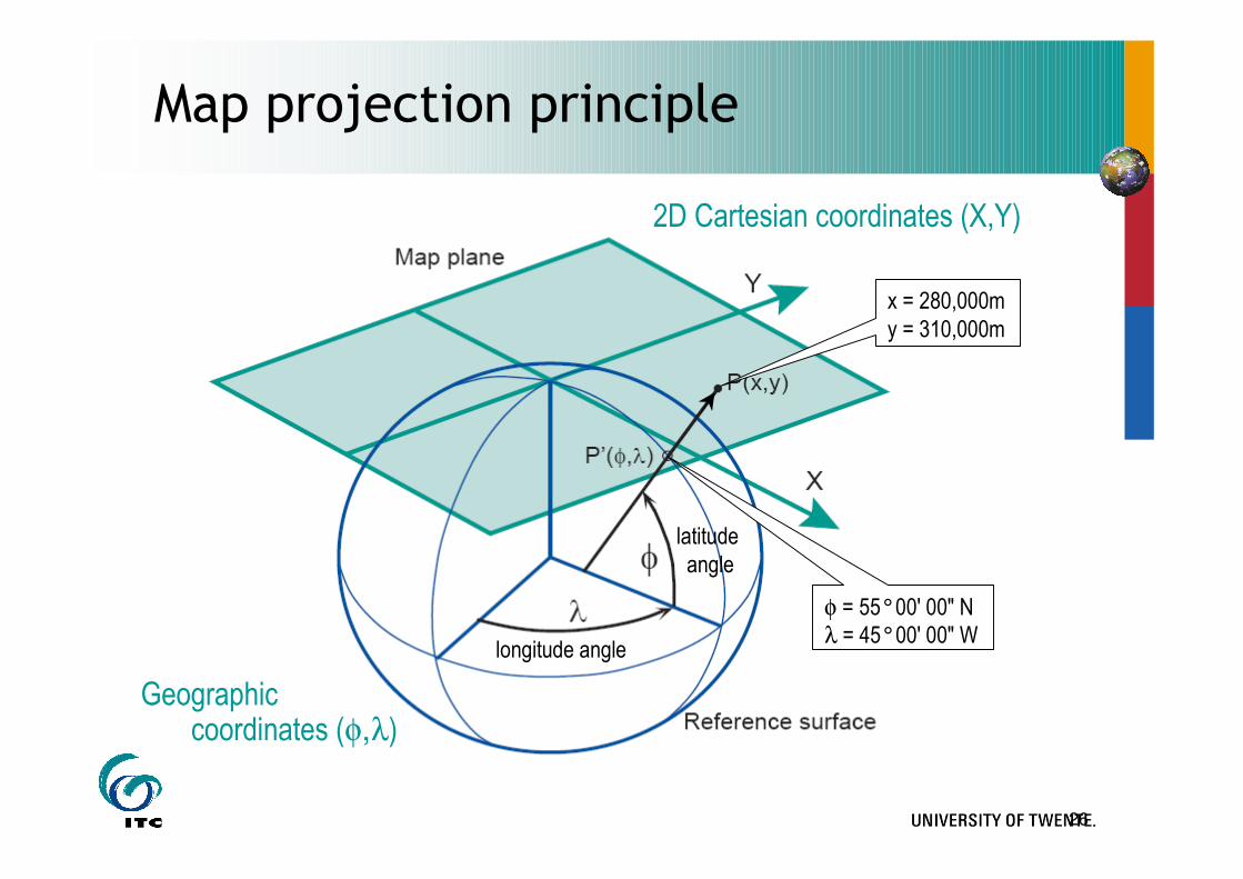
Map projection principle
2D Cartesian coordinates (X,Y)
Geographic coordinates (φ,λ)
longitude angle
latitude
angle
φ = 55°00' 00" N
λ = 45°00' 00" W
x = 280,000m
y = 310,000m
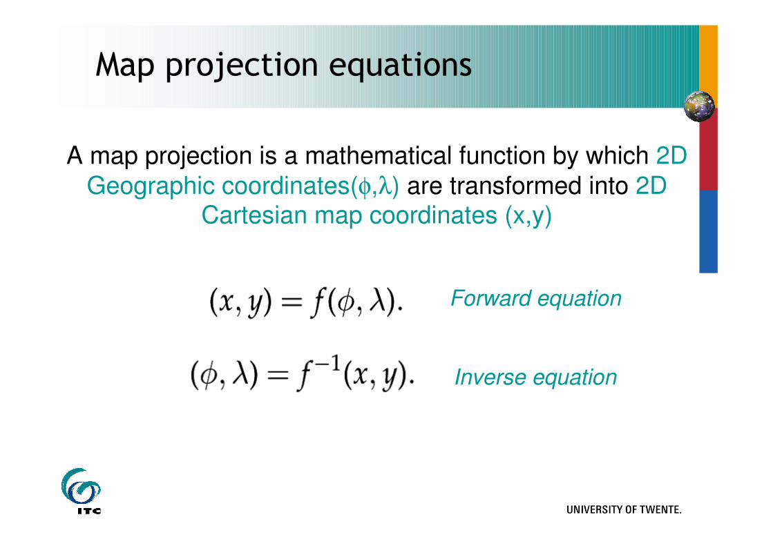
Map projection equations
Forward equation
A map projection is a mathematical function by which 2D
Geographic coordinates(φ,λ) are transformed into 2D Cartesian map coordinates (x,y)
Inverse equation
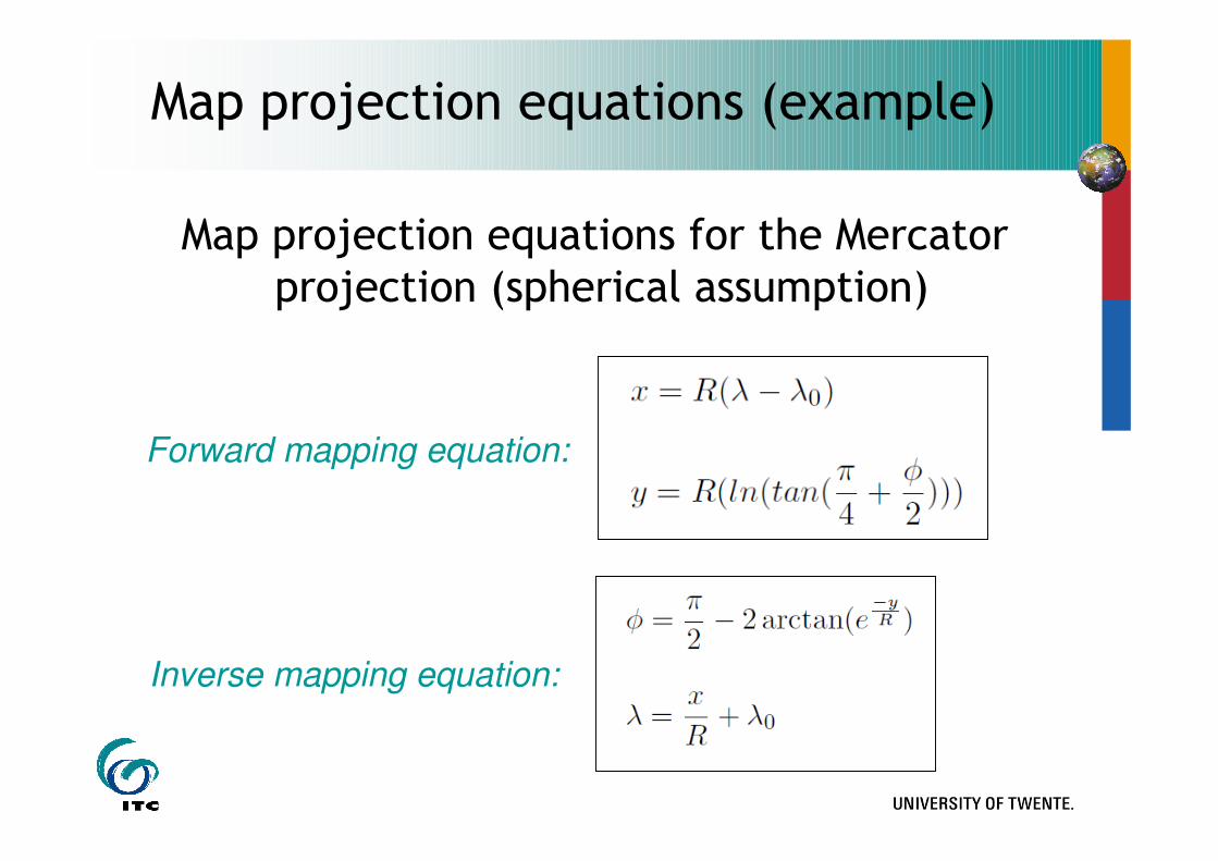
Map projection equations for the Mercator projection (spherical assumption)
Inverse mapping equation:
Forward mapping equation:
Map projection equations (example)
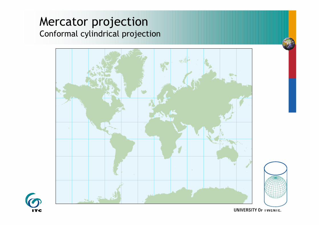
Mercator projectionConformal cylindrical projection
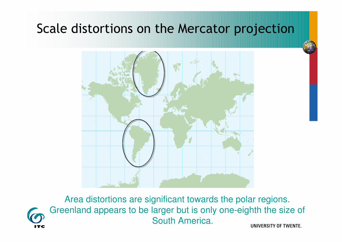
Scale distortions on the Mercator projection
Area distortions are significant towards the polar regions.
Greenland appears to be larger but is only one-eighth the size of
South America.
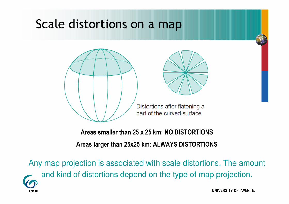
Scale distortions on a map
Areas smaller than 25 x 25 km: NO DISTORTIONS
Areas larger than 25x25 km: ALWAYS DISTORTIONS
Any map projection is associated with scale distortions. The amount
and kind of distortions depend on the type of map projection.
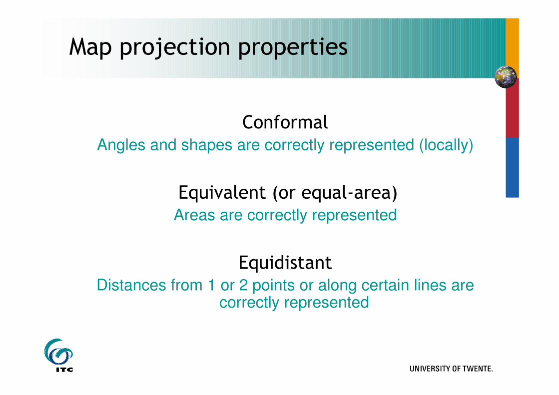
Map projection properties
ConformalAngles and shapes are correctly represented (locally)
Equivalent (or equal-area)Areas are correctly represented
EquidistantDistances from 1 or 2 points or along certain lines are
correctly represented
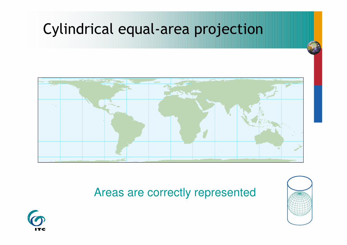
Cylindrical equal-area projection
Areas are correctly represented
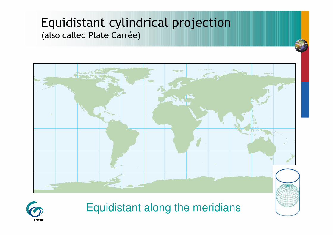
Equidistant cylindrical projection(also called Plate Carrée)
Equidistant along the meridians
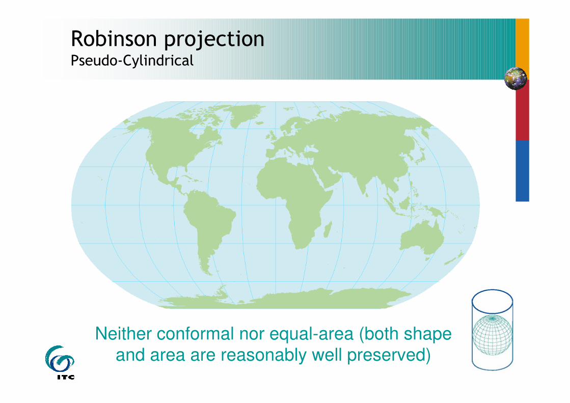
Robinson projectionPseudo-Cylindrical
Neither conformal nor equal-area (both shape and area are reasonably well preserved)
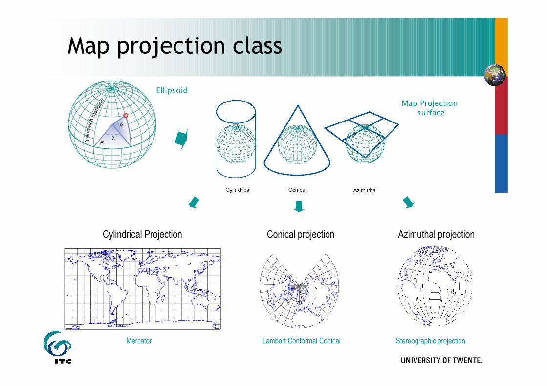
Map projection class
Map Projection surface
Ellipsoid
Cylindrical Projection Conical projection Azimuthal projection
Mercator Lambert Conformal Conical Stereographic projection
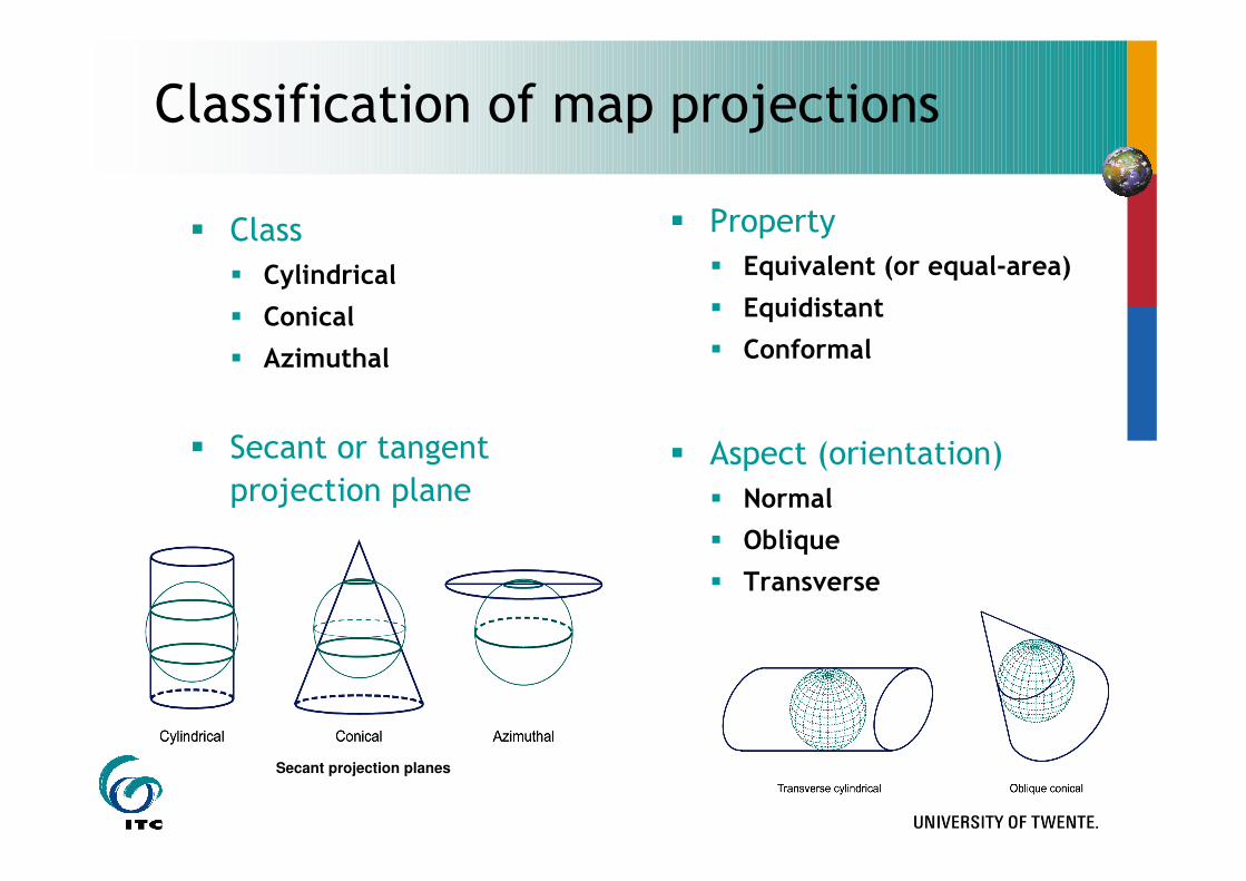
Classification of map projections
� Class
� Cylindrical
� Conical
� Azimuthal
� Secant or tangent
projection plane
� Property
� Equivalent (or equal-area)
� Equidistant
� Conformal
� Aspect (orientation)
� Normal
� Oblique
� Transverse
Secant projection planes
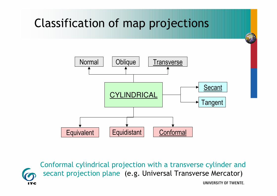
Classification of map projections
CYLINDRICAL
Oblique TransverseNormal
Tangent
Secant
Equidistant ConformalEquivalent
Conformal cylindrical projection with a transverse cylinder and secant projection plane (e.g. Universal Transverse Mercator)

Classification of map projections
CONICAL
Oblique TransverseNormal
Tangent
Secant
Equidistant ConformalEquivalent
Conformal conical projection with a normal cone and tangent projection plane (e.g. Lambert conformal conic)

Classification of map projections
AZIMUTHAL
Oblique TransverseNormal
Tangent
Secant
Equidistant ConformalEquivalent
Conformal azimuthal projection with a tangent polar projection
Plane (e.g. Universal Polar Stereographic)
Polar Equatorial
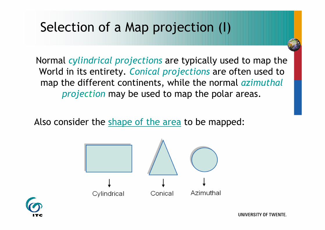
Selection of a Map projection (I)
Normal cylindrical projections are typically used to map theWorld in its entirety. Conical projections are often used tomap the different continents, while the normal azimuthal
projection may be used to map the polar areas.
Also consider the shape of the area to be mapped:
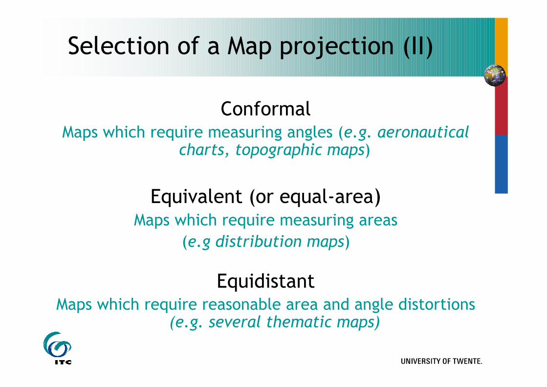
Selection of a Map projection (II)
ConformalMaps which require measuring angles (e.g. aeronautical
charts, topographic maps)
Equivalent (or equal-area)Maps which require measuring areas
(e.g distribution maps)
EquidistantMaps which require reasonable area and angle distortions
(e.g. several thematic maps)
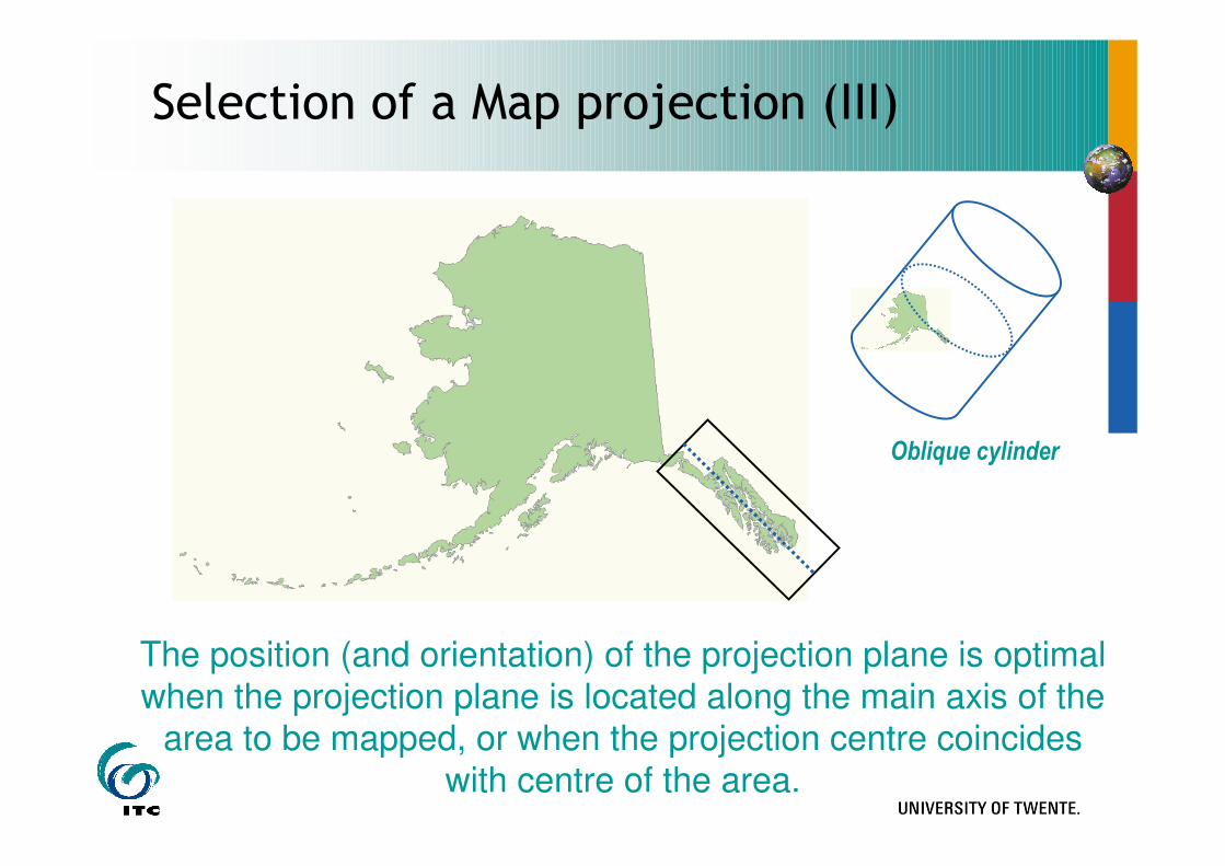
Selection of a Map projection (III)
Oblique cylinder
The position (and orientation) of the projection plane is optimal
when the projection plane is located along the main axis of the area to be mapped, or when the projection centre coincides
with centre of the area.
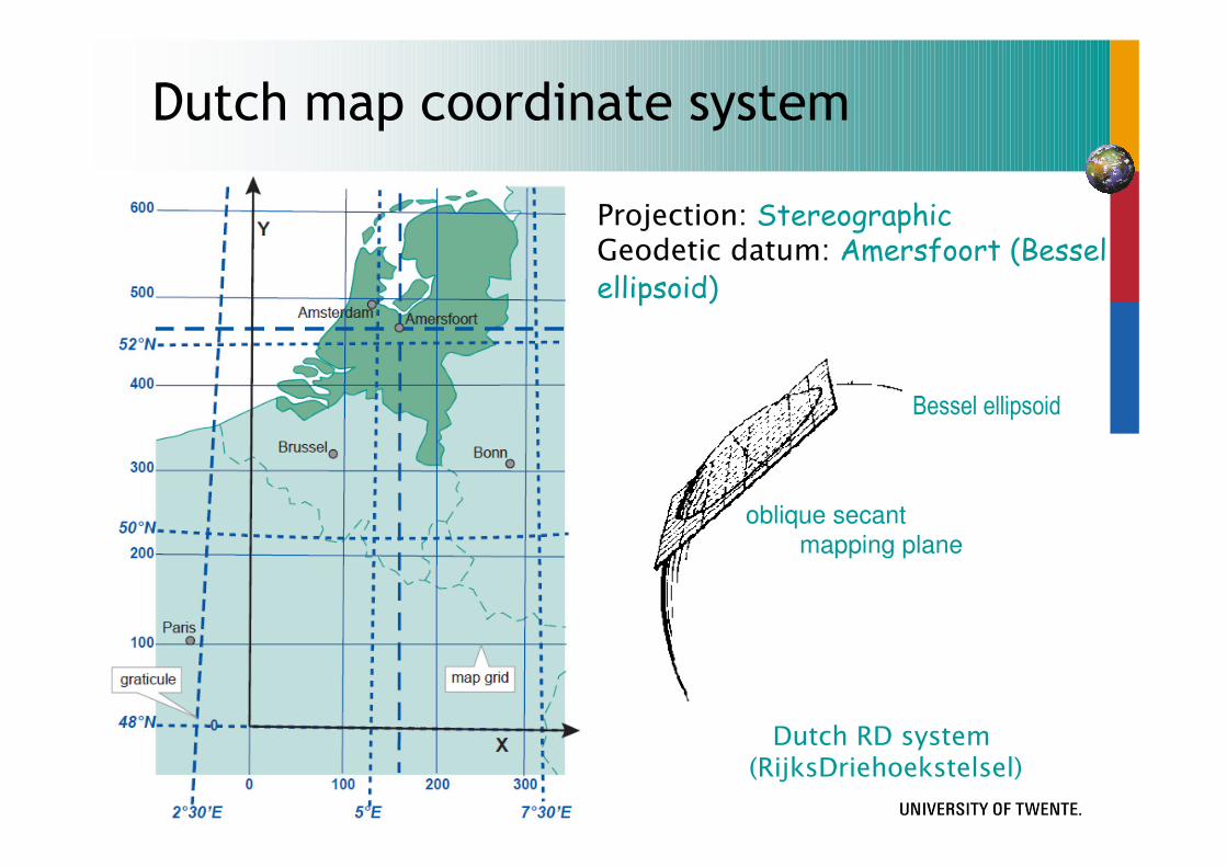
Dutch RD system (RijksDriehoekstelsel)
Dutch map coordinate system
Projection: StereographicGeodetic datum: Amersfoort (Bessel ellipsoid)
Bessel ellipsoid
oblique secant mapping plane

Universal Transverse Mercator
International Standard
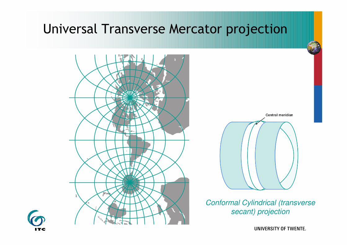
Universal Transverse Mercator projection
Conformal Cylindrical (transverse
secant) projection
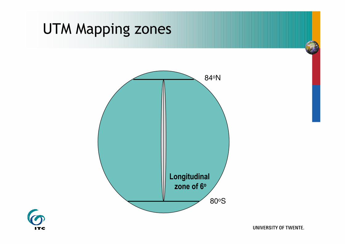
UTM Mapping zones
80oS
84oN
Longitudinal
zone of 6o
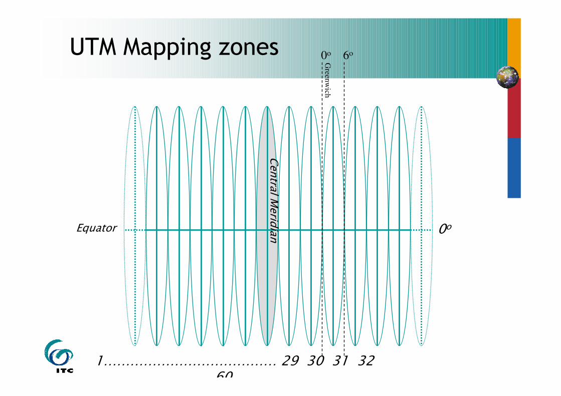
UTM Mapping zones
0oEquator
Central Meridian
Gre
enw
ich
0o 6o
1………………………………… 29 30 31 32 ………………………60
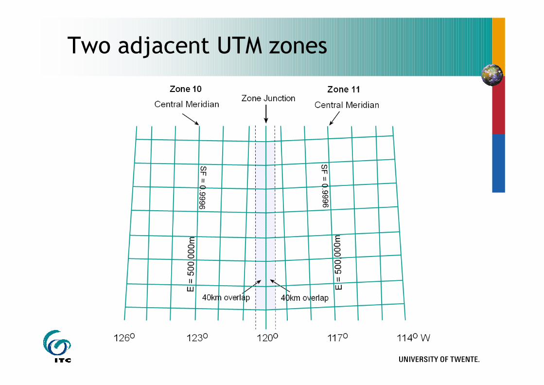
Two adjacent UTM zones
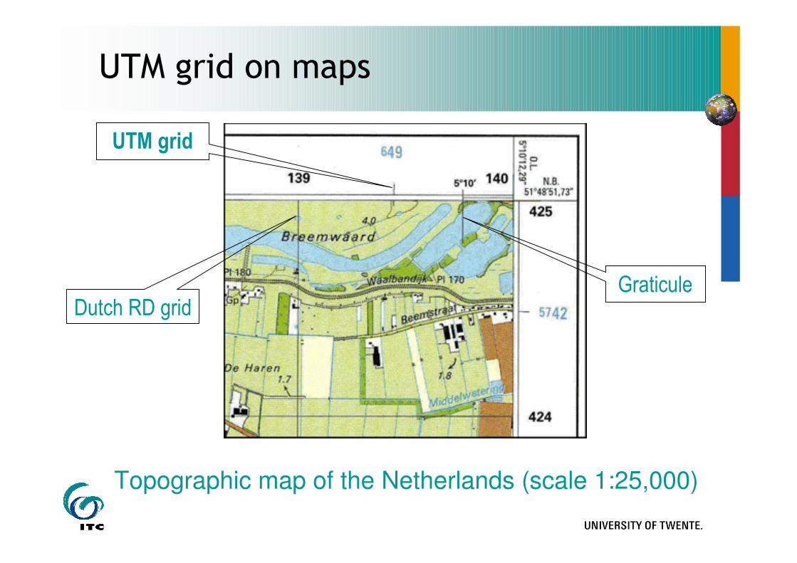
UTM grid on maps
Topographic map of the Netherlands (scale 1:25,000)
GraticuleDutch RD grid
UTM grid
Coordinate transformations
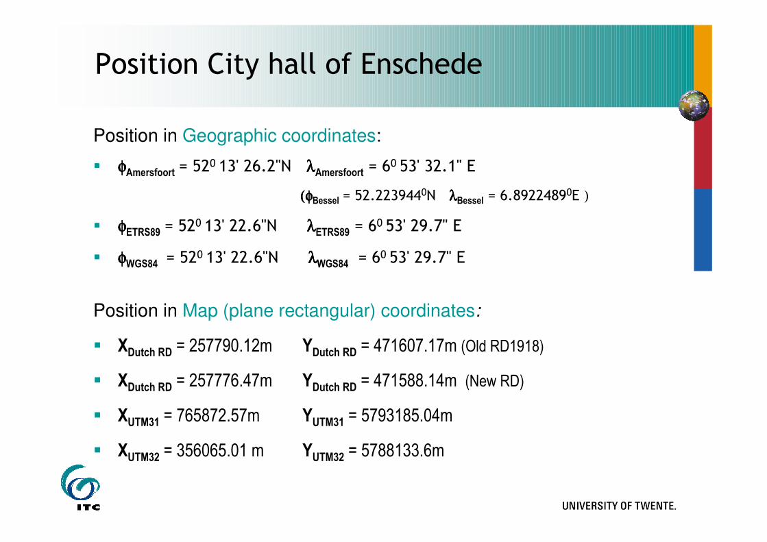
Position City hall of Enschede
Position in Geographic coordinates:
� φφφφAmersfoort = 520 13' 26.2"N λλλλAmersfoort = 6
0 53' 32.1" E
(φ(φ(φ(φBessel = 52.2239440N λλλλBessel = 6.8922489
0E )
� φφφφETRS89 = 520 13' 22.6"N λλλλETRS89 = 60 53' 29.7" E
� φφφφWGS84 = 520 13' 22.6"N λλλλWGS84 = 60 53' 29.7" E
Position in Map (plane rectangular) coordinates:
� XDutch RD = 257790.12m YDutch RD = 471607.17m (Old RD1918)
� XDutch RD = 257776.47m YDutch RD = 471588.14m (New RD)
� XUTM31 = 765872.57m YUTM31 = 5793185.04m
� XUTM32 = 356065.01 m YUTM32 = 5788133.6m
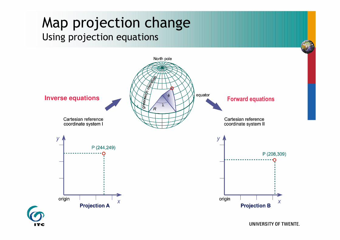
Map projection changeUsing projection equations
Inverse equations Forward equations
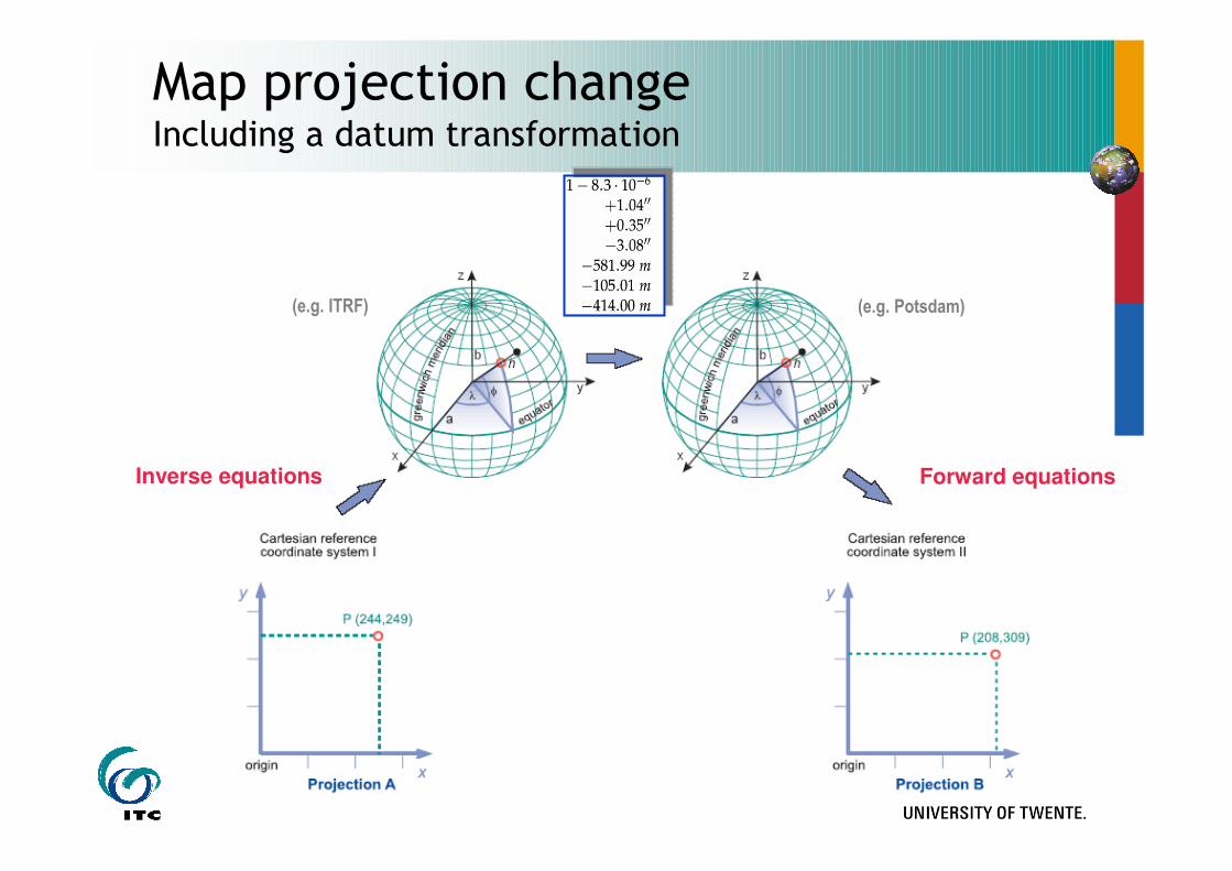
Map projection changeIncluding a datum transformation
(e.g. ITRF) (e.g. Potsdam)
Inverse equations Forward equations
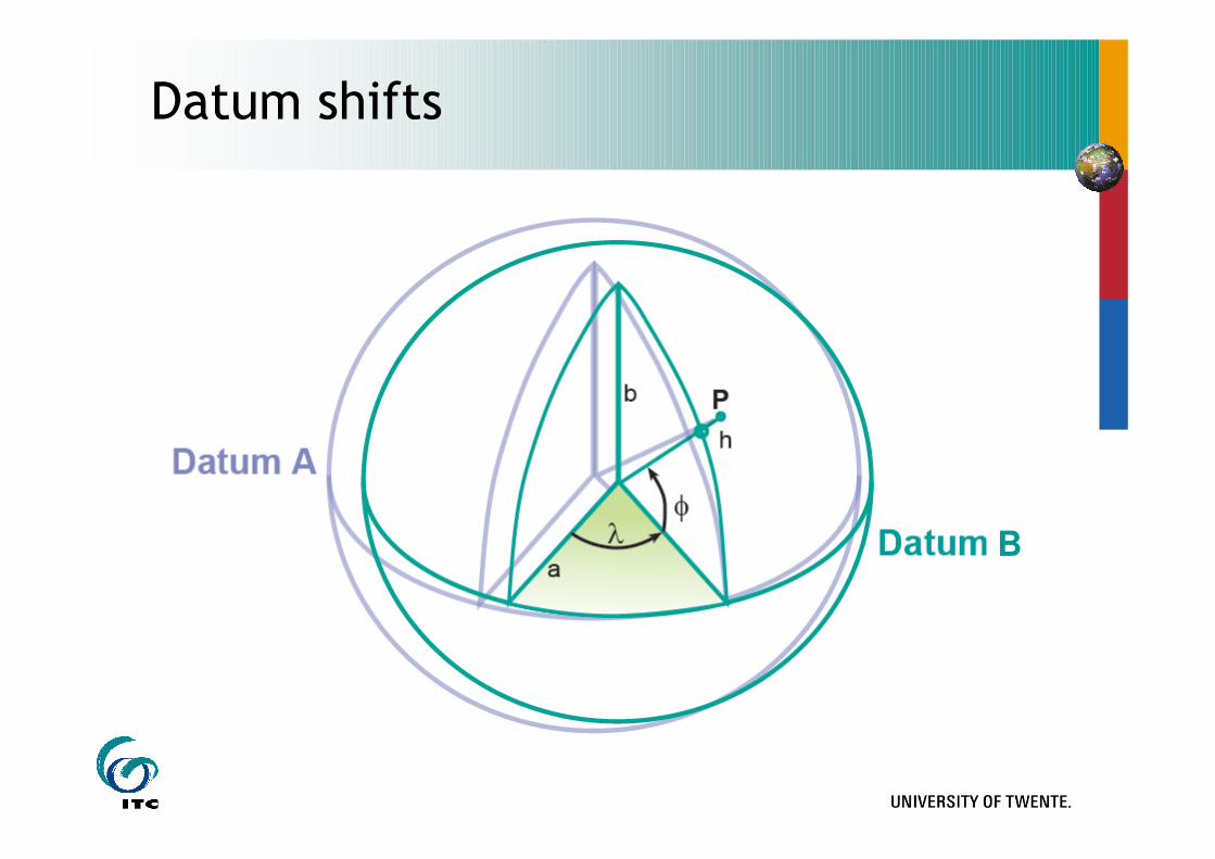
Datum shifts
B
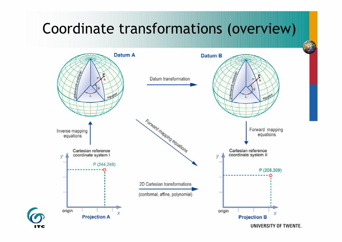
Coordinate transformations (overview)
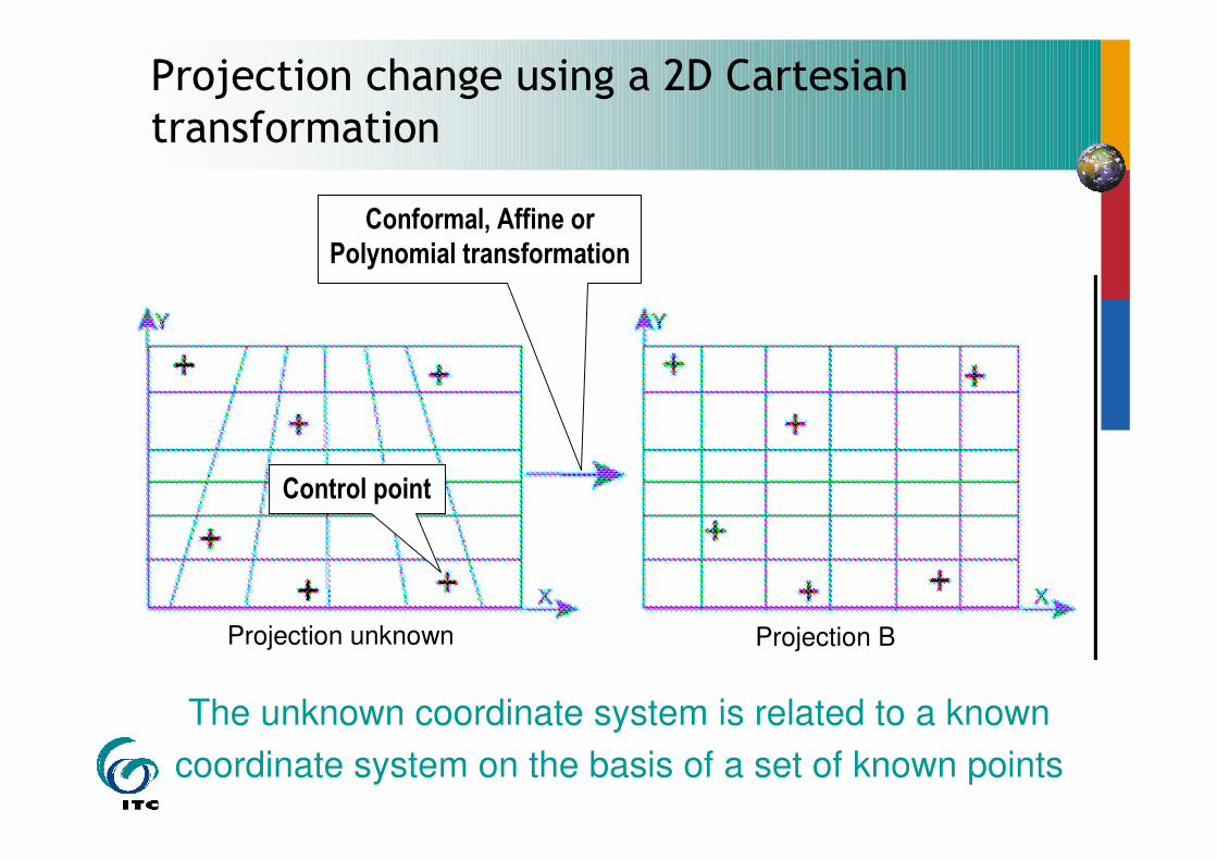
Projection unknown
Conformal, Affine or
Polynomial transformation
Projection change using a 2D Cartesian transformation
Control point
Projection B
The unknown coordinate system is related to a known
coordinate system on the basis of a set of known points
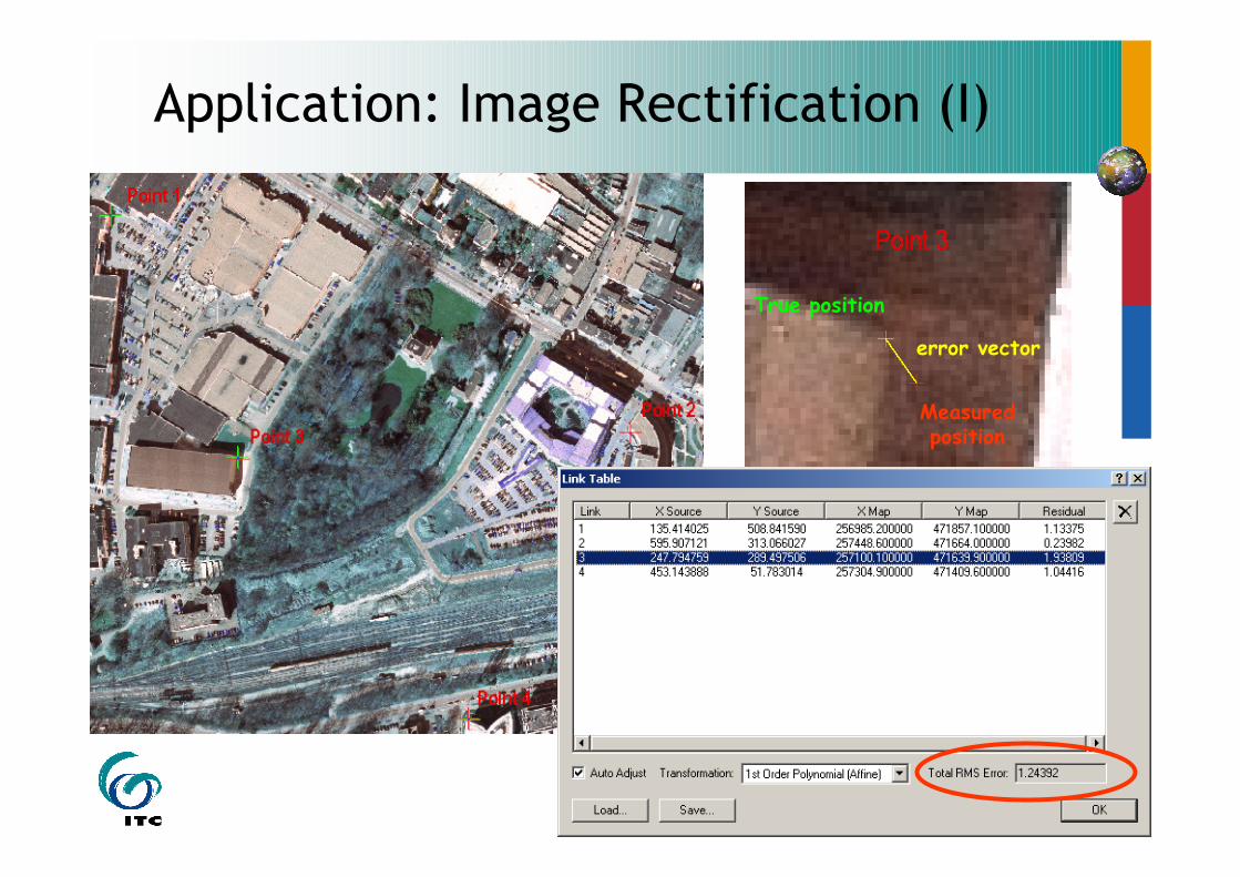
Application: Image Rectification (I)
True position
Measured position
error vector
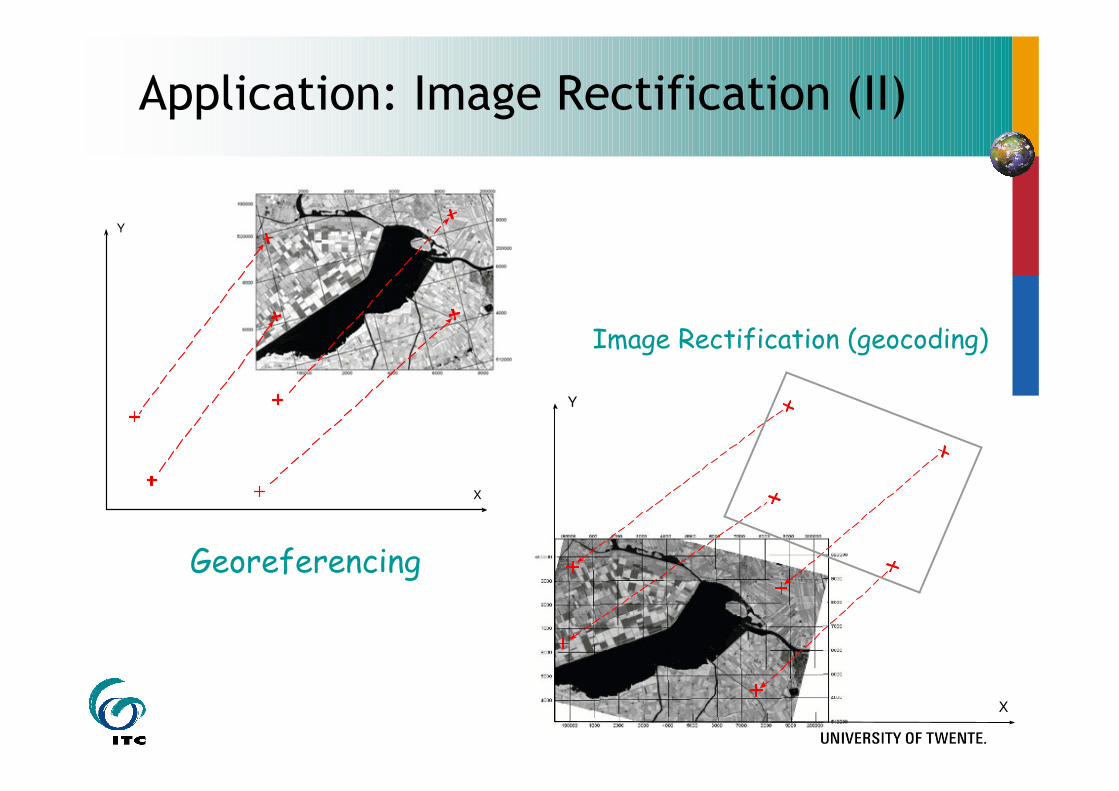
Application: Image Rectification (II)
Georeferencing
Image Rectification (geocoding)
X
Y
X
Y
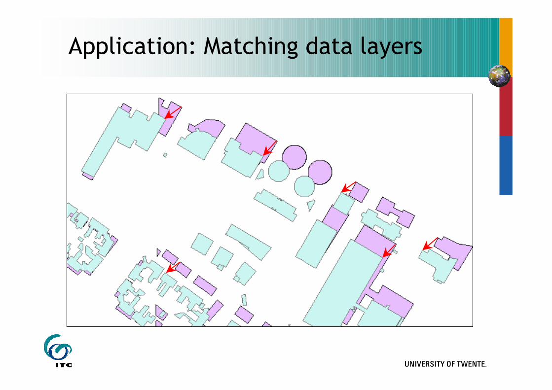
Application: Matching data layers
INTERNATIONAL INSTITUTE FOR GEO-INFORMATION SCIENCE AND EARTH OBSERVATION
Thank you!