Neutrino Factory R&D - Welcome to the University of Warwick · PDF file ·...
42
1 Neutrino Factory R&D John Back University of Warwick 1 st March 2007
Transcript of Neutrino Factory R&D - Welcome to the University of Warwick · PDF file ·...
1
Neutrino Factory R&D
John BackUniversity of Warwick
1st March 2007
Outline
• Why do we need a Neutrino Factory?• A sample of UK R&D work
– Front End Test Stand @ RAL– Target Studies– Other work
• Summary
01/03/07 Seminar 2
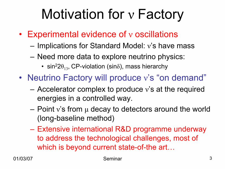
Motivation for ν Factory• Experimental evidence of ν oscillations
– Implications for Standard Model: ν’s have mass– Need more data to explore neutrino physics:
• sin22θ13, CP-violation (sinδ), mass hierarchy
• Neutrino Factory will produce ν’s “on demand”– Accelerator complex to produce ν’s at the required
energies in a controlled way. – Point ν’s from µ decay to detectors around the world
(long-baseline method)– Extensive international R&D programme underway
to address the technological challenges, most of which is beyond current state-of-the art…
01/03/07 Seminar 3
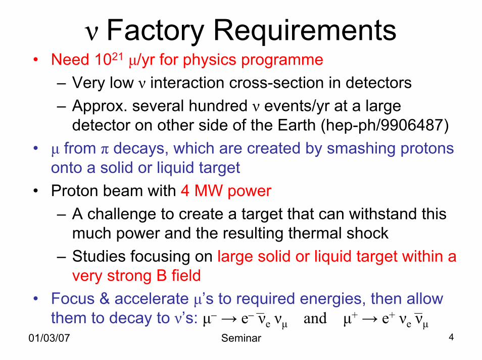
ν Factory Requirements• Need 1021 µ/yr for physics programme
– Very low ν interaction cross-section in detectors– Approx. several hundred ν events/yr at a large
detector on other side of the Earth (hep-ph/9906487)• µ from π decays, which are created by smashing protons
onto a solid or liquid target• Proton beam with 4 MW power
– A challenge to create a target that can withstand this much power and the resulting thermal shock
– Studies focusing on large solid or liquid target within a very strong B field
• Focus & accelerate µ’s to required energies, then allow them to decay to ν’s: µ− → e− νe νµ and µ+ → e+ νe νµ
01/03/07 Seminar 4
01/03/07 Seminar 5
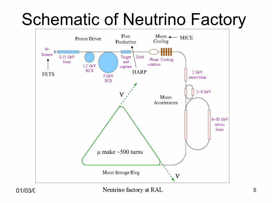
Schematic of Neutrino Factory
ν
ν
MICE
FETS HARP
µ make ~500 turns
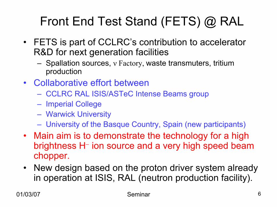
Front End Test Stand (FETS) @ RAL• FETS is part of CCLRC’s contribution to accelerator
R&D for next generation facilities– Spallation sources, ν Factory, waste transmuters, tritium
production• Collaborative effort between
– CCLRC RAL ISIS/ASTeC Intense Beams group– Imperial College– Warwick University– University of the Basque Country, Spain (new participants)
• Main aim is to demonstrate the technology for a high brightness H− ion source and a very high speed beam chopper.
• New design based on the proton driver system already in operation at ISIS, RAL (neutron production facility).
01/03/07 Seminar 6
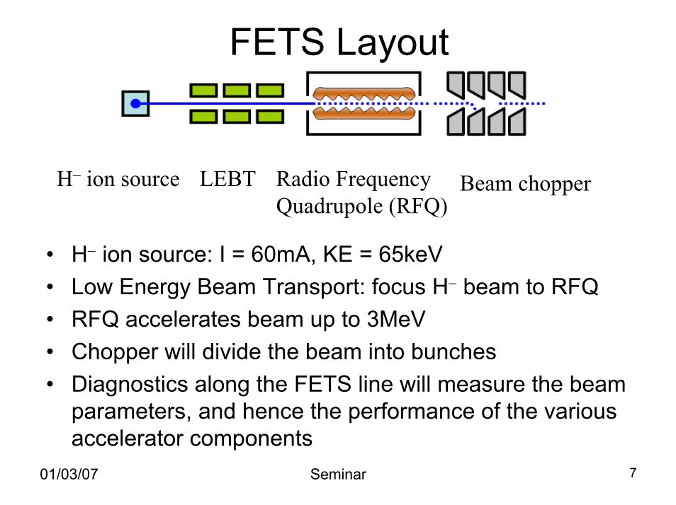
FETS Layout
H– ion source LEBT Radio Frequency Quadrupole (RFQ)
Beam chopper
• H− ion source: I = 60mA, KE = 65keV• Low Energy Beam Transport: focus H− beam to RFQ• RFQ accelerates beam up to 3MeV• Chopper will divide the beam into bunches• Diagnostics along the FETS line will measure the beam
parameters, and hence the performance of the various accelerator components
01/03/07 Seminar 7
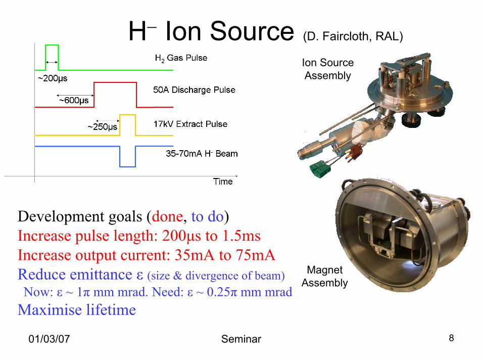
H− Ion Source (D. Faircloth, RAL)
Ion SourceAssembly
MagnetAssembly
Development goals (done, to do)Increase pulse length: 200µs to 1.5msIncrease output current: 35mA to 75mAReduce emittance ε (size & divergence of beam)Now: ε ~ 1π mm mrad. Need: ε ~ 0.25π mm mrad
Maximise lifetime
01/03/07 Seminar 8
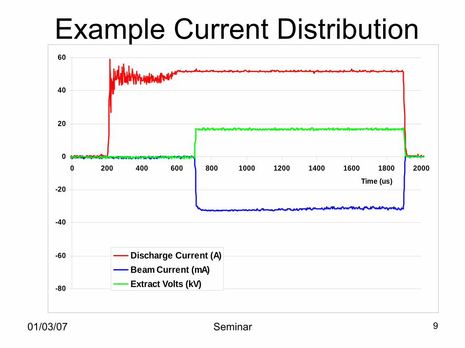
-80
-60
-40
-20
0
20
40
60
0 200 400 600 800 1000 1200 1400 1600 1800 2000
Time (us)
Discharge Current (A)Beam Current (mA)Extract Volts (kV)
Example Current Distribution
01/03/07 Seminar 9
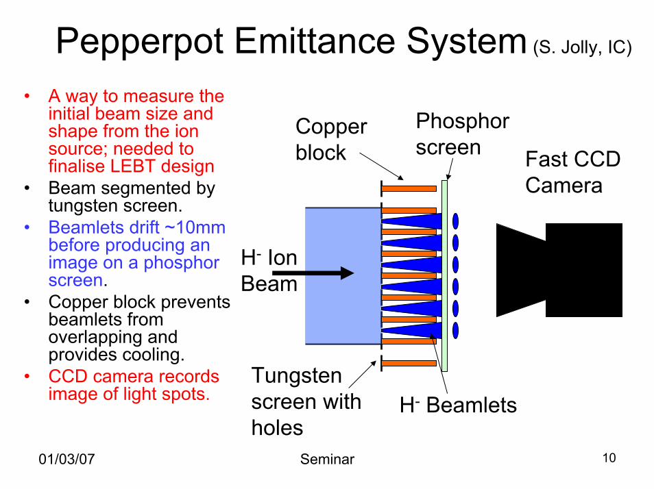
Pepperpot Emittance System (S. Jolly, IC)
H- Ion Beam
Tungsten screen with holes
Copper block
Phosphor screen
H- Beamlets
Fast CCD Camera
• A way to measure the initial beam size and shape from the ion source; needed to finalise LEBT design
• Beam segmented by tungsten screen.
• Beamlets drift ~10mm before producing an image on a phosphor screen.
• Copper block prevents beamlets from overlapping and provides cooling.
• CCD camera records image of light spots.
01/03/07 Seminar 10
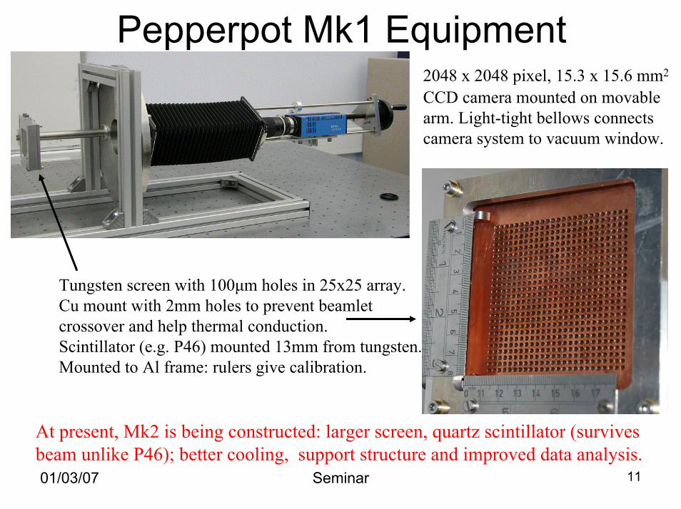
Pepperpot Mk1 Equipment
Tungsten screen with 100µm holes in 25x25 array.Cu mount with 2mm holes to prevent beamletcrossover and help thermal conduction.Scintillator (e.g. P46) mounted 13mm from tungsten.Mounted to Al frame: rulers give calibration.
2048 x 2048 pixel, 15.3 x 15.6 mm2
CCD camera mounted on movable arm. Light-tight bellows connects camera system to vacuum window.
At present, Mk2 is being constructed: larger screen, quartz scintillator (survivesbeam unlike P46); better cooling, support structure and improved data analysis.01/03/07 Seminar 11
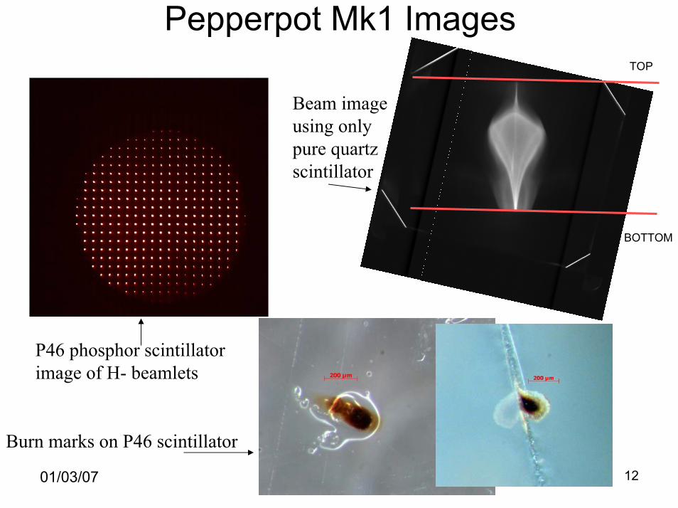
Pepperpot Mk1 Images
01/03/07 Seminar 12
P46 phosphor scintillatorimage of H- beamlets
Burn marks on P46 scintillator
Beam image using only pure quartz scintillator
TOP
BOTTOM
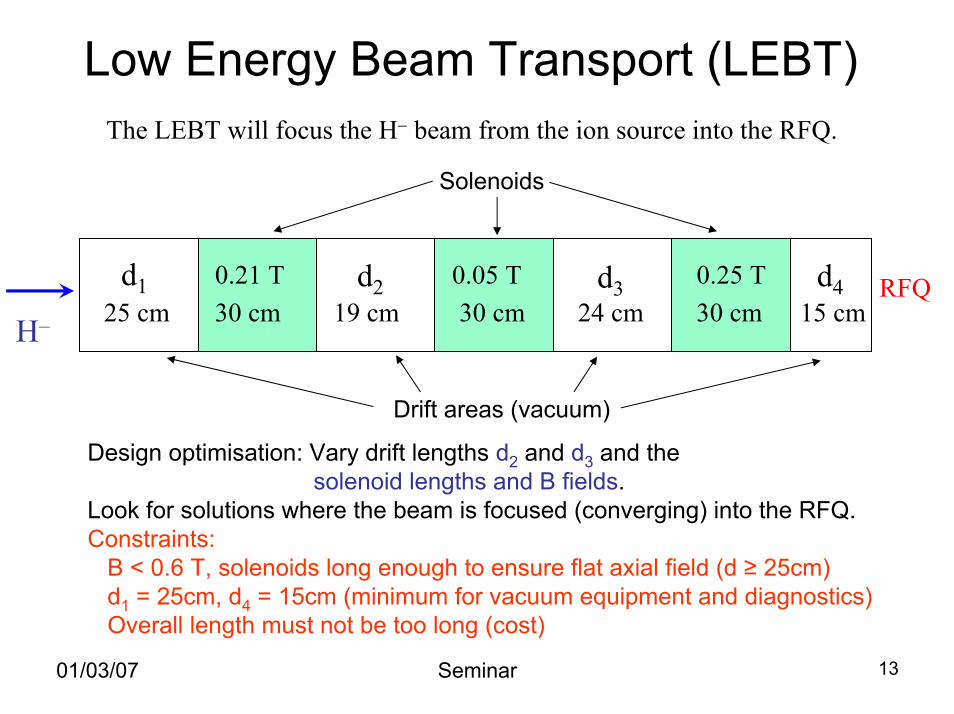
Low Energy Beam Transport (LEBT)The LEBT will focus the H− beam from the ion source into the RFQ.
25 cm 30 cm 19 cm 30 cm 24 cm 30 cm 15 cm0.21 T 0.05 T 0.25 Td1 d2 d3 d4
H–
RFQ
Solenoids
Drift areas (vacuum)
Design optimisation: Vary drift lengths d2 and d3 and the solenoid lengths and B fields.
Look for solutions where the beam is focused (converging) into the RFQ.Constraints:
B < 0.6 T, solenoids long enough to ensure flat axial field (d ≥ 25cm)d1 = 25cm, d4 = 15cm (minimum for vacuum equipment and diagnostics)Overall length must not be too long (cost)
01/03/07 Seminar 13
01/03/07 Seminar 14
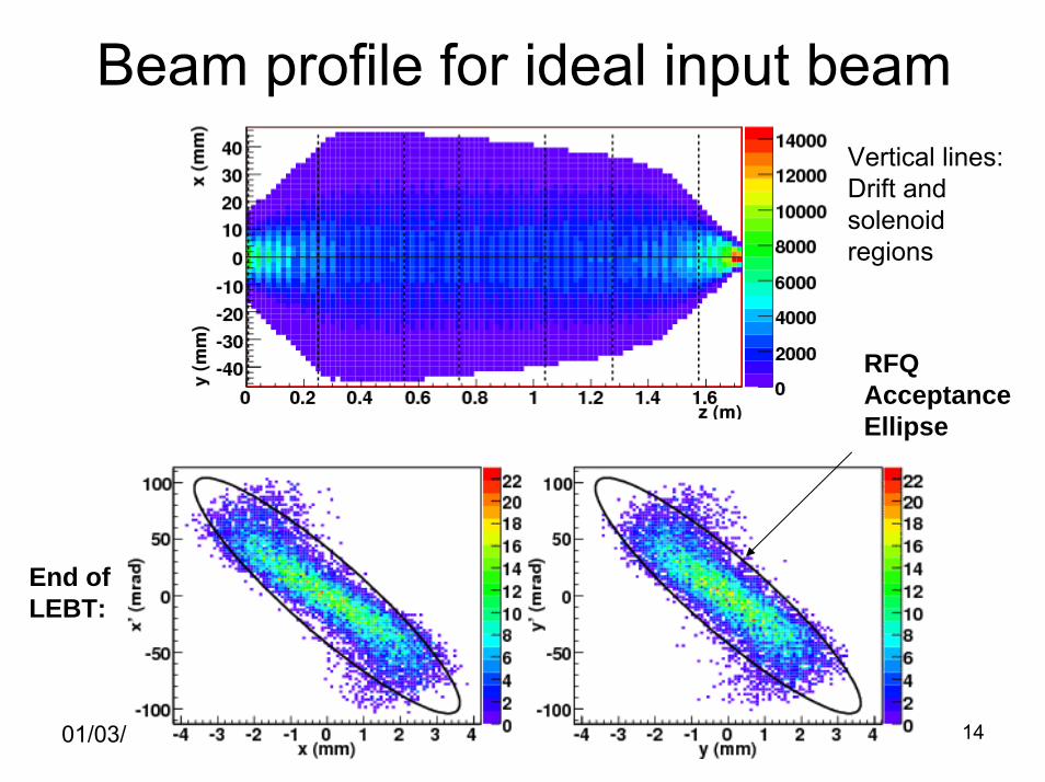
Beam profile for ideal input beam
RFQAcceptanceEllipse
Vertical lines:Drift and solenoidregions
End ofLEBT:
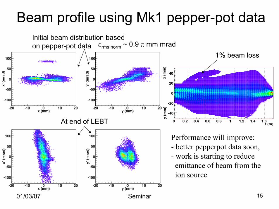
Beam profile using Mk1 pepper-pot dataInitial beam distribution based on pepper-pot data
At end of LEBT
εrms norm ~ 0.9 π mm mrad1% beam loss
Performance will improve:- better pepperpot data soon,- work is starting to reduceemittance of beam from theion source
01/03/07 Seminar 15
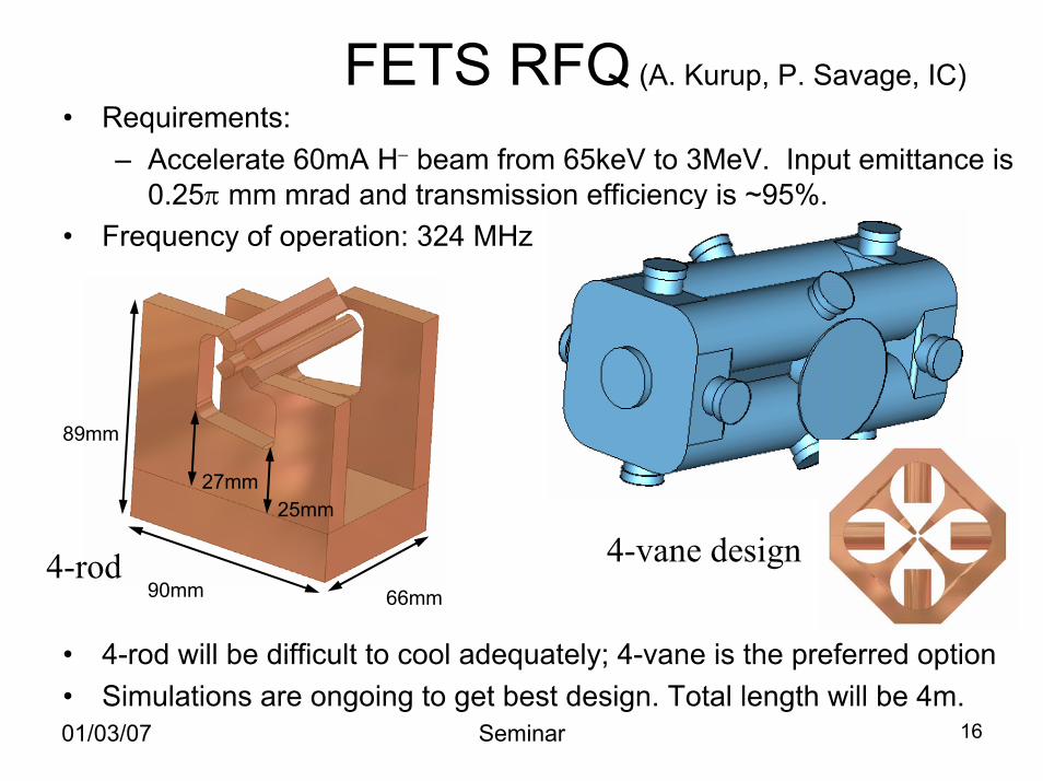
FETS RFQ (A. Kurup, P. Savage, IC)• Requirements:
– Accelerate 60mA H− beam from 65keV to 3MeV. Input emittance is 0.25π mm mrad and transmission efficiency is ~95%.
• Frequency of operation: 324 MHz
• 4-rod will be difficult to cool adequately; 4-vane is the preferred option• Simulations are ongoing to get best design. Total length will be 4m.
89mm
90mm 66mm
27mm25mm
4-rod 4-vane design
01/03/07 Seminar 16
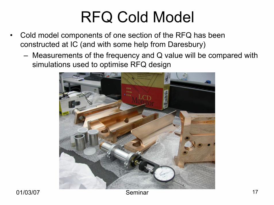
RFQ Cold Model• Cold model components of one section of the RFQ has been
constructed at IC (and with some help from Daresbury)– Measurements of the frequency and Q value will be compared with
simulations used to optimise RFQ design
01/03/07 Seminar 17
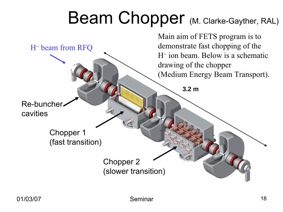
Beam Chopper (M. Clarke-Gayther, RAL)
Chopper 1 (fast transition)
Chopper 2 (slower transition)
Re-bunchercavities
3.2 m
Main aim of FETS program is to demonstrate fast chopping of the H− ion beam. Below is a schematic drawing of the chopper(Medium Energy Beam Transport).
H− beam from RFQ
01/03/07 Seminar 18
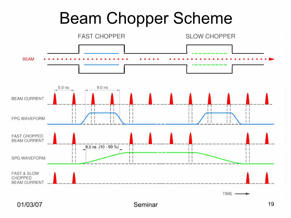
Beam Chopper Scheme
01/03/07 Seminar 19
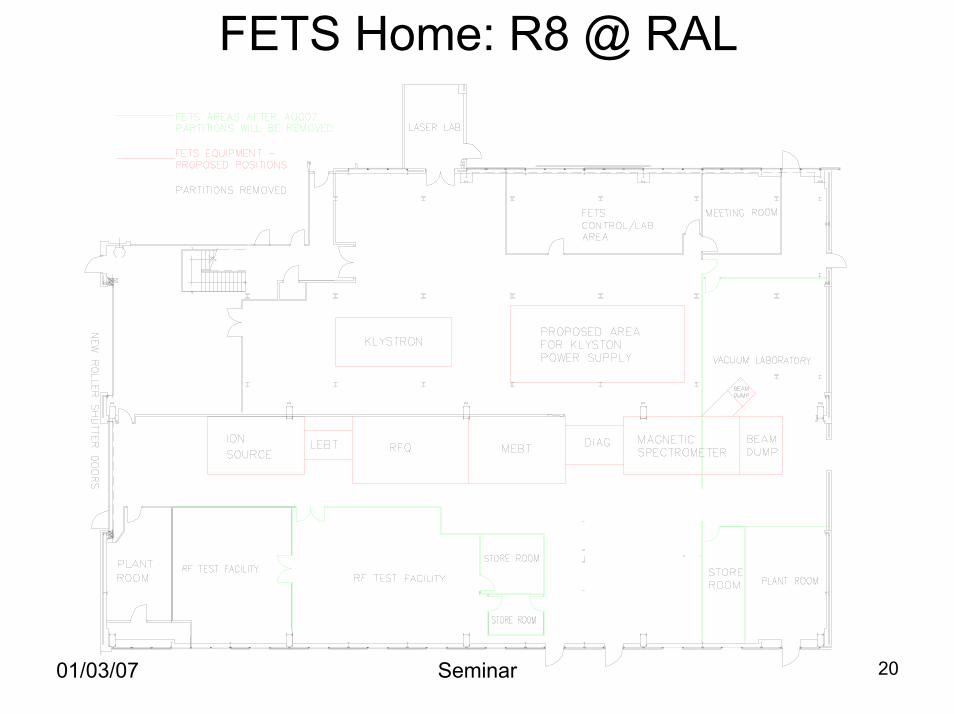
FETS Home: R8 @ RAL
01/03/07 Seminar 20
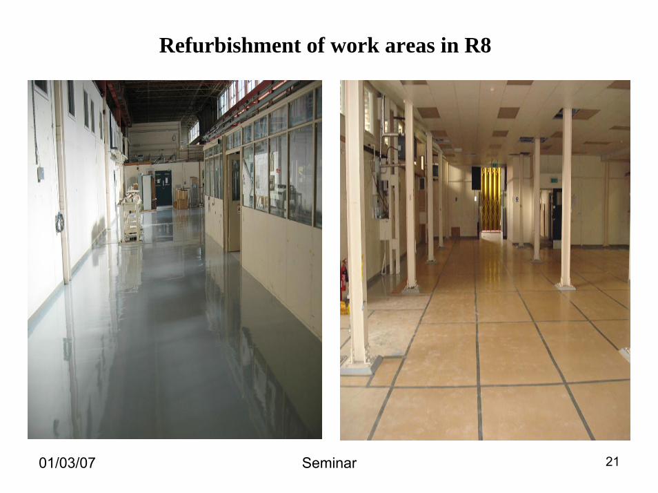
Refurbishment of work areas in R8
01/03/07 Seminar 21
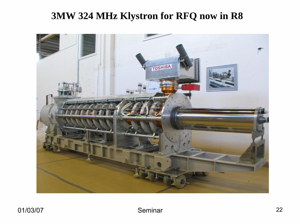
3MW 324 MHz Klystron for RFQ now in R8
01/03/07 Seminar 22
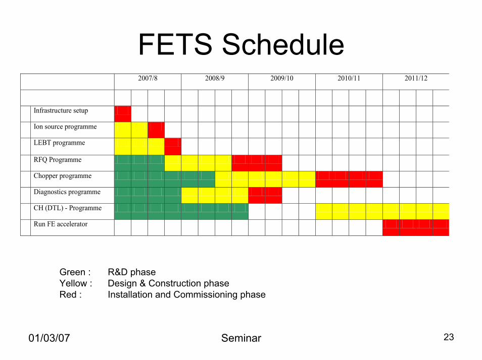
FETS Schedule 2007/8 2008/9 2009/10 2010/11 2011/12
Infrastructure setup
Ion source programme
LEBT programme
RFQ Programme
Chopper programme
Diagnostics programme
CH (DTL) - Programme
Run FE accelerator
Green : R&D phaseYellow : Design & Construction phaseRed : Installation and Commissioning phase
01/03/07 Seminar 23
Target Studies• Create π (→µ → ν) by bombarding target with protons. • Proton beam power of 4 MW required to get 1021 µ/yr.
– Solid targets can generally only cope with ~1.5 MW before breaking/melting…
• Extreme heating, shock and radiation damage suggest:– Moving, large, solid target with extensive cooling– A liquid metal (Hg) jet target
• UK studies focusing on solid targets (RAL,Sheffield,Warwick)– Investigating best material (i.e. survives beam)– Optimising target geometry
• Size/shape/arrangement of solid target (maximise π yield)• Amount of cooling and shielding required• Solenoid configuration to get 20T field to focus π and µ
01/03/07 Seminar 24
01/03/07 Seminar 25
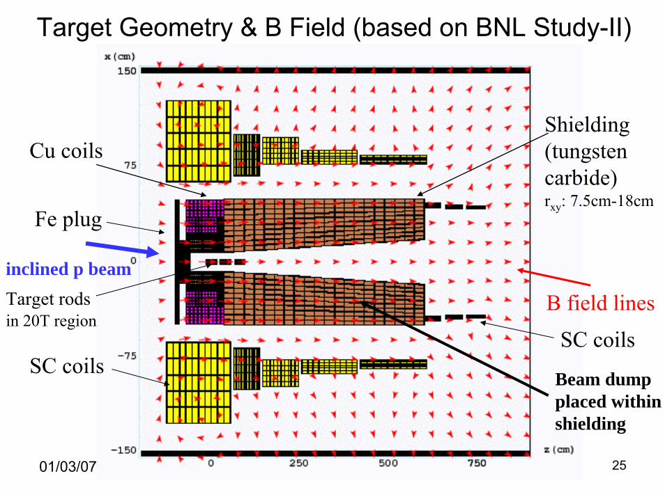
Target Geometry & B Field (based on BNL Study-II)
B field linesTarget rodsin 20T region
SC coils
Cu coilsShielding(tungstencarbide)rxy: 7.5cm-18cm
Fe plug
SC coils
inclined p beam
Beam dumpplaced within shielding
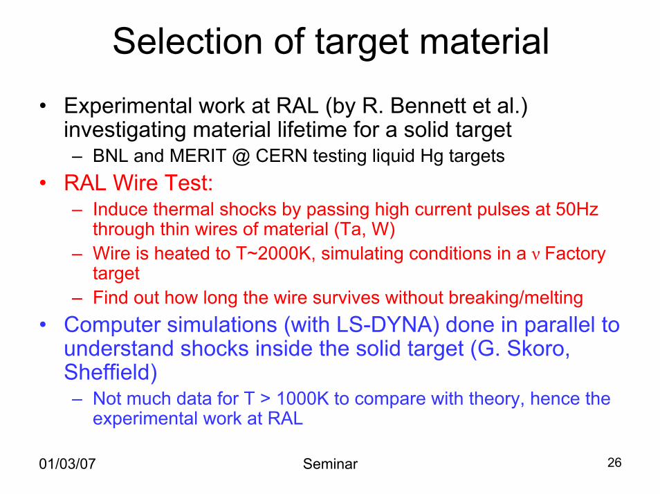
Selection of target material• Experimental work at RAL (by R. Bennett et al.)
investigating material lifetime for a solid target– BNL and MERIT @ CERN testing liquid Hg targets
• RAL Wire Test:– Induce thermal shocks by passing high current pulses at 50Hz
through thin wires of material (Ta, W)– Wire is heated to T~2000K, simulating conditions in a ν Factory
target– Find out how long the wire survives without breaking/melting
• Computer simulations (with LS-DYNA) done in parallel to understand shocks inside the solid target (G. Skoro, Sheffield)– Not much data for T > 1000K to compare with theory, hence the
experimental work at RAL
01/03/07 Seminar 26
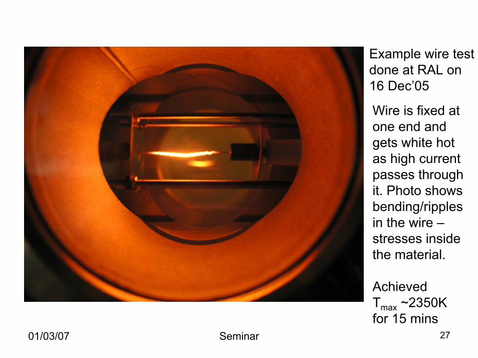
Example wire testdone at RAL on 16 Dec’05
Wire is fixed at one end and gets white hot as high current passes through it. Photo shows bending/ripples in the wire –stresses inside the material.
Achieved Tmax ~2350K for 15 mins
01/03/07 Seminar 27
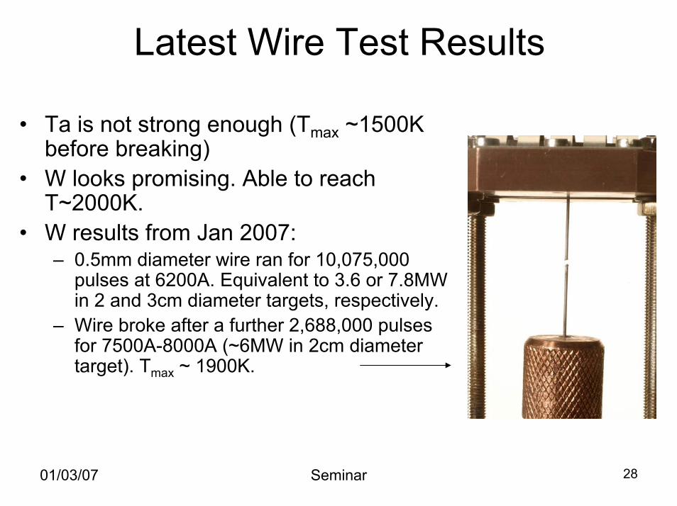
Latest Wire Test Results
• Ta is not strong enough (Tmax ~1500K before breaking)
• W looks promising. Able to reach T~2000K.
• W results from Jan 2007:– 0.5mm diameter wire ran for 10,075,000
pulses at 6200A. Equivalent to 3.6 or 7.8MW in 2 and 3cm diameter targets, respectively.
– Wire broke after a further 2,688,000 pulses for 7500A-8000A (~6MW in 2cm diameter target). Tmax ~ 1900K.
01/03/07 Seminar 28
01/03/07 Seminar 29
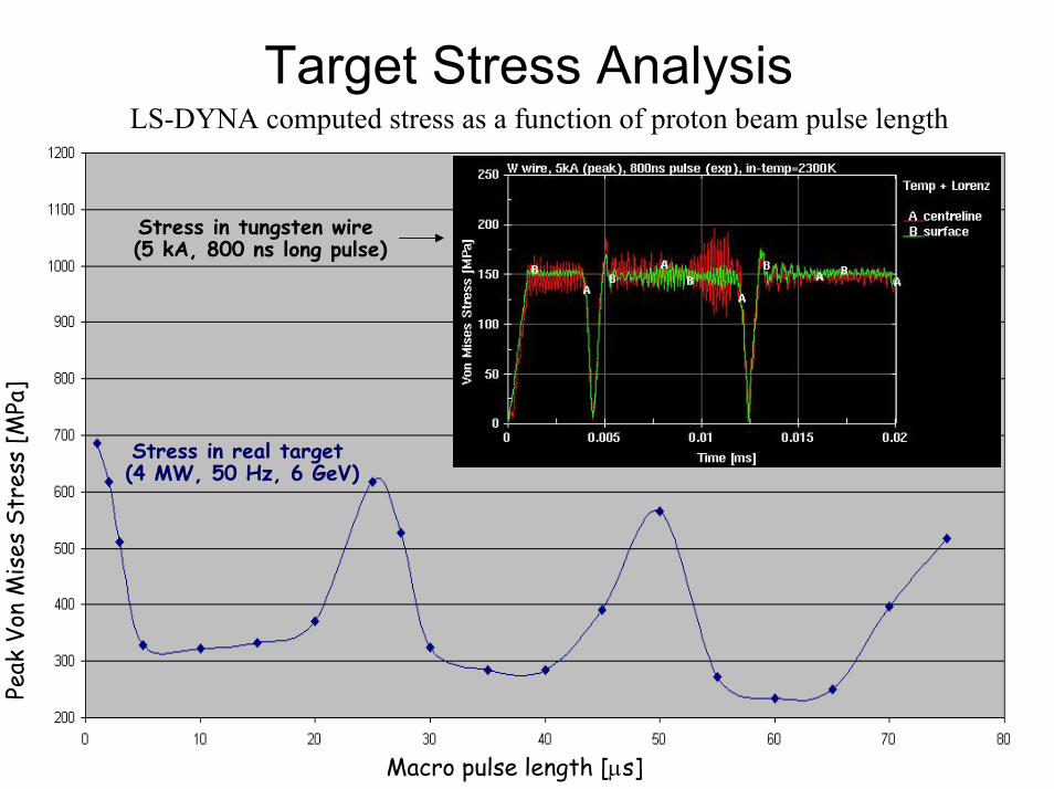
Stress in real target (4 MW, 50 Hz, 6 GeV)
Macro pulse length [µs]
Peak
Von
Mis
es S
tres
s [M
Pa]
Stress in tungsten wire (5 kA, 800 ns long pulse)
Target Stress AnalysisLS-DYNA computed stress as a function of proton beam pulse length
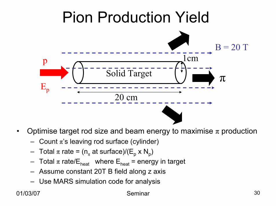
Pion Production Yield
• Optimise target rod size and beam energy to maximise π production– Count π’s leaving rod surface (cylinder)– Total π rate = (nπ at surface)/(Ep x Np)– Total π rate/Eheat where Eheat = energy in target– Assume constant 20T B field along z axis– Use MARS simulation code for analysis
20 cm
B = 20 Tp
Solid Target
1cm
Ep
π
01/03/07 Seminar 30
01/03/07 Seminar 31
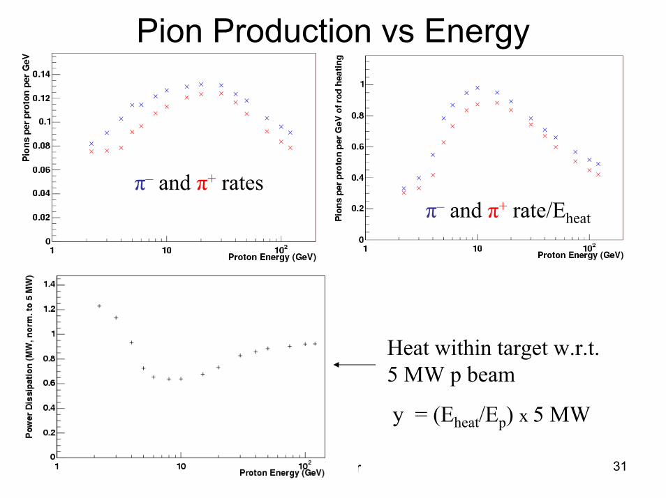
Pion Production vs Energy
Heat within target w.r.t. 5 MW p beam
y = (Eheat/Ep) x 5 MW
π– and π+ ratesπ– and π+ rate/Eheat
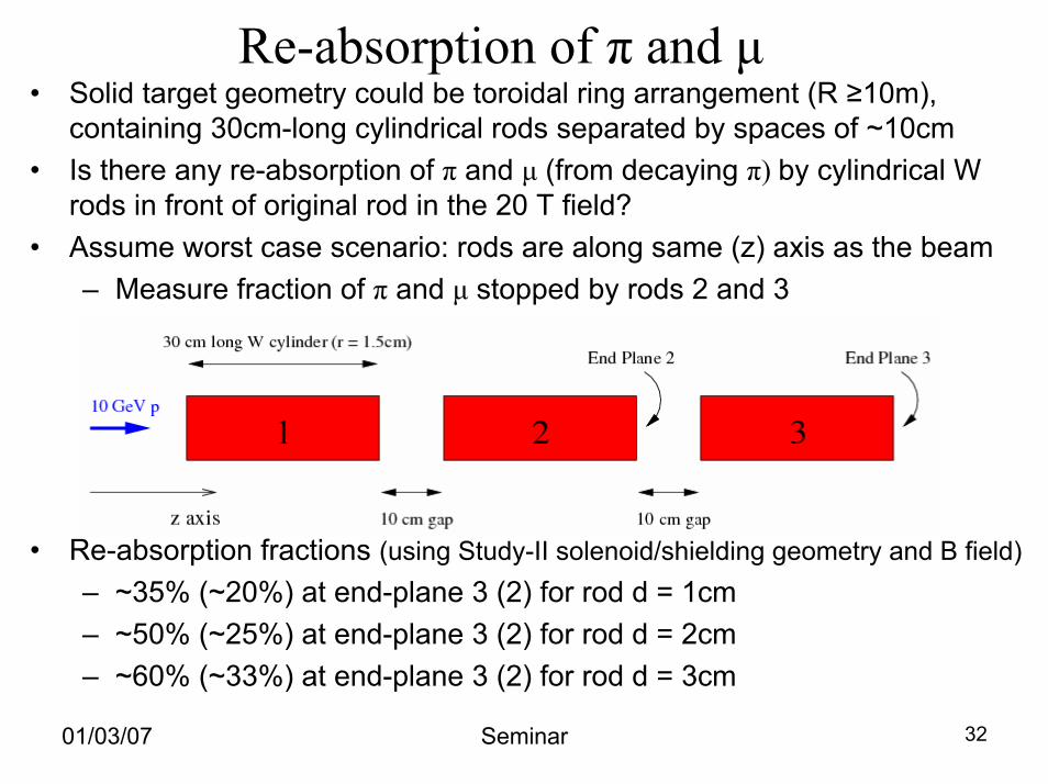
• Solid target geometry could be toroidal ring arrangement (R ≥10m), containing 30cm-long cylindrical rods separated by spaces of ~10cm
• Is there any re-absorption of π and µ (from decaying π) by cylindrical W rods in front of original rod in the 20 T field?
• Assume worst case scenario: rods are along same (z) axis as the beam – Measure fraction of π and µ stopped by rods 2 and 3
• Re-absorption fractions (using Study-II solenoid/shielding geometry and B field)– ~35% (~20%) at end-plane 3 (2) for rod d = 1cm– ~50% (~25%) at end-plane 3 (2) for rod d = 2cm– ~60% (~33%) at end-plane 3 (2) for rod d = 3cm
Re-absorption of π and µ
01/03/07 Seminar 32
Other R&D Work• End-to-end simulations of the ν Factory (ASTeC group@RAL)
– Accelerator schemes for protons and muons
• Muon Ionisation Cooling Experiment @ RAL– Need to reduce size of muon beam to accelerate it to required energies (10-
50GeV) before it decays to ν– Pass muon beam through absorber to reduce transverse momentum, accelerate
it along the z axis to the next absorber– Repeat until the transverse spread of the beam is reduced so that the beam can
fit inside accelerator components downstream
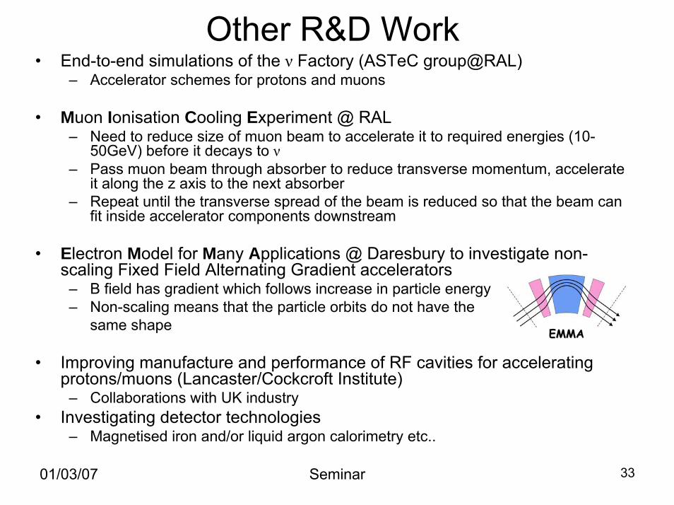
• Electron Model for Many Applications @ Daresbury to investigate non-scaling Fixed Field Alternating Gradient accelerators
– B field has gradient which follows increase in particle energy– Non-scaling means that the particle orbits do not have the
same shape
• Improving manufacture and performance of RF cavities for accelerating protons/muons (Lancaster/Cockcroft Institute)
– Collaborations with UK industry• Investigating detector technologies
– Magnetised iron and/or liquid argon calorimetry etc..
EMMAEMMA
01/03/07 Seminar 33
International Scoping Study
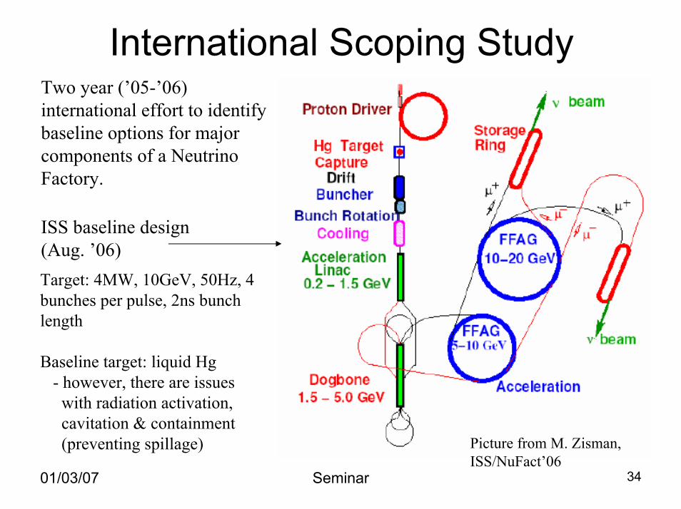
Target: 4MW, 10GeV, 50Hz, 4 bunches per pulse, 2ns bunch length
Baseline target: liquid Hg- however, there are issueswith radiation activation,cavitation & containment(preventing spillage)
Two year (’05-’06) international effort to identify baseline options for major components of a Neutrino Factory.
ISS baseline design(Aug. ’06)
01/03/07 Seminar 34
Picture from M. Zisman,ISS/NuFact’06
Summary• Neutrino Factory is the best way to measure properties
of neutrinos– Increase understanding of the flavour sector of the Standard
Model
• Shown part of the UK R&D efforts for a future Neutrino Factory– All aspects of a Neutrino Factory are being studied in the UK:
proton driver, target, end-to-end simulations, muon cooling, accelerator schemes, RF cavity construction and detectors.
– UK expertise in designing and constructing such a facility
• International Design Study (IDS) is starting, continuing on from the International Scoping Study (ISS)– Aim to have design report written by ~2012 (5 yr programme)– UK is playing a major role in this effort.
01/03/07 Seminar 35
Extra Material
01/03/07 Seminar 36
FETS TeamJohn Back (Warwick) - LEBTAaron Cheng (Imperial) – RF MeasurementsMike Clarke-Gayther (ISIS/ASTeC) – MEBT (Chopper)Adeline Daly (ISIS) – Infrastructure (R8 @ RAL)Dan Faircloth (ISIS) – Ion SourceChristoph Gabor (ASTeC) – Laser DiagnosticsSimon Jolly (Imperial) – Pepperpot System (LEBT)Ajit Kurup (Imperial) - RFQDavid Lee (Imperial) – Laser DiagnosticsAlan Letchford (ISIS) – Project Leader/RFQCiprian Plostinar (ASTeC) – MEBT/Drift Tube Linac (DTL)Jürgen Pozimski (ASTeC/Imperial) – Ion S., LEBT, RFQ, Diag.Peter Savage (Imperial) – Mechanical Engineer
01/03/07 Seminar 37
01/03/07 Seminar 38
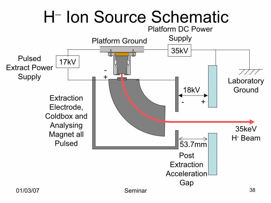
53.7mm
35kV17kV
Platform GroundPlatform DC Power
Supply
Post Extraction
Acceleration Gap
Laboratory Ground
Extraction Electrode,
Coldbox and Analysing Magnet all
Pulsed
Pulsed Extract Power
Supply
35keV H- Beam
+-
+-18kV
H− Ion Source Schematic
01/03/07 Seminar 39
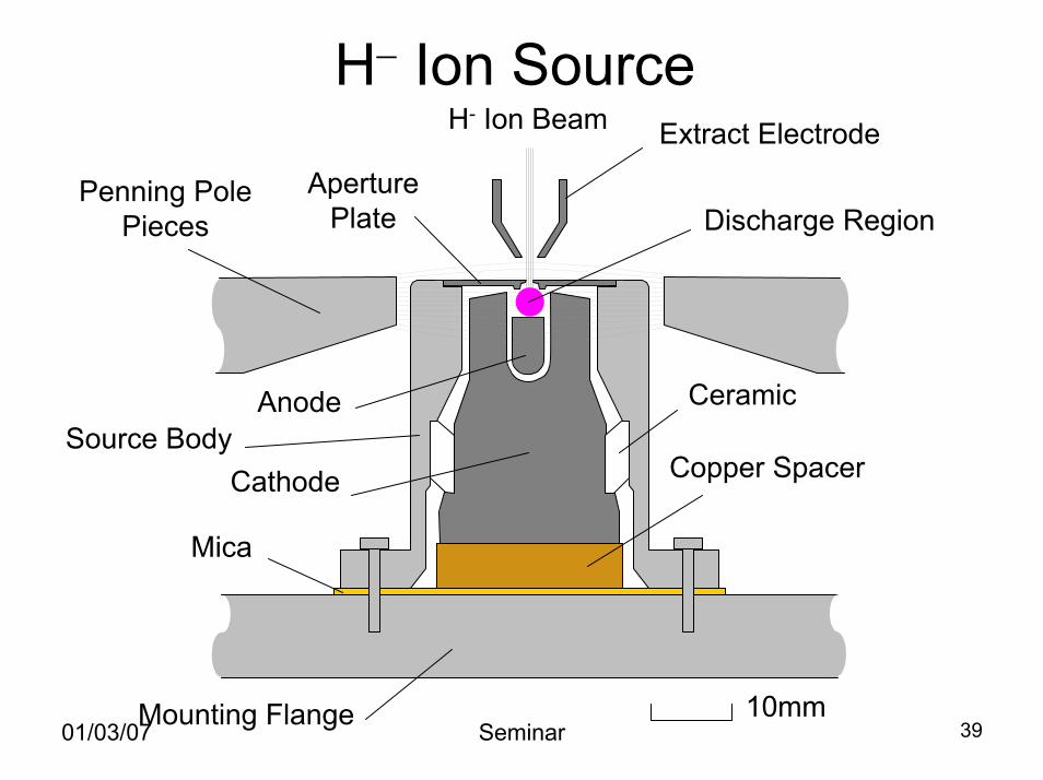
Mica
Mounting Flange
Copper Spacer
Ceramic
H- Ion Beam Extract Electrode
Cathode
Anode
Penning Pole Pieces Discharge Region
Aperture Plate
Source Body
H− Ion Source
10mm
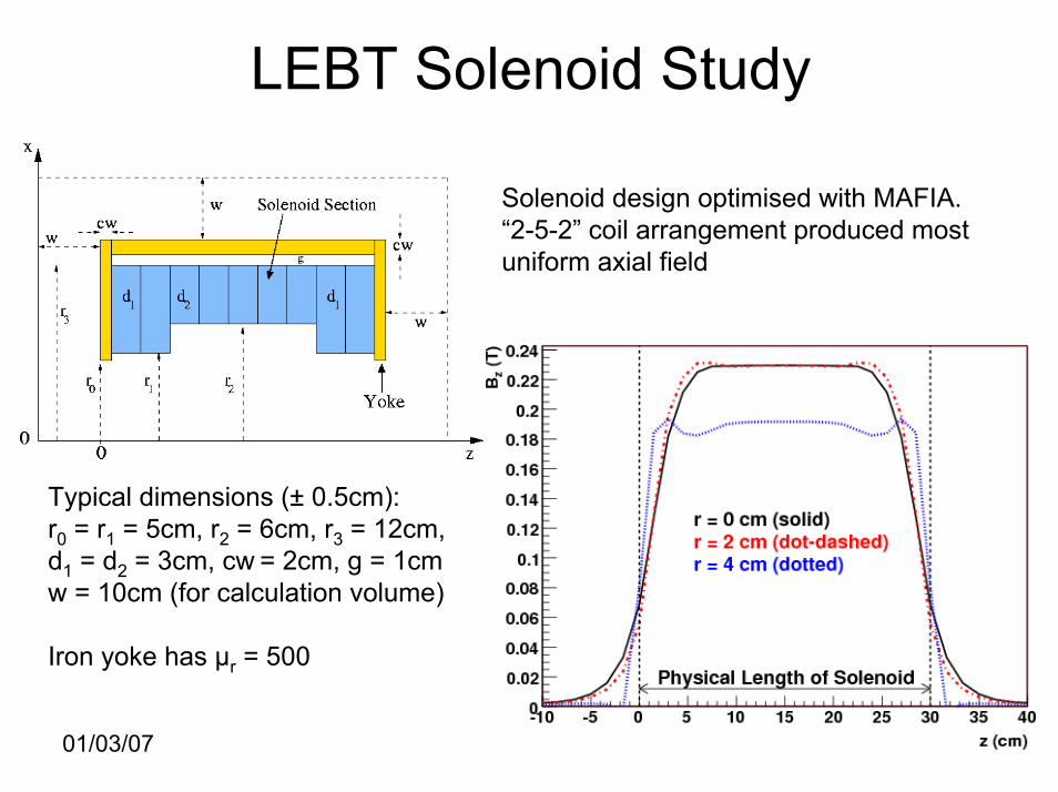
LEBT Solenoid Study
01/03/07 Seminar 40
Solenoid design optimised with MAFIA.“2-5-2” coil arrangement produced most uniform axial field
Typical dimensions (± 0.5cm):r0 = r1 = 5cm, r2 = 6cm, r3 = 12cm,d1 = d2 = 3cm, cw = 2cm, g = 1cmw = 10cm (for calculation volume)
Iron yoke has µr = 500
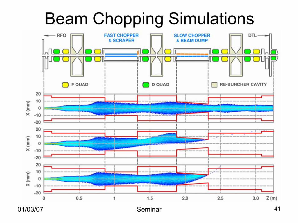
Beam Chopping Simulations
01/03/07 Seminar 41
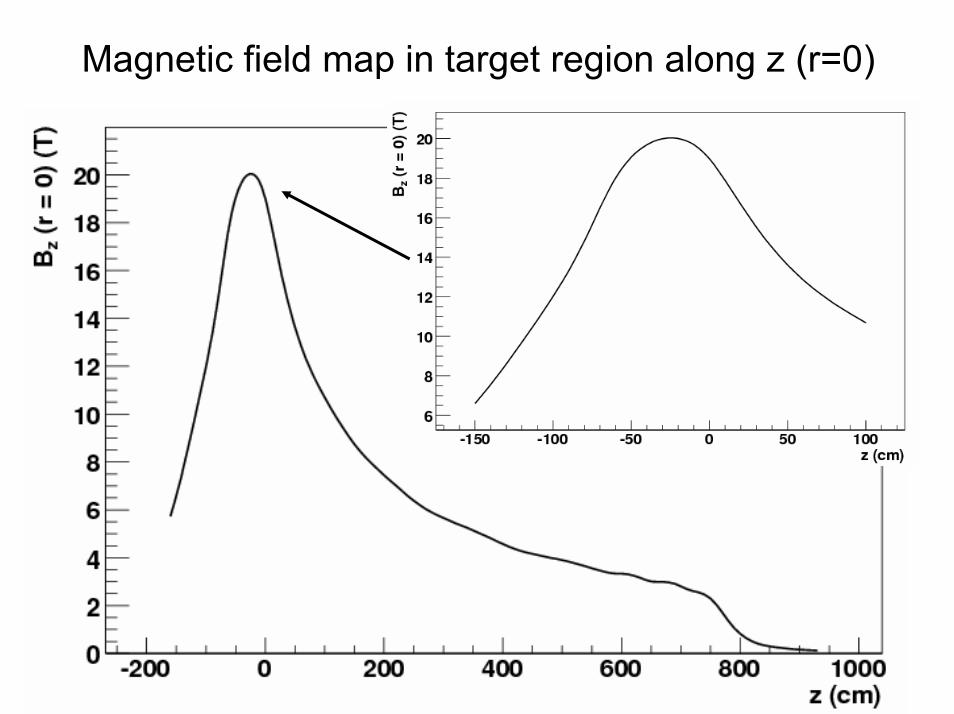
Magnetic field map in target region along z (r=0)
01/03/07 Seminar 42