NeSSI*: Defining an Intrinsically Safe Sensor/Actuator ...
30
NeSSI*: Defining an Intrinsically Safe Sensor/Actuator Network for Hazardous Areas NIST July 30, 2003 Rob Dubois C PL C “the best way to predict the future is to create it” *New Sampling/Sensor Initiative
Transcript of NeSSI*: Defining an Intrinsically Safe Sensor/Actuator ...
NeSSI*: Defining an Intrinsically SafeSensor/Actuator Network for Hazardous Areas
NISTJuly 30, 2003
Rob Dubois
C PΛΛ C
“the best way to predict the future is to create it”
*New Sampling/Sensor Initiative
2
Presentation Outline
• Today’s Process Analytical Technology vs. theNeSSI Vision of Success
• A Quick Look at Electrically HazardousEnvironments and Methods of Protection
• NeSSI Development Roadmap & Generations• Key Aspects of the NeSSI Gen II Networking
Requirements and Specification• Summary
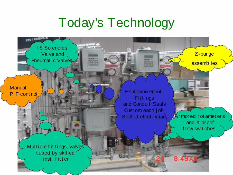
Explosion Proof Fittings
and Conduit SealsCustom each job
Skilled electrician
Multiple fittings, valvestubed by skilled
inst. fitter
IS Solenoids Valve and
Pneumatic ValvesZ-purge
assemblies
Today’s Technology
Armored rotameters and X proof
flow switches
ManualP, F control
4
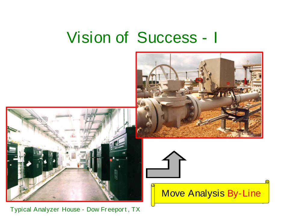
Vision of Success - I
Move Analysis By-LineTypical Analyzer House - Dow Freeport, TX
5
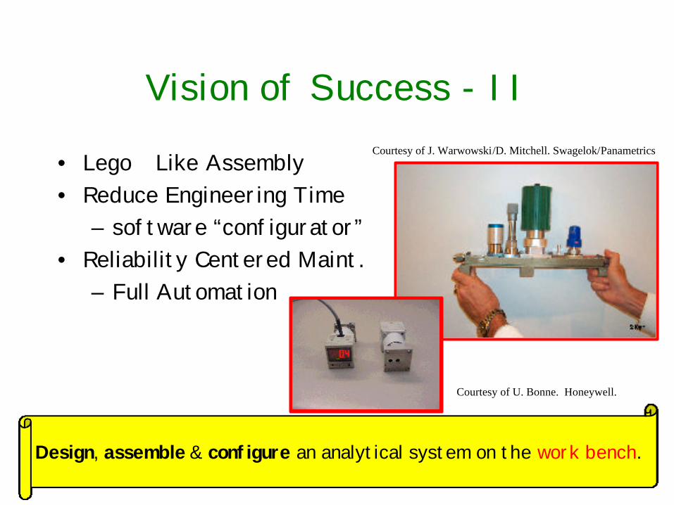
Vision of Success - II
• Lego Like Assembly• Reduce Engineering Time
– software “configurator”• Reliability Centered Maint.
– Full Automation
Design, assemble & configure an analytical system on the work bench.
Courtesy of J. Warwowski/D. Mitchell. Swagelok/Panametrics
Courtesy of U. Bonne. Honeywell.
6
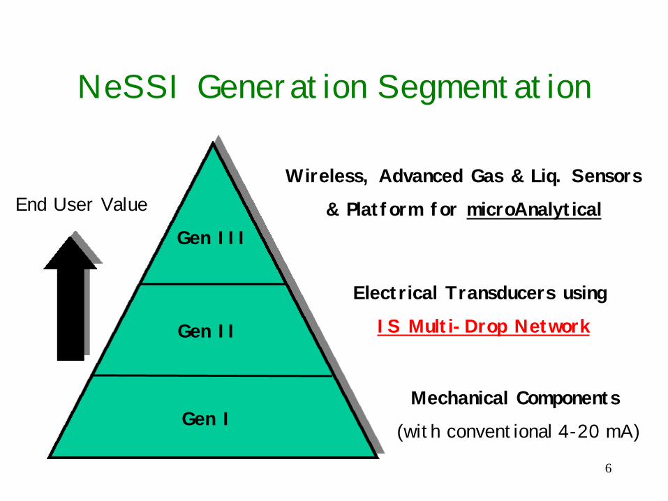
NeSSI Generation Segmentation
Gen III
Gen II
Gen IMechanical Components
(with conventional 4-20 mA)
Electrical Transducers using
IS Multi-Drop Network
Wireless, Advanced Gas & Liq. Sensors
& Platform for microAnalytical End User Value
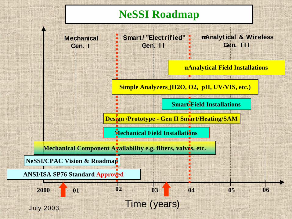
Time (years)
03 04
NeSSI Roadmap
02
Mechanical Component Availability e.g. filters, valves, etc.
Mechanical Field Installations
ANSI/ISA SP76 Standard Approved
NeSSI/CPAC Vision & Roadmap
2000
Design /Prototype - Gen II Smart/Heating/SAM
Smart Field Installations
MechanicalGen. I
Smart/”Electrified”Gen. II
µµAnalytical & WirelessGen. III
01 0605
July 2003
uAnalytical Field Installations
Simple Analyzers (H2O, O2, pH, UV/VIS, etc.)
8
The Penitent - We’ve come along way!
Courtesy of Health and Safety Executive, Sheffield, England
9
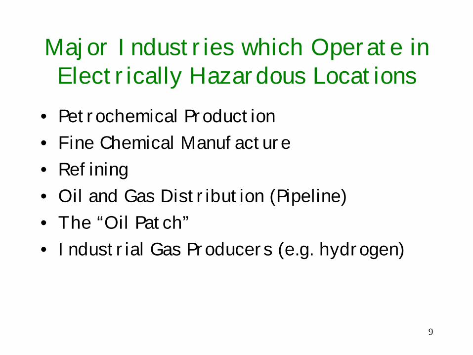
Major Industries which Operate inElectrically Hazardous Locations
• Petrochemical Production• Fine Chemical Manufacture• Refining• Oil and Gas Distribution (Pipeline)• The “Oil Patch”• Industrial Gas Producers (e.g. hydrogen)
10
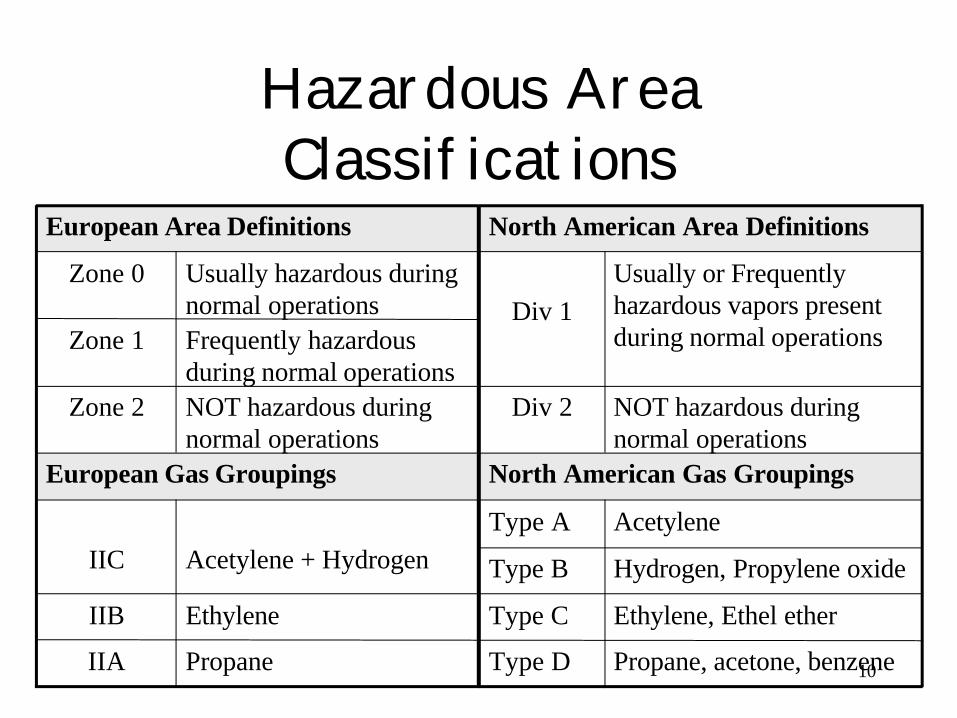
Hazardous AreaClassifications
North American Gas GroupingsEuropean Gas Groupings
NOT hazardous duringnormal operations
Div 2NOT hazardous duringnormal operations
Zone 2
Propane, acetone, benzeneType DPropaneIIA
Ethylene, Ethel etherType CEthyleneIIB
Hydrogen, Propylene oxideType B
AcetyleneType A
Acetylene + HydrogenIIC
Frequently hazardousduring normal operations
Zone 1
Usually or Frequentlyhazardous vapors presentduring normal operations
Div 1
Usually hazardous duringnormal operations
Zone 0
North American Area DefinitionsEuropean Area Definitions
11
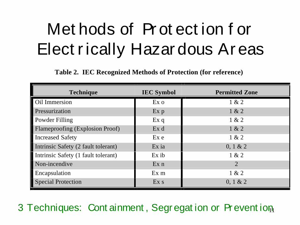
Methods of Protection forElectrically Hazardous Areas
Table 2. IEC Recognized Methods of Protection (for reference)
Technique IEC Symbol Permitted Zone
Oil Immersion Ex o 1 & 2
Pressurization Ex p 1 & 2
Powder Filling Ex q 1 & 2
Flameproofing (Explosion Proof) Ex d 1 & 2
Increased Safety Ex e 1 & 2
Intrinsic Safety (2 fault tolerant) Ex ia 0, 1 & 2
Intrinsic Safety (1 fault tolerant) Ex ib 1 & 2
Non-incendive Ex n 2
Encapsulation Ex m 1 & 2
Special Protection Ex s 0, 1 & 2
3 Techniques: Containment, Segregation or Prevention
12
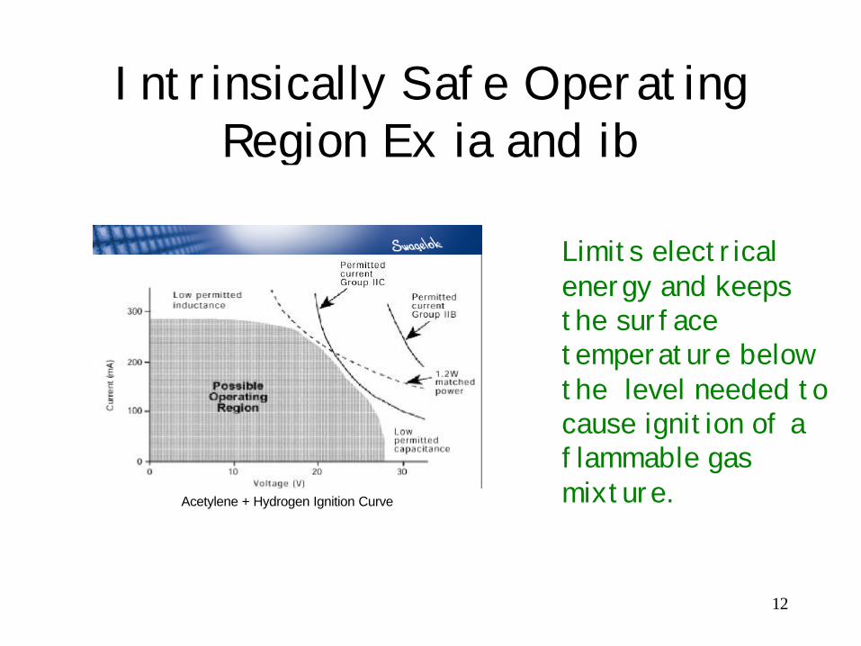
Intrinsically Safe OperatingRegion Ex ia and ib
Acetylene + Hydrogen Ignition Curve
Limits electricalenergy and keepsthe surfacetemperature belowthe level needed tocause ignition of aflammable gasmixture.
13
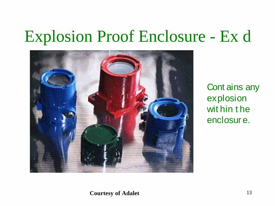
Explosion Proof Enclosure - Ex d
Courtesy of Adalet
Contains anyexplosionwithin theenclosure.
14
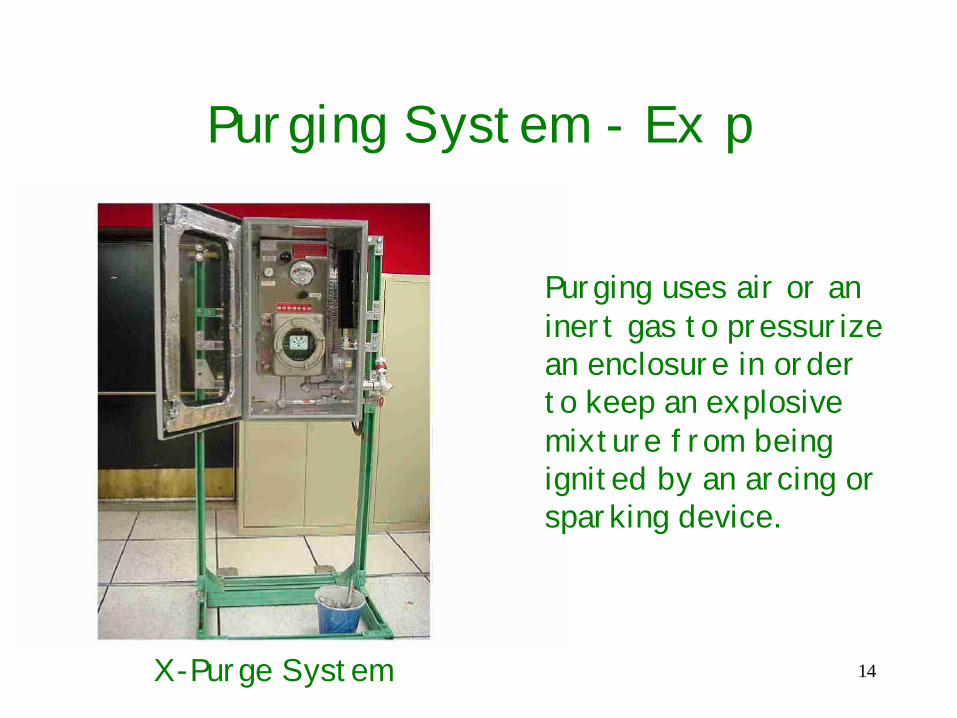
Purging System - Ex p
Purging uses air or aninert gas to pressurizean enclosure in orderto keep an explosivemixture from beingignited by an arcing orsparking device.
X-Purge System
15
Key Aspects of the NeSSI GenII Specification
A Conceptual and Functional Specification Describing the Use of Miniature, Modular (and Smart) Electrical Components for adaptation to the ANSI/ISA SP76 Substratein Electrically Hazardous Environments
Please refer to Gen II Spec draft version d6...http://www.cpac.washington.edu/NeSSI/NeSSI.htm
16
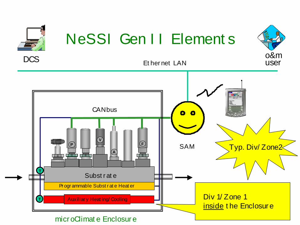
Programmable Substrate Heater
VP
A
F SAM
CANbus
Auxiliary Heating/Cooling
SubstrateT
T
Ethernet LANDCS o&muser
microClimate Enclosure
NeSSI Gen II Elements
Div 1/Zone 1inside the Enclosure
Typ. Div/Zone2
17
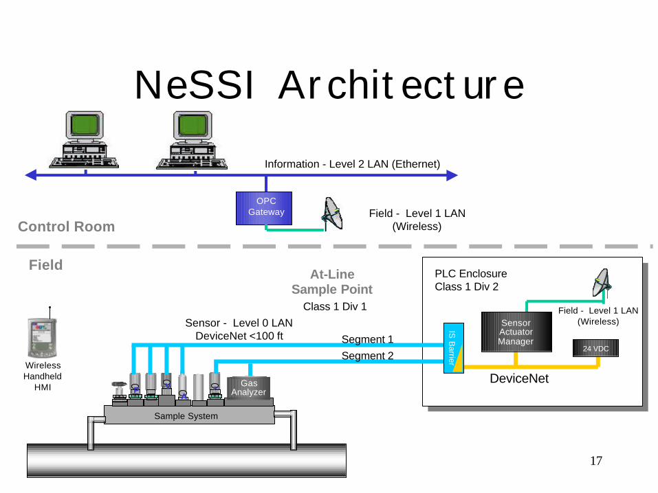
NeSSI Architecture
Sensor - Level 0 LANDeviceNet <100 ft
Information - Level 2 LAN (Ethernet)
OPCGateway
V TPA
Sample System
Control Room
At-LineSample Point
PLC Enclosure Class 1 Div 2
Class 1 Div 1
WirelessHandheld
HMI GasAnalyzer
Field
Field - Level 1 LAN(Wireless)
Field - Level 1 LAN(Wireless)
DeviceNet
Segment 1
Segment 2
IS B
arrier
SensorActuatorManager
24 VDC
18
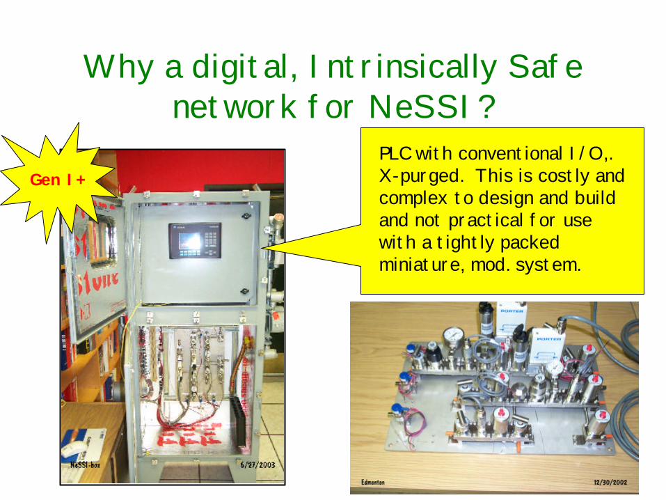
Why a digital, Intrinsically Safenetwork for NeSSI?
PLC with conventional I/O,.X-purged. This is costly andcomplex to design and buildand not practical for usewith a tightly packedminiature, mod. system.
Gen I+
19
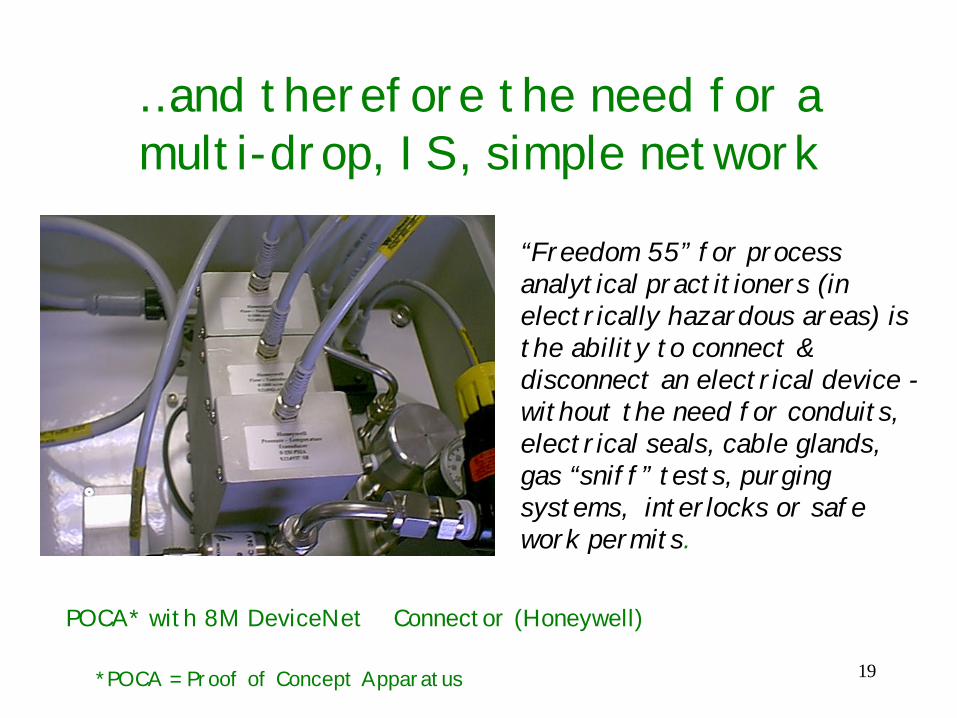
…and therefore the need for amulti-drop, IS, simple network
POCA* with 8M DeviceNet Connector (Honeywell)
“Freedom 55” for processanalytical practitioners (inelectrically hazardous areas) isthe ability to connect &disconnect an electrical device -without the need for conduits,electrical seals, cable glands,gas “sniff” tests, purgingsystems, interlocks or safework permits.
*POCA = Proof of Concept Apparatus
20
Global Certification of theNetwork - single agency
• Approved for all Zone and Divisiongeographies. (ATEX, UL, CSA)
• Why Intrinsically Safe?– Best safety for high risk areas (eg. inside an
enclosure handling hazardous, flowing fluidssuch as ethylene.)
– A globally approved method of protection– However, the most compelling reason for IS is
the ability to use plug and play miniature,modular sensors using “normal” wiring.
21
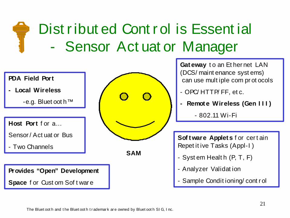
Gateway to an Ethernet LAN(DCS/maintenance systems) can use multiple com protocols
- OPC/HTTP/FF, etc.
- Remote Wireless (Gen III)
- 802.11 Wi-FiHost Port for a…
Sensor/Actuator Bus
- Two Channels
PDA Field Port
- Local Wireless
-e.g. Bluetooth™
Software Applets for certainRepetitive Tasks (Appl-I)
- System Health (P, T, F)
- Analyzer Validation
- Sample Conditioning/controlProvides “Open” Development
Space for Custom Software
SAM
The Bluetooth and the Bluetooth trademark are owned by Bluetooth SIG, Inc.
Distributed Control is Essential- Sensor Actuator Manager
22
Maximizing the Number ofNetwork Devices is Essential
• NeSSI Gen II spec suggests a min. of 25devices per channel/port for a Class IIC(worst case) hazardous environment– makes a system cost-effective– allows sharing among analytical systems– simplifies installations– justifies the use of multiple sensors
23
A Single, Low Voltage Power SupplyIntegrated with an IS Barrier
• Minimizes complexity (packaging, wiring)• Low voltage assists power budget• Single voltage spec gives clear design
objective for component makers• Larger power supplies (e.g. 24 VDC takes
up precious space)• NeSSI suggests 12 VDC max.
24
Key Network Attributes
• Hot Disconnect (w/o shutting down)• Distance (typ within 30’ - max. 500’)• Approx. 10 updates/second
– physical (analogue) transducers (P, T, F,Vo, Vm) - low data throughput
– microAnalytical (chromatography,spectroscopy) - high data throughput
• Mission Critical Performance in aRobust Environment
25
Key Transducer-NetworkAttributes
• Industry standard connector• Simple diagnostics (traffic light analogy)• Simple Configuration
– Transducer Ambiguous• Low cost - “Open” and Interoperable• Optical isolation [for certain devices which
may need to be powered remotely]
26
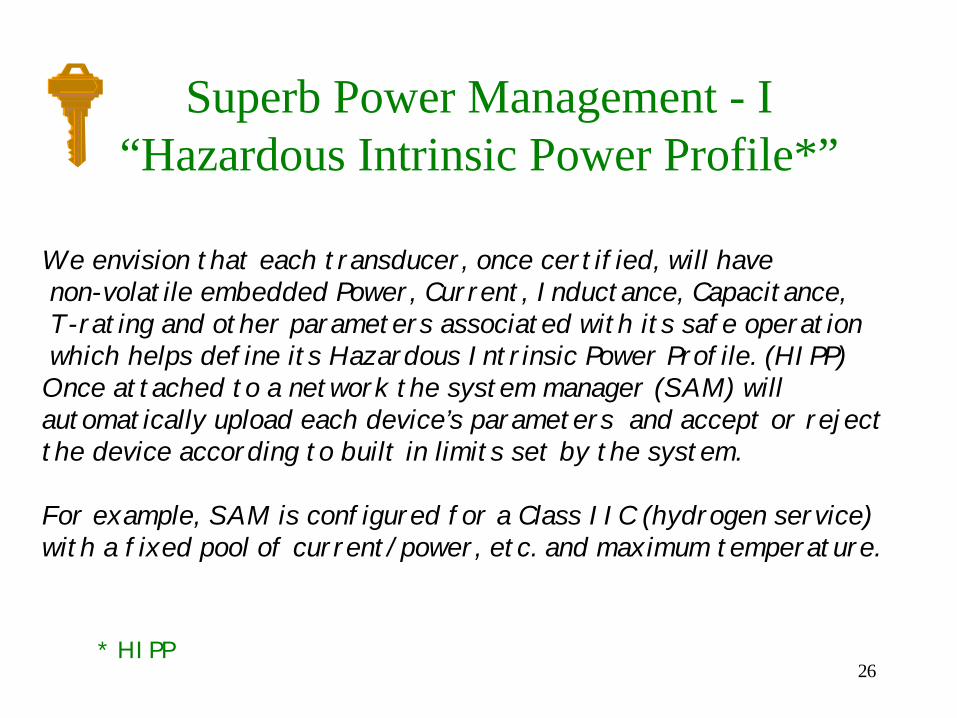
Superb Power Management - I“Hazardous Intrinsic Power Profile*”
* HIPP
We envision that each transducer, once certified, will have non-volatile embedded Power, Current, Inductance, Capacitance, T-rating and other parameters associated with its safe operation which helps define its Hazardous Intrinsic Power Profile. (HIPP) Once attached to a network the system manager (SAM) willautomatically upload each device’s parameters and accept or rejectthe device according to built in limits set by the system.
For example, SAM is configured for a Class IIC (hydrogen service)with a fixed pool of current/power, etc. and maximum temperature.
27
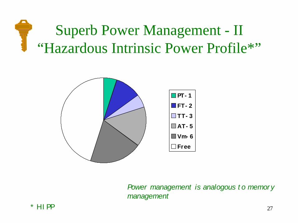
Superb Power Management - II“Hazardous Intrinsic Power Profile*”
Power management is analogous to memorymanagement
PT-1FT-2TT-3AT-5Vm-6Free
* HIPP
28
User Friendly Network
• Adding a component to the networkshould be a simple & quick task.– Maintenance time is spread thin - a
cumbersome or inflexible interface orneeding expert assistance, for a simplejob, will not be well accepted.
• Wireless transmission for local andremote communication.
29
Related Applications
• Pilot Plants/MicroReactors• Laboratories• Low Power Applications
– battery powered systems– wireless– remote systems
• Auxiliary analytical systems– heat tracing
30
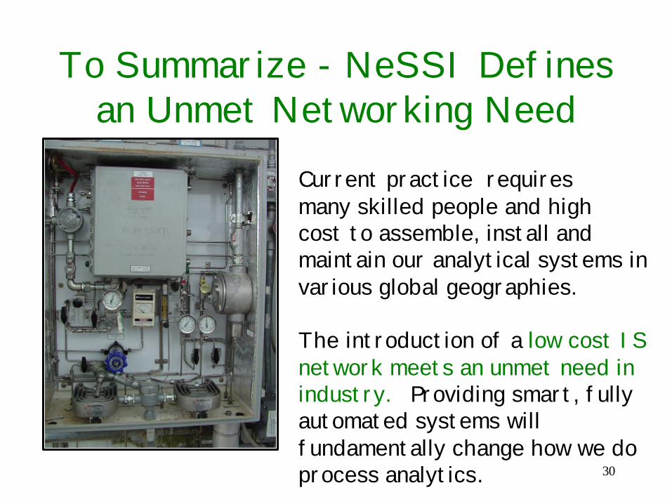
To Summarize - NeSSI Definesan Unmet Networking Need
Current practice requiresmany skilled people and high cost to assemble, install andmaintain our analytical systems invarious global geographies. The introduction of a low cost ISnetwork meets an unmet need in industry. Providing smart, fullyautomated systems willfundamentally change how we doprocess analytics.