
N368E prEN 1991-1-4-tc4
30
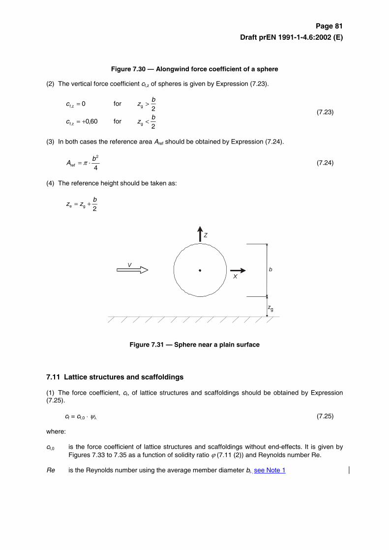
Page 81 Draft prEN 1991-1-4.6:2002 (E) Figure 7.30 — Alongwind force coefficient of a sphere (2) The vertical force coefficient c f,z of spheres is given by Expression (7.23). 2 for 60 , 0 2 for 0 g f,z g f,z b z c b z c < + = > = (7.23) (3) In both cases the reference area A ref should be obtained by Expression (7.24). 4 2 ref b A ⋅ = π (7.24) (4) The reference height should be taken as: 2 g e b z z + = Figure 7.31 — Sphere near a plain surface 7.11 Lattice structures and scaffoldings (1) The force coefficient, c f , of lattice structures and scaffoldings should be obtained by Expression (7.25). c f = c f,0 ⋅ ψ λ (7.25) where: c f,0 is the force coefficient of lattice structures and scaffoldings without end-effects. It is given by Figures 7.33 to 7.35 as a function of solidity ratio ϕ (7.11 (2)) and Reynolds number Re. Re is the Reynolds number using the average member diameter b i , see Note 1
-
Upload
najibkiwan -
Category
Documents
-
view
67 -
download
3
description
N368E prEN 1991-1-4-tc4
Transcript of N368E prEN 1991-1-4-tc4
Page 81
Draft prEN 1991-1-4.6:2002 (E)
Figure 7.30 — Alongwind force coefficient of a sphere
(2) The vertical force coefficient cf,z of spheres is given by Expression (7.23).
2for60,0
2for0
gf,z
gf,z
bzc
bzc
<+=
>= (7.23)
(3) In both cases the reference area Aref should be obtained by Expression (7.24).
4
2
ref
bA ⋅= π (7.24)
(4) The reference height should be taken as:
2ge
bzz +=
Figure 7.31 — Sphere near a plain surface
7.11 Lattice structures and scaffoldings
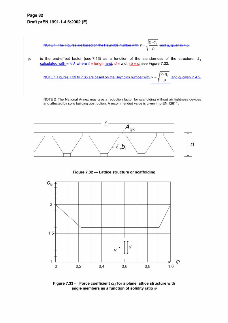
(1) The force coefficient, cf, of lattice structures and scaffoldings should be obtained by Expression (7.25).
cf = cf,0 ⋅ ψλ (7.25)
where:
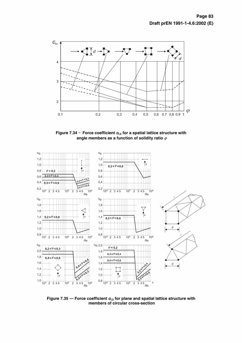
cf,0 is the force coefficient of lattice structures and scaffoldings without end-effects. It is given by Figures 7.33 to 7.35 as a function of solidity ratio ϕ (7.11 (2)) and Reynolds number Re.
Re is the Reynolds number using the average member diameter bi , see Note 1
Page 82
Draft prEN 1991-1-4.6:2002 (E)
NOTE 1 The Figures are based on the Reynolds number with ρ
p2 qv
⋅= and qp given in 4.5.
ψλ is the end-effect factor (see 7.13) as a function of the slenderness of the structure, λ , calculated with = l/d, where l = length and, d = width b = d, see Figure 7.32.
NOTE 1 Figures 7.33 to 7.35 are based on the Reynolds number with ρ
p2 qv
⋅= and qp given in 4.5.
NOTE 2 The National Annex may give a reduction factor for scaffolding without air tightness devices and affected by solid building obstruction. A recommended value is given in prEN 12811.
Figure 7.32 — Lattice structure or scaffolding
Figure 7.33 — Force coefficient cf,0 for a plane lattice structure with angle members as a function of solidity ratio ϕ
Page 83
Draft prEN 1991-1-4.6:2002 (E)
Figure 7.34 — Force coefficient cf,0 for a spatial lattice structure with angle members as a function of solidity ratio ϕ
Figure 7.35 — Force coefficient cf,0 for plane and spatial lattice structure with members of circular cross-section
Page 84
Draft prEN 1991-1-4.6:2002 (E)
(2) The solidity ratio, ϕ, is defined by Expression (7.26).
cA
A=ϕ (7.26)
where:
A is the sum of the projected area of the members and gusset plates of the face projected normal to the face: ∑∑ +⋅=
kgki
ii AbA l
Ac is the the area enclosed by the boundaries of the face projected normal to the face = d l
l is the length of the lattice
d is the width of the lattice
bi, li is the width and length of the individual member i (see Figure 7.32), projected normal to the face
Agk is the area of the gusset plate k
(3) The reference area Aref should be determined by Expression (7.27)
AA =ref (7.27)
(4) The reference height ze is equal to the maximum height of the element above ground.
7.12 Flags
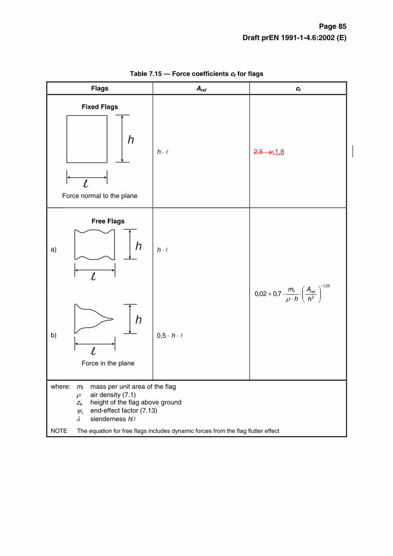
(1) Force coefficients cf and reference areas Aref for flags are given in Table 7.15.
(2) The reference height ze is equal to the height of the flag above ground.
Page 85
Draft prEN 1991-1-4.6:2002 (E)
Table 7.15 — Force coefficients cf for flags
Flags Aref cf
Fixed Flags
Force normal to the plane
h ⋅ l 2,5 ⋅ ψλ1,8
a)
Free Flags
h
h ⋅ l
b)
Force in the plane
0,5 ⋅ h ⋅ l
25,1
2reff7,002,0
−
⋅⋅
⋅+h
A
h
m
ρ
where: mf mass per unit area of the flag ρ air density (7.1) ze height of the flag above ground ψλ end-effect factor (7.13) λ slenderness h/l
NOTE The equation for free flags includes dynamic forces from the flag flutter effect
Page 86
Draft prEN 1991-1-4.6:2002 (E)
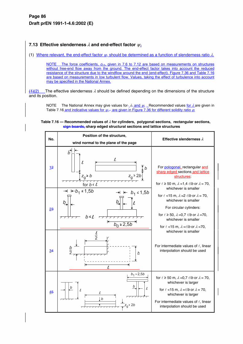
7.13 Effective slenderness λ and end-effect factor ψλ
(1) Where relevant, the end-effect factor ψ λ should be determined as a function of slenderness ratio λ.
NOTE The force coefficients, cf,0, given in 7.6 to 7.12 are based on measurements on structures without free-end flow away from the ground. The end-effect factor takes into account the reduced resistance of the structure due to the windflow around the end (end-effect). Figure 7.36 and Table 7.16 are based on measurements in low turbulent flow. Values, taking the effect of turbulence into account may be specified in the National Annex.
(1)(2) The effective slenderness λ should be defined depending on the dimensions of the structure and its position.
NOTE The National Annex may give values for λ. and ψ λ . Recommended values for λ are given in Table 7.16 and indicative values for ψ λ. are given in Figure 7.36 for different solidity ratio ϕ.
Table 7.16 — Recommended values of λ for cylinders, polygonal sections, rectangular sections, sign boards, sharp edged structural sections and lattice structures
No. Position of the structure,
wind normal to the plane of the page Effective slenderness λ
12
23
34
For pologonal, rectangular and sharp edged sections and lattice
structures:
for l ≥ 50 m, λ =1,4 l/b or λ = 70, whichever is smaller
for l <15 m, λ =2 l/b or λ = 70, whichever is smaller
For circular cylinders:
for l ≥ 50, λ =0,7 l/b or λ =70, whichever is smaller
for l <15 m, λ =l/b or λ =70, whichever is smaller
For intermediate values of l, linear interpolation should be used
45
for l ≥ 50 m, λ =0,7 l/b or λ = 70, whichever is larger
for l <15 m, λ =l/b or λ = 70, whichever is larger
For intermediate values of l, linear interpolation should be used
Page 87
Draft prEN 1991-1-4.6:2002 (E)
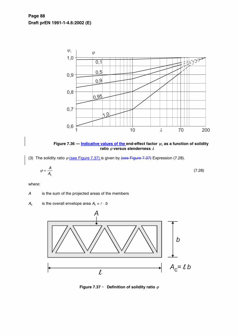
(2)The end-effect factor ψλ, is given as a function of slenderness ratio λ, for different solidity ratio ϕ, in Figure 7.36
NOTE The force coefficients cf,0 of Clauses 7.6 to 7.12 are based on measurements on structures without free-end flow away from the ground. The end-effect factor takes into account the reduced resistance of the structure due to the windflow around the end (end-effect). Figure 7.36 and Table 7.16 are based on measurements in low turbulent flow. Values, taking the effect of turbulence into account may be specified in the National Annex.
Page 88
Draft prEN 1991-1-4.6:2002 (E)
Figure 7.36 — Indicative values of the end-effect factor ψλ as a function of solidity ratio ϕ versus slenderness λ
(3) The solidity ratio ϕ (see Figure 7.37) is given by (see Figure 7.37) Expression (7.28).
cA
A=ϕ (7.28)
where:
A is the sum of the projected areas of the members
Ac is the overall envelope area Ac = l ⋅ b
Figure 7.37 — Definition of solidity ratio ϕ
Page 89
Draft prEN 1991-1-4.6:2002 (E)
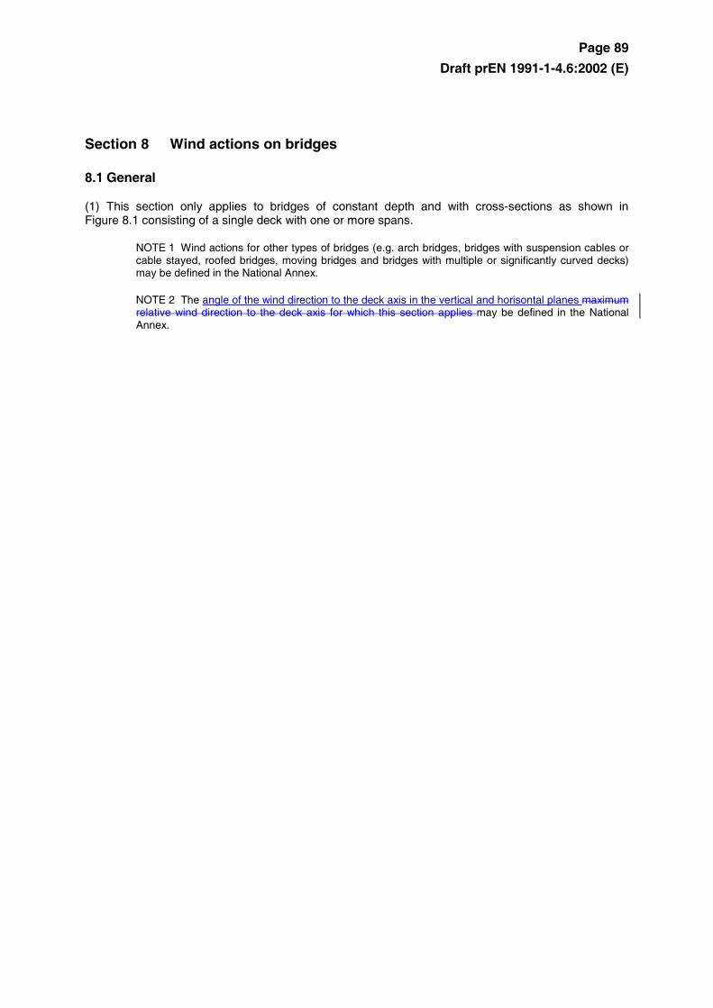
Section 8 Wind actions on bridges
8.1 General
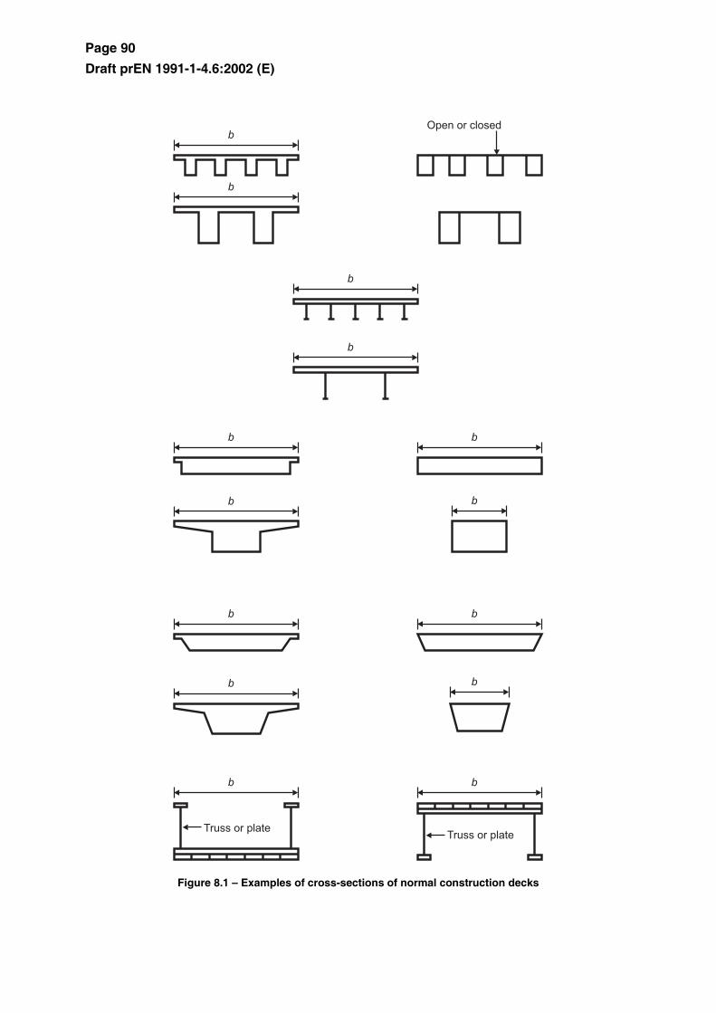
(1) This section only applies to bridges of constant depth and with cross-sections as shown in Figure 8.1 consisting of a single deck with one or more spans.
NOTE 1 Wind actions for other types of bridges (e.g. arch bridges, bridges with suspension cables or cable stayed, roofed bridges, moving bridges and bridges with multiple or significantly curved decks) may be defined in the National Annex.
NOTE 2 The angle of the wind direction to the deck axis in the vertical and horisontal planes maximum relative wind direction to the deck axis for which this section applies may be defined in the National Annex.
Page 90
Draft prEN 1991-1-4.6:2002 (E)
Figure 8.1 – Examples of cross-sections of normal construction decks
Page 91
Draft prEN 1991-1-4.6:2002 (E)
(2) Wind forces exerted on decks are dealt with in 8.2 and 8.3. Those exerted on piers are dealt with in 8.4. The forces exerted on various parts of a bridge due to wind blowing in the same direction should be considered as simultaneous if they are unfavourable.
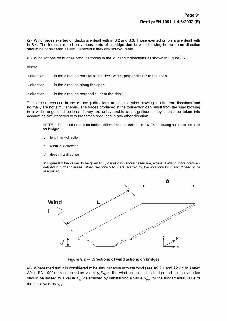
(3) Wind actions on bridges produce forces in the x, y and z directions as shown in Figure 8.2,
where:
x-direction is the direction parallel to the deck width, perpendicular to the span
y-direction is the direction along the span
z-direction is the direction perpendicular to the deck
The forces produced in the x- and y-directions are due to wind blowing in different directions and normally are not simultaneous. The forces produced in the z-direction can result from the wind blowing in a wide range of directions; if they are unfavourable and significant, they should be taken into account as simultaneous with the forces produced in any other direction.
NOTE The notation used for bridges differs from that defined in 1.6. The following notations are used for bridges:
L length in y-direction
b width in x-direction
d depth in z-direction
In Figure 8.2 the values to be given to L, b and d in various cases are, where relevant, more precisely defined in further clauses. When Sections 5 to 7 are referred to, the notations for b and d need to be readjusted.
Figure 8.2 — Directions of wind actions on bridges
(4) Where road traffic is considered to be simultaneous with the wind (see A2.2.1 and A2.2.2 in Annex A2 to EN 1990) the combination value ψ0Fwk of the wind action on the bridge and on the vehicles should be limited to a value *
WF determined by substituting a value *b,0v for the fundamental value of
the basic velocity vb,0.
Page 92
Draft prEN 1991-1-4.6:2002 (E)
NOTE The National Annex may give a value for *b,0v . The recommended value is 23 m/s.
(5) Where railway traffic is considered to be simultaneous with the wind (see A2.2.1 and A2.2.4 in Annex A2 to EN 1990) the combination value ψ0Fwk of the wind action on the bridge and on the trains should be limited to a value **
WF determined by substituting a value **b,0v for the fundamental value of
the basic velocity vb,0.
NOTE The value of **b,0v may be defined in the National Annex. The recommended value of **
b,0v is
25 m/sec.
8.2 Choice of the response calculation procedure
(1) It should be assessed whether a dynamic response procedure is needed for bridges.
NOTE 1 The National Annex may give criteria and procedures.
NOTE 2 If a dynamic response procedure is not needed, cscd may be taken equal to 1,0.
NOTE 3 For normal road and railway bridge decks of less than 40 m span a dynamic response procedure is generally not needed. For the purpose of this categorization, normal bridges may be considered to include bridges constructed in steel, concrete, aluminium or timber, including composite construction, and whose shape of cross sections is generally covered by Figure 8.1.
8.3 Force coefficients
(1) Force coeffcients for parapets and gantries on bridges should be determined were relevant.
NOTE The National Annex may give force coefficients for parapets and gantries on bridges. It is recommended to use Section 7.4.
8.3.1 Force coefficients in x-direction (general method)
(1) Force coefficients for wind actions on bridge decks in the x-direction are given by :
fx,0xf, cc = (8.1)
where:
cfx,0 is the force coefficient without free-end flow (see 7.13).
Page 93
Draft prEN 1991-1-4.6:2002 (E)
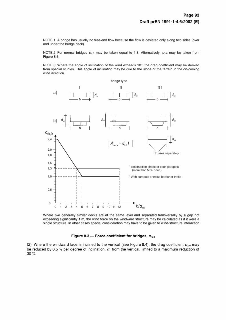
NOTE 1 A bridge has usually no free-end flow because the flow is deviated only along two sides (over and under the bridge deck).
NOTE 2 For normal bridges cfx,0 may be taken equal to 1,3. Alternatively, cfx,0 may be taken from Figure 8.3.
NOTE 3 Where the angle of inclination of the wind exceeds 10°, the drag coefficient may be derived from special studies. This angle of inclination may be due to the slope of the terrain in the on-coming wind direction.
Where two generally similar decks are at the same level and separated transversally by a gap not exceeding significantly 1 m, the wind force on the windward structure may be calculated as if it were a single structure. In other cases special consideration may have to be given to wind-structure interaction.
Figure 8.3 — Force coefficient for bridges, cfx,0
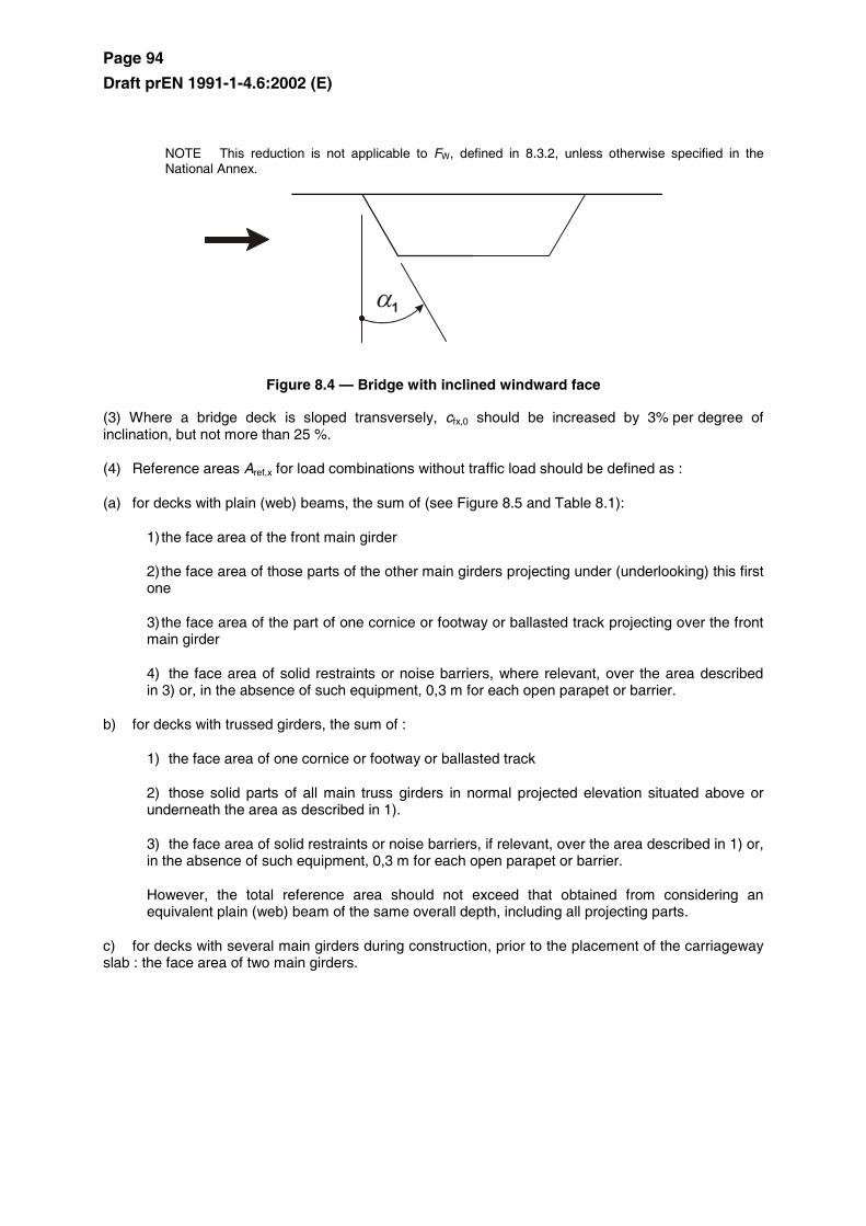
(2) Where the windward face is inclined to the vertical (see Figure 8.4), the drag coefficient cfx,0 may be reduced by 0,5 % per degree of inclination, α1 from the vertical, limited to a maximum reduction of 30 %.
Page 94
Draft prEN 1991-1-4.6:2002 (E)
NOTE This reduction is not applicable to FW, defined in 8.3.2, unless otherwise specified in the National Annex.
Figure 8.4 — Bridge with inclined windward face
(3) Where a bridge deck is sloped transversely, cfx,0 should be increased by 3% per degree of inclination, but not more than 25 %.
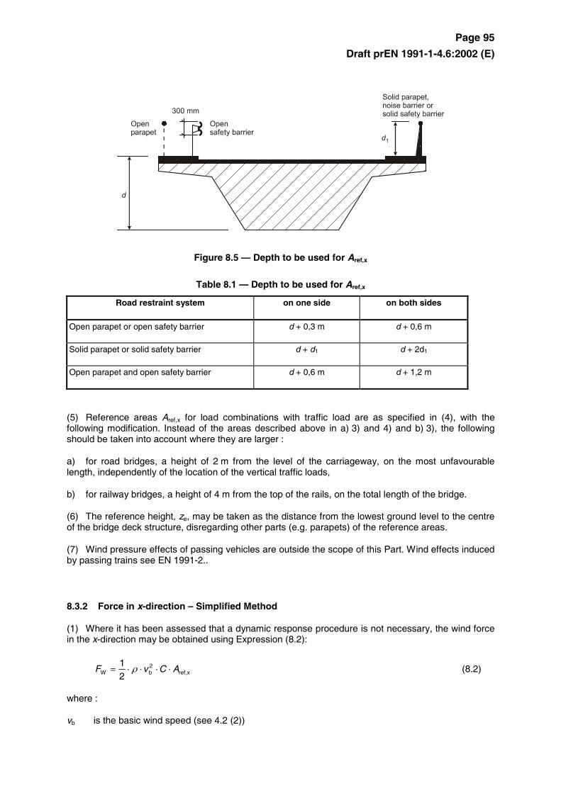
(4) Reference areas Aref,x for load combinations without traffic load should be defined as :
(a) for decks with plain (web) beams, the sum of (see Figure 8.5 and Table 8.1):
1) the face area of the front main girder
2) the face area of those parts of the other main girders projecting under (underlooking) this first one
3) the face area of the part of one cornice or footway or ballasted track projecting over the front main girder
4) the face area of solid restraints or noise barriers, where relevant, over the area described in 3) or, in the absence of such equipment, 0,3 m for each open parapet or barrier.
b) for decks with trussed girders, the sum of :
1) the face area of one cornice or footway or ballasted track
2) those solid parts of all main truss girders in normal projected elevation situated above or underneath the area as described in 1).
3) the face area of solid restraints or noise barriers, if relevant, over the area described in 1) or, in the absence of such equipment, 0,3 m for each open parapet or barrier.
However, the total reference area should not exceed that obtained from considering an equivalent plain (web) beam of the same overall depth, including all projecting parts.
c) for decks with several main girders during construction, prior to the placement of the carriageway slab : the face area of two main girders.
Page 95
Draft prEN 1991-1-4.6:2002 (E)
Figure 8.5 — Depth to be used for Aref,x
Table 8.1 — Depth to be used for Aref,x
Road restraint system on one side on both sides
Open parapet or open safety barrier d + 0,3 m d + 0,6 m
Solid parapet or solid safety barrier d + d1 d + 2d1
Open parapet and open safety barrier d + 0,6 m d + 1,2 m
(5) Reference areas Aref,x for load combinations with traffic load are as specified in (4), with the following modification. Instead of the areas described above in a) 3) and 4) and b) 3), the following should be taken into account where they are larger :
a) for road bridges, a height of 2 m from the level of the carriageway, on the most unfavourable length, independently of the location of the vertical traffic loads,
b) for railway bridges, a height of 4 m from the top of the rails, on the total length of the bridge.
(6) The reference height, ze, may be taken as the distance from the lowest ground level to the centre of the bridge deck structure, disregarding other parts (e.g. parapets) of the reference areas.
(7) Wind pressure effects of passing vehicles are outside the scope of this Part. Wind effects induced by passing trains see EN 1991-2..
8.3.2 Force in x-direction – Simplified Method
(1) Where it has been assessed that a dynamic response procedure is not necessary, the wind force in the x-direction may be obtained using Expression (8.2):
xref,2bW 2
1ACvF ⋅⋅⋅⋅= ρ (8.2)
where :
vb is the basic wind speed (see 4.2 (2))
Page 96
Draft prEN 1991-1-4.6:2002 (E)
C is the wind load factor. C = ce · cf,x, where ce is the exposure factor given in 4.5 and cf,x is given in 8.3.1(1)
Aref,x is the reference area given in 8.3.1
ρ is the density of air (see 4.5)
NOTE C-values may be defined in the National Annex. Recommended values are given in Table 8.2.
Page 97
Draft prEN 1991-1-4.6:2002 (E)
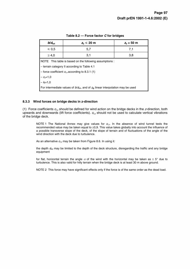
Table 8.2 — Force factor C for bridges
b/dtot ze 20 m ze = 50 m
0,5 5,7 7,1
≥ 4,0 3,1 3,8
NOTE This table is based on the following assumptions :
– terrain category II according to Table 4.1
– force coefficient cf,x according to 8.3.1 (1)
– co=1,0
– kI=1,0
For intermediate values of b/dtot, and of ze linear interpolation may be used
8.3.3 Wind forces on bridge decks in z-direction
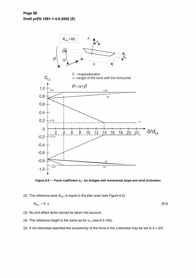
(1) Force coefficients cf,z should be defined for wind action on the bridge decks in the z-direction, both upwards and downwards (lift force coefficients). cf,z should not be used to calculate vertical vibrations of the bridge deck.
NOTE 1 The National Annex may give values for cf,z. In the absence of wind tunnel tests the recommended value may be taken equal to ±0,9. This value takes globally into account the influence of a possible transverse slope of the deck, of the slope of terrain and of fluctuations of the angle of the wind direction with the deck due to turbulence.
As an alternative cf,z may be taken from Figure 8.6. In using it:
the depth dtot may be limited to the depth of the deck structure, disregarding the traffic and any bridge equipment
for flat, horizontal terrain the angle α of the wind with the horizontal may be taken as ± 5° due to turbulence. This is also valid for hilly terrain when the bridge deck is at least 30 m above ground.
NOTE 2 This force may have significant effects only if the force is of the same order as the dead load.
Page 98
Draft prEN 1991-1-4.6:2002 (E)
Figure 8.6 — Force coefficient cf,z for bridges with transversal slope and wind inclination
(2) The reference area Aref,z is equal to the plan area (see Figure 8.2) :
LbA ⋅=zref, (8.3)
(3) No end-effect factor should be taken into account.
(4) The reference height is the same as for cf,x (see 8.3.1(6)).
(5) If not otherwise specified the eccentricity of the force in the x-direction may be set to e = b/4.
Page 99
Draft prEN 1991-1-4.6:2002 (E)
8.3.4 Wind forces on bridge decks in y-direction
(1) If necessary, the longitudinal wind forces in y-direction should be taken into account.
NOTE The National Annex may give the values. The recommended values are:
– for plated bridges, 25 % of the wind forces in x-direction, – for truss bridges, 50 % of the wind forces in x-direction.
8.4 Bridge piers
8.4.1 Wind directions and design situations
(1) The wind actions on bridge decks and their supporting piers should be calculated by identifying the most unfavourable direction of the wind on the whole structure for the effect under consideration.
(2) Separate calculations of wind actions should be made for transient design situations during construction phases when no horizontal transmission or redistribution of wind actions by the deck is possible. If during such phases a pier may bear cantilevering deck parts or scaffoldings, a possible asymmetry of wind actions on such elements should be taken into account.
NOTE Execution transient situations are usually more critical for piers and for some types of decks subject to particular execution methods than the persistent ones. For characteristic values during transient design situations see EN 1991-1-6. For scaffoldings, see 7.11.
8.4.2 Wind effects on piers
(1) Wind effects on piers should be calculated by using the general format defined in this Eurocode. For overall loads the provisions of Clauses 7.6, 7.8 or 7.9.2 should be used.
NOTE 1 Simplified rules may be given in the National Annex.
NOTE 2 The National Annex may give procedures for the treatment of asymmetric loading. The recommended procedure is to completely remove the design wind load from those parts of the structure where its action will produce a beneficial effect (see 7.1.2 (1)).
Page 100
Draft prEN 1991-1-4.6:2002 (E)
Annex A (informative)
Terrain effects
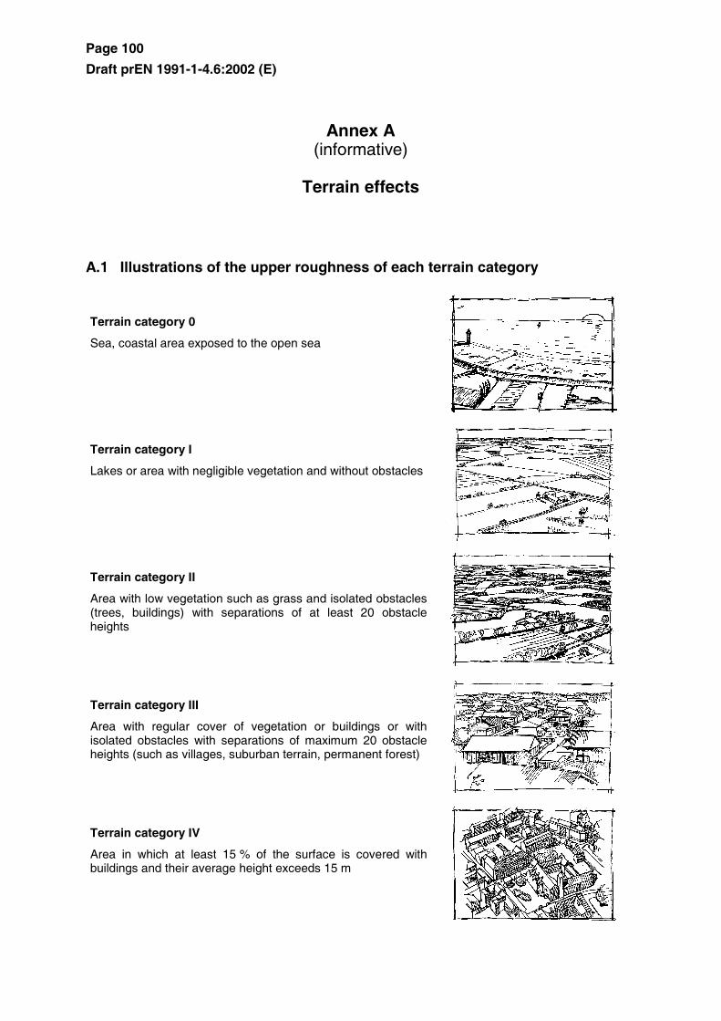
A.1 Illustrations of the upper roughness of each terrain category
Terrain category 0
Sea, coastal area exposed to the open sea
Terrain category I
Lakes or area with negligible vegetation and without obstacles
Terrain category II
Area with low vegetation such as grass and isolated obstacles (trees, buildings) with separations of at least 20 obstacle heights
Terrain category III
Area with regular cover of vegetation or buildings or with isolated obstacles with separations of maximum 20 obstacle heights (such as villages, suburban terrain, permanent forest)
Terrain category IV
Area in which at least 15 % of the surface is covered with buildings and their average height exceeds 15 m
Page 101
Draft prEN 1991-1-4.6:2002 (E)
A.2 Transition between roughness categories 0, I, II, III and IV
(1) The transition between different roughness categories has to be considered when calculating qp and cscd .
NOTE The procedure to be used in a Country may be found in its National Annex. Two recommended procedures, Procedure 1 and Procedure 2, are given below.
Procedure 1
If the structure is situated near a change of terrain roughness at a distance:
– less than 2 km from the smoother category 0 – less than 1 km from the smoother categories I to III the smoother terrain category in the upwind direction should be used
Small areas (less than 10 % of the area under consideration) with deviating roughness can be ignored.
Procedure 2
a) Determine the roughness categories for the upstream terrain in the angular sectors to be considered.
b) For every angular sector, determine the distance x from the building to the upstream roughness changes
c) If the distance x from the building to a terrain with lower roughness length is smaller than the values given in Table A.1, then the lower value for the roughness length should be used for the angular sector considered. If this distance x is larger than the value in Table A.2, the higher value for the roughness length should be used.
Small areas (less than 10 % of the area under consideration) with deviating roughness can be ignored.
Where no distance x is given in Table A.1 or for heights exceeding 50 m, the smaller roughness length should be used.
For intermediate values of height z, linear interpolation may be used.
A building in a certain terrain category may be calculated in a lower terrain category if it is situated within the distance limits defined in Table A.1
Page 102
Draft prEN 1991-1-4.6:2002 (E)
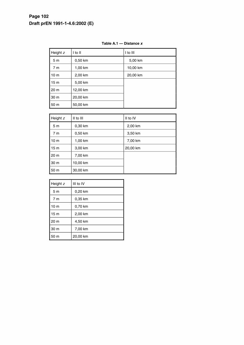
Table A.1 — Distance x
Height z I to II I to III
5 m 0,50 km 5,00 km
7 m 1,00 km 10,00 km
10 m 2,00 km 20,00 km
15 m 5,00 km
20 m 12,00 km
30 m 20,00 km
50 m 50,00 km
Height z II to III II to IV
5 m 0,30 km 2,00 km
7 m 0,50 km 3,50 km
10 m 1,00 km 7,00 km
15 m 3,00 km 20,00 km
20 m 7,00 km
30 m 10,00 km
50 m 30,00 km
Height z III to IV
5 m 0,20 km
7 m 0,35 km
10 m 0,70 km
15 m 2,00 km
20 m 4,50 km
30 m 7,00 km
50 m 20,00 km
Page 103
Draft prEN 1991-1-4.6:2002 (E)
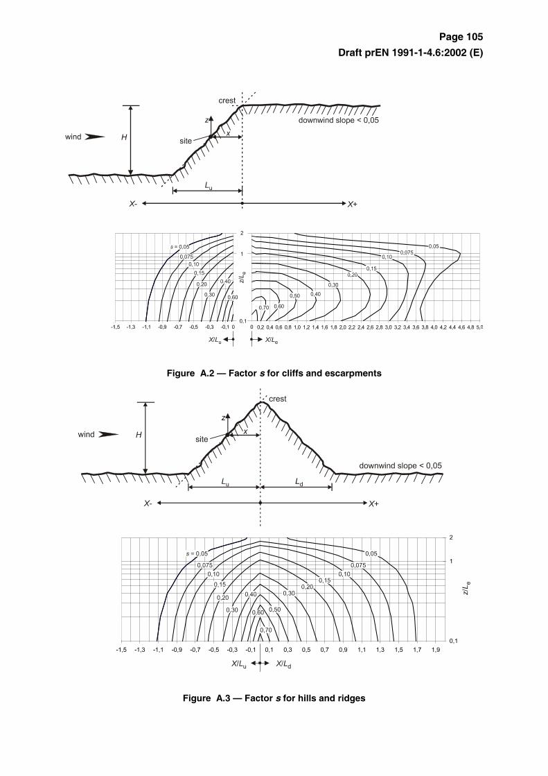
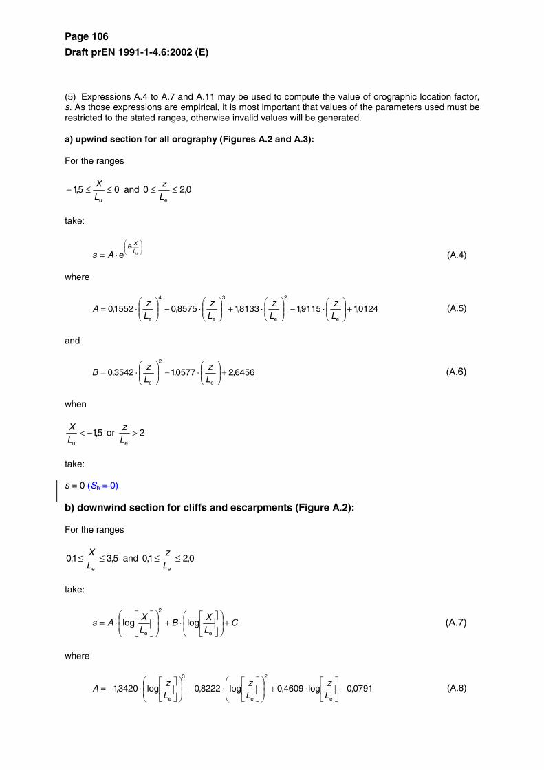
A.3 Numerical calculation of orography coefficients
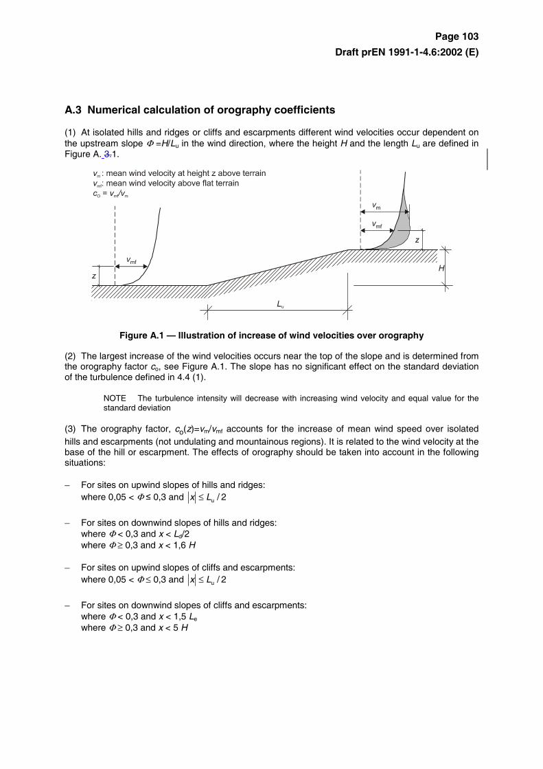
(1) At isolated hills and ridges or cliffs and escarpments different wind velocities occur dependent on the upstream slope Φ =H/Lu in the wind direction, where the height H and the length Lu are defined in Figure A. 3.1.
Figure A.1 — Illustration of increase of wind velocities over orography
(2) The largest increase of the wind velocities occurs near the top of the slope and is determined from the orography factor co, see Figure A.1. The slope has no significant effect on the standard deviation of the turbulence defined in 4.4 (1).
NOTE The turbulence intensity will decrease with increasing wind velocity and equal value for the standard deviation
(3) The orography factor, co(z)=vm/vmf accounts for the increase of mean wind speed over isolated hills and escarpments (not undulating and mountainous regions). It is related to the wind velocity at the base of the hill or escarpment. The effects of orography should be taken into account in the following situations:
– For sites on upwind slopes of hills and ridges: where 0,05 < Φ ≤ 0,3 and 2/uLx ≤
– For sites on downwind slopes of hills and ridges: where Φ < 0,3 and x < Ld/2 where Φ ≥ 0,3 and x < 1,6 H
– For sites on upwind slopes of cliffs and escarpments: where 0,05 < Φ ≤ 0,3 and 2/uLx ≤
– For sites on downwind slopes of cliffs and escarpments: where Φ < 0,3 and x < 1,5 Le
where Φ ≥ 0,3 and x < 5 H
Page 104
Draft prEN 1991-1-4.6:2002 (E)
It is defined by:
co= 1 for Φ < 0,05 (A.1)
co= 1+ 2 · s · Φ for 0,05 < Φ < 0,3 (A.2)
co= 1+ 0,6 · s for Φ > 0,3 (A.3)
where:
s is the orographic location factor, to be obtained from Figure A.2 or Figure A.3 scaled to the length of the effective upwind slope length, Le
Φ is the upwind slope H/Lu in the wind direction (see Figure A.2 and Figure A.3)
Le is the effective length of the upwind slope, defined in Table A.2
Lu is the actual length of the upwind slope in the wind direction
Ld is the actual length of the downwind slope in the wind direction
H is the effective height of the feature
x is the horizontal distance of the site from the top of the crest
z is the vertical distance from the ground level of the site
Table A.2 — Values of the effective length Le. Slope (Φ = H/Lu)
Type of slope (Φ = H/L u)
Shallow (0,05 < Φ < 0,3) Steep (Φ > 0,3)
Le = Lu Le = H/0,3
NOTE The calculated graphs in Figures A.2 and A.3 exceed the area of application as defined above. The consideration of orographic effects beyond these boundaries is optional.
(4) In valleys, co(z) may be set to 1,0 if no speed up due to funnelling effects is to be expected. For structures situated within, or for bridges spanning steep-sided valleys care should be taken to account for any increase of wind speed caused by funnelling.
Page 105
Draft prEN 1991-1-4.6:2002 (E)
Figure A.2 — Factor s for cliffs and escarpments
Figure A.3 — Factor s for hills and ridges
Page 106
Draft prEN 1991-1-4.6:2002 (E)
(5) Expressions A.4 to A.7 and A.11 may be used to compute the value of orographic location factor, s. As those expressions are empirical, it is most important that values of the parameters used must be restricted to the stated ranges, otherwise invalid values will be generated.
a) upwind section for all orography (Figures A.2 and A.3):
For the ranges
05,1u
≤≤−LX
and 0,20e
≤≤Lz
take:
⋅
⋅= ue LX
B
As (A.4)
where
0124,19115,18133,18575,01552,0e
2
e
3
e
4
e
+
⋅−
⋅+
⋅−
⋅=
Lz
Lz
Lz
Lz
A (A.5)
and
6456,20577,13542,0e
2
e
+
⋅−
⋅=
Lz
Lz
B (A.6)
when
5,1u
−<LX
or 2e
>Lz
take:
s = 0 (Sh = 0)
b) downwind section for cliffs and escarpments (Figure A.2):
For the ranges
5,31,0e
≤≤LX
and 0,21,0e
≤≤Lz
take:
CLX
BLX
As +
⋅+
⋅=
e
2
e
loglog (A.7)
where
0791,0log4609,0log8222,0log3420,1e
2
e
3
e
−
⋅+
⋅−
⋅−=
Lz
Lz
Lz
A (A.8)
Page 107
Draft prEN 1991-1-4.6:2002 (E)
1156,0log5343,0log8910,0log0196,1e
2
e
3
e
−
⋅+
⋅−
⋅−=
Lz
Lz
Lz
B (A.9)
and
1606,0log5738,0log4236,0log8030,0e
2
e
3
e
+
⋅−
⋅+
⋅=
Lz
Lz
Lz
C (A.10)
For the range
1,00e
≤≤LX
,
interpolate between values for
0e
=LX
(s = A in Expression A.5) and 1,0e
=LX
.
when: 1,0e
<Lz
use the values for 1,0e
=Lz
.
when: 5,3d
>Lz
or 0,2e
>Lz
take the value s = 0 (Sh = 0)
c) downwind section for hills and ridges (Figure A.3):
For the ranges
0,20d
≤≤LX
and 0,20e
≤≤Lz
take:
⋅
⋅= dLX
B
eAs (A.11)
where:
0124,19115,18133,18575,01552,0e
2
e
3
e
4
e
+
⋅−
⋅+
⋅−
⋅=
Lz
Lz
Lz
Lz
A (A.12)
and
7637,10212,13056,0e
2
e
−
⋅+
⋅−=
Lz
Lz
B (A.13)
Page 108
Draft prEN 1991-1-4.6:2002 (E)
NOTE Expressions A.5 and A.12 are identical.
when
0,2d
>LX
or 0,2e
>Lz
take:
s = 0 (Sh = 0)
NOTE Expressions A.5 and A.12 are identical.
A.4 Neighbouring structures
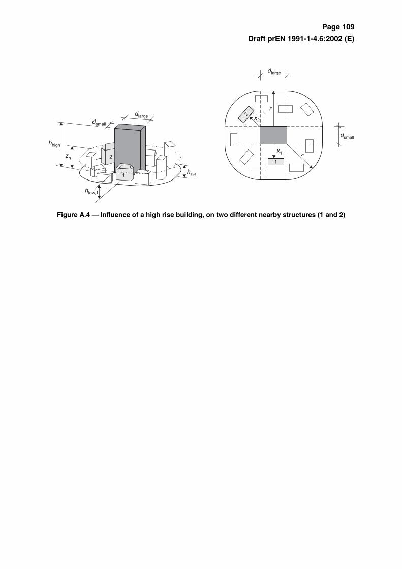
(1) If a building is more than twice as high as the average height have of the neighbouring structures then, as a first approximation, the design of any of those nearby structures may be based on the peak velocity pressure at height zn (ze = zn) above ground (Expression A.14), see Figure A.4.
rx ≤ : rz ⋅=21
n
rxr ⋅<< 2 :
−⋅⋅
−−= )()2
1(21 low
n rxr
hrz (A.14)
rx ⋅≥ 2 : lown hz =
in which the radius r is:
r = hhigh if hhigh ≤ 2 ⋅ dlarge
r = 2 ⋅ dlarge if hhigh > 2 ⋅ dlarge
The structural height hlow, the radius r, the distance x and the dimensions dsmall and dlarge are illustrated in Figure A.4 Increased wind velocities can be disregarded when hlow is more than half the height hhigh of the high building, i.e. zn = hlow.
Page 109
Draft prEN 1991-1-4.6:2002 (E)
Figure A.4 — Influence of a high rise building, on two different nearby structures (1 and 2)
Page 110
Draft prEN 1991-1-4.6:2002 (E)
A.5 Displacement height
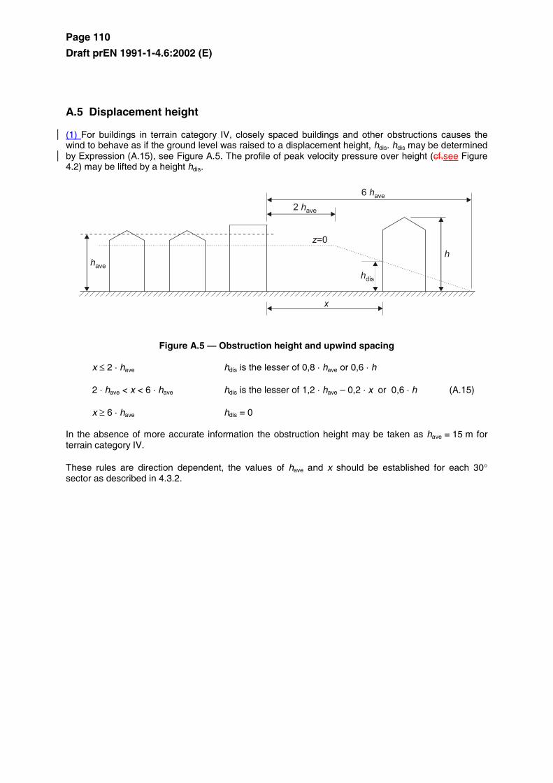
(1) For buildings in terrain category IV, closely spaced buildings and other obstructions causes the wind to behave as if the ground level was raised to a displacement height, hdis. hdis may be determined by Expression (A.15), see Figure A.5. The profile of peak velocity pressure over height (cf.see Figure 4.2) may be lifted by a height hdis.
Figure A.5 — Obstruction height and upwind spacing
x ≤ 2 ⋅ have hdis is the lesser of 0,8 ⋅ have or 0,6 ⋅ h
2 ⋅ have < x < 6 ⋅ have hdis is the lesser of 1,2 ⋅ have – 0,2 ⋅ x or 0,6 ⋅ h (A.15)
x ≥ 6 ⋅ have hdis = 0
In the absence of more accurate information the obstruction height may be taken as have = 15 m for terrain category IV.
These rules are direction dependent, the values of have and x should be established for each 30° sector as described in 4.3.2.

![[ger] Eisen und Stahl : 2 1991 Monatlich [eng] Iron and ...aei.pitt.edu/72441/1/1991.2.pdf · En janvier 1991, la production communautaire d'acier brut a enregistré, avec 11,3 mio.t,](https://static.fdocument.org/doc/165x107/5e6c265a64902218da4d23f6/ger-eisen-und-stahl-2-1991-monatlich-eng-iron-and-aeipittedu72441119912pdf.jpg)


![Icosidodecahedron 4[1]](https://static.fdocument.org/doc/165x107/55156c554979591d538b48e3/icosidodecahedron-41.jpg)