Muons for a Neutrino Factory and a Muon Collider · Muon Requirements • ≈ 1014 μ±/s for...
26
Muons for a Neutrino Factory and a Muon Collider Kirk T. McDonald Princeton U. [email protected] ν Fact’99, Lyon, France July 6, 1999 Muon Collider main page: http://www.cap.bnl.gov/mumu/mu home page.html Muon Collider R&D Status Report: http://www.cap.bnl.gov/mumu/status report.html Muon Collider Targetry page: http://puhep1.princeton.edu/mumu/target/ 1
Transcript of Muons for a Neutrino Factory and a Muon Collider · Muon Requirements • ≈ 1014 μ±/s for...
Muons for a Neutrino Factory
and a Muon Collider
Kirk T. McDonald
Princeton U.
νFact’99, Lyon, France
July 6, 1999
Muon Collider main page:
http://www.cap.bnl.gov/mumu/mu home page.html
Muon Collider R&D Status Report:
http://www.cap.bnl.gov/mumu/status report.html
Muon Collider Targetry page:
http://puhep1.princeton.edu/mumu/target/
1
Muon Requirements
• ≈ 1014 μ±/s for either a muon collider or a neutrino factory.
• The muons come from the decay of soft pions produced in
p-nucleus collisions.
• Our strategy is to maximize the ratio of captured
muons per proton.
i.e., to minimize the proton requirements.
• Goal: 0.1μ/p delivered for physics use.
2
The Muon Source
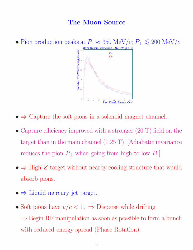
• Pion production peaks at P‖ ≈ 350 MeV/c; P⊥ <∼ 200 MeV/c.Mars Meson Production - 16 GeV p + W
0
0.5
1
1.5
2
2.5
0 0.2 0.4 0.6 0.8 1 1.2 1.4 1.6 1.8
Pion Kinetic Energy, GeV
dN/d
KE
(1/
GeV
/int
erac
ting
pro
ton) π−
π+
• ⇒ Capture the soft pions in a solenoid magnet channel.
• Capture efficiency improved with a stronger (20 T) field on the
target than in the main channel (1.25 T). [Adiabatic invariance
reduces the pion P⊥ when going from high to low B.]
• ⇒ High-Z target without nearby cooling structure that would
absorb pions.
• ⇒ Liquid mercury jet target.
• Soft pions have v/c < 1, ⇒ Disperse while drifting
⇒ Begin RF manipulation as soon as possible to form a bunch
with reduced energy spread (Phase Rotation).
3

Overview of Targetry for a Muon Collider
• 1.2 × 10¹⁴ μ±/s via π-decay from a 4-MW proton beam.
• Proton pulse ≈ 1 ns rms for a muon collider.
• Mercury jet target.
• 20-T capture solenoid followed by a 1.25-T π-decay channel
with phase-rotation via rf (to compress energy of the muon
bunch).
4
Targetry Issues
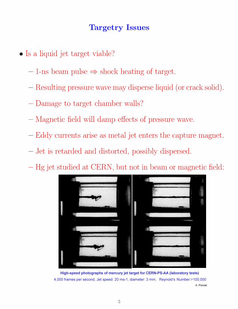
• Is a liquid jet target viable?
– 1-ns beam pulse ⇒ shock heating of target.
– Resulting pressure wave may disperse liquid (or crack solid).
– Damage to target chamber walls?
– Magnetic field will damp effects of pressure wave.
– Eddy currents arise as metal jet enters the capture magnet.
– Jet is retarded and distorted, possibly dispersed.
– Hg jet studied at CERN, but not in beam or magnetic field:
����������� ������������������� � ��� ����������������������� ���� � �
��������������� �������������������������������� �������������� �������
!"�#�� �
5
• Is the first rf cavity viable?
– High-gradient (5 MeV/m), low-frequency (≈ 70 MHz) rf
cavity only 3 m downstream of target.
– > 1014 particles traverse the cavity each proton pulse; many
hit the cavity wall.
– Cavities tested against breakdown from beam-induced
showers only up to ≈ 1012 particles/pulse.
• Is the 20-T Solenoid viable?
– Even with water-cooled tungsten inserts, this hybrid
(copper/superconductor) magnet will experience a very high
radiation dose.
– LANL has experience with superconducting magnets in high
radiation areas.
• Other Radiological Issues
– A 4-MW beam leads to activation issues characteristic of
neutron spallation sources.
– Remote handling of activated liquid target material is under
study at CERN ISOLDE, the ORNL NSNS, ...
6
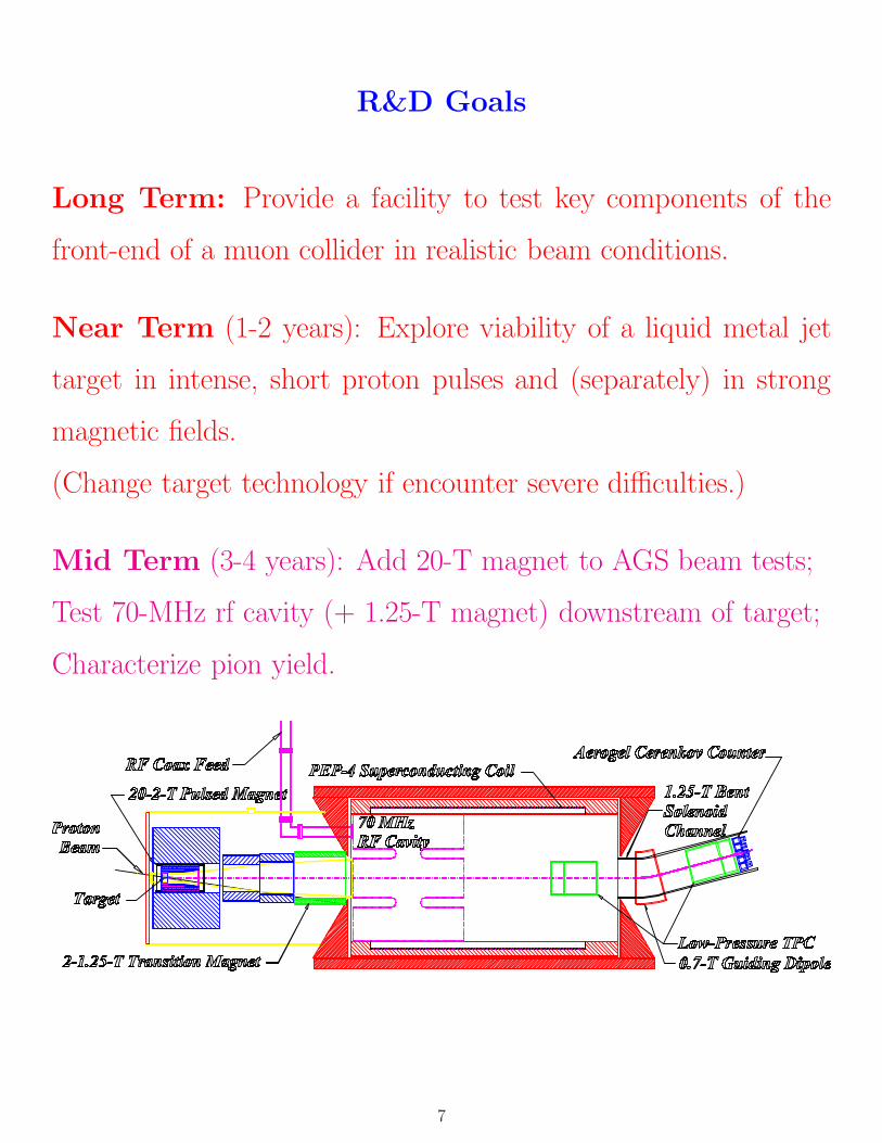
R&D Goals
Long Term: Provide a facility to test key components of the
front-end of a muon collider in realistic beam conditions.
Near Term (1-2 years): Explore viability of a liquid metal jet
target in intense, short proton pulses and (separately) in strong
magnetic fields.
(Change target technology if encounter severe difficulties.)
Mid Term (3-4 years): Add 20-T magnet to AGS beam tests;
Test 70-MHz rf cavity (+ 1.25-T magnet) downstream of target;
Characterize pion yield.
7

An R&D Program for Targetry and Capture
at a Muon Collider Source
A Proposal to the BNL AGS Division (P951)
James Alessi,b John Corlett,e D. Duncan Earl,f Richard C. Fernow,b Yasuo Fukui,e
Tony A. Gabriel,f Juan C. Gallardo,b Michael A. Green,e John R. Haines,f Jerry
Hastings,b Ahmed Hassanein,a Colin Johnson,c Stephen A. Kahn,b Bruce J. King,b
Harold G. Kirk,b Paul Lebrun,d Vincent LoDestro,b Changguo Lu,g
Kirk T. McDonald,g,1 Nikolai V. Mokhov,d Alfred Morettid, James H. Norem,a
Robert B. Palmer,b Eric J. Prebys,g Claude Reed,a Thomas Roser,b
Ronald M. Scanlan,e Dale L. Smith,a Yagmur Torun,b,h Andy van Ginneken,d
Haipeng Wang,b Robert Weggel,b Yongxiang Zhaob
aArgonne National Laboratory, Argonne, IL 60439bBrookhaven National Laboratory, Upton, NY 11973
cCERN, 1211 Geneva 23, SwitzerlanddFermi National Laboratory, P. O. Box 500, Batavia, IL 60510
eLawrence Berkeley National Laboratory, 1 Cyclotron Rd., Berkeley, CA 94720fOak Ridge National Laboratory, Oak Ridge, TN 37831
gJoseph Henry Laboratories, Princeton University, Princeton, NJ 08544hDepartment of Physics and Astronomy, SUNY, Stony Brook, NY 11790
(Submitted Sept. 28, 1998)
1Spokesperson. Email: [email protected]
8
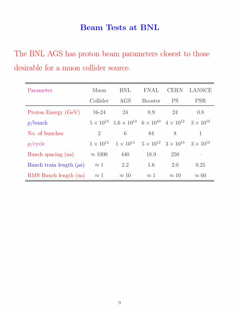
Beam Tests at BNL
The BNL AGS has proton beam parameters closest to those
desirable for a muon collider source.
Parameter Muon BNL FNAL CERN LANSCE
Collider AGS Booster PS PSR
Proton Energy (GeV) 16-24 24 8.9 24 0.8
p/bunch 5 × 10¹³ 1.6 × 10¹³ 6 × 10¹⁰ 4 × 10¹² 3 × 10¹³
No. of bunches 2 6 84 8 1
p/cycle 1 × 10¹⁴ 1 × 10¹⁴ 5 × 10¹² 3 × 10¹³ 3 × 10¹³
Bunch spacing (ns) ≈ 1000 440 18.9 250 –
Bunch train length (μs) ≈ 1 2.2 1.6 2.0 0.25
RMS Bunch length (ns) ≈ 1 ≈ 10 ≈ 1 ≈ 10 ≈ 60
9
The 8 Steps in the R&D Program
1. Simple tests of liquid (Ga-Sn, Hg) and solid (Ni) targets with
AGS Fast Extracted Beam (FEB).
2. Test of liquid jet entering a 20-T magnet (20-MW cw Bitter
magnet at the National High Magnetic Field Laboratory).
3. Test of liquid jet with 1014 ppp via full turn FEB (without
magnet).
4. Add 20-T pulsed magnet (4-MW peak) to liquid jet test with
AGS FEB.
5. Add 70-MHz rf cavity downstream of target in FEB.
6. Surround rf cavity with 1.25-T magnet. At this step we have
all essential features of the source.
7. Characterize pion yield from target + magnet system with slow
extracted beam (SEB).
8. Ongoing simulation of the thermal hydraulics of the liquid-
metal target system.
10
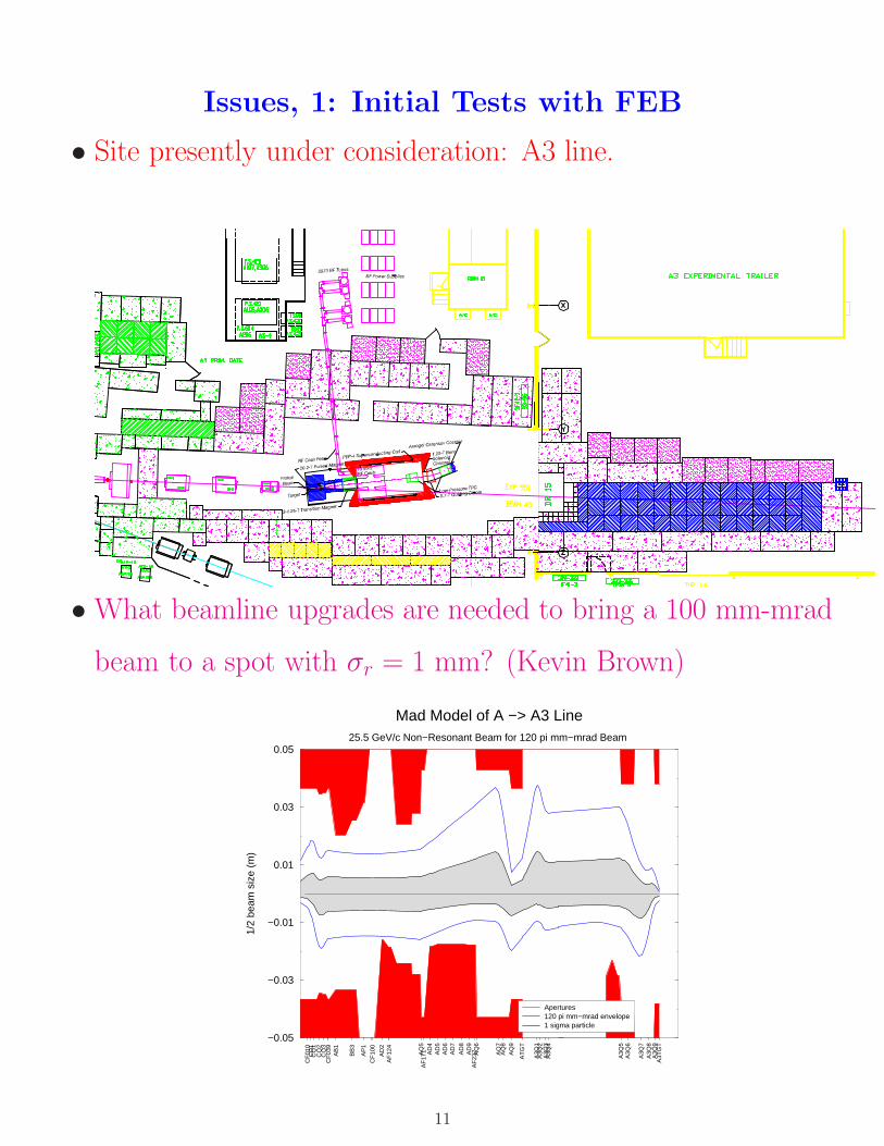
Issues, 1: Initial Tests with FEB
• Site presently under consideration: A3 line.
• What beamline upgrades are needed to bring a 100 mm-mrad
beam to a spot with σr = 1 mm? (Kevin Brown)
CF
010
CD
1 C
Q1
CQ
2 C
Q3
CF
039
AB
1
BB
3
AP
1 C
F10
0
AD
2 A
F12
4
AQ
5A
F17
1
AD
4A
D5
AD
6A
D7
AD
8A
D9
AF
237
A
Q6
AQ
7A
Q8
AQ
9
AT
GT
A3Q
1A
3Q2
A3Q
3A
3Q4
A3Q
5A
3Q6
A3Q
7A
3Q8
A3Q
9A
3TG
T
−0.05
−0.03
−0.01
0.01
0.03
0.05
1/2
beam
siz
e (m
)
Mad Model of A −> A3 Line25.5 GeV/c Non−Resonant Beam for 120 pi mm−mrad Beam
Apertures120 pi mm−mrad envelope1 sigma particle
11
• Beamline instrumentation upgrades: spot size, beam current,
FEB radiation monitoring.
• Run first tests parasitic to g − 2 expt. in Mar/Apr 2000.
• Data taking via pulse-on-demand once every few minutes; but
desire 1-Hz running for beam tuning.
• Shielding needed for 1-Hz running with 1014 ppp = 100 TP
(Ripp Bowman, Ralf Prigl).
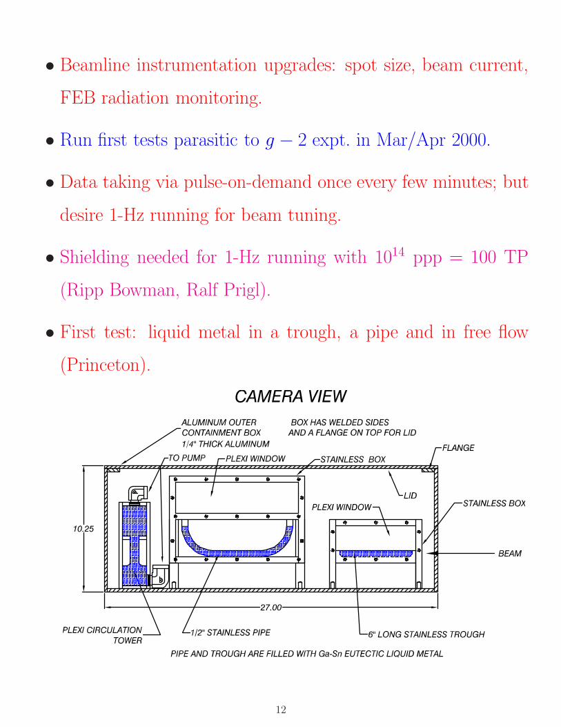
• First test: liquid metal in a trough, a pipe and in free flow
(Princeton).
12
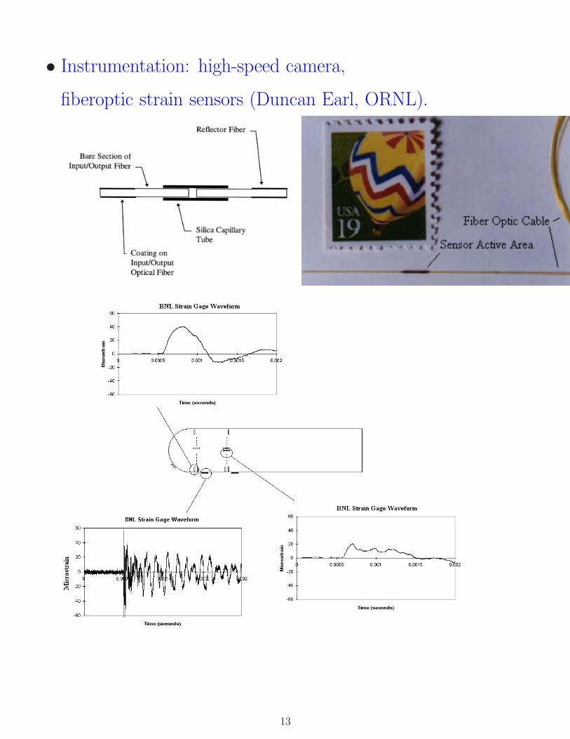
• Instrumentation: high-speed camera,
fiberoptic strain sensors (Duncan Earl, ORNL).
13
Issues, 2: Pulsed Liquid Jet
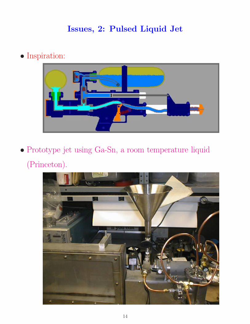
• Inspiration:
• Prototype jet using Ga-Sn, a room temperature liquid
(Princeton).
14

• May 18, 1999: Ga-Sn jet breaks up too quickly, forms oxide
scum:
• Hg jet under construction at CERN (Colin Johnson, Helge
Ravn), and at Princeton.
15
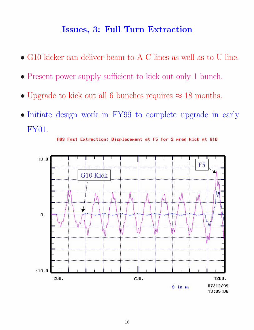
Issues, 3: Full Turn Extraction
• G10 kicker can deliver beam to A-C lines as well as to U line.
• Present power supply sufficient to kick out only 1 bunch.
• Upgrade to kick out all 6 bunches requires ≈ 18 months.
• Initiate design work in FY99 to complete upgrade in early
FY01.
16
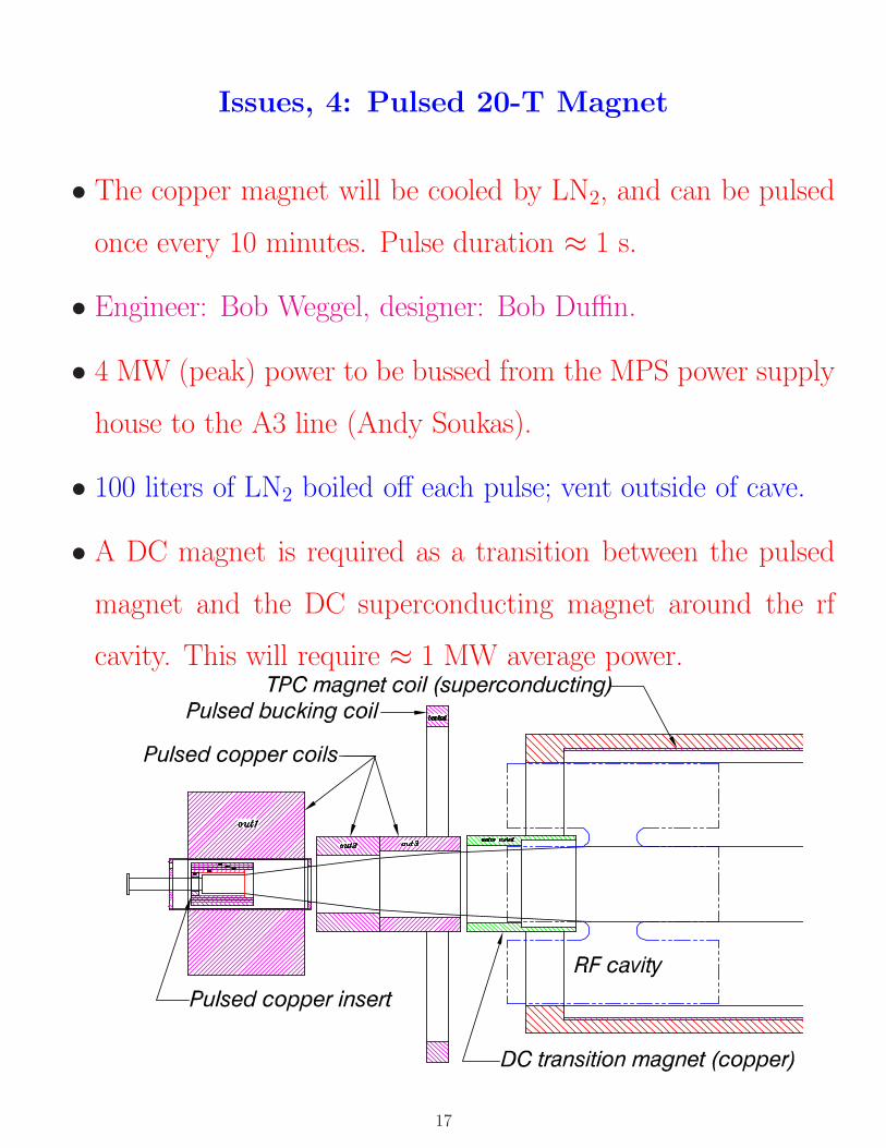
Issues, 4: Pulsed 20-T Magnet
• The copper magnet will be cooled by LN2, and can be pulsed
once every 10 minutes. Pulse duration ≈ 1 s.
• Engineer: Bob Weggel, designer: Bob Duffin.
• 4 MW (peak) power to be bussed from the MPS power supply
house to the A3 line (Andy Soukas).
• 100 liters of LN2 boiled off each pulse; vent outside of cave.
• A DC magnet is required as a transition between the pulsed
magnet and the DC superconducting magnet around the rf
cavity. This will require ≈ 1 MW average power.
17
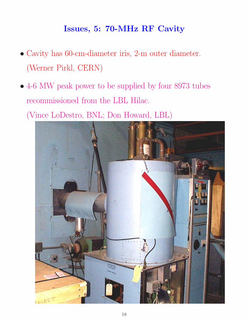
Issues, 5: 70-MHz RF Cavity
• Cavity has 60-cm-diameter iris, 2-m outer diameter.
(Werner Pirkl, CERN)
• 4-6 MW peak power to be supplied by four 8973 tubes
recommissioned from the LBL Hilac.
(Vince LoDestro, BNL; Don Howard, LBL)
18
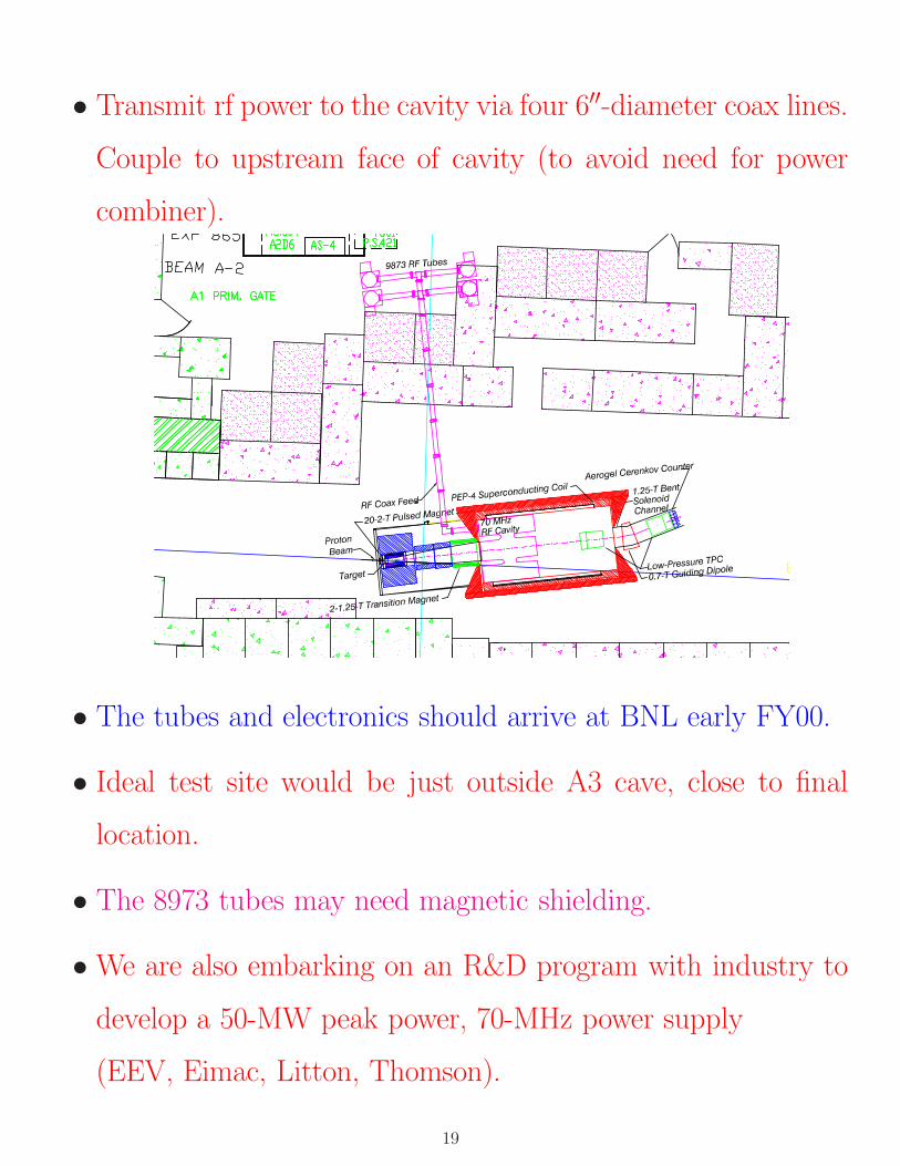
• Transmit rf power to the cavity via four 6′′-diameter coax lines.
Couple to upstream face of cavity (to avoid need for power
combiner).
• The tubes and electronics should arrive at BNL early FY00.
• Ideal test site would be just outside A3 cave, close to final
location.
• The 8973 tubes may need magnetic shielding.
• We are also embarking on an R&D program with industry to
develop a 50-MW peak power, 70-MHz power supply
(EEV, Eimac, Litton, Thomson).
19
Issues, 6: 1.25-T Solenoid Around RF Cavity
• Present plan: use PEP-4 TPC superconducting solenoid
(Mike Green, LBL).
• Use 100-W LHe refrigerator from E-850.
• Need DC transition magnet to protect the superconducting
magnet from quenching during pulsing of the 20-T magnet
(Bob Weggel).
• Need end plate steel and/or bucking coils to complete the
isolation of the superconducting magnet.
• The magnet fringe fields will extend a considerable distance.
20
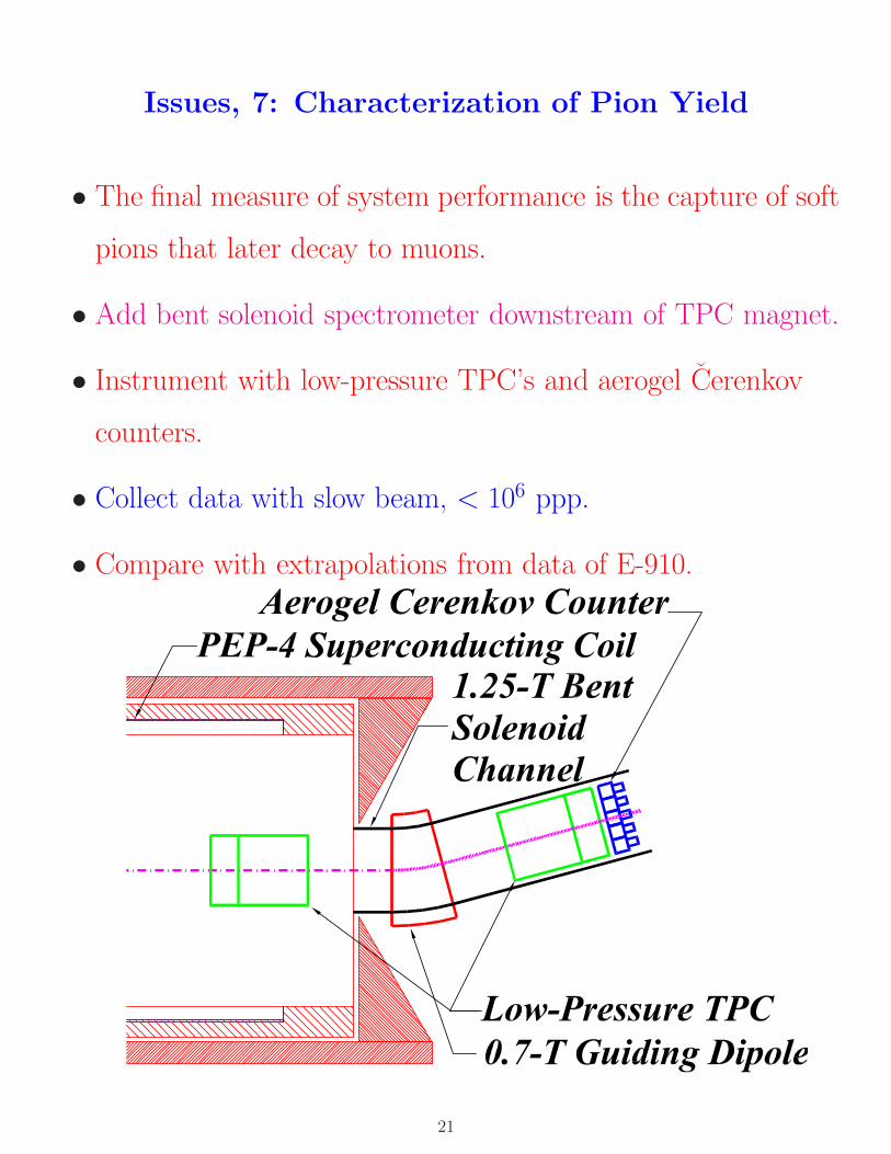
Issues, 7: Characterization of Pion Yield
• The final measure of system performance is the capture of soft
pions that later decay to muons.
• Add bent solenoid spectrometer downstream of TPC magnet.
• Instrument with low-pressure TPC’s and aerogel Cerenkov
counters.
• Collect data with slow beam, < 106 ppp.
• Compare with extrapolations from data of E-910.
21
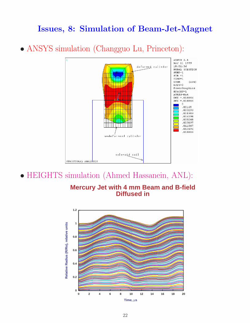
Issues, 8: Simulation of Beam-Jet-Magnet
• ANSYS simulation (Changguo Lu, Princeton):
• HEIGHTS simulation (Ahmed Hassanein, ANL):
0
0.2
0.4
0.6
0.8
1
1.2
0 2 4 6 8 10 12 14 16 18 20
Rel
ativ
e R
adiu
s (R
/Ro
), r
elat
ive
un
its
Time, μs
Mercury Jet with 4 mm Beam and B-fieldDiffused in
22
Pressure and Temperature Profiles
23
Effect of a Scaled-Down Target
24
Schedule
• FY99:
Prepare A3 area; begin work on liquid jets, extraction upgrade,
magnet systems, and rf systems.
• FY00:
Initial beam tests in A3 line. Liquid jet test at NHMFL.
(600 hours of AGS beamtime).
• FY01:
Complete extraction upgrade; test of liquid jet + beam.
(600 hours).
• FY02:
Complete magnet and rf systems; test with 2 ns beam.
(600 hours).
• FY03:
Complete pion detectors; test with low intensity SEB.
(600 hours).
25
AGS Operations Issues
• In FY00/01, HEP operation of AGS is only for the g − 2
experiment, with fast extraction. P951 is very compatible with
parasitic running in this condition.
• After FY01, no DOE approved HEP operation of the AGS.
• The AGS2000 program proposes running slow extracted proton
beam 30-35 weeks/yr, for 16-20 hours/day during RHIC
operation.
• P951 requires fast extracted beam, so cannot parasite off the
AGS2000 program; we must interleave running with AGS2000,
but seek <∼ 6 weeks/yr.
• If there is no other HEP operation of the AGS after FY01, P951
would then bear the full incremental cost of proton beam
running.
26


![Study of multi-muon events at CDFCMUP muons (trigger muons) and pass all analysis cuts. Use a heavy flavor simulation [HERWIG]. • Probability per track that a hadron yields a trigger](https://static.fdocument.org/doc/165x107/5e6e6d17497c955e242212c7/study-of-multi-muon-events-at-cdf-cmup-muons-trigger-muons-and-pass-all-analysis.jpg)