MULTIS L40 - AsiaSafeConnection.comasiasafeconnection.com/FileUpload/Editor/Documents... · • The...
2
Metering, monitoring & power quality multi_055_a_1_cat MULTIS L40 Measurement devices 96 x 96 - Three phases - All electrical parameters measurement Function The SOCOMEC MULTIS range 96 x 96 insure the measurement of all your electrical parameters, V, A, Hz, P, Q, S, COS ϕ… For Single and Three phases network. Applications • The MULTIS L40 is a digital three phase multimeter for measuring electrical values in LV and HV networks. In addition to the MULTIS L20 functions the MULTIS L40 also offers MODBUS RTU communication via RS485, measurement of the energies (active, reactive) and pulse output. ■ Multi-meter MULTIS L40 Electrical characteristics Measurements AC network LV or HV, three phase + neutral Measurement range Secondary 0.05…5.5 A Primary 5/5 A ... 10000/5 A Primary 1/1 A ... 2000/1 A Secondary 10…300 VAC Primary 10 V…200 kVAC Measurement range between phases 10 … 500 VAC Accuracy 1 % ± 1 digit Auxiliary power supply Voltage 190 … 260 VAC Frequency 45 … 65 Hz Consumption < 4 VA Operating conditions Operating temperature -5 … +50 °C Communication Type MODBUS RTU via RS485 Pulse output Weight 1 Wh … 1 MWh / 1 VArh … 1 MVArh Operation current 50 mA max. Operation voltage 5 … 24 VDC ; 30 VDC max. Pulse duration 100 ms max. Case Type panel mounting Dimensions W x H x D 96 x 96 x 82 mm Panel cut out dimensions (H x W) 91 x 91 mm Front protection rating IP40 Weight 0.45 kg 12mm Input Operation voltage 12 … 48 VAC / DC
Transcript of MULTIS L40 - AsiaSafeConnection.comasiasafeconnection.com/FileUpload/Editor/Documents... · • The...
Met
erin
g, m
oni
tori
ng
& p
ow
er q
ualit
y
mul
ti_05
5_a_
1_ca
t
MULTIS L40Measurement devices96 x 96 - Three phases - All electrical parameters measurement
FunctionThe SOCOMEC MULTIS range 96 x 96 insure the measurement of all your electrical parameters, V, A, Hz, P, Q, S, COS ϕ… For Single and Three phases network.
Applications • The MULTIS L40 is a digital three phase multimeter for measuring electrical values in LV and HV networks. In addition to the MULTIS L20 functions the MULTIS L40
also offers MODBUS RTU communication via RS485, measurement of the energies (active, reactive) and pulse output.
Multi-meter MULTIS L40
Electrical characteristics
Measurements
AC network LV or HV, three phase + neutral
Measurement range
Secondary 0.05…5.5 APrimary 5/5 A ... 10000/5 APrimary 1/1 A ... 2000/1 ASecondary 10…300 VACPrimary 10 V…200 kVAC
Measurement range between phases 10 … 500 VAC
Accuracy 1 % ± 1 digit Auxiliary power supply
Voltage 190 … 260 VAC
Frequency 45 … 65 Hz
Consumption < 4 VA
Operating conditions
Operating temperature -5 … +50 °C
Communication
Type MODBUS RTU via RS485
Pulse output
Weight 1 Wh … 1 MWh / 1 VArh … 1 MVArh
Operation current 50 mA max.
Operation voltage 5 … 24 VDC ; 30 VDC max.
Pulse duration 100 ms max.
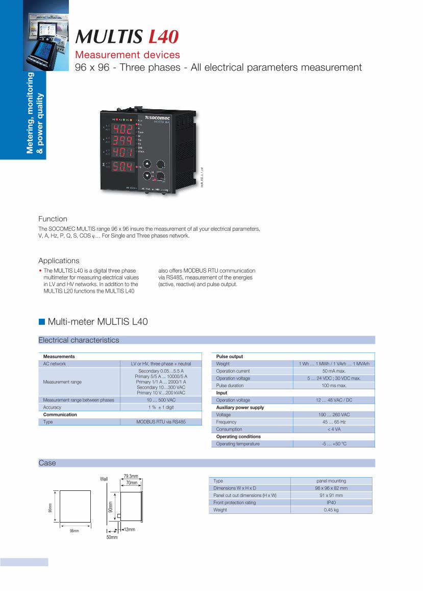
Case
Type panel mounting
Dimensions W x H x D 96 x 96 x 82 mm
Panel cut out dimensions (H x W) 91 x 91 mm
Front protection rating IP40
Weight 0.45 kg
Dimensions
Panel Cut-out
Preset Single Register (06) function is used for writting the setting values, erasing the energy counter or resetting the min., max., demand values. Current transformers ratio can be set 0-2000, voltage transformer ratio can be set 1-40000. Min., Max. and Demand values can be only clear. If sent value is outside of this range device responds with an error message.
Example. Setting CT as 100;01 06 80 02 00 64 XX XX
01 Device address06 Function80 MSB address02 LSB address00 Data MSB64 Data LSBXX CRC MSBXX CRC LSB
Preset Multiple Register (10H) is used to set more then one register at same time.
Example. Setting CT as 100, Ut as 20.0;01 10 80 00 00 02 04 00 C8 00 64 XX XX
01 Device Address10 Function80 MSB address00 LSB address00 Register number MSB02 Register number LSB04 Byte count00 Data MSBC8 Data LSB00 Data MSB64 Data LSBXX CRC MSBXX CRC LSB
Digital InputsDigital input are sent in 16 bit hexadecimal format as below:
U U U U U U U U U U U U U U DIN2 DIN1
If 12-48 V AC / DC is applied to ln1 (Input 1), 0 (zero) bit of DIN register is set as “1”. Otherwise, 0 (zero) bit is set as “0”.If 12-48 V AC / DC is applied to ln2 (Input 2), 1st bit of DIN register is set as “1”. Otherwise, 1st bit is set as “0”.
The Parameters are sent in 32 bit Hexadecimal format. For Example, 230.0V voltage will be sent as 000008FCH. Cosphi values shall be divided to 1000.
0.980 Cosphi will be sent as 000003D4H. Energy values are sent in 64 bytes.1234567890123456789 Wh = AB 54 A9 8C EB 1F 0A D2 Wh
Specifications for data cable; 24 AWG or thicker Less than 100 ohm/ km Nominal characteristic impedance at 100 kHz of 120 ohms Less than 60 pF/m mutual capacitance (between two wires in a pair) Less than 120 pF/m mutual pair capacitance ( the capacitance between one wire and all others connected to earth). Twisted Pair
Error codesslave device (MULTIS L40) sends error message when receive any missing query.Error codes are given below.01 Invalid Function: If any message except given above is used, then 01 error messages will be sent.02 Invalid Register: Error 02 will be send when a reading of a register is requested, except the registers which mentioned in table.03 Invalid data: If any different value is been set for dedicated Transformer values and nonzero for demand value, then error message 03 will be sent.
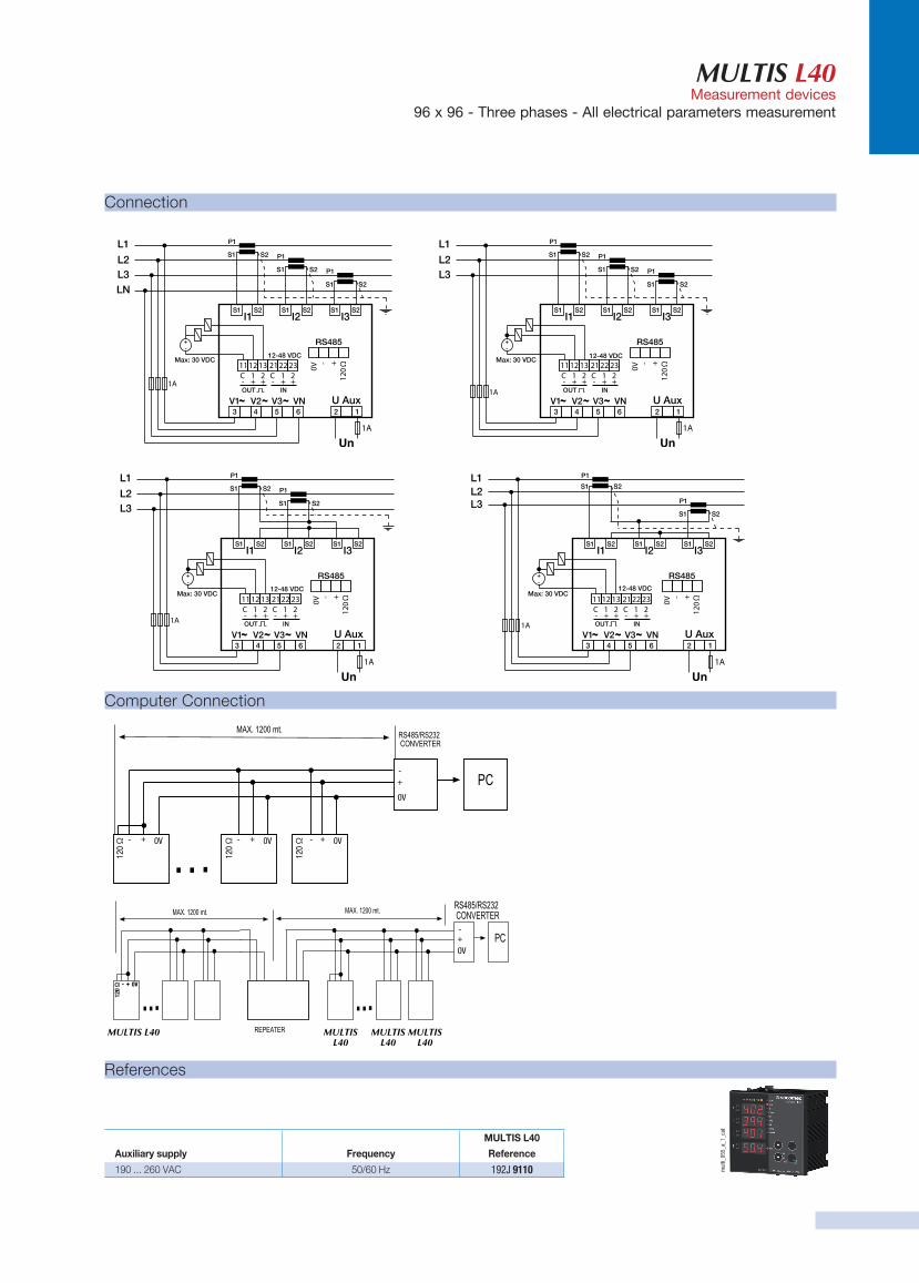
MULTIS L40 computer connection31 Devices can be connected at the same lineMax. 247 Devices can be connected at same line by using repeater.
input 111555H 0
input 2LSB
(Least Significant Byte)MSB
(Most Significant Byte)U: undefined
120
Ω12
0 Ω - + 0V
120
Ω
120
Ω- - -
-
-
+ + +
+
+
0V 0V 0V
0V
0V
MULTIS L40 MULTIS L40
MULTIS L40
MULTIS L40
12mm
540546b.indd 4 20/03/12 20:18
Input
Operation voltage 12 … 48 VAC / DC
MULTIS L40Measurement devices
96 x 96 - Three phases - All electrical parameters measurement
Connection
12-48 VDC
1A
S1
P1L1
L2L3LN
Max: 30 VDC
S2
S1
P1
S2
S1
P1
S2
U AuxV1 V3V2 VN126
111213 212223
543
I2I1 I3
C-
1+
OUT IN
2+
C-
1+
2+
RS485
0V
120
Ω+ -
S1 S2 S1 S2 S1 S2
1A
1A
S1
P1
Max: 30 VDC12-48 VDC
S2
S1
P1
S2
S1
P1
S2
U AuxV1 V3V2 VN126
111213 212223
543
I2I1 I3
C-
1+
OUT IN
2+
C-
1+
2+
RS485
0V
120
Ω+ -
S1 S2 S1 S2 S1 S2
L1
L2L3
1A
12-48 VDC
1A
S1
P1
Max: 30 VDC
S2
S1
P1
S2
U AuxV1 V3V2 VN126
111213 212223
543
I2I1 I3
C-
1+
OUT IN
2+
C-
1+
2+
RS485
0V
120
Ω+ -
S1 S2 S1 S2 S1 S2
L1
L2L3
1A
12-48 VDC
1A
S1
P1
Max: 30 VDC
S2
S1
P1
S2
U AuxV1 V3V2 VN126
111213 212223
543
I2I1 I3
C-
1+
OUT IN
2+
C-
1+
2+
RS485
0V
120
Ω+ -
S1 S2 S1 S2 S1 S2
L1L2L3
1A
12-48 VDC
1A
S1
P1L1
L2L3LN
Max: 30 VDC
S2
S1
P1
S2
S1
P1
S2
U AuxV1 V3V2 VN126
111213 212223
543
I2I1 I3
C-
1+
OUT IN
2+
C-
1+
2+
RS485
0V
120
Ω+ -
S1 S2 S1 S2 S1 S2
1A
1A
S1
P1
Max: 30 VDC12-48 VDC
S2
S1
P1
S2
S1
P1
S2
U AuxV1 V3V2 VN126
111213 212223
543
I2I1 I3
C-
1+
OUT IN
2+
C-
1+
2+
RS485
0V
120
Ω+ -
S1 S2 S1 S2 S1 S2
L1
L2L3
1A
12-48 VDC
1A
S1
P1
Max: 30 VDC
S2
S1
P1
S2
U AuxV1 V3V2 VN126
111213 212223
543
I2I1 I3
C-
1+
OUT IN
2+
C-
1+
2+
RS485
0V
120
Ω+ -
S1 S2 S1 S2 S1 S2
L1
L2L3
1A
12-48 VDC
1A
S1
P1
Max: 30 VDC
S2
S1
P1
S2
U AuxV1 V3V2 VN126
111213 212223
543
I2I1 I3
C-
1+
OUT IN
2+
C-
1+
2+
RS485
0V
120
Ω+ -
S1 S2 S1 S2 S1 S2
L1L2L3
1A
References
MULTIS L40
Auxiliary supply Frequency Reference
190 ... 260 VAC 50/60 Hz 192J 9110 mul
ti_05
5_a_
1_ca
t
Computer Connection
120 Ω
120 Ω - + 0V
120 Ω
120 Ω- - -
-
-
+ + +
+
+
0V 0V 0V
0V
0V
MULTIS L40 MULTIS L40
MULTIS L40
MULTIS L40