MS5611-01BA03 Barometric Pressure Sensor, with stainless ... · PDF fileMS5611-01BA03...
20
MS5611-01BA03 Barometric Pressure Sensor, with stainless steel cap DA5611-01BA03_011 www.meas-spec.com Oct. 26, 2012 000056111624 ECN1742 1/20 • High resolution module, 10 cm • Fast conversion down to 1 ms • Low power, 1 μA (standby < 0.15 μA) • QFN package 5.0 x 3.0 x 1.0 mm 3 • Supply voltage 1.8 to 3.6 V • Integrated digital pressure sensor (24 bit ΔΣ ADC) • Operating range: 10 to 1200 mbar, -40 to +85 °C • I 2 C and SPI interface up to 20 MHz • No external components (Internal oscillator) • Excellent long term stability DESCRIPTION The MS5611-01BA is a new generation of high resolution altimeter sensors from MEAS Switzerland with SPI and I 2 C bus interface. This barometric pressure sensor is optimized for altimeters and variometers with an altitude resolution of 10 cm. The sensor module includes a high linearity pressure sensor and an ultra low power 24 bit ΔΣ ADC with internal factory calibrated coefficients. It provides a precise digital 24 Bit pressure and temperature value and different operation modes that allow the user to optimize for conversion speed and current consumption. A high resolution temperature output allows the implementation of an altimeter/thermometer function without any additional sensor. The MS5611-01BA can be interfaced to virtually any microcontroller. The communication protocol is simple, without the need of programming internal registers in the device. Small dimensions of only 5.0 mm x 3.0 mm and a height of only 1.0 mm allow for integration in mobile devices. This new sensor module generation is based on leading MEMS technology and latest benefits from MEAS Switzerland proven experience and know-how in high volume manufacturing of altimeter modules, which have been widely used for over a decade. The sensing principle employed leads to very low hysteresis and high stability of both pressure and temperature signal. FEATURES FIELD OF APPLICATION TECHNICAL DATA • Mobile altimeter / barometer systems Sensor Performances (VDD = 3 V) • Bike computers Pressure Min Typ Max Unit • Variometers Range 10 1200 mbar • Height sensing for medical alarms ADC 24 bit • Indoor navigation Resolution (1) 0.065 / 0.042 / 0.027 / 0.018 / 0.012 mbar FUNCTIONAL BLOCK DIAGRAM VDD GND PS SCLK SDO SDI/SDA Meas. MUX ADC Digital Interface Memory (PROM) 128 bits SENSOR SGND +IN -IN dig. Filter Sensor Interface IC PGA CSB Accuracy 25°C, 750 mbar -1.5 +1.5 mbar Error band, -20°C to +85°C 450 to 1100 mbar (2) -2.5 +2.5 mbar Response time (1) 0.5 / 1.1 / 2.1 / 4.1 / 8.22 ms Long term stability ±1 mbar/yr Temperature Min Typ Max Unit Range -40 +85 °C Resolution <0.01 °C Accuracy -0.8 +0.8 °C Notes: (1) Oversampling Ratio: 256 / 512 / 1024 / 2048 / 4096 (2) With autozero at one pressure point
Transcript of MS5611-01BA03 Barometric Pressure Sensor, with stainless ... · PDF fileMS5611-01BA03...
MS5611-01BA03 Barometric Pressure Sensor, with stainless steel cap
DA5611-01BA03_011 www.meas-spec.com Oct. 26, 2012 000056111624 ECN1742 1/20
• High resolution module, 10 cm • Fast conversion down to 1 ms • Low power, 1 µA (standby < 0.15 µA) • QFN package 5.0 x 3.0 x 1.0 mm3 • Supply voltage 1.8 to 3.6 V • Integrated digital pressure sensor (24 bit ΔΣ ADC) • Operating range: 10 to 1200 mbar, -40 to +85 °C • I2C and SPI interface up to 20 MHz • No external components (Internal oscillator) • Excellent long term stability
DESCRIPTION
The MS5611-01BA is a new generation of high resolution altimeter sensors from MEAS Switzerland with SPI and I2C bus interface. This barometric pressure sensor is optimized for altimeters and variometers with an altitude resolution of 10 cm. The sensor module includes a high linearity pressure sensor and an ultra low power 24 bit ΔΣ ADC with internal factory calibrated coefficients. It provides a precise digital 24 Bit pressure and temperature value and different operation modes that allow the user to optimize for conversion speed and current consumption. A high resolution temperature output allows the implementation of an altimeter/thermometer function without any additional sensor. The MS5611-01BA can be interfaced to virtually any microcontroller. The communication protocol is simple, without the need of programming internal registers in the device. Small dimensions of only 5.0 mm x 3.0 mm and a height of only 1.0 mm allow for integration in mobile devices. This new sensor module generation is based on leading MEMS technology and latest benefits from MEAS Switzerland proven experience and know-how in high volume manufacturing of altimeter modules, which have been widely used for over a decade. The sensing principle employed leads to very low hysteresis and high stability of both pressure and temperature signal.
FEATURES
FIELD OF APPLICATION TECHNICAL DATA
• Mobile altimeter / barometer systems Sensor Performances (VDD = 3 V)
• Bike computers Pressure Min Typ Max Unit
• Variometers Range 10 1200 mbar
• Height sensing for medical alarms ADC 24 bit
• Indoor navigation Resolution (1) 0.065 / 0.042 / 0.027 / 0.018 / 0.012 mbar
FUNCTIONAL BLOCK DIAGRAM
VDD
GND
PS
SCLK
SDO
SDI/SDA
Meas. MUX
ADC
DigitalInterface
Memory(PROM)128 bits
SENSOR
SGND
+IN
-INdig.
Filter
SensorInterface IC
PGA
CSB
Accuracy 25°C, 750 mbar -1.5 +1.5 mbar Error band, -20°C to +85°C 450 to 1100 mbar (2) -2.5 +2.5 mbar
Response time (1) 0.5 / 1.1 / 2.1 / 4.1 / 8.22 ms
Long term stability ±1 mbar/yr
Temperature Min Typ Max Unit
Range -40 +85 °C Resolution <0.01 °C Accuracy -0.8 +0.8 °C Notes: (1) Oversampling Ratio: 256 / 512 / 1024 / 2048 / 4096 (2) With autozero at one pressure point
MS5611-01BA03 Barometric Pressure Sensor, with stainless steel cap
DA5611-01BA03_011 www.meas-spec.com Oct. 26, 2012 000056111624 ECN1742 2/20
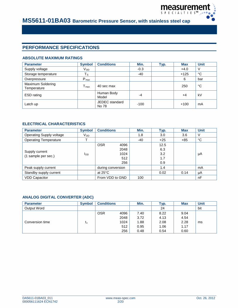
PERFORMANCE SPECIFICATIONS
ABSOLUTE MAXIMUM RATINGS Parameter Symbol Conditions Min. Typ. Max Unit Supply voltage VDD -0.3 +4.0 V Storage temperature TS -40 +125 °C Overpressure Pmax 6 bar Maximum Soldering Temperature Tmax 40 sec max 250 °C
ESD rating Human Body Model -4 +4 kV
Latch up JEDEC standard No 78 -100 +100 mA
ELECTRICAL CHARACTERISTICS
Parameter Symbol Conditions Min. Typ. Max Unit Operating Supply voltage VDD 1.8 3.0 3.6 V Operating Temperature T -40 +25 +85 °C
Supply current (1 sample per sec.) IDD
OSR 4096 2048 1024
512 256
12.5 6.3 3.2 1.7 0.9
µA
Peak supply current during conversion 1.4 mA Standby supply current at 25°C 0.02 0.14 µA VDD Capacitor From VDD to GND 100 nF
ANALOG DIGITAL CONVERTER (ADC)
Parameter Symbol Conditions Min. Typ. Max Unit Output Word 24 bit
Conversion time tc
OSR 4096 2048 1024
512 256
7.40 3.72 1.88 0.95 0.48
8.22 4.13 2.08 1.06 0.54
9.04 4.54 2.28 1.17 0.60
ms

MS5611-01BA03 Barometric Pressure Sensor, with stainless steel cap
DA5611-01BA03_011 www.meas-spec.com Oct. 26, 2012 000056111624 ECN1742 3/20
PERFORMANCE SPECIFICATIONS (CONTINUED)
PRESSURE OUTPUT CHARACTERISTICS (VDD = 3 V, T = 25°C UNLESS OTHERWISE NOTED) Parameter Conditions Min. Typ. Max Unit Operating Pressure Range Prange Full Accuracy 450 1100 mbar
Extended Pressure Range Pext Linear Range of ADC 10 1200 mbar
Total Error Band, no autozero
at 25°C, 700..1100 mbar at 0..50°C, 450..1100 mbar at -20..85°C, 450..1100 mbar at -40..85°C, 450..1100 mbar
-1.5 -2.0 -3.5 -6.0
+1.5 +2.0 +3.5 +6.0
mbar
Total Error Band, autozero at one pressure point
at 25°C, 700..1100 mbar at 10..50°C, 450..1100 mbar at -20..85°C, 450..1100 mbar at -40..85°C, 450..1100 mbar
-0.5 -1.0 -2.5 -5.0
+0.5 +1.0 +2.5 +5.0
mbar
Maximum error with supply voltage VDD = 1.8 V … 3.6 V ±2.5 mbar
Long-term stability ±1 mbar/yr Recovering time after reflow (1) 7 days
Resolution RMS
OSR 4096 2048 1024
512 256
0.012 0.018 0.027 0.042 0.065
mbar
(1) Time to recovering at least 66% of the reflow impact TEMPERATURE OUTPUT CHARACTERISTICS (VDD = 3 V, T = 25°C UNLESS OTHERWISE NOTED)
Parameter Conditions Min. Typ. Max Unit
Absolute Accuracy at 25°C -20..85°C -40..85°C
-0.8 -2.0 -4.0
+0.8 +2.0 +4.0
°C
Maximum error with supply voltage VDD = 1.8 V … 3.6 V ±0.5 °C
Resolution RMS
OSR 4096 2048 1024
512 256
0.002 0.003 0.005 0.008 0.012
°C
MS5611-01BA03 Barometric Pressure Sensor, with stainless steel cap
DA5611-01BA03_011 www.meas-spec.com Oct. 26, 2012 000056111624 ECN1742 4/20
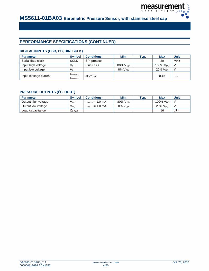
PERFORMANCE SPECIFICATIONS (CONTINUED)
DIGITAL INPUTS (CSB, I2C, DIN, SCLK) Parameter Symbol Conditions Min. Typ. Max Unit Serial data clock SCLK SPI protocol 20 MHz Input high voltage VIH Pins CSB 80% VDD 100% VDD V Input low voltage VIL 0% VDD 20% VDD V
Input leakage current I leak25°C I leak85°C at 25°C 0.15 µA
PRESSURE OUTPUTS (I2C, DOUT)
Parameter Symbol Conditions Min. Typ. Max Unit Output high voltage VOH Isource = 1.0 mA 80% VDD 100% VDD V Output low voltage VOL Isink = 1.0 mA 0% VDD 20% VDD V Load capacitance CLOAD 16 pF
MS5611-01BA03 Barometric Pressure Sensor, with stainless steel cap
DA5611-01BA03_011 www.meas-spec.com Oct. 26, 2012 000056111624 ECN1742 5/20
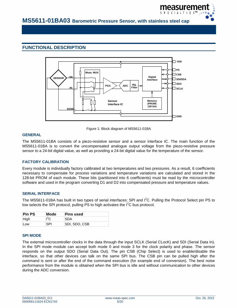
FUNCTIONAL DESCRIPTION
VDD
GND
PS
SCLK
SDO
SDI/SDA
Meas. MUX
ADC
DigitalInterface
Memory(PROM)128 bits
SENSOR
SGND
+IN
-INdig.
Filter
SensorInterface IC
PGA
CSB
Figure 1: Block diagram of MS5611-01BA
GENERAL The MS5611-01BA consists of a piezo-resistive sensor and a sensor interface IC. The main function of the MS5611-01BA is to convert the uncompensated analogue output voltage from the piezo-resistive pressure sensor to a 24-bit digital value, as well as providing a 24-bit digital value for the temperature of the sensor. FACTORY CALIBRATION Every module is individually factory calibrated at two temperatures and two pressures. As a result, 6 coefficients necessary to compensate for process variations and temperature variations are calculated and stored in the 128-bit PROM of each module. These bits (partitioned into 6 coefficients) must be read by the microcontroller software and used in the program converting D1 and D2 into compensated pressure and temperature values. SERIAL INTERFACE The MS5611-01BA has built in two types of serial interfaces: SPI and I2C. Pulling the Protocol Select pin PS to low selects the SPI protocol, pulling PS to high activates the I2C bus protocol. Pin PS Mode Pins used High I2C SDA Low SPI SDI, SDO, CSB SPI MODE The external microcontroller clocks in the data through the input SCLK (Serial CLocK) and SDI (Serial Data In). In the SPI mode module can accept both mode 0 and mode 3 for the clock polarity and phase. The sensor responds on the output SDO (Serial Data Out). The pin CSB (Chip Select) is used to enable/disable the interface, so that other devices can talk on the same SPI bus. The CSB pin can be pulled high after the command is sent or after the end of the command execution (for example end of conversion). The best noise performance from the module is obtained when the SPI bus is idle and without communication to other devices during the ADC conversion.
MS5611-01BA03 Barometric Pressure Sensor, with stainless steel cap
DA5611-01BA03_011 www.meas-spec.com Oct. 26, 2012 000056111624 ECN1742 6/20
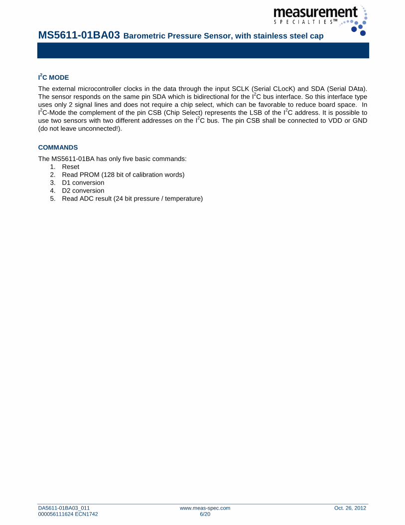
I2C MODE The external microcontroller clocks in the data through the input SCLK (Serial CLocK) and SDA (Serial DAta). The sensor responds on the same pin SDA which is bidirectional for the I2C bus interface. So this interface type uses only 2 signal lines and does not require a chip select, which can be favorable to reduce board space. In I2C-Mode the complement of the pin CSB (Chip Select) represents the LSB of the I2C address. It is possible to use two sensors with two different addresses on the I2C bus. The pin CSB shall be connected to VDD or GND (do not leave unconnected!). COMMANDS The MS5611-01BA has only five basic commands:
1. Reset 2. Read PROM (128 bit of calibration words) 3. D1 conversion 4. D2 conversion 5. Read ADC result (24 bit pressure / temperature)
MS5611-01BA03 Barometric Pressure Sensor, with stainless steel cap
DA5611-01BA03_011 www.meas-spec.com Oct. 26, 2012 000056111624 ECN1742 7/20
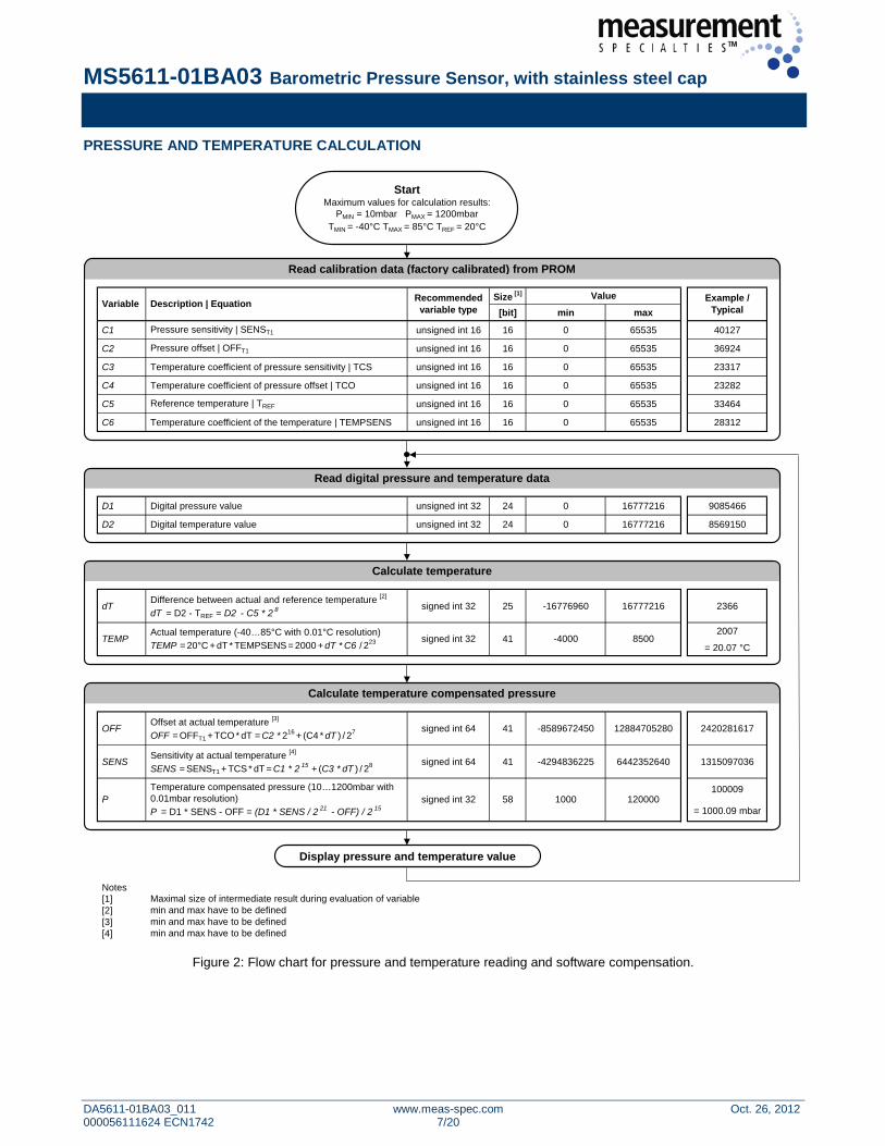
PRESSURE AND TEMPERATURE CALCULATION
Size [1]
[bit] min max
C1 Pressure sensitivity | SENST1 unsigned int 16 16 0 65535 40127
C2 Pressure offset | OFFT1 unsigned int 16 16 0 65535 36924
C3 Temperature coefficient of pressure sensitivity | TCS unsigned int 16 16 0 65535 23317
C4 Temperature coefficient of pressure offset | TCO unsigned int 16 16 0 65535 23282
C5 Reference temperature | TREF unsigned int 16 16 0 65535 33464
C6 Temperature coefficient of the temperature | TEMPSENS unsigned int 16 16 0 65535 28312
D1 Digital pressure value unsigned int 32 24 0 16777216 9085466
D2 Digital temperature value unsigned int 32 24 0 16777216 8569150
dTDifference between actual and reference temperature [2]
dT = D2 - TREF = D2 - C5 * 2 8 signed int 32 25 -16776960 16777216 2366
2007
= 20.07 °C
OFFOffset at actual temperature [3]
OFF = OFFT1 + TCO * dT = C2 * 216 + (C4 * dT ) / 27 signed int 64 41 -8589672450 12884705280 2420281617
SENSSensitivity at actual temperature [4]
SENS = SENST1 + TCS * dT = C1 * 2 15 + (C3 * dT ) / 28 signed int 64 41 -4294836225 6442352640 1315097036
100009
= 1000.09 mbar
Notes[1][2][3][4]
min and max have to be definedmin and max have to be defined
Maximal size of intermediate result during evaluation of variable
120000100058P
Recommendedvariable typeDescription | Equation
signed int 32Actual temperature (-40…85°C with 0.01°C resolution)TEMP = 20°C + dT * TEMPSENS = 2000 + dT * C6 / 223
Read digital pressure and temperature data
signed int 32Temperature compensated pressure (10…1200mbar with 0.01mbar resolution)P = D1 * SENS - OFF = (D1 * SENS / 2 21 - OFF) / 2 15
min and max have to be defined
Convert calibration data into coefficients (see bit pattern of W1 to W4)
Variable Example / Typical
Value
Calculate temperature compensated pressure
8500-4000TEMP 41
StartMaximum values for calculation results:
PMIN = 10mbar PMAX = 1200mbarTMIN = -40°C TMAX = 85°C TREF = 20°C
Read calibration data (factory calibrated) from PROM
Read digital pressure and temperature data
Calculate temperature
Calculate temperature compensated pressure
Display pressure and temperature value
Figure 2: Flow chart for pressure and temperature reading and software compensation.
MS5611-01BA03 Barometric Pressure Sensor, with stainless steel cap
DA5611-01BA03_011 www.meas-spec.com Oct. 26, 2012 000056111624 ECN1742 8/20
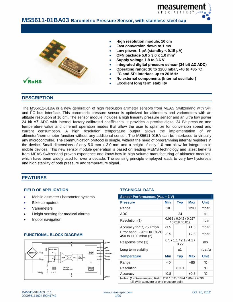
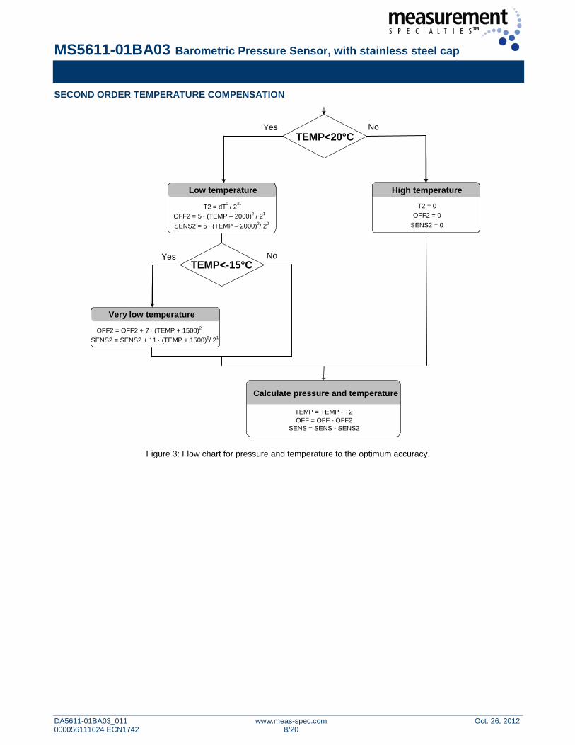
SECOND ORDER TEMPERATURE COMPENSATION
Yes No
SENS2 = 5 ⋅ (TEMP – 2000)2/ 22
SENS2 = 0
SENS = SENS - SENS2
TEMP<20°C
Low temperature
T2 = dT 2 / 2 31 OFF2 = 0
T2 = 0 OFF2 = 5 ⋅ (TEMP – 2000)2 / 21
OFF = OFF - OFF2 TEMP = TEMP - T2
Low temperature High temperature
Calculate pressure and temperature
TEMP<-15°C No Yes
SENS2 = SENS2 + 11 ⋅ (TEMP + 1500)2/ 21
Low temperature
OFF2 = OFF2 + 7 ⋅ (TEMP + 1500)2 Very low temperature
Figure 3: Flow chart for pressure and temperature to the optimum accuracy.
MS5611-01BA03 Barometric Pressure Sensor, with stainless steel cap
DA5611-01BA03_011 www.meas-spec.com Oct. 26, 2012 000056111624 ECN1742 9/20
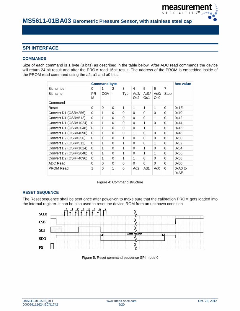
SPI INTERFACE
COMMANDS Size of each command is 1 byte (8 bits) as described in the table below. After ADC read commands the device will return 24 bit result and after the PROM read 16bit result. The address of the PROM is embedded inside of the PROM read command using the a2, a1 and a0 bits.
Command byte hex value Bit number 0 1 2 3 4 5 6 7 Bit name PR
M COV - Typ Ad2/
Os2 Ad1/Os1
Ad0/Os0
Stop
Command Reset 0 0 0 1 1 1 1 0 0x1E Convert D1 (OSR=256) 0 1 0 0 0 0 0 0 0x40 Convert D1 (OSR=512) 0 1 0 0 0 0 1 0 0x42 Convert D1 (OSR=1024) 0 1 0 0 0 1 0 0 0x44 Convert D1 (OSR=2048) 0 1 0 0 0 1 1 0 0x46 Convert D1 (OSR=4096) 0 1 0 0 1 0 0 0 0x48 Convert D2 (OSR=256) 0 1 0 1 0 0 0 0 0x50 Convert D2 (OSR=512) 0 1 0 1 0 0 1 0 0x52 Convert D2 (OSR=1024) 0 1 0 1 0 1 0 0 0x54 Convert D2 (OSR=2048) 0 1 0 1 0 1 1 0 0x56 Convert D2 (OSR=4096) 0 1 0 1 1 0 0 0 0x58 ADC Read 0 0 0 0 0 0 0 0 0x00 PROM Read 1 0 1 0 Ad2 Ad1 Ad0 0 0xA0 to
0xAE
Figure 4: Command structure
RESET SEQUENCE The Reset sequence shall be sent once after power-on to make sure that the calibration PROM gets loaded into the internal register. It can be also used to reset the device ROM from an unknown condition
Figure 5: Reset command sequence SPI mode 0
MS5611-01BA03 Barometric Pressure Sensor, with stainless steel cap
DA5611-01BA03_011 www.meas-spec.com Oct. 26, 2012 000056111624 ECN1742 10/20
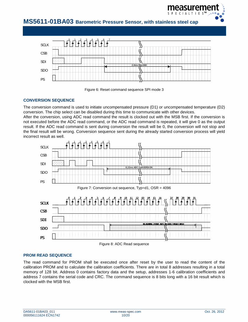
Figure 6: Reset command sequence SPI mode 3
CONVERSION SEQUENCE The conversion command is used to initiate uncompensated pressure (D1) or uncompensated temperature (D2) conversion. The chip select can be disabled during this time to communicate with other devices. After the conversion, using ADC read command the result is clocked out with the MSB first. If the conversion is not executed before the ADC read command, or the ADC read command is repeated, it will give 0 as the output result. If the ADC read command is sent during conversion the result will be 0, the conversion will not stop and the final result will be wrong. Conversion sequence sent during the already started conversion process will yield incorrect result as well.
0 1 2 3 4 5 6 7
SCLK
CSB
SDI
SDO
PS
8.22ms ADC CONVERSION
Figure 7: Conversion out sequence, Typ=d1, OSR = 4096
Figure 8: ADC Read sequence
PROM READ SEQUENCE The read command for PROM shall be executed once after reset by the user to read the content of the calibration PROM and to calculate the calibration coefficients. There are in total 8 addresses resulting in a total memory of 128 bit. Address 0 contains factory data and the setup, addresses 1-6 calibration coefficients and address 7 contains the serial code and CRC. The command sequence is 8 bits long with a 16 bit result which is clocked with the MSB first.
0 1 2 3 4 5 6 7
SCLK
CSB
SDI
SDO
PS
2.8ms RELOAD
MS5611-01BA03 Barometric Pressure Sensor, with stainless steel cap
DA5611-01BA03_011 www.meas-spec.com Oct. 26, 2012 000056111624 ECN1742 11/20
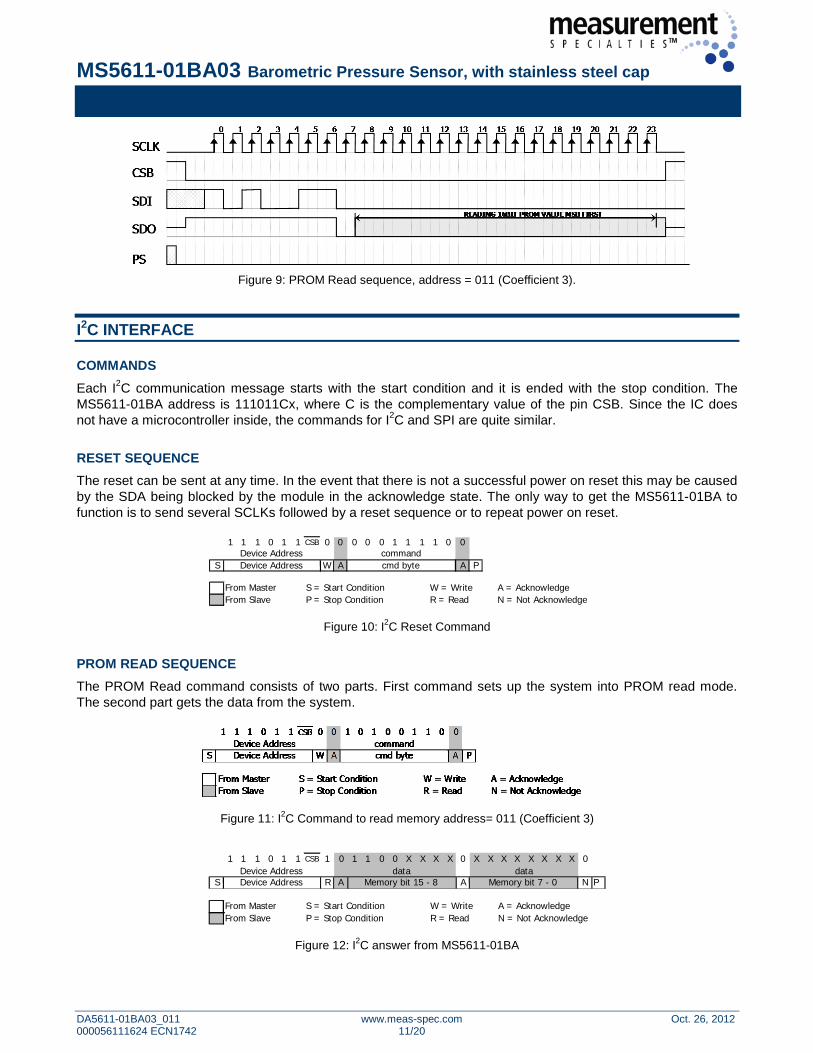
Figure 9: PROM Read sequence, address = 011 (Coefficient 3).
I2C INTERFACE
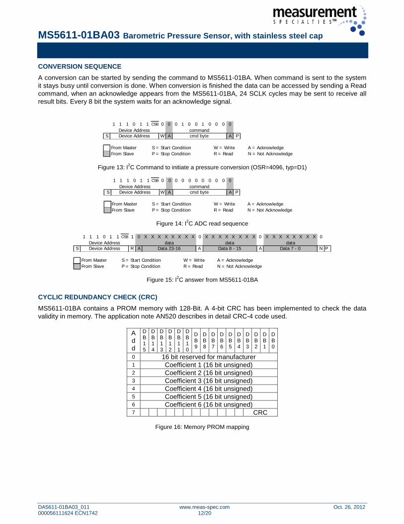
COMMANDS Each I2C communication message starts with the start condition and it is ended with the stop condition. The MS5611-01BA address is 111011Cx, where C is the complementary value of the pin CSB. Since the IC does not have a microcontroller inside, the commands for I2C and SPI are quite similar. RESET SEQUENCE The reset can be sent at any time. In the event that there is not a successful power on reset this may be caused by the SDA being blocked by the module in the acknowledge state. The only way to get the MS5611-01BA to function is to send several SCLKs followed by a reset sequence or to repeat power on reset.
1 1 1 0 1 1 CSB 0 0 0 0 0 1 1 1 1 0 0
S W A A P
From Master S = Start Condition W = Write A = AcknowledgeFrom Slave P = Stop Condition R = Read N = Not Acknowledge
cmd byteDevice AddressDevice Address
command
Figure 10: I2C Reset Command PROM READ SEQUENCE The PROM Read command consists of two parts. First command sets up the system into PROM read mode. The second part gets the data from the system.
Figure 11: I2C Command to read memory address= 011 (Coefficient 3)
1 1 1 0 1 1 CSB 1 0 1 1 0 0 X X X X 0 X X X X X X X X 0
S R A A N P
From Master S = Start Condition W = Write A = AcknowledgeFrom Slave P = Stop Condition R = Read N = Not Acknowledge
data dataDevice Address Memory bit 15 - 8 Memory bit 7 - 0Device Address
Figure 12: I2C answer from MS5611-01BA
MS5611-01BA03 Barometric Pressure Sensor, with stainless steel cap
DA5611-01BA03_011 www.meas-spec.com Oct. 26, 2012 000056111624 ECN1742 12/20
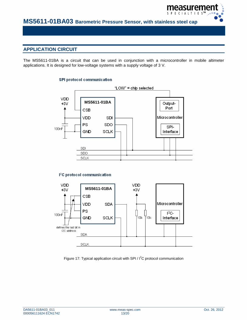
CONVERSION SEQUENCE A conversion can be started by sending the command to MS5611-01BA. When command is sent to the system it stays busy until conversion is done. When conversion is finished the data can be accessed by sending a Read command, when an acknowledge appears from the MS5611-01BA, 24 SCLK cycles may be sent to receive all result bits. Every 8 bit the system waits for an acknowledge signal.
1 1 1 0 1 1 CSB 0 0 0 1 0 0 1 0 0 0 0
S W A A P
From Master S = Start Condition W = Write A = AcknowledgeFrom Slave P = Stop Condition R = Read N = Not Acknowledge
commandcmd byte
Device AddressDevice Address
Figure 13: I2C Command to initiate a pressure conversion (OSR=4096, typ=D1)
1 1 1 0 1 1 CSB 0 0 0 0 0 0 0 0 0 0 0
S W A A P
From Master S = Start Condition W = Write A = AcknowledgeFrom Slave P = Stop Condition R = Read N = Not Acknowledge
commandDevice AddressDevice Address cmd byte
Figure 14: I2C ADC read sequence
1 1 1 0 1 1 CSB 1 0 X X X X X X X X 0 X X X X X X X X 0 X X X X X X X X 0
S R A A A N P
From Master S = Start Condition W = Write A = AcknowledgeFrom Slave P = Stop Condition R = Read N = Not Acknowledge
data data dataDevice AddressDevice Address
Data 23-16 Data 7 - 0Data 8 - 15
Figure 15: I2C answer from MS5611-01BA
CYCLIC REDUNDANCY CHECK (CRC) MS5611-01BA contains a PROM memory with 128-Bit. A 4-bit CRC has been implemented to check the data validity in memory. The application note AN520 describes in detail CRC-4 code used.
A d d
DB15
DB14
DB13
DB12
DB11
DB10
DB9
DB8
DB7
DB6
DB5
DB4
DB3
DB2
DB1
DB0
0 16 bit reserved for manufacturer 1 Coefficient 1 (16 bit unsigned) 2 Coefficient 2 (16 bit unsigned) 3 Coefficient 3 (16 bit unsigned) 4 Coefficient 4 (16 bit unsigned) 5 Coefficient 5 (16 bit unsigned) 6 Coefficient 6 (16 bit unsigned) 7 CRC
Figure 16: Memory PROM mapping
MS5611-01BA03 Barometric Pressure Sensor, with stainless steel cap
DA5611-01BA03_011 www.meas-spec.com Oct. 26, 2012 000056111624 ECN1742 13/20
APPLICATION CIRCUIT
The MS5611-01BA is a circuit that can be used in conjunction with a microcontroller in mobile altimeter applications. It is designed for low-voltage systems with a supply voltage of 3 V.
Figure 17: Typical application circuit with SPI / I2C protocol communication
MS5611-01BA
MS5611-01BA
MS5611-01BA03 Barometric Pressure Sensor, with stainless steel cap
DA5611-01BA03_011 www.meas-spec.com Oct. 26, 2012 000056111624 ECN1742 14/20
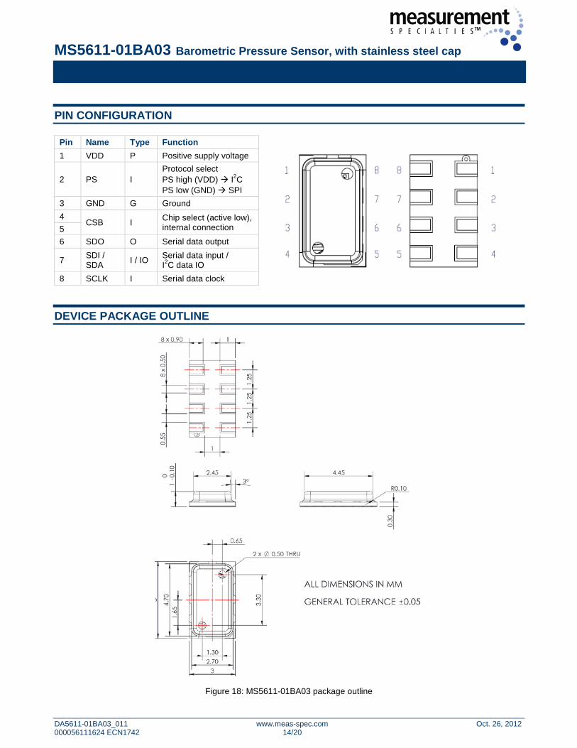
PIN CONFIGURATION
Pin Name Type Function
1 VDD P Positive supply voltage
2 PS I Protocol select PS high (VDD) I2C PS low (GND) SPI
3 GND G Ground 4
CSB I Chip select (active low), internal connection 5
6 SDO O Serial data output
7 SDI / SDA I / IO Serial data input /
I2C data IO 8 SCLK I Serial data clock
DEVICE PACKAGE OUTLINE
Figure 18: MS5611-01BA03 package outline
MS5611-01BA03 Barometric Pressure Sensor, with stainless steel cap
DA5611-01BA03_011 www.meas-spec.com Oct. 26, 2012 000056111624 ECN1742 15/20
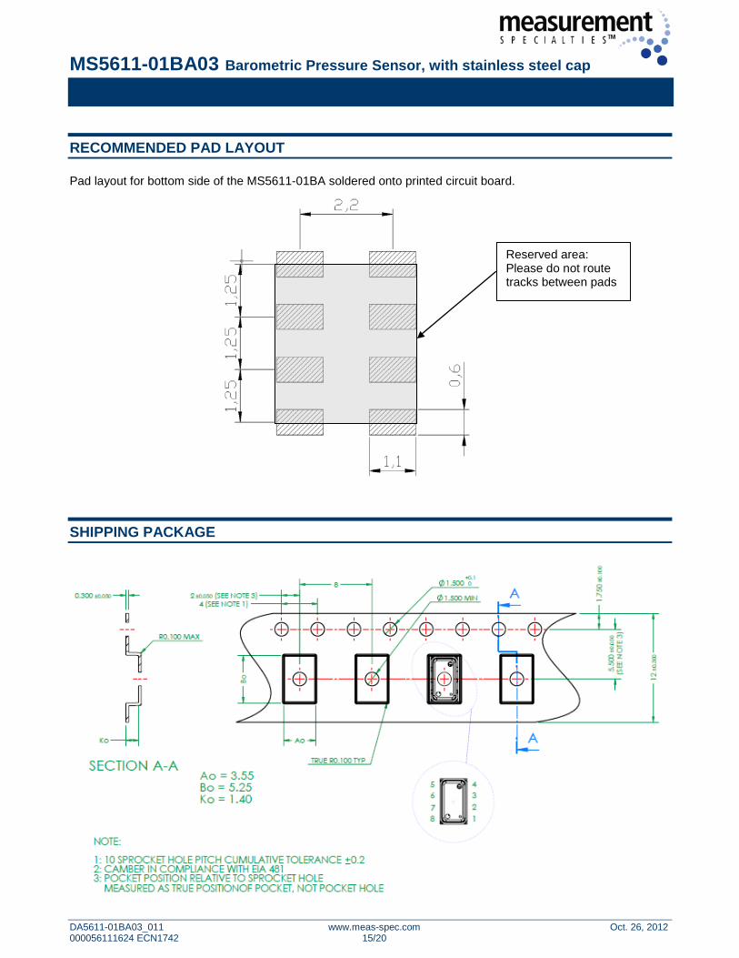
RECOMMENDED PAD LAYOUT
Pad layout for bottom side of the MS5611-01BA soldered onto printed circuit board.
SHIPPING PACKAGE
Reserved area: Please do not route tracks between pads
MS5611-01BA03 Barometric Pressure Sensor, with stainless steel cap
DA5611-01BA03_011 www.meas-spec.com Oct. 26, 2012 000056111624 ECN1742 16/20
MOUNTING AND ASSEMBLY CONSIDERATIONS
SOLDERING Please refer to the application note AN808 available on our website for all soldering issues. MOUNTING The MS5611-01BA can be placed with automatic Pick & Place equipment using vacuum nozzles. It will not be damaged by the vacuum. Due to the low stress assembly the sensor does not show pressure hysteresis effects. It is important to solder all contact pads. CONNECTION TO PCB The package outline of the module allows the use of a flexible PCB for interconnection. This can be important for applications in watches and other special devices. CLEANING The MS5611-01BA has been manufactured under cleanroom conditions. It is therefore recommended to assemble the sensor under class 10’000 or better conditions. Should this not be possible, it is recommended to protect the sensor opening during assembly from entering particles and dust. To avoid cleaning of the PCB, solder paste of type “no-clean” shall be used. Cleaning might damage the sensor! ESD PRECAUTIONS The electrical contact pads are protected against ESD up to 4 kV HBM (human body model). It is therefore essential to ground machines and personnel properly during assembly and handling of the device. The MS5611-01BA is shipped in antistatic transport boxes. Any test adapters or production transport boxes used during the assembly of the sensor shall be of an equivalent antistatic material. DECOUPLING CAPACITOR Particular care must be taken when connecting the device to the power supply. A 100 nF ceramic capacitor must be placed as close as possible to the MS5611-01BA VDD pin. This capacitor will stabilize the power supply during data conversion and thus, provide the highest possible accuracy.
MS5611-01BA03 Barometric Pressure Sensor, with stainless steel cap
DA5611-01BA03_011 www.meas-spec.com Oct. 26, 2012 000056111624 ECN1742 17/20
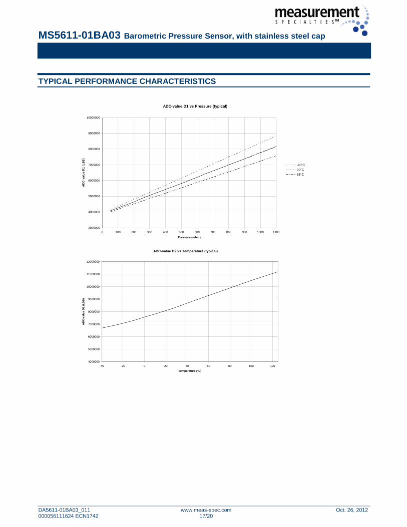
ADC-value D1 vs Pressure (typical)
3000000
4000000
5000000
6000000
7000000
8000000
9000000
10000000
0 100 200 300 400 500 600 700 800 900 1000 1100
Pressure (mbar)
AD
C-v
alue
D1
(LSB
)
-40°C20°C85°C
TYPICAL PERFORMANCE CHARACTERISTICS
ADC-value D2 vs Temperature (typical)
4000000
5000000
6000000
7000000
8000000
9000000
10000000
11000000
12000000
-40 -20 0 20 40 60 80 100 120
Temperature (°C)
AD
C-v
alue
D2
(LSB
)
MS5611-01BA03 Barometric Pressure Sensor, with stainless steel cap
DA5611-01BA03_011 www.meas-spec.com Oct. 26, 2012 000056111624 ECN1742 18/20
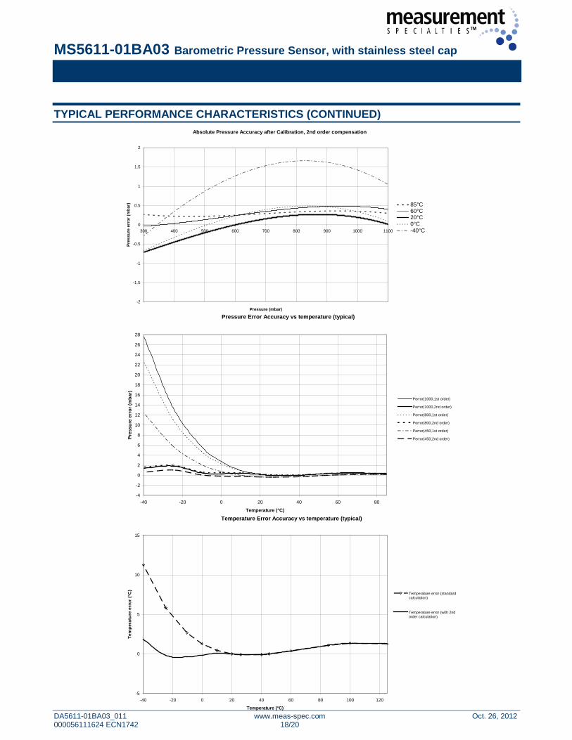
Absolute Pressure Accuracy after Calibration, 2nd order compensation
-2
-1.5
-1
-0.5
0
0.5
1
1.5
2
300 400 500 600 700 800 900 1000 1100
Pressure (mbar)
Pres
sure
err
or (m
bar)
85°C60°C20°C0°C-40°CPoly. (85°C)Poly. (60°C)Poly. (20°C)Poly. (0°C)Poly. (-40°C)
Pressure Error Accuracy vs temperature (typical)
-4
-2
0
2
4
6
8
10
12
14
16
18
20
22
24
26
28
-40 -20 0 20 40 60 80
Temperature (°C)
Pres
sure
err
or (m
bar)
Perror(1000,1st order)
Perror(1000,2nd order)
Perror(800,1st order)
Perror(800,2nd order)
Perror(450,1st order)
Perror(450,2nd order)
Temperature Error Accuracy vs temperature (typical)
-5
0
5
10
15
-40 -20 0 20 40 60 80 100 120
Temperature (°C)
Tem
pera
ture
err
or (°
C)
Temperature error (standardcalculation)
Temperature error (with 2ndorder calculation)
TYPICAL PERFORMANCE CHARACTERISTICS (CONTINUED)
85°C 60°C 20°C 0°C -40°C
MS5611-01BA03 Barometric Pressure Sensor, with stainless steel cap
DA5611-01BA03_011 www.meas-spec.com Oct. 26, 2012 000056111624 ECN1742 19/20
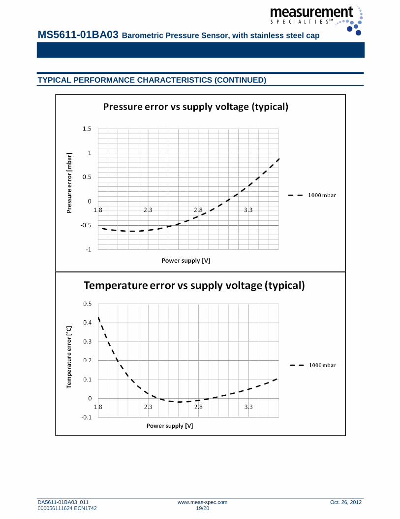
TYPICAL PERFORMANCE CHARACTERISTICS (CONTINUED)
MS5611-01BA03 Barometric Pressure Sensor, with stainless steel cap
DA5611-01BA03_011 www.meas-spec.com Oct. 26, 2012 000056111624 ECN1742 20/20
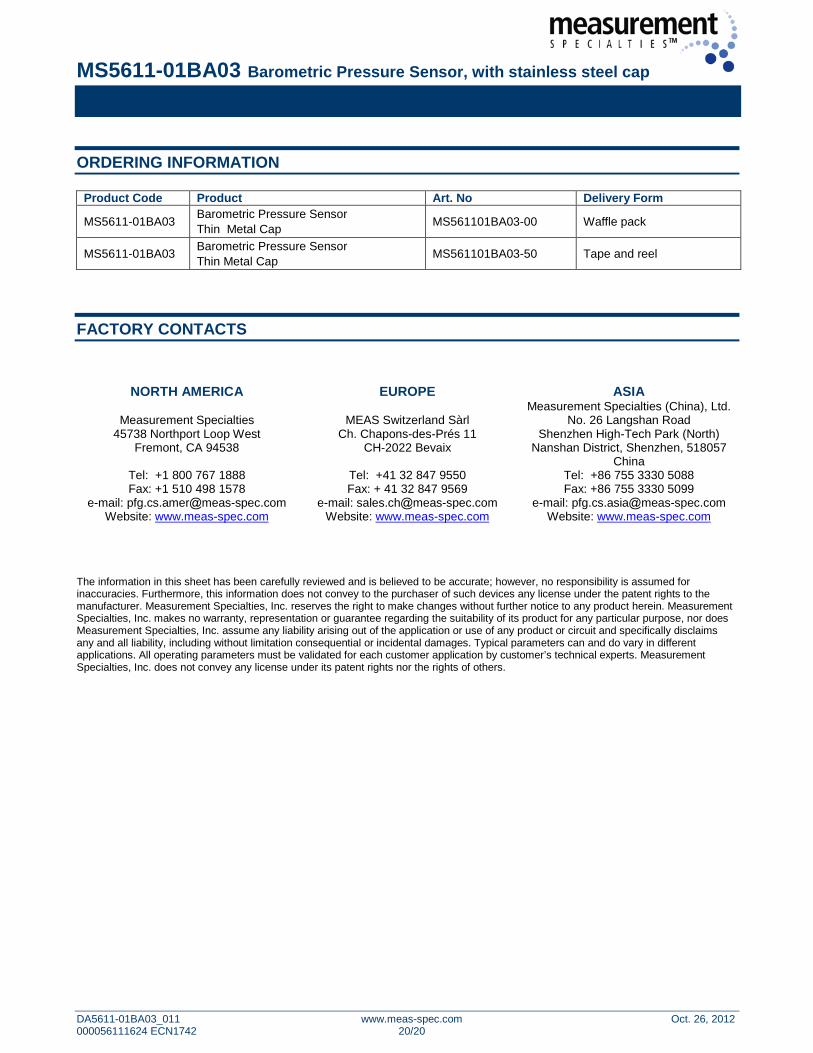
ORDERING INFORMATION
Product Code Product Art. No Delivery Form
MS5611-01BA03 Barometric Pressure Sensor Thin Metal Cap MS561101BA03-00 Waffle pack
MS5611-01BA03 Barometric Pressure Sensor Thin Metal Cap MS561101BA03-50 Tape and reel
FACTORY CONTACTS
NORTH AMERICA EUROPE ASIA
Measurement Specialties 45738 Northport Loop West
Fremont, CA 94538
Tel: +1 800 767 1888 Fax: +1 510 498 1578
e-mail: pfg.cs.amerameas-spec.com Website: www.meas-spec.com
MEAS Switzerland Sàrl Ch. Chapons-des-Prés 11
CH-2022 Bevaix
Tel: +41 32 847 9550 Fax: + 41 32 847 9569
e-mail: sales.chameas-spec.com Website: www.meas-spec.com
Measurement Specialties (China), Ltd. No. 26 Langshan Road
Shenzhen High-Tech Park (North) Nanshan District, Shenzhen, 518057
China Tel: +86 755 3330 5088 Fax: +86 755 3330 5099
e-mail: pfg.cs.asiaameas-spec.com Website: www.meas-spec.com
The information in this sheet has been carefully reviewed and is believed to be accurate; however, no responsibility is assumed for inaccuracies. Furthermore, this information does not convey to the purchaser of such devices any license under the patent rights to the manufacturer. Measurement Specialties, Inc. reserves the right to make changes without further notice to any product herein. Measurement Specialties, Inc. makes no warranty, representation or guarantee regarding the suitability of its product for any particular purpose, nor does Measurement Specialties, Inc. assume any liability arising out of the application or use of any product or circuit and specifically disclaims any and all liability, including without limitation consequential or incidental damages. Typical parameters can and do vary in different applications. All operating parameters must be validated for each customer application by customer’s technical experts. Measurement Specialties, Inc. does not convey any license under its patent rights nor the rights of others.