Motorless Type Electric Actuators
124
RoHS Parallel motor type Series LEF Electric Actuators Motorless Type Your motor and driver can be used together! Manufacturers of compatible motors: 15 companies Y Y Y Y Y Y Y Y Y Y Y Y Y Y o o o o o o o ou u u ur r r r r r r r r r r m m m mo o o o o o o o o ot t t t t t t t t t t o o o o o o or r r r r r r r r r r a a a a a a a a a a a a an n n n nd d d d d d d d d d d d d d d d d d d d d d d d d d d dr r r r ri i iv v v v v v ve e e e e e er r r r r r r r r r r c c c c c c c c c c c c ca a a a a a a a a an n n n b b b b b b b b b b b b b be e e e e e e e e e e u u u u u us s s s s s s se e e e e e e e e ed d d d d d d d d d d d d d t t t t t t t t t t o o o o o o o o o og g g g g g g g g g g ge e e e e et t t t t t t t t th h h h h h h h h h h h h he e e e e e e e e e er r r r r r r r r r r! ! ! M M M M M M M M Ma a a a an n n n nu u u uf f f f f f f f f f f f f fa a a a a a ac c c c c c c c c ct t t t t t t t t t tu u u ur r r r r r re e e e e e e er r r r r rs s s s s s s s o o o o o o o o o o o o o of f f f f f f f f f f f f f c c c c c c c c c c c c c co o o o o o o o o o om m m m mp p p p p p p p p a a a a a a a a a a at t t t t t t t t t ti ib b b b b b b b b b b b b bl l le e e e e e e e m m m mo o o o o o o o o o ot t t t t t t t t t to o o o o o or r r r r s s s s s s s s : : : : c c c c c c c c c c c c co o o o o o o o o o om m m mp p p p p p p p a a a a a a a a a a an n n ni i ie e e e e e e e es s s s s s s s s s s Your motor and driver can be used together! Manufacturers of compatible motors: 15 companies Parallel motor type Slider Type Series LEF Ball Screw Drive/Series LEFS Stroke [mm] 50 to 800 50 to 1000 150 to 1200 Size 25 32 40 Belt Drive/Series LEFB Stroke [mm] 300 to 2000 300 to 2500 300 to 3000 Size 25 32 40 Belt drive Series LEFB Ball screw drive Series LEFS High Rigidity Slider Type Series LEJ Ball screw drive Series LEJS Ball Screw Drive/Series LEJS Stroke [mm] 200 to 1200 300 to 1500 Size 40 63 J rew drive EJS Stroke [mm] 30 to 400 30 to 500 100 to 800 Size 25 32 63 Rod Type Series LEY Guide Rod Type Series LEYG Stroke [mm] 30 to 300 Size 25 32 SANYO DENKI CO., LTD. Panasonic Corporation NIDEC SANKYO CORPORATION Mitsubishi Electric Corporation OMRON Corporation FANUC CORPORATION KEYENCE CORPORATION YASKAWA Electric Corporation Rockwell Automation, Inc. (Allen-Bradley) Beckhoff Automation GmbH Siemens AG FUJI ELECTRIC CO., LTD. ORIENTAL MOTOR Co., Ltd. FASTECH Co., Ltd. Delta Electronics, Inc. CAT.EUS100-111Bb-UK Series LE
Transcript of Motorless Type Electric Actuators
RoHS
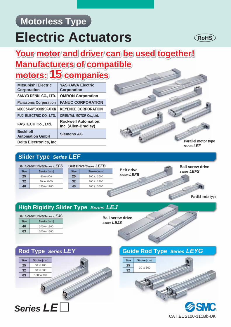
Parallel motor type
Series LEF
Electric Actuators
Motorless Type
Your motor and driver can be used together!
Manufacturers of compatible
motors: 15 companies
YYYYYYYYYYYYYYoooooooouuuurrrrrrrrrrr mmmmooooooooootttttttttttooooooorrrrrrrrrrr aaaaaaaaaaaaannnnndddddddddddddd ddddddddddddddrrrrriiivvvvvvveeeeeeerrrrrrrrrrr cccccccccccccaaaaaaaaaannnn bbbbbbbbbbbbbbeeeeeeeeeee uuuuuusssssssseeeeeeeeeedddddddddddddd ttttttttttooooooooooggggggggggggeeeeeetttttttttthhhhhhhhhhhhhheeeeeeeeeeerrrrrrrrrrr!!!
MMMMMMMMMaaaaannnnnuuuuffffffffffffffaaaaaaacccccccccctttttttttttuuuurrrrrrreeeeeeeerrrrrrssssssss ooooooooooooooffffffffffffff ccccccccccccccooooooooooommmmmppppppppppppppaaaaaaaaaaatttttttttttiibbbbbbbbbbbbbbllleeeeeeee
mmmmoooooooooootttttttttttooooooorrrrrrssssssss:::: cccccccccccccooooooooooommmmppppppppppppppaaaaaaaaaaannnniiieeeeeeeeesssssssssss
Your motor and driver can be used together!
Manufacturers of compatible
motors: 15 companies
Parallel motor type
Slider Type Series LEF
Ball Screw Drive/Series LEFS
Stroke [mm]
50 to 800
50 to 1000
150 to 1200
Size
25
32
40
Belt Drive/Series LEFB
Stroke [mm]
300 to 2000
300 to 2500
300 to 3000
Size
25
32
40
Belt drive
Series LEFB
Ball screw drive
Series LEFS
High Rigidity Slider Type Series LEJ
Ball screw drive
Series LEJS
Ball Screw Drive/Series LEJS
Stroke [mm]
200 to 1200
300 to 1500
Size
40
63
J
rew drive
EJS
Stroke [mm]
30 to 400
30 to 500
100 to 800
Size
25
32
63
Rod Type Series LEY Guide Rod Type Series LEYG
Stroke [mm]
30 to 300
Size
25
32
SANYO DENKI CO., LTD.
Panasonic Corporation
NIDEC SANKYO CORPORATION
Mitsubishi Electric
Corporation
OMRON Corporation
FANUC CORPORATION
KEYENCE CORPORATION
YASKAWA Electric
Corporation
Rockwell Automation,
Inc. (Allen-Bradley)
Beckhoff
Automation GmbHSiemens AG
FUJI ELECTRIC CO., LTD. ORIENTAL MOTOR Co., Ltd.
FASTECH Co., Ltd.
Delta Electronics, Inc.
CAT.EUS100-111Bb-UK
Series LE�
SeriesSize
25 32 40 63
5
32
61
85
101
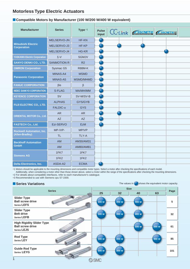
Manufacturer Series Type ∗1Pulse
input
Page
�Compatible Motors by Manufacturer (100 W/200 W/400 W equivalent)
MELSERVO-JN
MELSERVO-J3
MELSERVO-J4
Σ-V
SANMOTION R
Sysmac G5
MINAS-A4
MINAS-A5
βis
S-FLAG
SV
ALPHA5
FALDIC-α
AR
AZ
Ezi-SERVO
MP-/VP-
TL
AM
AM
1FK7
1FK2
ASDA-A2
HF-KN
HF-KP
HG-KR
SGMJV
R2
R88M-K
MSMD
MSMD/MHMD
β
MA/MH/MM
SV-M/SV-B
GYS/GYB
GYS
AR
AZ
EzM
MP/VP
TLY-A
AM30/AM31
AM80/AM81
1FK7
1FK2
ECMA
Mitsubishi ElectricCorporation
YASKAWA Electric Corporation
SANYO DENKI CO., LTD.
OMRON Corporation
Panasonic Corporation
FANUC CORPORATION
NIDEC SANKYO CORPORATION
KEYENCE CORPORATION
FUJI ELECTRIC CO., LTD.
ORIENTAL MOTOR Co., Ltd.
FASTECH Co., Ltd.
Siemens AG
Delta Electronics, Inc.
Rockwell Automation, Inc.(Allen-Bradley)
Beckhoff AutomationGmbH
∗1 Motors should be applicable to the mounting dimensions and compatible motor types. Select a motor after checking the specifications of each model.
Additionally, when considering a motor other than those shown above, select a motor within the range of the specifications after checking the mounting dimensions.
∗2 For details about compatible interfaces, refer to each manufacturer’s catalogue.
∗3 Recommended to use with Siemens cpu S7-1500.
�Series Variations
100 W 200 W 400 W
100 W 200 W 400 W
100 W 200 W
100 W 200 W 400 W
100 W 200 W
The values in shows the equivalent motor capacity.
Slider Type
Ball screw drive
Series LEFS
Slider Type
Belt drive
Series LEFB
High Rigidity Slider Type
Ball screw drive
Series LEJS
Rod Type
Series LEY
Guide Rod Type
Series LEYG
Motorless Type Electric Actuators
1
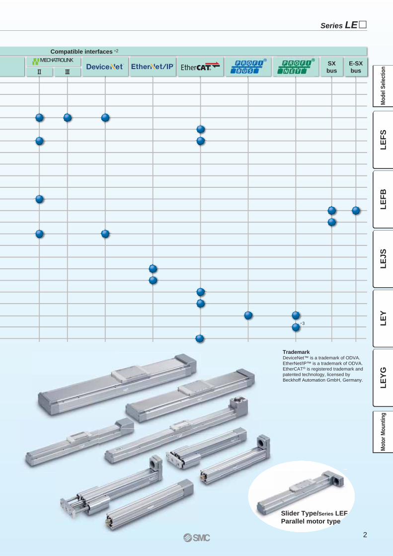
Compatible interfaces ∗2
∗3
@ #SX
bus
E-SX
bus
TrademarkDeviceNet™ is a trademark of ODVA.
EtherNet/IP™ is a trademark of ODVA.
EtherCAT® is registered trademark and
patented technology, licensed by
Beckhoff Automation GmbH, Germany.
∗3
Slider Type/Series LEF
Parallel motor type
Series LE�
2
LE
FS
LE
FB
LE
JS
LE
YL
EY
GM
od
el
Se
lec
tio
nM
oto
r M
ou
nti
ng
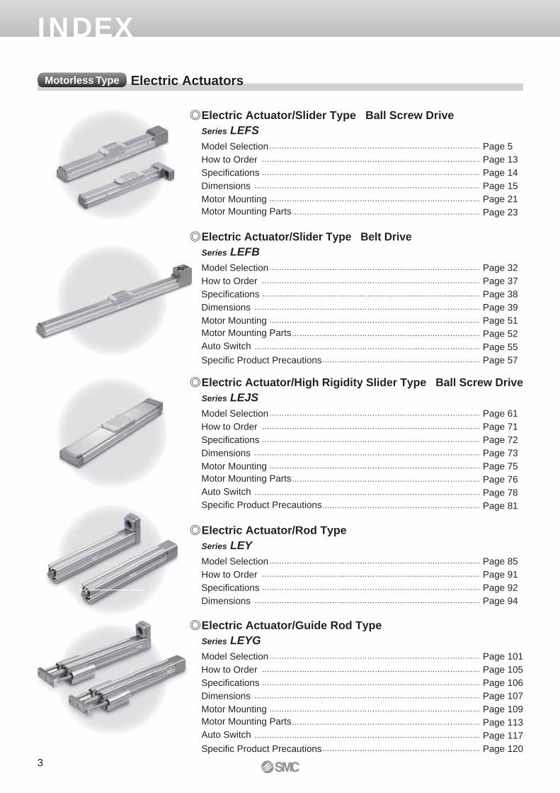
INDEX
Electric Actuator/Slider Type Ball Screw Drive
Series LEFS
Model Selection ………………………………………………………………………… Page 5
How to Order …………………………………………………………………………… Page 13
Specifi cations …………………………………………………………………………… Page 14
Dimensions ……………………………………………………………………………… Page 15
Motor Mounting ………………………………………………………………………… Page 21
Motor Mounting Parts ………………………………………………………………… Page 23
Electric Actuator/Rod Type
Series LEY
Model Selection ………………………………………………………………………… Page 85
How to Order …………………………………………………………………………… Page 91
Specifi cations …………………………………………………………………………… Page 92
Dimensions ……………………………………………………………………………… Page 94
Electric Actuator/High Rigidity Slider Type Ball Screw Drive
Series LEJS
Model Selection ………………………………………………………………………… Page 61
How to Order …………………………………………………………………………… Page 71
Specifi cations …………………………………………………………………………… Page 72
Dimensions ……………………………………………………………………………… Page 73
Motor Mounting ………………………………………………………………………… Page 75
Motor Mounting Parts ………………………………………………………………… Page 76
Auto Switch ……………………………………………………………………………… Page 78
Specifi c Product Precautions ……………………………………………………… Page 81
Electric Actuator/Guide Rod Type
Series LEYG
Model Selection ………………………………………………………………………… Page 101
How to Order …………………………………………………………………………… Page 105
Specifi cations …………………………………………………………………………… Page 106
Dimensions ……………………………………………………………………………… Page 107
Motor Mounting ………………………………………………………………………… Page 109
Motor Mounting Parts ………………………………………………………………… Page 113
Auto Switch ……………………………………………………………………………… Page 117
Specifi c Product Precautions ……………………………………………………… Page 120
Electric Actuator/Slider Type Belt Drive
Series LEFB
Model Selection ………………………………………………………………………… Page 32
How to Order …………………………………………………………………………… Page 37
Specifi cations …………………………………………………………………………… Page 38
Dimensions ……………………………………………………………………………… Page 39
Motor Mounting ………………………………………………………………………… Page 51
Motor Mounting Parts ………………………………………………………………… Page 52
Auto Switch ……………………………………………………………………………… Page 55
Specifi c Product Precautions ……………………………………………………… Page 57
Electric ActuatorsMotorless Type
3
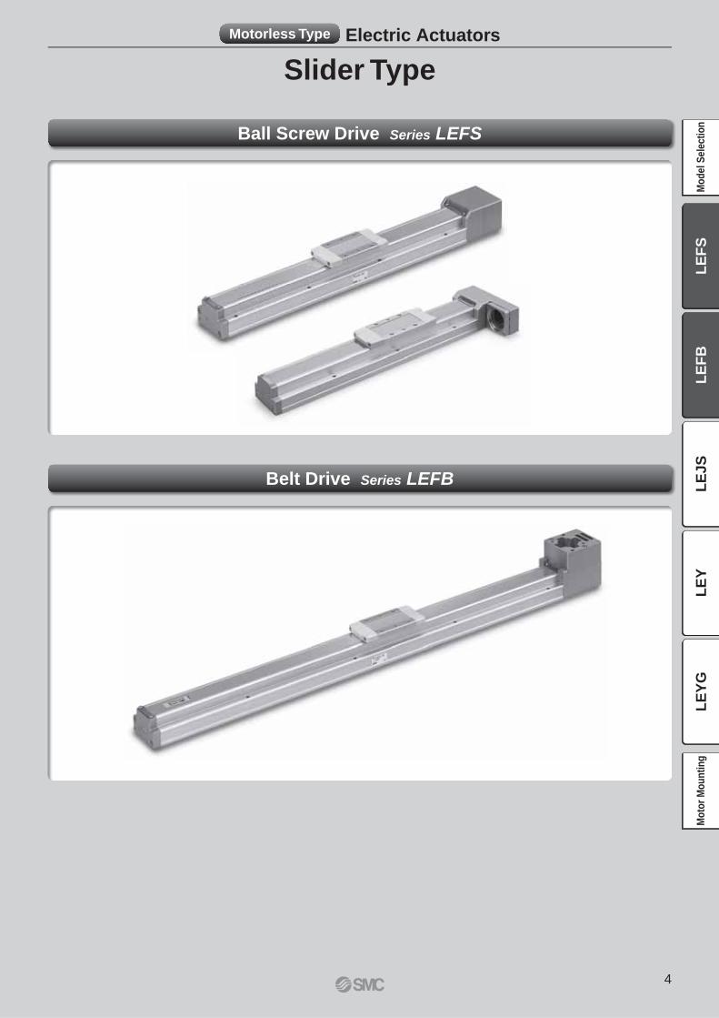
Slider Type
Motorless Type Electric Actuators
Ball Screw Drive Series LEFS
Belt Drive Series LEFB
4
LE
FS
LE
FB
LE
JS
LE
YL
EY
GM
od
el
Se
lec
tio
nM
oto
r M
ou
nti
ng
Work load [kg]
Overh
ang:
L3
[m
m]
1000 mm/s2
3000 mm/s2
5000 mm/s2
0 10 20 30 40 50 60
1500
1000
500
0
<Speed–Work Load Graph>
(LEFS40)
L : Stroke [mm]
··· (Operating condition)
V : Speed [mm/s]
··· (Operating condition)
a1: Acceleration [mm/s2]
··· (Operating condition)
a2: Deceleration [mm/s2]
··· (Operating condition)
T1: Acceleration time [s]
The time until the set speed is reached
T2: Constant speed time [s]
Time when the actuator is operating
at a constant speed
T3: Deceleration time [s]
T ime f rom the constant speed
operation until movement stops
T4: Settling time [s]
Time until positioning is completed
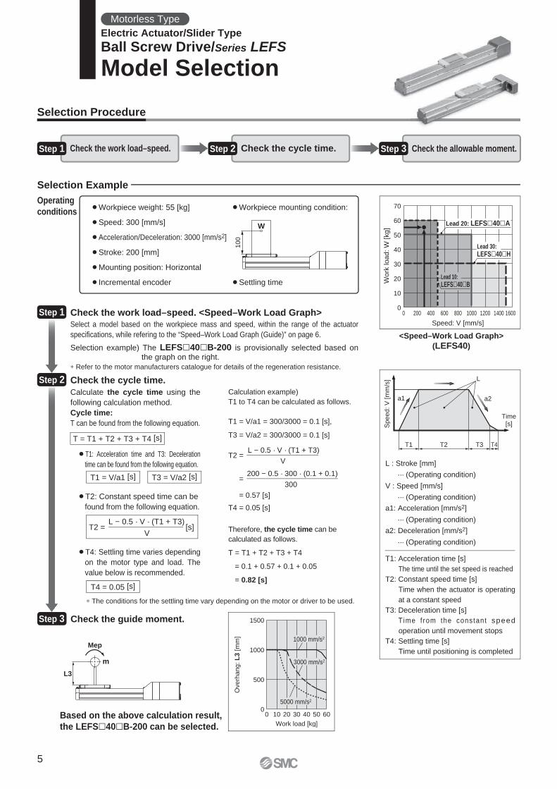
¡Workpiece weight: 55 [kg]
¡Speed: 300 [mm/s]
¡Acceleration/Deceleration: 3000 [mm/s2]
¡Stroke: 200 [mm]
¡Mounting position: Horizontal
¡Incremental encoder
¡Workpiece mounting condition:
¡Settling time
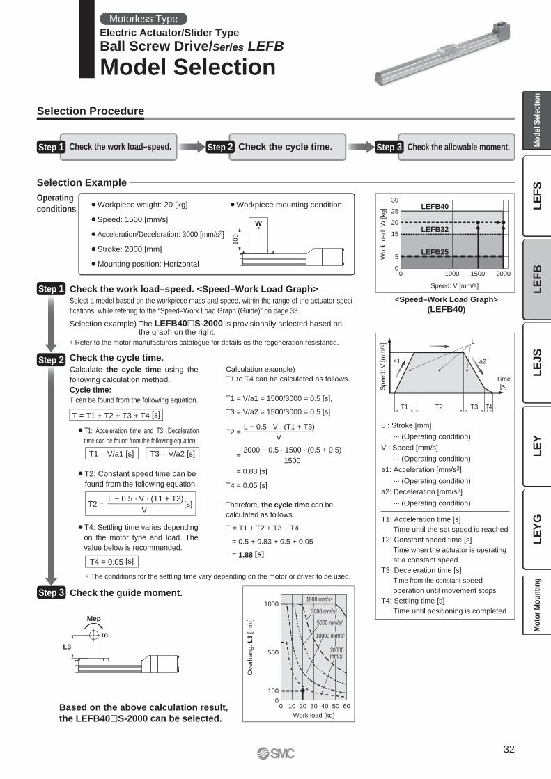
Check the work load–speed. <Speed–Work Load Graph>
Select a model based on the workpiece mass and speed, within the range of the actuator
specifi cations, while refering to the “Speed–Work Load Graph (Guide)” on page 6.
Selection example) The LEFS�40�B-200 is provisionally selected based on the graph on the right.
Check the cycle time.
Calculate the cycle time using the
following calculation method.
Cycle time:
T can be found from the following equation.
¡T4: Settling time varies depending
on the motor type and load. The
value below is recommended.
¡T2: Constant speed time can be
found from the following equation.
¡T1: Acceleration time and T3: Deceleration
time can be found from the following equation.
Check the guide moment.
Calculation example)
T1 to T4 can be calculated as follows.
T1 = V/a1 = 300/3000 = 0.1 [s],
T3 = V/a2 = 300/3000 = 0.1 [s]
T4 = 0.05 [s]
Therefore, the cycle time can be
calculated as follows.
T = T1 + T2 + T3 + T4
= 0.1 + 0.57 + 0.1 + 0.05
= 0.82 [s]
T2 =
=
= 0.57 [s]
∗ The conditions for the settling time vary depending on the motor or driver to be used.
Selection Procedure
Selection Example
Operating
conditions
T = T1 + T2 + T3 + T4 [s]
T4 = 0.05 [s]
T1 = V/a1 [s] T3 = V/a2 [s]
T2 = [s]L − 0.5 · V · (T1 + T3)
V
Step 1
Step 2
Step 3
Based on the above calculation result,
the LEFS�40�B-200 can be selected.
L − 0.5 · V · (T1 + T3)
V
200 − 0.5 · 300 · (0.1 + 0.1)
300
Step 1 Check the work load–speed. Step 2 Check the cycle time. Step 3 Check the allowable moment.
∗ Refer to the motor manufacturers catalogue for details of the regeneration resistance.
Motorless Type
Electric Actuator/Slider Type
Ball Screw Drive/Series LEFS
Model Selection
10
0
W
L3
Mep
m
T1
a1 a2
L
Speed:
V [
mm
/s]
Time[s]
T2 T3 T4
0
10
20
30
40
50
60
70
0 200 400 600 800 1000 1200 1400 1600
Work
load:
W [
kg]
Speed: V [mm/s]
Lead 20: LEFS 40 A
Lead 10:
LEFS 40 B
Lead 30:
LEFS 40 H
5
0
5
10
15
20
25
30
0 200 400 600 800 1000 1200 1400 1600
Wo
rk lo
ad
[kg
]
Speed [mm/s]
Lead 6: LEFS 25 B Lead 12: LEFS 25 A
Lead 20: LEFS 25 H
0
5
10
15
20
0 200 400 600 800 1000 1200 1400 1600
Wo
rk lo
ad
[kg
]
Speed [mm/s]
Lead 6: LEFS 25 B
Lead 12: LEFS 25 A
Lead 20: LEFS 25 H
0
10
20
30
40
50
60
70
0 200 400 600 800 1000 1200 1400 1600
Work
load [
kg]
Speed [mm/s]
Lead 20: LEFS 40 A
Lead 10:
LEFS 40 B
Lead 30:
LEFS 40 H
0
5
10
15
20
25
30
35
40
0 200 400 600 800 1000 1200 1400 1600
Work
load [
kg]
Speed [mm/s]
Lead 20: LEFS 40 A
Lead 10: LEFS 40 B
Lead 30: LEFS 40 H
0
10
20
30
40
50
60
0 200 400 600 800 1000 1200 1400 1600
Work
load [
kg
]
Speed [mm/s]
Lead 8: LEFS 32 B Lead 16: LEFS 32 A
Lead 24: LEFS 32 H
0
5
10
15
20
25
30
0 200 400 600 800 1000 1200 1400 1600
Work
load [kg
]
Speed [mm/s]
Lead 8: LEFS 32 B
Lead 16: LEFS 32 A
Lead 24: LEFS 32 H
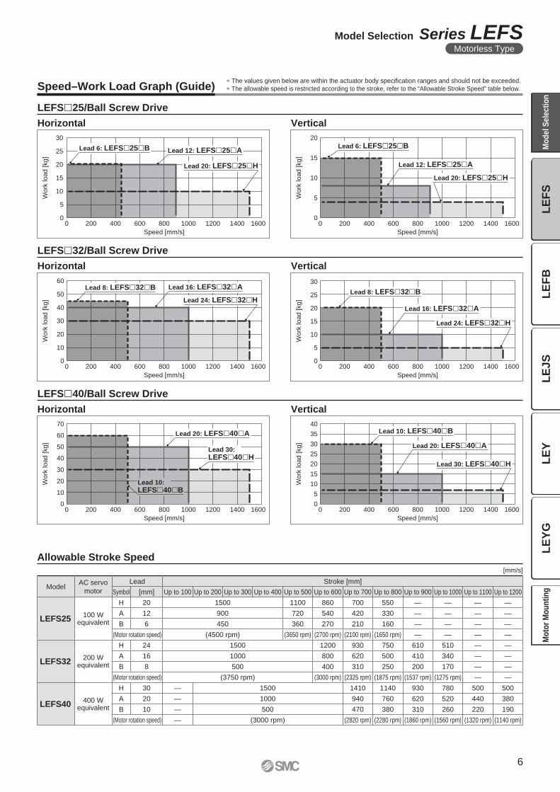
Speed–Work Load Graph (Guide)∗ The values given below are within the actuator body specifi cation ranges and should not be exceeded.
∗ The allowable speed is restricted according to the stroke, refer to the “Allowable Stroke Speed” table below.
LEFS�25/Ball Screw Drive
LEFS�40/Ball Screw Drive
LEFS�32/Ball Screw Drive
Horizontal Vertical
Horizontal Vertical
Horizontal Vertical
Allowable Stroke Speed[mm/s]
ModelAC servo
motor
Lead Stroke [mm]
Symbol [mm] Up to 100 Up to 200 Up to 300 Up to 400 Up to 500 Up to 600 Up to 700 Up to 800 Up to 900 Up to 1000 Up to 1100 Up to 1200
LEFS25100 W
equivalent
H 20 1500 1100 860 700 550 — — — —
A 12 900 720 540 420 330 — — — —
B 6 450 360 270 210 160 — — — —
(Motor rotation speed) (4500 rpm) (3650 rpm) (2700 rpm) (2100 rpm) (1650 rpm) — — — —
LEFS32200 W
equivalent
H 24 1500 1200 930 750 610 510 — —
A 16 1000 800 620 500 410 340 — —
B 8 500 400 310 250 200 170 — —
(Motor rotation speed) (3750 rpm) (3000 rpm) (2325 rpm) (1875 rpm) (1537 rpm) (1275 rpm) — —
LEFS40400 W
equivalent
H 30 — 1500 1410 1140 930 780 500 500
A 20 — 1000 940 760 620 520 440 380
B 10 — 500 470 380 310 260 220 190
(Motor rotation speed) — (3000 rpm) (2820 rpm) (2280 rpm) (1860 rpm) (1560 rpm) (1320 rpm) (1140 rpm)
6
Model Selection Series LEFSMotorless Type
LE
FS
LE
FB
LE
JS
LE
YL
EY
GM
od
el
Se
lec
tio
nM
oto
r M
ou
nti
ng
0
2500
5000
7500
10000
12500
15000
17500
20000
0 2 4 6 8 10
Work load [kg]
Accele
ration/D
ecele
ration [
mm
/s2] Duty ratio: 50 %
Duty ratio: 75 %
Duty ratio: 100 %
Work load [kg]A
ccele
ration/D
ecele
ration [
mm
/s2]
0
2500
5000
7500
10000
12500
15000
17500
20000
22500
0 1 2 3 4
Duty ratio: 50 %
Duty ratio: 75 %
Duty ratio: 100 %
Work load [kg]
Accele
ration/D
ecele
ration [
mm
/s2]
0
2500
5000
7500
10000
12500
15000
17500
20000
0 5 10 15 20
Duty ratio: 50 %
Duty ratio: 75 %
Duty ratio: 100 %
Work load [kg]
Accele
ration/D
ecele
ration [
mm
/s2]
0
2500
5000
7500
10000
12500
15000
17500
20000
0 5 10 15
Duty ratio: 50 %
Duty ratio: 75 %
Duty ratio: 100 %
Work load [kg]
Acce
lera
tio
n/D
ece
lera
tio
n [m
m/s
2]
0
2500
5000
7500
10000
12500
15000
17500
20000
0 2 4 6 8
Duty ratio: 50 %
Duty ratio: 75 %
Duty ratio: 100%
Work load [kg]
Acce
lera
tio
n/D
ece
lera
tio
n [m
m/s
2]
0
2500
5000
7500
10000
12500
15000
17500
20000
0 5 10 15 20
Duty ratio: 50 %
Duty ratio: 75 %
Duty ratio: 100 %
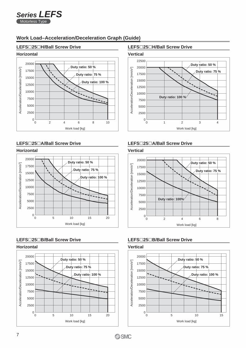
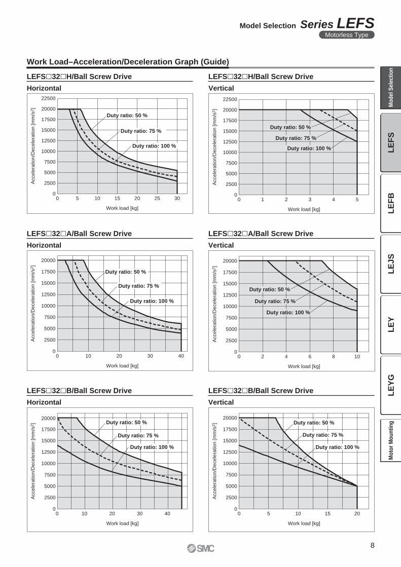
Work Load–Acceleration/Deceleration Graph (Guide)
Horizontal
Horizontal Vertical
LEFS�25�H/Ball Screw Drive
Horizontal Vertical
LEFS�25�A/Ball Screw Drive LEFS�25�A/Ball Screw Drive
LEFS�25�B/Ball Screw Drive LEFS�25�B/Ball Screw Drive
LEFS�25�H/Ball Screw Drive
Vertical
7
Series LEFSMotorless Type
Work load [kg]
Acce
lera
tio
n/D
ece
lera
tio
n [
mm
/s2]
2500
5000
7500
10000
12500
15000
17500
20000
22500
5 10 15 20 25 300
0
Duty ratio: 50 %
Duty ratio: 75 %
Duty ratio: 100 %
Work load [kg]A
ccele
ration/D
ecele
ration [
mm
/s2]
0
2500
5000
7500
10000
12500
15000
17500
20000
22500
1 2 3 4 50
Duty ratio: 50 %
Duty ratio: 75 %
Duty ratio: 100 %
0
2500
5000
7500
10000
12500
15000
17500
20000
0 10 20 30 40
Work load [kg]
Acce
lera
tio
n/D
ece
lera
tio
n [
mm
/s2] Duty ratio: 50 %
Duty ratio: 75 %
Duty ratio: 100 %
Work load [kg]
Accele
ration/D
ecele
ration [
mm
/s2]
0
2500
5000
7500
10000
12500
15000
17500
20000
0 5 10 15 20
Duty ratio: 50 %
Duty ratio: 75 %
Duty ratio: 100 %
Work load [kg]
Acce
lera
tio
n/D
ece
lera
tio
n [m
m/s
2]
0
2500
5000
7500
10000
12500
15000
17500
20000
0 2 4 6 8 10
Duty ratio: 50 %
Duty ratio: 75 %
Duty ratio: 100 %
Work load [kg]
Acce
lera
tio
n/D
ece
lera
tio
n [m
m/s
2]
0
2500
5000
7500
10000
12500
15000
17500
20000
0 10 20 30 40
Duty ratio: 50 %
Duty ratio: 75 %
Duty ratio: 100 %
Work Load–Acceleration/Deceleration Graph (Guide)
Horizontal
Horizontal Vertical
LEFS�32�H/Ball Screw Drive
Horizontal Vertical
LEFS�32�A/Ball Screw Drive LEFS�32�A/Ball Screw Drive
LEFS�32�B/Ball Screw Drive LEFS�32�B/Ball Screw Drive
LEFS�32�H/Ball Screw Drive
Vertical
8
Model Selection Series LEFSMotorless Type
LE
FS
LE
FB
LE
JS
LE
YL
EY
GM
od
el
Se
lec
tio
nM
oto
r M
ou
nti
ng
Work load [kg]
Accele
ration/D
ecele
ration [
mm
/s2]
2500
5000
7500
10000
12500
15000
17500
20000
22500
0 5 10 15 20 25 300
Duty ratio: 50 %
Duty ratio: 75 %
Duty ratio: 100 %
Work load [kg]A
ccele
ration/D
ecele
ration [
mm
/s2]
0
2500
5000
7500
10000
12500
15000
17500
20000
22500
0 1 2 3 4 5 6 7
Duty ratio: 50 %
Duty ratio: 75 %
Duty ratio: 100 %
Work load [kg]
Acce
lera
tion/D
ecele
ration [
mm
/s2]
0
2500
5000
7500
10000
12500
15000
17500
20000
22500
0 10 20 30 40 50 60
Duty ratio: 50 %
Duty ratio: 75 %
Duty ratio: 100 %
Work load [kg]
Accele
ration/D
ecele
ration [
mm
/s2]
0
2500
5000
7500
10000
12500
15000
17500
20000
22500
0 10 20 30
Duty ratio: 50 %
Duty ratio: 75 %
Duty ratio: 100 %
Work load [kg]
Acce
lera
tio
n/D
ece
lera
tio
n [m
m/s
2]
0
7500
10000
12500
15000
17500
20000
22500
0 10 20 30 40 50
2500
5000
Duty ratio: 50 %
Duty ratio: 75 %
Duty ratio: 100 %
Work load [kg]
Acce
lera
tio
n/D
ece
lera
tio
n [m
m/s
2]
0
2500
5000
7500
10000
12500
15000
17500
20000
22500
0 5 10 15
Duty ratio: 50 %
Duty ratio: 75 %
Duty ratio: 100 %
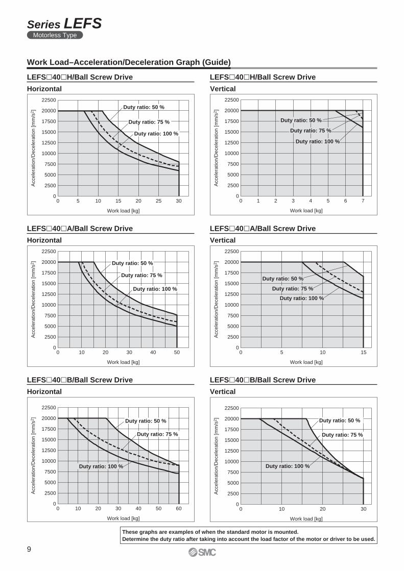
Work Load–Acceleration/Deceleration Graph (Guide)
Horizontal
Horizontal Vertical
LEFS�40�H/Ball Screw Drive
Horizontal Vertical
LEFS�40�A/Ball Screw Drive LEFS�40�A/Ball Screw Drive
LEFS�40�B/Ball Screw Drive LEFS�40�B/Ball Screw Drive
LEFS�40�H/Ball Screw Drive
Vertical
These graphs are examples of when the standard motor is mounted.
Determine the duty ratio after taking into account the load factor of the motor or driver to be used.
9
Series LEFSMotorless Type
L1
L3
Mep
m
L5
Mey
m
L4
Mer
m
L2
L6
0 10 20 30 40 50 60
Work load [kg]
L1
[m
m]
0
500
1500
1000
0 10 20 30 40
Work load [kg]
L1
[m
m]
0
500
1500
1000
0 5 10 15 20
Work load [kg]
L1
[m
m]
0
500
1500
1000
0 10 20 30 40 50 60
Work load [kg]
L3 [
mm
]
0
500
1500
1000
0 10 20 30 40
Work load [kg]
L3 [
mm
]
0
500
1500
1000
0 5 10 15 20
Work load [kg]
L3 [
mm
]
0
500
1500
1000
0 10 20 30 40 50 60
Work load [kg]
L4 [
mm
]
0
500
1500
1000
0 10 20 30 40
Work load [kg]
L4 [
mm
]
0
500
1500
1000
0 5 10 15 20
Work load [kg]
L4 [
mm
]
0
500
1500
1000
0 10 20 30 40 50 60
Work load [kg]
L5
[m
m]
0
500
1500
1000
0 10 20 30 40
Work load [kg]
L5
[m
m]
0
500
1500
1000
0 5 10 15 20
Work load [kg]
L5
[m
m]
0
500
1500
1000
0 10 20 30 40 50 60
Work load [kg]
L2
[m
m]
0 10 20 30 40
Work load [kg]
L2
[m
m]
0 5 10 15 20
Work load [kg]
L2
[m
m]
0
600
400
200
1000
800
0
600
400
200
1000
800
0
600
400
200
1000
800
0 10 20 30 40 50 60
Work load [kg]
L6 [m
m]
0 10 20 30 40
Work load [kg]
L6 [m
m]
0 5 10 15 20
Work load [kg]
L6 [m
m]
0
600
400
200
1000
800
0
600
400
200
1000
800
0
600
400
200
1000
800
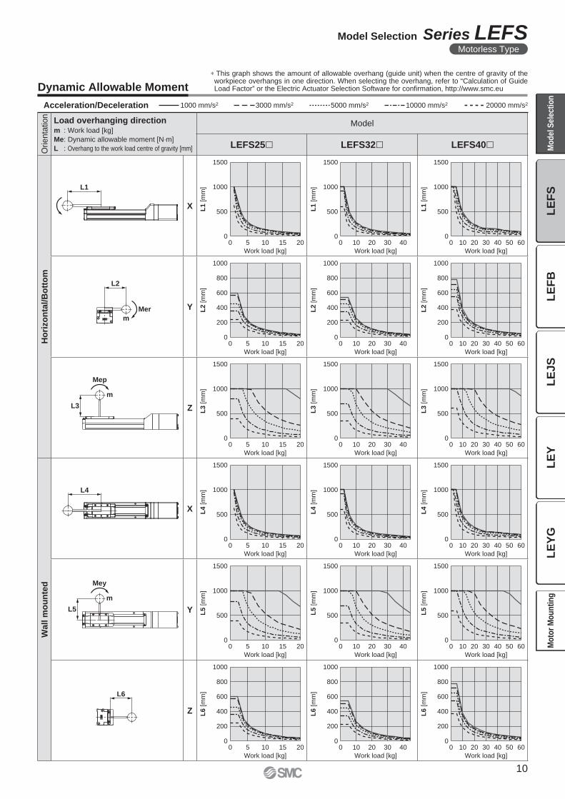
Dynamic Allowable Moment
∗ This graph shows the amount of allowable overhang (guide unit) when the centre of gravity of the workpiece overhangs in one direction. When selecting the overhang, refer to “Calculation of Guide Load Factor” or the Electric Actuator Selection Software for confi rmation, http://www.smc.eu
Acceleration/Deceleration 1000 mm/s2 3000 mm/s2 5000 mm/s2 10000 mm/s2 20000 mm/s2
Orienta
tion
Load overhanging directionm : Work load [kg]
Me: Dynamic allowable moment [N·m]
L : Overhang to the work load centre of gravity [mm]
Model
LEFS25� LEFS32� LEFS40�
Ho
rizo
nta
l/B
ott
om
X
Y
Z
Wall m
ou
nte
d
X
Y
Z
10
Model Selection Series LEFSMotorless Type
LE
FS
LE
FB
LE
JS
LE
YL
EY
GM
od
el
Se
lec
tio
nM
oto
r M
ou
nti
ng
xy
z
x z
y
xy
z
x
z y
0 10 20 30 40 50 60
Work load [kg]
L7
[m
m]
500
1500
1000
0 10 20 30 40
Work load [kg]
L7
[m
m]
500
1500
1000
0 5 10 2015
Work load [kg]
L7
[m
m]
0
500
1500
1000
0 10 20 30
Work load [kg]
L8
[m
m]
500
1500
1000
0 5 10 15 20
Work load [kg]
L8
[m
m]
500
1500
1000
0 4 62 8 10
Work load [kg]
L8
[m
m]
500
1500
1000
0 0
0 0 0
L7
Mep
m
L8
Mey
m
0 10 20 30 40 50 600
500
1500
1000
Lx
L1 [m
m]
Work load [kg]
0 10 20 30 40 50 600
600
400
200
1000
800
L2 [m
m]
Work load [kg]
Ly
0 10 20 30 40 50 600
500
1500
1000
L3 [m
m]
Work load [kg]
Lz
Orienta
tion
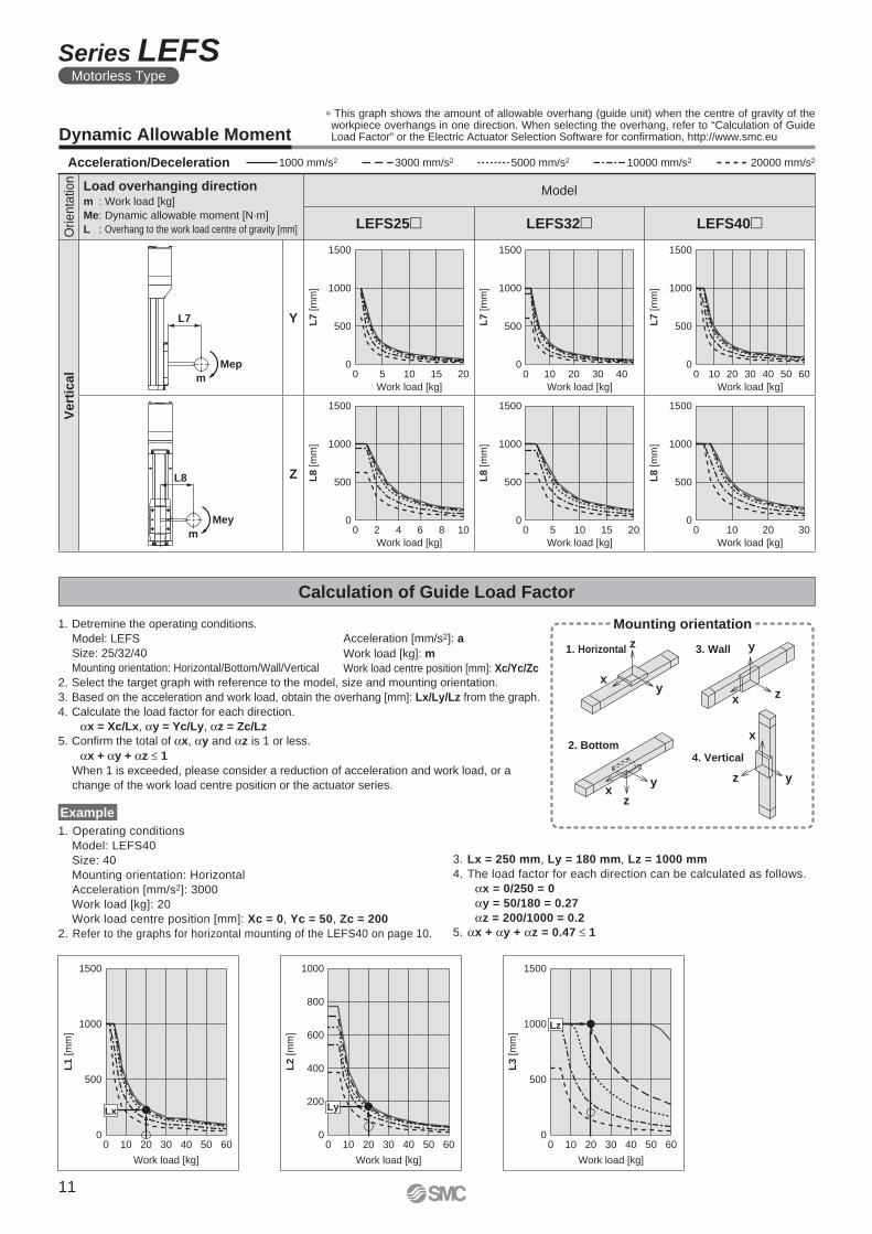
Load overhanging directionm : Work load [kg]
Me: Dynamic allowable moment [N·m]
L : Overhang to the work load centre of gravity [mm]
Model
LEFS25� LEFS32� LEFS40�
Ve
rtic
al
Y
Z
Acceleration/Deceleration 1000 mm/s2 3000 mm/s2 5000 mm/s2 10000 mm/s2 20000 mm/s2
Dynamic Allowable Moment
∗ This graph shows the amount of allowable overhang (guide unit) when the centre of gravity of the workpiece overhangs in one direction. When selecting the overhang, refer to “Calculation of Guide Load Factor” or the Electric Actuator Selection Software for confi rmation, http://www.smc.eu
Acceleration [mm/s2]: a
Work load [kg]: m
Work load centre position [mm]: Xc/Yc/Zc
1. Detremine the operating conditions.
Model: LEFS
Size: 25/32/40
Mounting orientation: Horizontal/Bottom/Wall/Vertical
2. Select the target graph with reference to the model, size and mounting orientation.
3. Based on the acceleration and work load, obtain the overhang [mm]: Lx/Ly/Lz from the graph.
4. Calculate the load factor for each direction.
αx = Xc/Lx, αy = Yc/Ly, αz = Zc/Lz
5. Confi rm the total of αx, αy and αz is 1 or less.
αx + αy + αz ≤ 1
When 1 is exceeded, please consider a reduction of acceleration and work load, or a
change of the work load centre position or the actuator series.
Mounting orientation
1. Horizontal 3. Wall
2. Bottom4. Vertical
1. Operating conditions
Model: LEFS40
Size: 40
Mounting orientation: Horizontal
Acceleration [mm/s2]: 3000
Work load [kg]: 20
Work load centre position [mm]: Xc = 0, Yc = 50, Zc = 200
2. Refer to the graphs for horizontal mounting of the LEFS40 on page 10.
3. Lx = 250 mm, Ly = 180 mm, Lz = 1000 mm
4. The load factor for each direction can be calculated as follows.
αx = 0/250 = 0
αy = 50/180 = 0.27
αz = 200/1000 = 0.2
5. αx + αy + αz = 0.47 ≤ 1
Calculation of Guide Load Factor
Example
11
Series LEFSMotorless Type
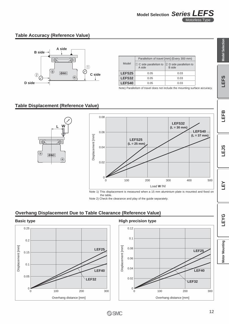
A side
C side
B side
D side
WL
Dis
pla
ce
me
nt
[mm
]
Load W [N]
LEFS25 (L = 25 mm)
LEFS40 (L = 37 mm)
LEFS32 (L = 30 mm)
0.08
0.06
0.04
0.02
00 100 200 300 400 500
LEF25
LEF32
LEF40
0
0.05
0.1
0.15
0.2
0.25
0 100 200 300
Dis
pla
cem
ent [m
m]
Overhang distance [mm]
Dis
pla
cem
ent [m
m]
0
0.02
0.04
0.06
0.08
0.1
0.12
0 100 200 300
Overhang distance [mm]
LEF25
LEF32
LEF40
Table Accuracy (Reference Value)
Overhang Displacement Due to Table Clearance (Reference Value)
Note 1) This displacement is measured when a 15 mm aluminium plate is mounted and fi xed on
the table.
Note 2) Check the clearance and play of the guide separately.
Note) Parallelism of travel does not include the mounting surface accuracy.
Table Displacement (Reference Value)
Model
Parallelism of travel [mm] (Every 300 mm)
q C side parallelism to A side
w D side parallelism to B side
LEFS25 0.05 0.03
LEFS32 0.05 0.03
LEFS40 0.05 0.03
Basic type High precision type
12
Model Selection Series LEFSMotorless Type
LE
FS
LE
FB
LE
JS
LE
YL
EY
GM
od
el
Se
lec
tio
nM
oto
r M
ou
nti
ng
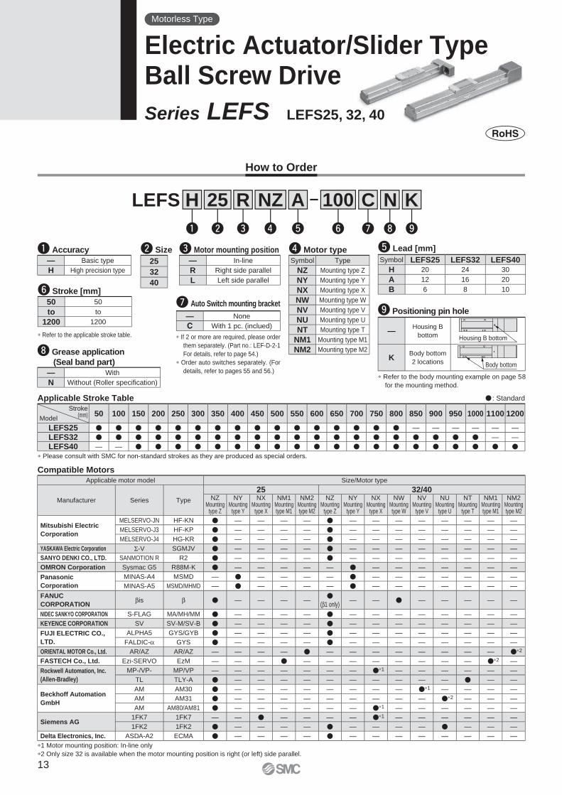
How to Order
� : Standard
Compatible Motors
Applicable Stroke TableStroke
(mm)Model
50 100 150 200 250 300 350 400 450 500 550 600 650 700 750 800 850 900 950 1000 1100 1200
LEFS25 � � � � � � � � � � � � � � � � — — — — — —
LEFS32 � � � � � � � � � � � � � � � � � � � � — —
LEFS40 — — � � � � � � � � � � � � � � � � � � � �
Motorless Type
Electric Actuator/Slider TypeBall Screw Drive
Series LEFS LEFS25, 32, 40
LEFS 100A25
w r t u i o
H R
q e y
NZ
∗ Please consult with SMC for non-standard strokes as they are produced as special orders.
∗ If 2 or more are required, please order
them separately. (Part no.: LEF-D-2-1
For details, refer to page 54.)
∗ Order auto switches separately. (For
details, refer to pages 55 and 56.)∗ Refer to the body mounting example on page 58
for the mounting method.
∗1 Motor mounting position: In-line only
∗2 Only size 32 is available when the motor mounting position is right (or left) side parallel.
t Lead [mm]
Symbol LEFS25 LEFS32 LEFS40
H 20 24 30
A 12 16 20
B 6 8 10
q Accuracy
— Basic type
H High precision type
y Stroke [mm]
∗ Refer to the applicable stroke table.
50 50
to to
1200 1200
i Grease application
(Seal band part)
o Positioning pin holeu Auto Switch mounting bracket
— With
N Without (Roller specification)
—Housing B
bottom Housing B bottom
KBody bottom
2 locations Body bottom
— None
C With 1 pc. (inclued)
r Motor type
Symbol Type
NZ Mounting type Z
NY Mounting type Y
NX Mounting type X
NW Mounting type W
NV Mounting type V
NU Mounting type U
NT Mounting type T
NM1 Mounting type M1
NM2 Mounting type M2
e Motor mounting position
— In-line
R Right side parallel
L Left side parallel
w Size
25
32
40
Applicable motor model Size/Motor type
Manufacturer Series Type
25 32/40NZ
Mountingtype Z
NYMounting
type Y
NXMounting
type X
NM1Mountingtype M1
NM2Mountingtype M2
NZMounting
type Z
NYMounting
type Y
NXMounting
type X
NWMountingtype W
NVMounting
type V
NUMounting
type U
NTMounting
type T
NM1Mountingtype M1
NM2Mountingtype M2
Mitsubishi Electric
Corporation
MELSERVO-JN HF-KN � — — — — � — — — — — — — —
MELSERVO-J3 HF-KP � — — — — � — — — — — — — —
MELSERVO-J4 HG-KR � — — — — � — — — — — — — —
YASKAWA Electric Corporation Σ-V SGMJV � — — — — � — — — — — — — —
SANYO DENKI CO., LTD. SANMOTION R R2 � — — — — � — — — — — — — —
OMRON Corporation Sysmac G5 R88M-K � — — — — — � — — — — — — —
Panasonic
Corporation
MINAS-A4 MSMD — � — — — — � — — — — — — —
MINAS-A5 MSMD/MHMD — � — — — — � — — — — — — —
FANUC
CORPORATIONβis β � — — — —
�(β1 only)
— — � — — — — —
NIDEC SANKYO CORPORATION S-FLAG MA/MH/MM � — — — — � — — — — — — — —
KEYENCE CORPORATION SV SV-M/SV-B � — — — — � — — — — — — — —
FUJI ELECTRIC CO.,
LTD.
ALPHA5 GYS/GYB � — — — — � — — — — — — — —
FALDIC-α GYS � — — — — � — — — — — — — —
ORIENTAL MOTOR Co., Ltd. AR/AZ AR/AZ — — — — � — — — — — — — — �∗2
FASTECH Co., Ltd. Ezi-SERVO EzM — — — � — — — — — — — — �∗2 —
Rockwell Automation, Inc.
(Allen-Bradley)
MP-/VP- MP/VP — — — — — — — �∗1 — — — — — —
TL TLY-A � — — — — — — — — — — � — —
Beckhoff Automation
GmbH
AM AM30 � — — — — — — — — �∗1 — — — —
AM AM31 � — — — — — — — — — �∗2 — — —
AM AM80/AM81 � — — — — — — �∗1 — — — — — —
Siemens AG1FK7 1FK7 — — � — — — — �∗1 — — — — — —
1FK2 1FK2 � — — — — � — — — — � — — —
Delta Electronics, Inc. ASDA-A2 ECMA � — — — — � — — — — — — — —
C N K
13
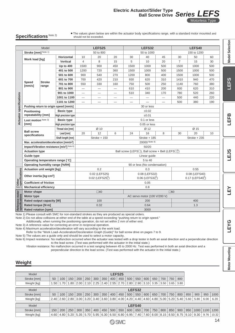
Specifi cations Note 2)
Weight
Note 1) Please consult with SMC for non-standard strokes as they are produced as special orders.
Note 2) Do not allow collisions at either end of the table at a speed exceeding “pushing return to origin speed.”
Additionally, when running the positioning operation, do not set within 2 mm of either end.
Note 3) A reference value for correcting an error in reciprocal operation.
Note 4) Maximum acceleration/deceleration will vary according to the work load.
Refer to the “Work Load–Acceleration/Deceleration Graph (Guide)” for ball screw drive on pages 7 to 9.
Note 5) The values are a guide only and should be used to select a motor capacity.
Note 6) Impact resistance: No malfunction occurred when the actuator was tested with a drop tester in both an axial direction and a perpendicular direction
to the lead screw. (Test was performed with the actuator in the initial state.)
Vibration resistance: No malfunction occurred in a test ranging between 45 to 2000 Hz. Test was performed in both an axial direction and a
perpendicular direction to the lead screw. (Test was performed with the actuator in the initial state.)
Model LEFS25 LEFS32 LEFS40
Actu
ato
r sp
ecifi
cati
on
s
Stroke [mm] Note 1) 50 to 800 50 to 1000 150 to 1200
Work load [kg]Horizontal 10 20 20 30 40 45 30 50 60
Vertical 4 8 15 5 10 20 7 15 30
Speed
[mm/s]
Stroke
range
Up to 400 1500 900 450 1500 1000 500 1500 1000 500
401 to 500 1200 720 360 1500 1000 500 1500 1000 500
501 to 600 900 540 270 1200 800 400 1500 1000 500
601 to 700 700 420 210 930 620 310 1410 940 470
701 to 800 550 330 160 750 500 250 1140 760 380
801 to 900 — — — 610 410 200 930 620 310
901 to 1000 — — — 510 340 170 780 520 260
1001 to 1100 — — — — — — 500 440 220
1101 to 1200 — — — — — — 500 380 190
Pushing return to origin speed [mm/s] 30 or less
Positioning
repeatability [mm]
Basic type ±0.02
High precision type ±0.01
Lost motion Note 3)
[mm]
Basic type 0.1 or less
High precision type 0.05 or less
Ball screw
specifi cations
Thread size [mm] Ø 10 Ø 12 Ø 15
Lead [mm] 20 12 6 24 16 8 30 20 10
Shaft length [mm] Stroke + 150 Stroke + 185 Stroke + 235
Max. acceleration/deceleration [mm/s2] 20000 Note 4)
Impact/Vibration resistance [m/s2] Note 6) 50/20
Actuation type Ball screw (LEFS�), Ball screw + Belt (LEFS�R L)
Guide type Linear guide
Operating temperature range [°C] 5 to 40
Operating humidity range [%RH] 90 or less (No condensation)
Oth
er
sp
ecifi
cati
on
s Actuation unit weight [kg] 0.2 0.3 0.55
Other inertia [kg·cm2]0.02 (LEFS25)
0.02 (LEFS25R L)
0.08 (LEFS32)
0.06 (LEFS32R L)
0.08 (LEFS40)
0.17 (LEFS40R L)
Coeffi cient of friction 0.05
Mechanical effi ciency 0.8
Refe
ren
ce m
oto
rsp
ecifi
cati
on
s
Motor shape �40 �60
Motor type AC servo motor (100 V/200 V)
Rated output capacity [W] 100 200 400
Rated torque [N·m] 0.32 0.64 1.3
Rated rotation [rpm] 3000
Model LEFS25
Stroke [mm] 50 100 150 200 250 300 350 400 450 500 550 600 650 700 750 800
Weight [kg] 1.50 1.70 1.80 2.00 2.10 2.25 2.40 2.55 2.70 2.80 2.90 3.10 3.35 3.50 3.65 3.80
Model LEFS40
Stroke [mm] 150 200 250 300 350 400 450 500 550 600 650 700 750 800 850 900 950 1000 1100 1200
Weight [kg] 4.60 4.80 5.20 5.35 5.70 5.95 6.30 6.50 6.80 6.95 7.40 7.60 8.00 8.15 8.50 8.75 9.10 9.30 9.76 10.32
Model LEFS32
Stroke [mm] 50 100 150 200 250 300 350 400 450 500 550 600 650 700 750 800 850 900 950 1000
Weight [kg] 2.40 2.60 2.80 3.00 3.20 3.40 3.60 3.80 4.00 4.20 4.40 4.60 4.80 5.00 5.20 5.40 5.60 5.80 6.00 6.20
¡The values given below are within the actuator body specifi cations range, with a standard motor mounted and
should not be exceeded.
Note 5)
14
Electric Actuator/Slider TypeBall Screw Drive Series LEFS
Motorless Type
LE
FS
LE
FB
LE
JS
LE
YL
EY
GM
od
el
Se
lec
tio
nM
oto
r M
ou
nti
ng
(102)
64
45
38
3H9 ( )
depth 3
3.5
4 x M5 x 0.8
thread depth 8.5
Body mounting
reference plane Note)
L
A (Table travel distance) 52 31.5 FF
47
48
38.5 Motor
Motor mount
10 (52)
(48)
24
57.8
38
6.5
6M4 x 0.7
thread depth 8
(F.G. terminal)
3H9 ( )
depth 34
n x Ø 4.5
10F
120
D x 120 (= E)
B
48
4 x FA thread
thread depth FB
45°
50
Motor mating part:Ø FD, depth FE
Mounting pitch: Ø FC
Motor mating part:Ø FD, depth FE
4 x Ø FA through hole
FG depth of counterbore FH∗ Spot facing is on the reverse side.
Mounting pitch: �FCØ 3H9 ( )
depth 3
+0.0250
+0.0250
+0.0250
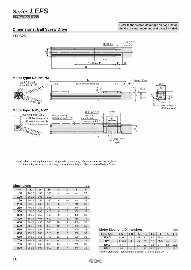
Dimensions [mm]
Motor Mounting Dimensions [mm]
Dimensions: Ball Screw Drive
LEFS25
Refer to the “Motor Mounting” on page 29 for
details of motor mounting and parts included.
Note) When mounting the actuator using the body mounting reference plane, set the height of
the mating surface or positioning pins to 3 mm minimun. (Recommended height 5 mm)
∗ Dimensions after mounting a ring spacer (Refer to page 29.)
Motor type: NM1, NM2
Motor type: NZ, NY, NX
Stroke L A B n D E F
50 201.5 56 160 4 — — 20
100 251.5 106 210 4 — — 35
150 301.5 156 260 4 — — 35
200 351.5 206 310 6 2 240 35
250 401.5 256 360 6 2 240 35
300 451.5 306 410 8 3 360 35
350 501.5 356 460 8 3 360 35
400 551.5 406 510 8 3 360 35
450 601.5 456 560 10 4 480 35
500 651.5 506 610 10 4 480 35
550 701.5 556 660 12 5 600 35
600 751.5 606 710 12 5 600 35
650 801.5 656 760 12 5 600 35
700 851.5 706 810 14 6 720 35
750 901.5 756 860 14 6 720 35
800 951.5 806 910 16 7 840 35
Motor type FA FB FC FD FE FF FG FH
NZ/NX M4 x 0.7 8 46 30 3.5 35.5 — —
NY M3 x 0.5 8 45 30 3.5 35.5 — —
NM1 3.4 — 31 22∗ 2.5∗ 24 6.5 13.5
NM2 3.4 — 31 22∗ 2.5∗ 33.1 6.5 22.6
15
Series LEFSMotorless Type
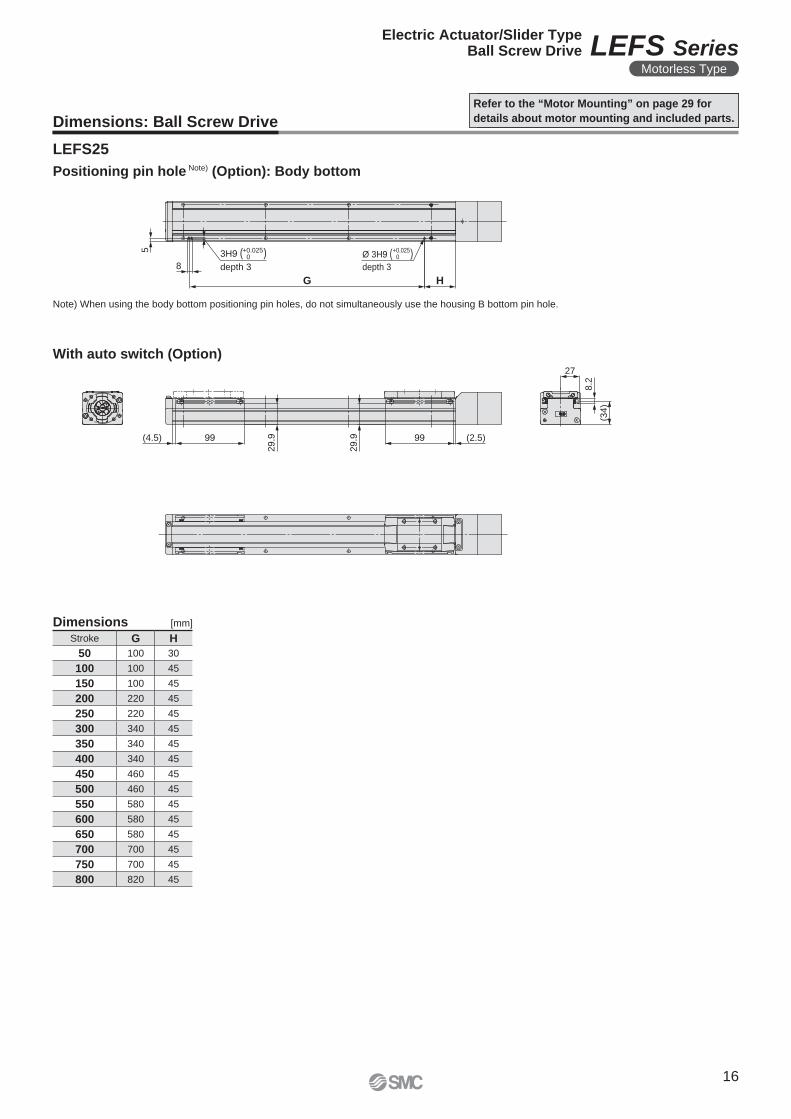
5
8
G H
+0.0250
+0.02503H9 ( )
depth 3
Ø 3H9 ( )depth 3
27
8.2
(34
)
(4.5) 99
29.9
29.9 99 (2.5)
Dimensions: Ball Screw Drive
Refer to the “Motor Mounting” on page 29 for
details about motor mounting and included parts.
Dimensions [mm]
LEFS25
Note) When using the body bottom positioning pin holes, do not simultaneously use the housing B bottom pin hole.
Stroke G H
50 100 30
100 100 45
150 100 45
200 220 45
250 220 45
300 340 45
350 340 45
400 340 45
450 460 45
500 460 45
550 580 45
600 580 45
650 580 45
700 700 45
750 700 45
800 820 45
Positioning pin hole Note) (Option): Body bottom
With auto switch (Option)
16
Electric Actuator/Slider TypeBall Screw Drive LEFS Series
Motorless Type
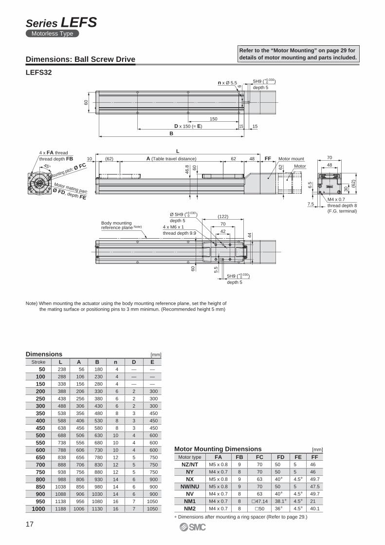
Motor mating part:Ø FD, depth FE
Mounting pitch: Ø FC Motor
Motor mount
(122)
44
70
424 x M6 x 1
thread depth 9.9
5H9 ( )
depth 5
5.560
62
FF4862A (Table travel distance)
L
10 (62)
46.8 60
B
D x 150 (= E)
150
1515
n x Ø 5.5
6
5H9 ( )
depth 560
(62)
30
70
48
6.5
7.5M4 x 0.7
thread depth 8
(F.G. terminal)
45°
4 x FA thread
thread depth FB
+0.0300
+0.0300
Ø 5H9 ( )
depth 5
+0.0300
Body mountingreference plane Note)
Motor Mounting Dimensions [mm]
Motor type FA FB FC FD FE FF
NZ/NT M5 x 0.8 9 70 50 5 46
NY M4 x 0.7 8 70 50 5 46
NX M5 x 0.8 9 63 40∗ 4.5∗ 49.7
NW/NU M5 x 0.8 9 70 50 5 47.5
NV M4 x 0.7 8 63 40∗ 4.5∗ 49.7
NM1 M4 x 0.7 8 �47.14 38.1∗ 4.5∗ 21
NM2 M4 x 0.7 8 �50 36∗ 4.5∗ 40.1
Dimensions: Ball Screw Drive
Refer to the “Motor Mounting” on page 29 for
details of motor mounting and parts included.
LEFS32
Note) When mounting the actuator using the body mounting reference plane, set the height of
the mating surface or positioning pins to 3 mm minimun. (Recommended height 5 mm)
Dimensions [mm]
Stroke L A B n D E
50 238 56 180 4 — —
100 288 106 230 4 — —
150 338 156 280 4 — —
200 388 206 330 6 2 300
250 438 256 380 6 2 300
300 488 306 430 6 2 300
350 538 356 480 8 3 450
400 588 406 530 8 3 450
450 638 456 580 8 3 450
500 688 506 630 10 4 600
550 738 556 680 10 4 600
600 788 606 730 10 4 600
650 838 656 780 12 5 750
700 888 706 830 12 5 750
750 938 756 880 12 5 750
800 988 806 930 14 6 900
850 1038 856 980 14 6 900
900 1088 906 1030 14 6 900
950 1138 956 1080 16 7 1050
1000 1188 1006 1130 16 7 1050
∗ Dimensions after mounting a ring spacer (Refer to page 29.)
17
Series LEFSMotorless Type
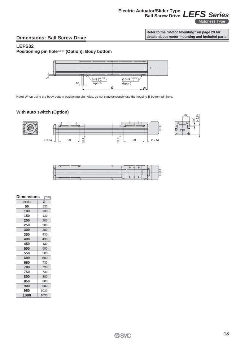
5
10
G 25
+0.03005H9 ( )
depth 5
Ø 5H9 ( )depth 5
+0.0300
32
(42
.5)
8.2
(14.5) 99
38.4
38.4 99 (12.5)
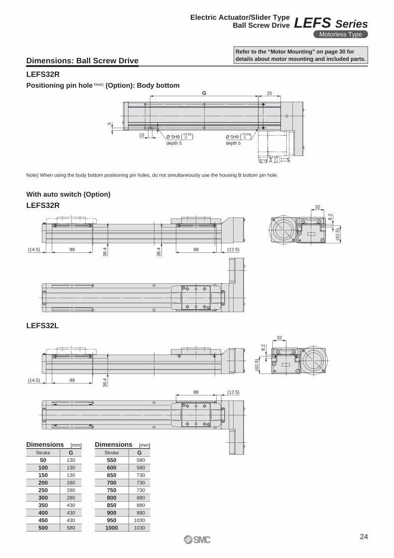
Dimensions: Ball Screw Drive
Refer to the “Motor Mounting” on page 29 for
details about motor mounting and included parts.
LEFS32
Dimensions [mm]
Stroke G
50 130
100 130
150 130
200 280
250 280
300 280
350 430
400 430
450 430
500 580
550 580
600 580
650 730
700 730
750 730
800 880
850 880
900 880
950 1030
1000 1030
Note) When using the body bottom positioning pin holes, do not simultaneously use the housing B bottom pin hole.
Positioning pin hole Note) (Option): Body bottom
With auto switch (Option)
18
Electric Actuator/Slider TypeBall Screw Drive LEFS Series
Motorless Type
106
58
(170)
4 x M8 x 1.25
thread depth 1360
7
90
61
(68)
318
8M4 x 0.7
thread depth 8
(F.G. terminal)
13 (86)
53.8 68
A (Table travel distance) 86 48 FF
L
67.5
Motor
76
B
D x 150 (= E) 60 15
150
7
6H9 ( )
depth 7
6H9 ( )
depth 6
n x Ø 6.6
4 x FA thread
thread depth FB
Motor mating part:Ø FD, depth FE
45°
Mounting pitch: Ø FC
74
Motor mount
+0.0300
Ø 6H9 ( )
depth 7
+0.0300
+0.0300
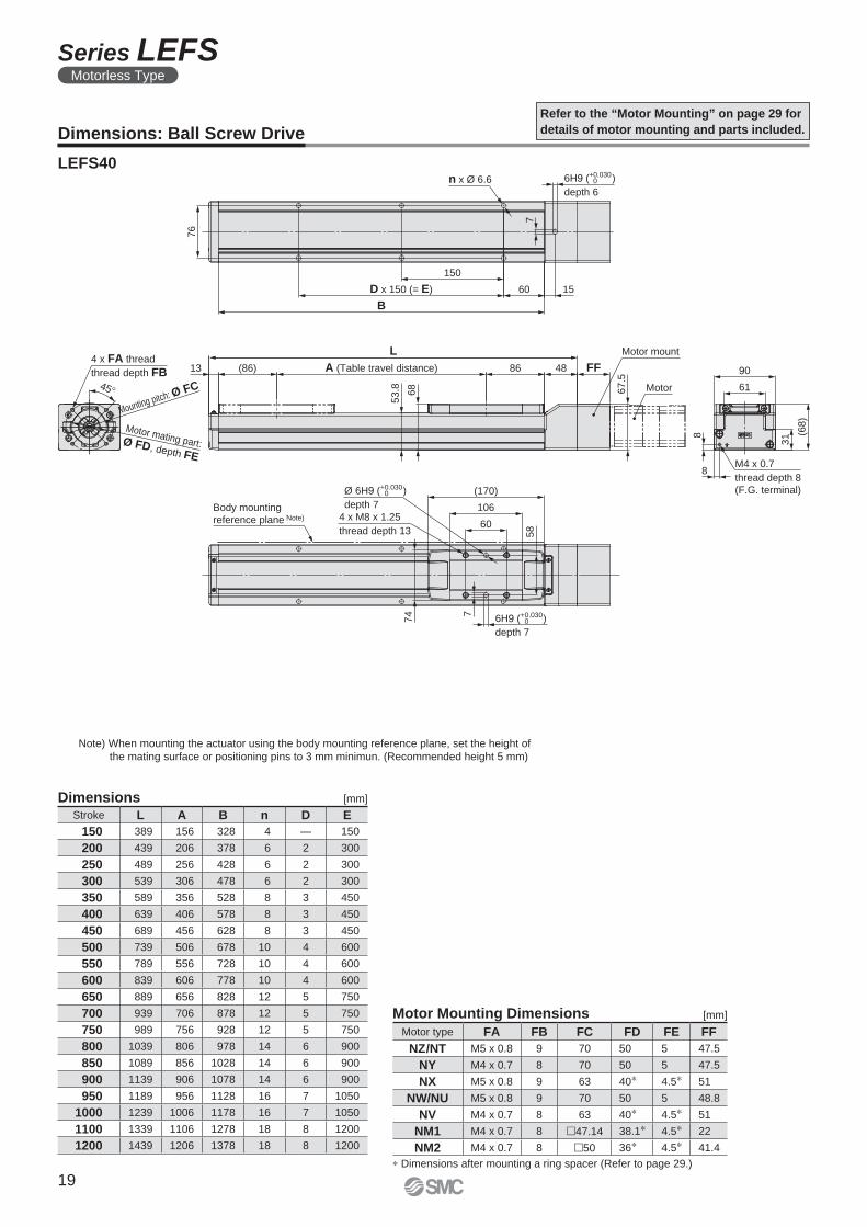
Body mounting
reference plane Note)
Motor type FA FB FC FD FE FF
NZ/NT M5 x 0.8 9 70 50 5 47.5
NY M4 x 0.7 8 70 50 5 47.5
NX M5 x 0.8 9 63 40∗ 4.5∗ 51
NW/NU M5 x 0.8 9 70 50 5 48.8
NV M4 x 0.7 8 63 40∗ 4.5∗ 51
NM1 M4 x 0.7 8 �47.14 38.1∗ 4.5∗ 22
NM2 M4 x 0.7 8 �50 36∗ 4.5∗ 41.4
Dimensions: Ball Screw Drive
LEFS40
Refer to the “Motor Mounting” on page 29 for
details of motor mounting and parts included.
Note) When mounting the actuator using the body mounting reference plane, set the height of
the mating surface or positioning pins to 3 mm minimun. (Recommended height 5 mm)
Motor Mounting Dimensions [mm]
Dimensions [mm]
∗ Dimensions after mounting a ring spacer (Refer to page 29.)
Stroke L A B n D E
150 389 156 328 4 — 150
200 439 206 378 6 2 300
250 489 256 428 6 2 300
300 539 306 478 6 2 300
350 589 356 528 8 3 450
400 639 406 578 8 3 450
450 689 456 628 8 3 450
500 739 506 678 10 4 600
550 789 556 728 10 4 600
600 839 606 778 10 4 600
650 889 656 828 12 5 750
700 939 706 878 12 5 750
750 989 756 928 12 5 750
800 1039 806 978 14 6 900
850 1089 856 1028 14 6 900
900 1139 906 1078 14 6 900
950 1189 956 1128 16 7 1050
1000 1239 1006 1178 16 7 1050
1100 1339 1106 1278 18 8 1200
1200 1439 1206 1378 18 8 1200
19
Series LEFSMotorless Type
7
11
G 70
+0.03006H9 ( )
depth 6
Ø 6H9 ( )depth 6
+0.0300
(48)
8.2
38.5
(38.5) 99
43.9
43.9 99 (36.5)
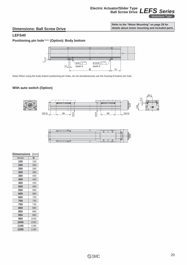
Dimensions: Ball Screw Drive
Refer to the “Motor Mounting” on page 29 for
details about motor mounting and included parts.
LEFS40
Note) When using the body bottom positioning pin holes, do not simultaneously use the housing B bottom pin hole.
Positioning pin hole Note) (Option): Body bottom
Dimensions [mm]
Stroke G
150 130
200 280
250 280
300 280
350 430
400 430
450 430
500 580
550 580
600 580
650 730
700 730
750 730
800 880
850 880
900 880
950 1030
1000 1030
1100 1180
1200 1180
With auto switch (Option)
20
Electric Actuator/Slider TypeBall Screw Drive LEFS Series
Motorless Type
3.5
6.5 M4 x 0.7
thread depth 8
(F.G. terminal)6
38
.5 48
4
FF 18.5 (2.4)
10
6
38
Motor flange
Motor
3H9 (+0.025 +0 )
depth 3
4 x M5 x 0.8
thread depth 8.5
Body mounting
reference plane Note)
(102)
64
45
50
(52) A (Table travel distance)
L
10 52 40.5
Motor side stroke end
2 x FA
thread depth FB
FF
FE
Ø F
D
�FJ
FF
Ø F
D
FC
�42
FC
2 x Ø FA
Counterbore diameter FG,
depth FH
n x Ø 4.5
120
D x 120 (= E)
B
G
10
48
(48
)
24
38
58
F
3H9 (+0.025 +0 )
depth 3
45
° Mounting pitch: Ø FC
Ø 3H9 (+0.025 +0 )
depth 3
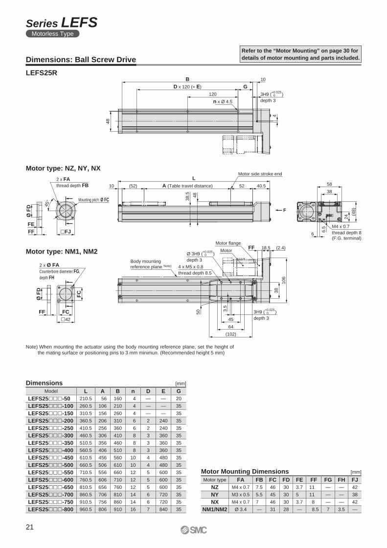
Dimensions: Ball Screw Drive
LEFS25R
Refer to the “Motor Mounting” on page 30 for
details of motor mounting and parts included.
Dimensions [mm]
Model L A B n D E G
LEFS25���-50 210.5 56 160 4 — — 20
LEFS25���-100 260.5 106 210 4 — — 35
LEFS25���-150 310.5 156 260 4 — — 35
LEFS25���-200 360.5 206 310 6 2 240 35
LEFS25���-250 410.5 256 360 6 2 240 35
LEFS25���-300 460.5 306 410 8 3 360 35
LEFS25���-350 510.5 356 460 8 3 360 35
LEFS25���-400 560.5 406 510 8 3 360 35
LEFS25���-450 610.5 456 560 10 4 480 35
LEFS25���-500 660.5 506 610 10 4 480 35
LEFS25���-550 710.5 556 660 12 5 600 35
LEFS25���-600 760.5 606 710 12 5 600 35
LEFS25���-650 810.5 656 760 12 5 600 35
LEFS25���-700 860.5 706 810 14 6 720 35
LEFS25���-750 910.5 756 860 14 6 720 35
LEFS25���-800 960.5 806 910 16 7 840 35
Motor type FA FB FC FD FE FF FG FH FJ
NZ M4 x 0.7 7.5 46 30 3.7 11 — — 42
NY M3 x 0.5 5.5 45 30 5 11 — — 38
NX M4 x 0.7 7 46 30 3.7 8 — — 42
NM1/NM2 Ø 3.4 — 31 28 — 8.5 7 3.5 —
Motor Mounting Dimensions [mm]
Note) When mounting the actuator using the body mounting reference plane, set the height of
the mating surface or positioning pins to 3 mm minimun. (Recommended height 5 mm)
Motor type: NM1, NM2
Motor type: NZ, NY, NX
21
Series LEFSMotorless Type
5 10
G 25
Ø 5H9 ( )depth 5
+0.0300
5H9 ( )depth 5
+0.0300
27
(34)
8.2
99(4.5)
29.9
29.9 99 (2.5)
27
8.2
(34)
29.999(4.5)
(2.5)99
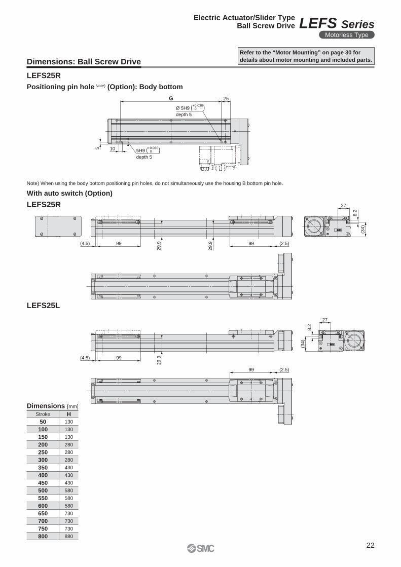
Dimensions: Ball Screw Drive
Refer to the “Motor Mounting” on page 30 for
details about motor mounting and included parts.
LEFS25R
LEFS25R
LEFS25L
Note) When using the body bottom positioning pin holes, do not simultaneously use the housing B bottom pin hole.
Positioning pin hole Note) (Option): Body bottom
Dimensions [mm]
Stroke H
50 130
100 130
150 130
200 280
250 280
300 280
350 430
400 430
450 430
500 580
550 580
600 580
650 730
700 730
750 730
800 880
With auto switch (Option)
22
Electric Actuator/Slider TypeBall Screw Drive LEFS Series
Motorless Type
46.8 6
3
3
6.5
7.5
M4 x 0.7
thread depth 8
(F.G. terminal)
5.5
Ø 5H9 (+0.030 +0 )
depth 8 (depth of counterbore 3)
5H9 (+0.030 +0 )
depth 8 (depth of counterbore 3)
5H9 (+0.030 +0 )
depth 5
Motor flange(2.4)22.5FFMotor
4 x M6 x 1
thread depth 12.5 (depth of counterbore 3)132.5
44
(122)
70
42
Body mounting reference plane Note)
60 CC
48
70
(63
)
30
A (Table travel distance) 62 55(62)10
LMotor side stroke end
2 x FA
thread depth FB
Ø F
D
FE
FF �60
60
D x 150 (= E)
B
150
n x Ø 5.5
6
15
15
FF
Ø F
D
FC
�FJ
FC
Mounting pitch: Ø FC
45
°
F
2 x (M4 x 0.7)
thread depth FH
2 x FA
thread depth FB
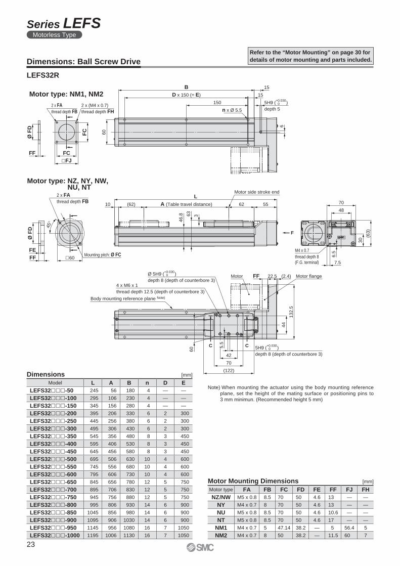
Dimensions: Ball Screw Drive
LEFS32R
Refer to the “Motor Mounting” on page 30 for
details of motor mounting and parts included.
Dimensions [mm]
Model L A B n D E
LEFS32���-50 245 56 180 4 — —
LEFS32���-100 295 106 230 4 — —
LEFS32���-150 345 156 280 4 — —
LEFS32���-200 395 206 330 6 2 300
LEFS32���-250 445 256 380 6 2 300
LEFS32���-300 495 306 430 6 2 300
LEFS32���-350 545 356 480 8 3 450
LEFS32���-400 595 406 530 8 3 450
LEFS32���-450 645 456 580 8 3 450
LEFS32���-500 695 506 630 10 4 600
LEFS32���-550 745 556 680 10 4 600
LEFS32���-600 795 606 730 10 4 600
LEFS32���-650 845 656 780 12 5 750
LEFS32���-700 895 706 830 12 5 750
LEFS32���-750 945 756 880 12 5 750
LEFS32���-800 995 806 930 14 6 900
LEFS32���-850 1045 856 980 14 6 900
LEFS32���-900 1095 906 1030 14 6 900
LEFS32���-950 1145 956 1080 16 7 1050
LEFS32���-1000 1195 1006 1130 16 7 1050
Note) When mounting the actuator using the body mounting reference
plane, set the height of the mating surface or positioning pins to
3 mm minimun. (Recommended height 5 mm)
Motor type: NM1, NM2
Motor type: NZ, NY, NW, NU, NT
Motor type FA FB FC FD FE FF FJ FH
NZ/NW M5 x 0.8 8.5 70 50 4.6 13 — —
NY M4 x 0.7 8 70 50 4.6 13 — —
NU M5 x 0.8 8.5 70 50 4.6 10.6 — —
NT M5 x 0.8 8.5 70 50 4.6 17 — —
NM1 M4 x 0.7 5 47.14 38.2 — 5 56.4 5
NM2 M4 x 0.7 8 50 38.2 — 11.5 60 7
Motor Mounting Dimensions [mm]
23
Series LEFSMotorless Type
5
10
G 25
Ø 5H9 ( )depth 5
+0.030Ø 5H9 ( )
depth 5
+0.030
32
8.2
(42.5
)
(14.5) 99
38.4
38.4 99 (12.5)
32
8.2
(42.5
)
(14.5) 99
38.4
99 (12.5)
Dimensions: Ball Screw Drive
Refer to the “Motor Mounting” on page 30 for
details about motor mounting and included parts.
LEFS32R
LEFS32R
LEFS32L
Note) When using the body bottom positioning pin holes, do not simultaneously use the housing B bottom pin hole.
Positioning pin hole Note) (Option): Body bottom
Stroke G
50 130
100 130
150 130
200 280
250 280
300 280
350 430
400 430
450 430
500 580
Stroke G
550 580
600 580
650 730
700 730
750 730
800 880
850 880
900 880
950 1030
1000 1030
Dimensions Dimensions[mm] [mm]
With auto switch (Option)
24
Electric Actuator/Slider TypeBall Screw Drive LEFS Series
Motorless Type
6H9 (+0.030 +0 )
depth 6
6H9 (+0.030 +0 )
depth 7
Ø 6H9 (+0.030 +0 )
depth 7
15
3
58
(2.4)28FFMotor flangeMotor
4 x M8 x 1.25
thread depth 13
Body mounting
reference plane Note)
(170)
106
60
7
62.486A (Table travel distance)
LMotor side stroke end
68
53
.8
(86)13
68
31
90
61
8
8
M4 x 0.7
thread depth 8
(F.G. terminal)
74
7
15
60
n x Ø 6.6
150
D x 150 (= E)
B
76
Ø F
D
FF
FE
�60
Mounting pitch: Ø FC
4 x FA
thread depth FB
45
°
F
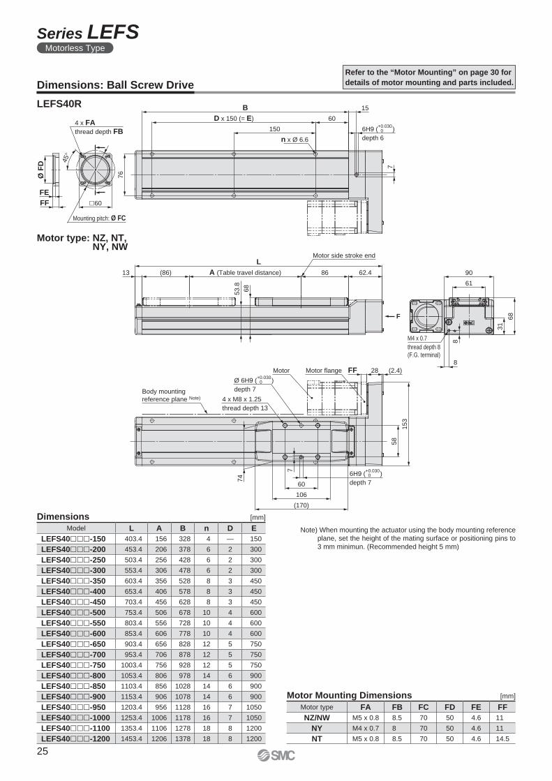
Dimensions: Ball Screw Drive
LEFS40R
Refer to the “Motor Mounting” on page 30 for
details of motor mounting and parts included.
Dimensions [mm]
Model L A B n D E
LEFS40���-150 403.4 156 328 4 — 150
LEFS40���-200 453.4 206 378 6 2 300
LEFS40���-250 503.4 256 428 6 2 300
LEFS40���-300 553.4 306 478 6 2 300
LEFS40���-350 603.4 356 528 8 3 450
LEFS40���-400 653.4 406 578 8 3 450
LEFS40���-450 703.4 456 628 8 3 450
LEFS40���-500 753.4 506 678 10 4 600
LEFS40���-550 803.4 556 728 10 4 600
LEFS40���-600 853.4 606 778 10 4 600
LEFS40���-650 903.4 656 828 12 5 750
LEFS40���-700 953.4 706 878 12 5 750
LEFS40���-750 1003.4 756 928 12 5 750
LEFS40���-800 1053.4 806 978 14 6 900
LEFS40���-850 1103.4 856 1028 14 6 900
LEFS40���-900 1153.4 906 1078 14 6 900
LEFS40���-950 1203.4 956 1128 16 7 1050
LEFS40���-1000 1253.4 1006 1178 16 7 1050
LEFS40���-1100 1353.4 1106 1278 18 8 1200
LEFS40���-1200 1453.4 1206 1378 18 8 1200
Note) When mounting the actuator using the body mounting reference
plane, set the height of the mating surface or positioning pins to
3 mm minimun. (Recommended height 5 mm)
Motor type: NZ, NT, NY, NW
Motor type FA FB FC FD FE FF
NZ/NW M5 x 0.8 8.5 70 50 4.6 11
NY M4 x 0.7 8 70 50 4.6 11
NT M5 x 0.8 8.5 70 50 4.6 14.5
Motor Mounting Dimensions [mm]
25
Series LEFSMotorless Type
70G7 11 Ø 6H9 ( )
depth 6
+0.03006H9 ( )
depth 6
+0.0300
38.5
8.2
(48)
(38.5) 99
43.9
43.9 99 (36.5)
99 (36.5)
(48)
8.2
38.5
(38.5) 99
43.9
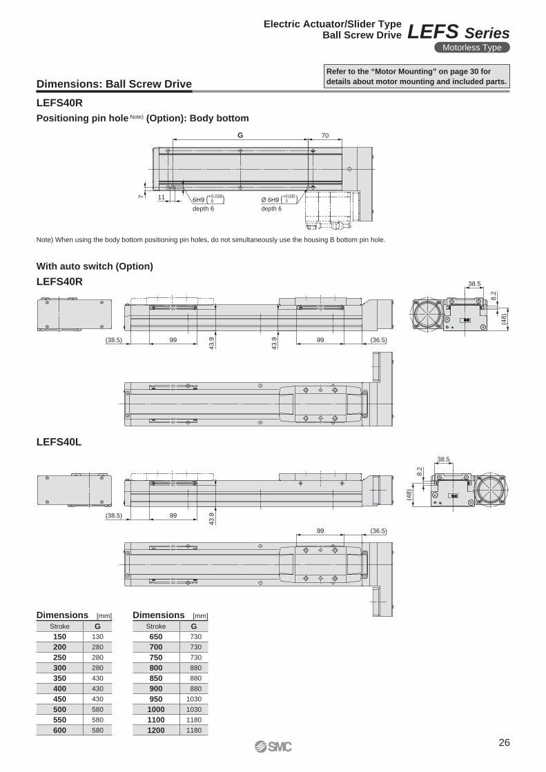
Dimensions: Ball Screw Drive
Refer to the “Motor Mounting” on page 30 for
details about motor mounting and included parts.
LEFS40R
LEFS40R
LEFS40L
Note) When using the body bottom positioning pin holes, do not simultaneously use the housing B bottom pin hole.
Positioning pin hole Note) (Option): Body bottom
Dimensions Dimensions[mm] [mm]
Stroke G
150 130
200 280
250 280
300 280
350 430
400 430
450 430
500 580
550 580
600 580
Stroke G
650 730
700 730
750 730
800 880
850 880
900 880
950 1030
1000 1030
1100 1180
1200 1180
With auto switch (Option)
26
Electric Actuator/Slider TypeBall Screw Drive LEFS Series
Motorless Type
Motor
[Provided by user]
Motor flange
Hexagon socket
head cap screw/MM
(Tightening torque: TT [N·m])
Motor side hub
Ø P
D
Mounting dimension: FPMotor mounting screw
[Provided by user]
Motor side hub
Motor flange
Hexagon socket
head set screw/MM
(Tightening torque: TT [N·m])
Motor
[Provided by user]
∗ Select D-shaped
shaft motor.
Motor mounting screw
[Provided by user]
Ø P
D
Mounting dimension: FP
Motor shaft
Hub
Hexagon socket head set screw
D-cut of the
motor shaft
Motor flange
Motor side hub
Motor mounting screw
Motor
Body side hub
Spider
Motor
Motor mounting screw
Ring spacer
Body side hub
Motor flange
Spider
Match the convex part of the motor hub to the
concave part of the spider on the body side hub.
Motor side hub
∗ For screw sizes, refer to the hub mounting
dimensions.
∗ For screw sizes, refer to the hub
mounting dimensions.
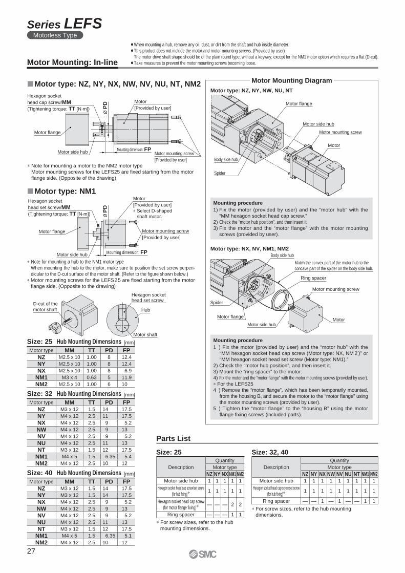
Motor Mounting Diagram
Motor Mounting: In-line
¡When mounting a hub, remove any oil, dust, or dirt from the shaft and hub inside diameter.
¡This product does not include the motor and motor mounting screws. (Provided by user)
The motor drive shaft shape should be of the plain round type, without a keyway; except for the NM1 motor option which requires a fl at (D-cut).
¡Take measures to prevent the motor mounting screws becoming loose.
Motor type: NX, NV, NM1, NM2
�Motor type: NM1
�Motor type: NZ, NY, NX, NW, NV, NU, NT, NM2Motor type: NZ, NY, NW, NU, NT
∗ Note for mounting a hub to the NM1 motor type
When mounting the hub to the motor, make sure to position the set screw perpen-
dicular to the D-cut surface of the motor shaft. (Refer to the fi gure shown below.)
∗ Motor mounting screws for the LEFS25 are fi xed starting from the motor
fl ange side. (Opposite to the drawing)
Parts List
Size: 25 Size: 32, 40
Mounting procedure
1) Fix the motor (provided by user) and the “motor hub” with the
“MM hexagon socket head cap screw.”
2) Check the “motor hub position”, and then insert it.
3) Fix the motor and the “motor flange” with the motor mounting
screws (provided by user).
Mounting procedure
1 ) Fix the motor (provided by user) and the “motor hub” with the
“MM hexagon socket head cap screw (Motor type: NX, NM 2 )” or
“MM hexagon socket head set screw (Motor type: NM1).”
2) Check the “motor hub position”, and then insert it.
3) Mount the “ring spacer” to the motor.
4) Fix the motor and the “motor fl ange” with the motor mounting screws (provided by user).
∗ For the LEFS25
4 ) Remove the “motor flange”, which has been temporarily mounted,
from the housing B, and secure the motor to the “motor fl ange” using
the motor mounting screws (provided by user).
5 ) Tighten the “motor flange” to the “housing B” using the motor
fl ange fi xing screws (included parts).
∗ Note for mounting a motor to the NM2 motor type
Motor mounting screws for the LEFS25 are fi xed starting from the motor
fl ange side. (Opposite of the drawing)
[mm]
Motor type MM TT PD FPNZ M2.5 x 10 1.00 8 12.4
NY M2.5 x 10 1.00 8 12.4
NX M2.5 x 10 1.00 8 6.9
NM1 M3 x 4 0.63 5 11.9
NM2 M2.5 x 10 1.00 6 10
Size: 25 Hub Mounting Dimensions
[mm]
Motor type MM TT PD FPNZ M3 x 12 1.5 14 17.5
NY M4 x 12 2.5 11 17.5
NX M4 x 12 2.5 9 5.2
NW M4 x 12 2.5 9 13
NV M4 x 12 2.5 9 5.2
NU M4 x 12 2.5 11 13
NT M3 x 12 1.5 12 17.5
NM1 M4 x 5 1.5 6.35 5.4
NM2 M4 x 12 2.5 10 12
Size: 32 Hub Mounting Dimensions
[mm]
Motor type MM TT PD FPNZ M3 x 12 1.5 14 17.5
NY M3 x 12 1.5 14 17.5
NX M4 x 12 2.5 9 5.2
NW M4 x 12 2.5 9 13
NV M4 x 12 2.5 9 5.2
NU M4 x 12 2.5 11 13
NT M3 x 12 1.5 12 17.5
NM1 M4 x 5 1.5 6.35 5.1
NM2 M4 x 12 2.5 10 12
Size: 40 Hub Mounting DimensionsDescription
Quantity
Motor type
NZ NY NX NW NV NU NT NM1 NM2Motor side hub 1 1 1 1 1 1 1 1 1
Hexagon socket head cap screw/set screw
(for hub fi xing)∗ 1 1 1 1 1 1 1 1 1
Ring spacer — — 1 — 1 — — 1 1
Description
Quantity
Motor type
NZ NY NX NM1 NM2Motor side hub 1 1 1 1 1
Hexagon socket head cap screw/set screw
(for hub fi xing)∗ 1 1 1 1 1
Hexagon socket head cap screw
(for motor fl ange fi xing)∗ — — — 2 2
Ring spacer — — — 1 1
27
Series LEFSMotorless Type
Ø P
D Mounting dimension:
FP
Timing belt
(Belt tension/tensile force: BT [N])
Cover plate
Round head combination screw/M3 x 6
(Tightening torque: 0.63 [N·m])
Hexagon socket head cap screw
(Tightening torque: 0.63 [N·m])
Motor flange
Motor side pulleyHexagon socket head cap screw/MM
(Tightening torque: TT [N·m])
Motor
[Provided by user]
Return plate
Timing belt
(Belt tension/tensile force: BT [N])
Cover plate
Round head combination screw/M3 x 6
(Tightening torque: 0.63 [N·m])
Hexagon socket head cap screw
(Tightening torque: 0.63 [N·m])
Motor mounting screw
[Provided by user]
Motor flange
Hexagon socket head set screw/MM
(Tightening torque: TT [N·m])
Motor
[Provided by user]
Ø P
D
Mounting dimension: FP
Motor side pulley
Return plate
Hexagon socket
head set screw
Hub
Motor shaft
D-cut of the motor shaft
Motor mounting screw
[Provided by user]
Motor flange
Motor side pulley
Cover plate
Timing belt
Body side pulley
Return plate
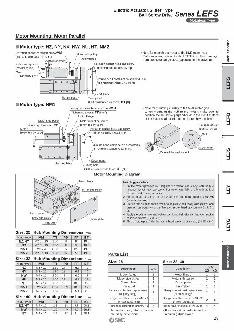
Motor Mounting: Motor Parallel
∗ For screw sizes, refer to the hub
mounting dimensions.
∗ For screw sizes, refer to the hub
mounting dimensions.
Description Q'ty
Motor flange 1
Motor side pulley 1
Cover plate 1
Timing belt 1
Hexagon socket head cap/set screw
(for pulley fixing)∗ 1
Hexagon socket head cap screw M3 x 8
(for motor flange fixing)2
Round head combination screw M3 x 6 4
DescriptionQ'ty
32 40Motor flange 1 1
Motor side pulley 1 1
Cover plate 1 1
Timing belt 1 1
Hexagon socket head cap/set screw
(for pulley fixing)∗ 1 1
Hexagon socket head cap screw M4 x 12
(for motor flange fixing)2 4
Round head combination screw M3 x 6 4 4
�Motor type: NM1
�Motor type: NZ, NY, NX, NW, NU, NT, NM2
∗ Note for mounting a pulley to the NM1 motor type
When mounting the hub to the motor, make sure to
position the set screw perpendicular to the D-cut surface
of the motor shaft. (Refer to the fi gure shown below.)
Mounting procedure
1) Fix the motor (provided by user) and the “motor side pulley” with the MM
hexagon socket head cap screw. For motor type “NM 1 ”, fix with the MM
hexagon socket head set screw.
2) Fix the motor and the “motor flange” with the motor mounting screws
(provided by user).
3) Put the “timing belt” on the “motor side pulley” and “body side pulley”, and
then fi x it temporarily with the “hexagon socket head cap screws ( 2 x M 3 x
8).”
4) Apply the belt tension and tighten the timing belt with the “hexagon socket
head cap screws (2 x M3 x 8).”
5) Fix the “return plate” with the “round head combination screws (4 x M3 x 6).”
Motor Mounting Diagram
Parts List
Size: 25 Size: 32, 40
∗ Note for mounting a motor to the NM2 motor type
Motor mounting screws for the LEFS25 are fi xed starting
from the motor fl ange side. (Opposite of the drawing)
[mm]
[mm]
[mm]
Motor type MM TT PD FP BTNZ/NY M2.5 x 10 1.00 8 8 19.6
NX M2.5 x 10 1.00 8 5 19.6
NM1 M3 x 4 0.63 5 12.5 19.6
NM2 M2.5 x 10 1.00 6 5.5 19.6
Motor type MM TT PD FP BTNZ M3 x 12 1.50 14 6.6 49
NY M3 x 12 1.50 11 6.6 49
NW M4 x 12 2.50 9 6.6 49
NU M3 x 12 1.50 11 4.2 49
NT M3 x 12 1.50 12 10.6 49
NM1 M3 x 4 0.63 6.35 10.6 49
NM2 M3 x 12 1.50 10 5.1 49
Motor type MM TT PD FP BTNZ/NY M4 x 12 2.5 14 4.5 98.1
NW M4 x 12 2.5 9 4.5 98.1
NT M4 x 12 2.5 12 8 98.1
Size: 25 Hub Mounting Dimensions
Size: 32 Hub Mounting Dimensions
Size: 40 Hub Mounting Dimensions
28
Electric Actuator/Slider TypeBall Screw Drive Series LEFS
Motorless Type
LE
FB
LE
JS
LE
YL
EF
SL
EY
GM
od
el
Se
lec
tio
nM
oto
r M
ou
nti
ng
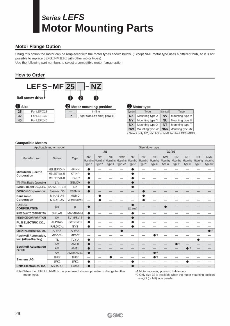
Motor Flange Option
NZMF 25SLEF
Ball screw drive
How to Order
Compatible Motors
Series LEFS
Motor Mounting Parts
q Size w Motor mounting position
q ew
25 For LEF�25
32 For LEF�32
40 For LEF�40
— In-line
P (Right side/Left side) parallel
e Motor type
Symbol Type
NZ Mounting type Z
NY Mounting type Y
NX Mounting type X
NW Mounting type W
Using this option the motor can be renplaced with the motor types shown below. (Except NM1 motor type uses a different hub, so it is not
possible to replace LEFS�NM1�-� with other motor types)
Use the following part numbers to select a compatible motor fl ange option.
Applicable motor model Size/Motor type
Manufacturer Series Type
25 32/40
NZ
Mounting
type Z
NY
Mounting
type Y
NX
Mounting
type X
NM2
Mounting
type M2
NZ
Mounting
type Z
NY
Mounting
type Y
NX
Mounting
type X
NW
Mounting
type W
NV
Mounting
type V
NU
Mounting
type U
NT
Mounting
type T
NM2
Mounting
type M2
Mitsubishi Electric
Corporation
MELSERVO-JN HF-KN � — — — � — — — — — — —
MELSERVO-J3 KF-KP � — — — � — — — — — — —
MELSERVO-J4 HG-KR � — — — � — — — — — — —
YASKAWA Electric Corporation Σ-V SGMJV � — — — � — — — — — — —
SANYO DENKI CO., LTD. SANMOTION R R2 � — — — � — — — — — — —
OMRON Corporation Sysmac G5 R88M-K � — — — — � — — — — — —
Panasonic
Corporation
MINAS-A4 MSMD — � — — — � — — — — — —
MINAS-A5 MSMD/MHMD — � — — — � — — — — — —
FANUC
CORPORATIONβis β � — — —
�(β1 only)
— — � — — — —
NIDEC SANKYO CORPORATION S-FLAG MA/MH/MM � — — — � — — — — — — —
KEYENCE CORPORATION SV SV-M/SV-B � — — — � — — — — — — —
FUJI ELECTRIC CO.,
LTD.
ALPHA5 GYS/GYB � — — — � — — — — — — —
FALDIC-α GYS � — — — � — — — — — — —
ORIENTAL MOTOR Co., Ltd. AR/AZ AR/AZ — — — � — — — — — — — �∗2
Rockwell Automation,
Inc. (Allen-Bradley)
MP-/VP- MP/VP — — — — — — �∗1 — — — — —
TL TLY-A � — — — — — — — — — � —
Beckhoff Automation
GmbH
AM AM30 � — — — — — — — �∗1 — — —
AM AM31 � — — — — — — — — �∗2 — —
AM AM80/AM81 � — — — — — �∗1 — — — — —
Siemens AG1FK7 1FK7 — — � — — — �∗1 — — — — —
1FK2 1FK2 � — — — � — — — — � — —
Delta Electronics, Inc. ASDA-A2 ECMA � — — — � — — — — — — —
∗ Select only NZ, NY, NX or NM2 for the LEFS-MF25.
Symbol Type
NV Mounting type V
NU Mounting type U
NT Mounting type T
NM2 Mounting type M2
∗1 Motor mounting position: In-line only
∗2 Only size 32 is available when the motor mounting position
is right (or left) side parallel.
Note) When the LEF���NM1�-� is purchased, it is not possible to change to other
motor types.
29
q werBody side hub, spider
Actuator (LEFS)
I.D
.: Ø
PD
M2 M1Motor
Motor mounting screw
t
Ø FD
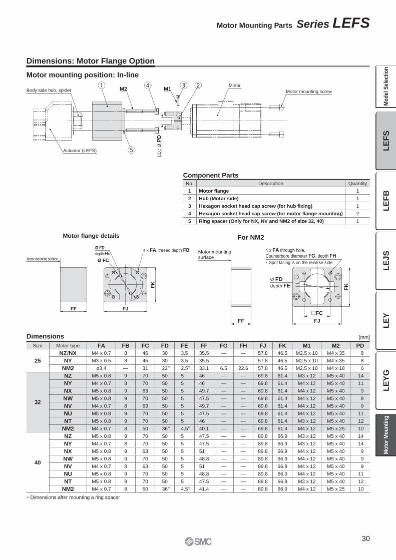
depth FE
Ø FC
4 x FA, thread depth FB
Motor mounting surface
FF FJ
FK
FF FJ
�FC
4 x FA through hole,
Counterbore diameter FG, depth FH
∗ Spot facing is on the reverse side.
Ø FD
depth FE
FK
Motor mounting surface
Motor fl ange details
Dimensions: Motor Flange Option
Dimensions [mm]
Motor mounting position: In-line
Size Motor type FA FB FC FD FE FF FG FH FJ FK M1 M2 PD
25
NZ/NX M4 x 0.7 8 46 30 3.5 35.5 — — 57.8 46.5 M2.5 x 10 M4 x 35 8
NY M3 x 0.5 8 45 30 3.5 35.5 — — 57.8 46.5 M2.5 x 10 M4 x 35 8
NM2 ø3.4 — 31 22∗ 2.5∗ 33.1 6.5 22.6 57.8 46.5 M2.5 x 10 M4 x 18 6
32
NZ M5 x 0.8 9 70 50 5 46 — — 69.8 61.4 M3 x 12 M5 x 40 14
NY M4 x 0.7 8 70 50 5 46 — — 69.8 61.4 M4 x 12 M5 x 40 11
NX M5 x 0.8 9 63 50 5 49.7 — — 69.8 61.4 M4 x 12 M5 x 40 9
NW M5 x 0.8 9 70 50 5 47.5 — — 69.8 61.4 M4 x 12 M5 x 40 9
NV M4 x 0.7 8 63 50 5 49.7 — — 69.8 61.4 M4 x 12 M5 x 40 9
NU M5 x 0.8 9 70 50 5 47.5 — — 69.8 61.4 M4 x 12 M5 x 40 11
NT M5 x 0.8 9 70 50 5 46 — — 69.8 61.4 M3 x 12 M5 x 40 12
NM2 M4 x 0.7 8 50 36∗ 4.5∗ 40.1 — — 69.8 61.4 M4 x 12 M5 x 25 10
40
NZ M5 x 0.8 9 70 50 5 47.5 — — 89.8 66.9 M3 x 12 M5 x 40 14
NY M4 x 0.7 8 70 50 5 47.5 — — 89.8 66.9 M3 x 12 M5 x 40 14
NX M5 x 0.8 9 63 50 5 51 — — 89.8 66.9 M4 x 12 M5 x 40 9
NW M5 x 0.8 9 70 50 5 48.8 — — 89.8 66.9 M4 x 12 M5 x 40 9
NV M4 x 0.7 8 63 50 5 51 — — 89.8 66.9 M4 x 12 M5 x 40 9
NU M5 x 0.8 9 70 50 5 48.8 — — 89.8 66.9 M4 x 12 M5 x 40 11
NT M5 x 0.8 9 70 50 5 47.5 — — 89.8 66.9 M3 x 12 M5 x 40 12
NM2 M4 x 0.7 8 50 36∗ 4.5∗ 41.4 — — 89.8 66.9 M4 x 12 M5 x 25 10
∗ Dimensions after mounting a ring spacer
Component PartsNo. Description Quantity
1 Motor flange 1
2 Hub (Motor side) 1
3 Hexagon socket head cap screw (for hub fixing) 1
4 Hexagon socket head cap screw (for motor flange mounting) 2
5 Ring spacer (Only for NX, NV and NM2 of size 32, 40) 1
For NM2
30
Motor Mounting Parts Series LEFS
LE
FB
LE
JS
LE
YL
EF
SL
EY
GM
od
el
Se
lec
tio
nM
oto
r M
ou
nti
ng
e w q r
Motor mounting screw
Motor M1
Ø P
D (
I.D
.)
M2
Actuator
�FJ
Ø FC
FA
thread depth FB
Ø F
D
FF
FE
Motor mounting surface
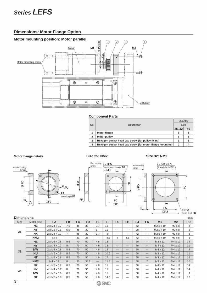
Dimensions: Motor Flange Option
Motor mounting position: Motor parallel
Motor fl ange details
Size Motor type FA FB FC FD FE FF FG FH FJ FK M1 M2 PD
25
NZ 2 x M4 x 0.7 7.5 46 30 3.7 11 — — 42 — M2.5 x 10 M3 x 8 8
NY 2 x M3 x 0.5 5.5 45 30 5 11 — — 38 — M2.5 x 10 M3 x 8 8
NX 2 x M4 x 0.7 7 46 30 3.7 8 — — 42 — M2.5 x 10 M3 x 8 8
NM2 ø3.4 — 31 28 — 8.5 7 3.5 42 — M2.5 x 10 M3 x 8 6
32
NZ 2 x M5 x 0.8 8.5 70 50 4.6 13 — — 60 — M3 x 12 M4 x 12 14
NY 2 x M4 x 0.7 8 70 50 4.6 13 — — 60 — M3 x 12 M4 x 12 11
NW 2 x M5 x 0.8 8.5 70 50 4.6 13 — — 60 — M4 x 12 M4 x 12 9
NU 2 x M5 x 0.8 8.5 70 50 4.6 10.6 — — 60 — M3 x 12 M4 x 12 11
NT 2 x M5 x 0.8 8.5 70 50 4.6 17 — — 60 — M3 x 12 M4 x 12 12
NM2 M4 x 0.7 8 50 38.2 — 11.5 — — 60 7 M3 x 12 M4 x 12 10
40
NZ 4 x M5 x 0.8 8.5 70 50 4.6 11 — — 60 — M4 x 12 M4 x 12 14
NY 4 x M4 x 0.7 8 70 50 4.6 11 — — 60 — M4 x 12 M4 x 12 14
NW 4 x M5 x 0.8 8.5 70 50 4.6 11 — — 60 — M4 x 12 M4 x 12 9
NT 4 x M5 x 0.8 8.5 70 50 4.6 14.5 — — 60 — M4 x 12 M4 x 12 12
Size 25: NM2 Size 32: NM2
Dimensions [mm]
Component Parts
No. Description
Quantity
Size
25, 32 40
1 Motor flange 1 1
2 Motor pulley 1 1
3 Hexagon socket head cap screw (for pulley fixing) 1 1
4 Hexagon socket head cap screw (for motor flange mounting) 2 4
�FJ
FC
FC
2 x øFA
Counterbore diameter FG,
depth FH
øF
D
FF
2 x (M4 x 0.7)
(thread depth FK)
Ø F
D
FC
FF2 x FA
thread depth FB�FJ
FC
Motor mounting surface
Motor mounting surface
31
Series LEFS
T1
a1 a2
L
Speed:
V [
mm
/s]
Time[s]
T2 T3 T4
L3
Mep
m
10
0
W
Speed: V [mm/s]
Wo
rk lo
ad
: W
[kg
]
0 1000 200015000
15
5
20
25
30LEFB40
LEFB25
LEFB32
0
500
1000
0 10 20 30 40 50 60
Work load [kg]
Overh
ang: L
3 [m
m]
100
1000 mm/s2
3000 mm/s2
5000 mm/s2
10000 mm/s2
20000mm/s2
¡Workpiece weight: 20 [kg]
¡Speed: 1500 [mm/s]
¡Acceleration/Deceleration: 3000 [mm/s2]
¡Stroke: 2000 [mm]
¡Mounting position: Horizontal
¡Workpiece mounting condition:
Check the work load–speed. <Speed–Work Load Graph>
Select a model based on the workpiece mass and speed, within the range of the actuator speci-
fi cations, while refering to the “Speed–Work Load Graph (Guide)” on page 33.
Selection example) The LEFB40�S-2000 is provisionally selected based on the graph on the right.
Check the cycle time.
Calculate the cycle time using the
following calculation method.
Cycle time:
T can be found from the following equation.
¡T4: Settling time varies depending
on the motor type and load. The
value below is recommended.
¡T2: Constant speed time can be
found from the following equation.
¡T1: Acceleration time and T3: Deceleration
time can be found from the following equation.
Check the guide moment.
Based on the above calculation result,
the LEFB40�S-2000 can be selected.
Calculation example)
T1 to T4 can be calculated as follows.
T1 = V/a1 = 1500/3000 = 0.5 [s],
T3 = V/a2 = 1500/3000 = 0.5 [s]
T4 = 0.05 [s]
Therefore, the cycle time can be
calculated as follows.
T = T1 + T2 + T3 + T4
= 0.5 + 0.83 + 0.5 + 0.05
= 1.88 [s]
∗ The conditions for the settling time vary depending on the motor or driver to be used.
Selection Procedure
Selection Example
Step 1 Check the work load–speed. Step 2 Check the cycle time. Step 3 Check the allowable moment.
Operating
conditions
Step 1
Step 2
T = T1 + T2 + T3 + T4 [s]
T1 = V/a1 [s] T3 = V/a2 [s]
T2 = [s] L − 0.5 · V · (T1 + T3)
V
T4 = 0.05 [s]
Step 3
L : Stroke [mm]
··· (Operating condition)
V : Speed [mm/s]
··· (Operating condition)
a1: Acceleration [mm/s2]
··· (Operating condition)
a2: Deceleration [mm/s2]
··· (Operating condition)
T1: Acceleration time [s]
Time until the set speed is reached
T2: Constant speed time [s]
Time when the actuator is operating
at a constant speed
T3: Deceleration time [s]
Time from the constant speed
operation until movement stops
T4: Settling time [s]
Time until positioning is completed
T2 =
=
= 0.83 [s]
L − 0.5 · V · (T1 + T3)
V
2000 − 0.5 · 1500 · (0.5 + 0.5)
1500
∗ Refer to the motor manufacturers catalogue for details os the regeneration resistance.
<Speed–Work Load Graph>
(LEFB40)
Motorless Type
Electric Actuator/Slider Type
Ball Screw Drive/Series LEFB
Model Selection
32
LE
FS
LE
FB
LE
JS
LE
YL
EY
GM
od
el
Se
lec
tio
nM
oto
r M
ou
nti
ng
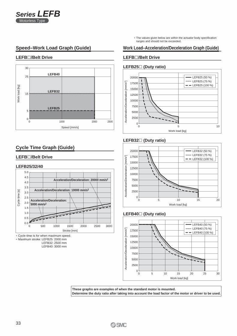
LEFB40
LEFB25
LEFB32
0 1000 2000 2500
Speed [mm/s]
0
5
15
25
30
Wo
rk lo
ad
[kg
]
0.0
0.5
1.0
1.5
2.0
2.5
3.0
3.5
4.0
4.5
5.0
Cycle
tim
e [s]
0 500 1000 1500 2000 2500 3000
Stroke [mm]
Acceleration/Deceleration: 10000 mm/s2
Acceleration/Deceleration: 20000 mm/s2
Acceleration/Deceleration:
5000 mm/s2
LEFB25 (50 %)
LEFB25 (75 %)
LEFB25 (100 %)
Acce
lera
tio
n/D
ece
lera
tio
n [m
m/s
2]
Work load [kg]
0 5 100
2500
5000
7500
10000
12500
15000
17500
20000
LEFB32 (50 %)
LEFB32 (75 %)
LEFB32 (100 %)
2500
5000
7500
10000
12500
15000
17500
20000
Accele
ration/D
ecele
ration [
mm
/s2]
0 5 10 15 20
Work load [kg]
0
LEFB40 (50 %)
LEFB40 (75 %)
LEFB40 (100 %)
Accele
ration/D
ecele
ration [m
m/s
2]
Work load [kg]
0
2500
5000
7500
10000
12500
15000
17500
20000
0 5 10 15 20 25 30
Speed–Work Load Graph (Guide) Work Load–Acceleration/Deceleration Graph (Guide)
LEFB�/Belt Drive
Cycle Time Graph (Guide)
LEFB�/Belt Drive
LEFB�/Belt Drive
LEFB32� (Duty ratio)
LEFB25� (Duty ratio)
LEFB40� (Duty ratio)
LEFB25/32/40
∗ The values given below are within the actuator body specifi cation
ranges and should not be exceeded.
These graphs are examples of when the standard motor is mounted.
Determine the duty ratio after taking into account the load factor of the motor or driver to be used.
∗ Cycle time is for when maximum speed.
∗ Maximum stroke: LEFB25: 2000 mm
LEFB32: 2500 mm
LEFB40: 3000 mm
33
Series LEFBMotorless Type
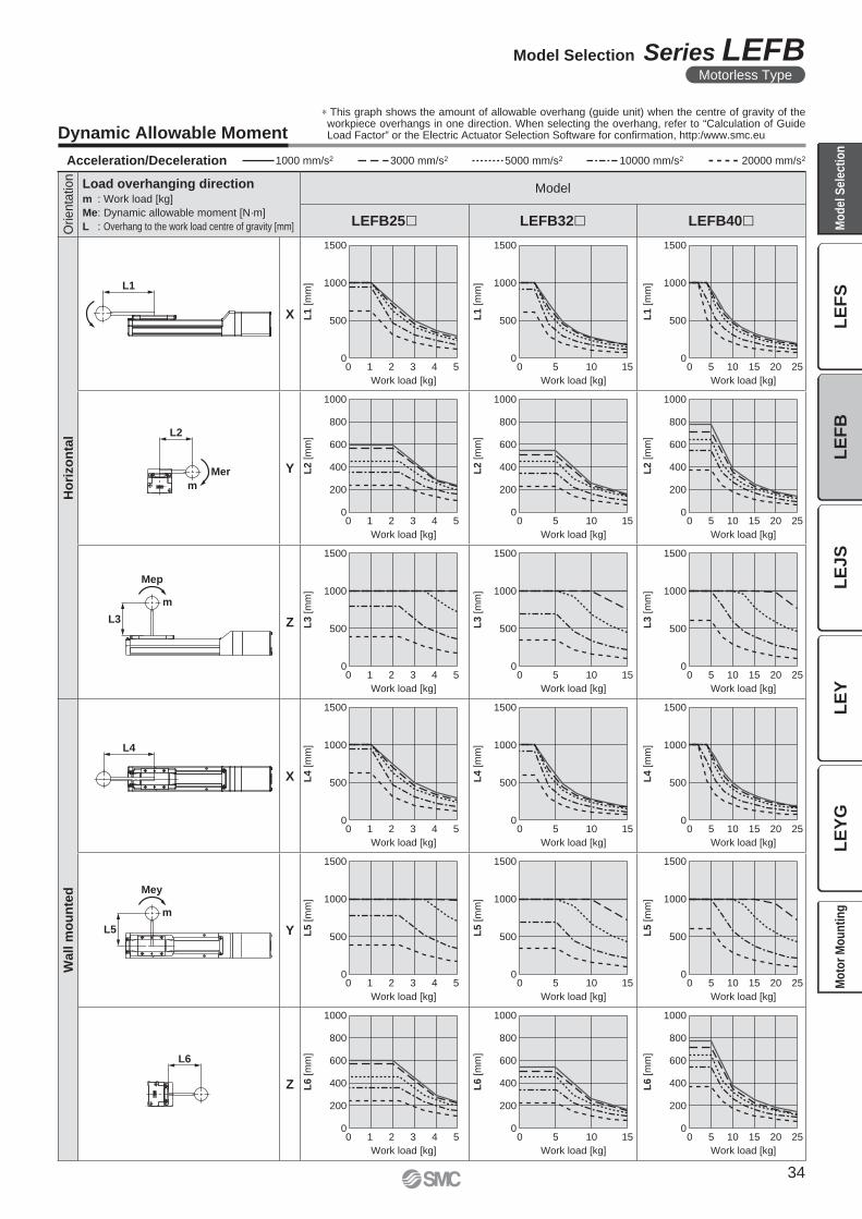
Work load [kg]
L1
[m
m]
Work load [kg]
L1
[m
m]
Work load [kg]
L1
[m
m]
Work load [kg]
L3
[m
m]
Work load [kg]
L3
[m
m]
Work load [kg]
L3
[m
m]
Work load [kg]
L4
[m
m]
Work load [kg]
L4
[m
m]
Work load [kg]
L4
[m
m]
Work load [kg]
L5
[m
m]
Work load [kg]
L5
[m
m]
Work load [kg]
L5
[m
m]
Work load [kg]
L2
[m
m]
Work load [kg]Work load [kg]
L2
[m
m]
L2
[m
m]
Work load [kg]
L6
[m
m]
Work load [kg]
L6
[m
m]
Work load [kg]
L6
[m
m]
0
200
400
600
800
1000
0
200
400
600
800
1000
0
200
400
600
800
1000
0
500
1000
1500
0
500
1000
1500
0
500
1000
1500
0 1 2 3 4 5
0 1 2 3 4 5
0 5 10 15
0 5 10 15
0 5 10 15 20 25
0 5 10 15 20 25
0
200
400
600
800
1000
0
200
400
600
800
1000
0
200
400
600
800
1000
0
500
1000
1500
0
500
1000
1500
0
500
1000
1500
0
500
1000
1500
0
500
1000
1500
0
500
1000
1500
0
500
1000
1500
0
500
1000
1500
0
500
1000
1500
0 1 2 3 4 5
0 1 2 3 4 5
0 1 2 3 4 5
0 5 10 15
0 5 10 15
0 5 10 15
0 5 10 15
0 5 10 15 20 25
0 5 10 15 20 25
0 5 10 15 20 25
0 5 10 15 20 250 1 2 3 4 5
L1
L3
Mep
m
L5
Mey
m
L4
Mer
m
L2
L6
Acceleration/Deceleration 1000 mm/s2 3000 mm/s2 5000 mm/s2 10000 mm/s2 20000 mm/s2
Dynamic Allowable Moment
Orienta
tion
Load overhanging directionm : Work load [kg]
Me: Dynamic allowable moment [N·m]
L : Overhang to the work load centre of gravity [mm]
Model
LEFB25� LEFB32� LEFB40�
Ho
rizo
nta
l
X
Y
Z
Wall m
ou
nte
d
X
Y
Z
∗ This graph shows the amount of allowable overhang (guide unit) when the centre of gravity of the workpiece overhangs in one direction. When selecting the overhang, refer to “Calculation of Guide Load Factor” or the Electric Actuator Selection Software for confi rmation, http:/www.smc.eu
34
Model Selection Series LEFBMotorless Type
LE
FS
LE
FB
LE
JS
LE
YL
EY
GM
od
el
Se
lec
tio
nM
oto
r M
ou
nti
ng
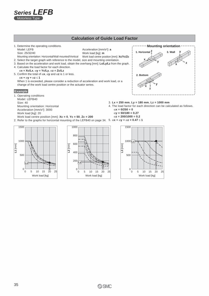
xy
z
x z
y
xy
z
0 5 10 15 20 250
500
1500
1000
Lx
L1 [m
m]
Work load [kg]
L2
[m
m]
Work load [kg]
0 5 10 15 20 250
600
400
200
1000
800
Ly
L3
[m
m]
Work load [kg]
0 5 10 15 20 250
500
1500
1000 Lz
Calculation of Guide Load Factor
Acceleration [mm/s2]: a
Work load [kg]: m
Work load centre position [mm]: Xc/Yc/Zc
1. Determine the operating conditions.
Model: LEFB
Size: 25/32/40
Mounting orientation: Horizontal/Wall mounted/Vertical
2. Select the target graph with reference to the model, size and mounting orientation.
3. Based on the acceleration and work load, obtain the overhang [mm]: Lx/Ly/Lz from the graph.
4. Calculate the load factor for each direction.
αx = Xc/Lx, αy = Yc/Ly, αz = Zc/Lz
5. Confi rm the total of αx, αy and αz is 1 or less.
αx + αy + αz ≤ 1
When 1 is exceeded, please consider a reduction of acceleration and work load, or a
change of the work load centre position or the actuator series.
Mounting orientation
1. Horizontal 3. Wall
2. Bottom
Example
1. Operating conditions
Model: LEFB40
Size: 40
Mounting orientation: Horizontal
Acceleration [mm/s2]: 3000
Work load [kg]: 20
Work load centre position [mm]: Xc = 0, Yc = 50, Zc = 200
2. Refer to the graphs for horizontal mounting of the LEFB40 on page 34.
3. Lx = 250 mm, Ly = 180 mm, Lz = 1000 mm
4. The load factor for each direction can be calculated as follows.
αx = 0/250 = 0
αy = 50/180 = 0.27
αz = 200/1000 = 0.2
5. αx + αy + αz = 0.47 ≤ 1
35
Series LEFBMotorless Type
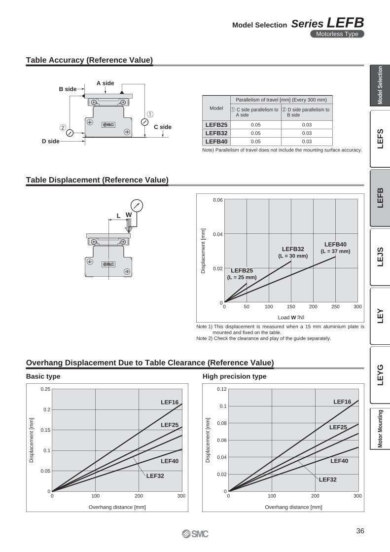
A side
C side
B side
D side
WL
Dis
pla
cem
ent [m
m]
Load W [N]
LEFB25(L = 25 mm)
LEFB32(L = 30 mm)
LEFB40(L = 37 mm)
0.06
0.04
0.02
00 10050 150 250200 300
0
0.05
0.1
0.15
0.2
0.25
Dis
pla
cem
ent [m
m]
0 100 200 300
Overhang distance [mm]
LEF16
LEF25
LEF32
LEF40
0 100 200 300
Dis
pla
cem
ent [m
m]
Overhang distance [mm]
0
0.02
0.04
0.06
0.08
0.1
0.12
LEF16
LEF25
LEF32
LEF40
Table Accuracy (Reference Value)
Table Displacement (Reference Value)
Note) Parallelism of travel does not include the mounting surface accuracy.
Note 1) This displacement is measured when a 15 mm aluminium plate is
mounted and fi xed on the table.
Note 2) Check the clearance and play of the guide separately.
Model
Parallelism of travel [mm] (Every 300 mm)
q C side parallelism to A side
w D side parallelism to B side
LEFB25 0.05 0.03
LEFB32 0.05 0.03
LEFB40 0.05 0.03
Overhang Displacement Due to Table Clearance (Reference Value)
Basic type High precision type
36
Model Selection Series LEFBMotorless Type
LE
FS
LE
FB
LE
JS
LE
YL
EY
GM
od
el
Se
lec
tio
nM
oto
r M
ou
nti
ng
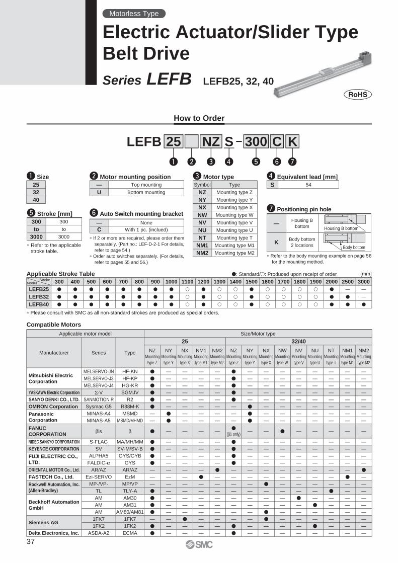
Compatible Motors
�: Standard/�: Produced upon receipt of order
∗ Please consult with SMC as all non-standard strokes are produced as special orders.
Applicable Stroke Table
How to Order
LEFB
q Size r Equivalent lead [mm]
t Stroke [mm]
w Motor mounting position
25 300S
q w e r t
NZ
∗ Refer to the applicable
stroke table.
e Motor type
300 300
to to
3000 3000
— Top mounting
U Bottom mounting
S 5425
32
40
300 400 500 600 700 800 900 1000 1100 1200 1300 1400 1500 1600 1700 1800 1900 2000 2500 3000
LEFB25 � � � � � � � � � � � � � � � � � � — —
LEFB32 � � � � � � � � � � � � � � � � � � � —
LEFB40 � � � � � � � � � � � � � � � � � � � �
Motorless Type
Electric Actuator/Slider TypeBelt Drive
Series LEFB LEFB25, 32, 40
Stroke
[mm]
Model
Applicable motor model Size/Motor type
Manufacturer Series Type
25 32/40
NZ
Mounting
type Z
NY
Mounting
type Y
NX
Mounting
type X
NM1
Mounting
type M1
NM2
Mounting
type M2
NZ
Mounting
type Z
NY
Mounting
type Y
NX
Mounting
type X
NW
Mounting
type W
NV
Mounting
type V
NU
Mounting
type U
NT
Mounting
type T
NM1
Mounting
type M1
NM2
Mounting
type M2
Mitsubishi Electric
Corporation
MELSERVO-JN HF-KN � — — — — � — — — — — — — —
MELSERVO-J3 HF-KP � — — — — � — — — — — — — —
MELSERVO-J4 HG-KR � — — — — � — — — — — — — —
YASKAWA Electric Corporation Σ-V SGMJV � — — — — � — — — — — — — —
SANYO DENKI CO., LTD. SANMOTION R R2 � — — — — � — — — — — — — —
OMRON Corporation Sysmac G5 R88M-K � — — — — — � — — — — — — —
Panasonic
Corporation
MINAS-A4 MSMD — � — — — — � — — — — — — —
MINAS-A5 MSMD/MHMD — � — — — — � — — — — — — —
FANUC
CORPORATIONβis β � — — — —
�(β1 only)
— — � — — — — —
NIDEC SANKYO CORPORATION S-FLAG MA/MH/MM � — — — — � — — — — — — — —
KEYENCE CORPORATION SV SV-M/SV-B � — — — — � — — — — — — — —
FUJI ELECTRIC CO.,
LTD.
ALPHA5 GYS/GYB � — — — — � — — — — — — — —
FALDIC-α GYS � — — — — � — — — — — — — —
ORIENTAL MOTOR Co., Ltd. AR/AZ AR/AZ — — — — � — — — — — — — — �
FASTECH Co., Ltd. Ezi-SERVO EzM — — — � — — — — — — — — � —
Rockwell Automation, Inc.
(Allen-Bradley)
MP-/VP- MP/VP — — — — — — — � — — — — — —
TL TLY-A � — — — — — — — — — — � — —
Beckhoff Automation
GmbH
AM AM30 � — — — — — — — — � — — — —
AM AM31 � — — — — — — — — — � — — —
AM AM80/AM81 � — — — — — — � — — — — — —
Siemens AG1FK7 1FK7 — — � — — — — � — — — — — —
1FK2 1FK2 � — — — — � — — — — � — — —
Delta Electronics, Inc. ASDA-A2 ECMA � — — — — � — — — — — — — —
Symbol Type
NZ Mounting type Z
NY Mounting type Y
NX Mounting type X
NW Mounting type W
NV Mounting type V
NU Mounting type U
NT Mounting type T
NM1 Mounting type M1
NM2 Mounting type M2
∗ If 2 or more are required, please order them
separately. (Part no.: LEF-D-2-1 For details,
refer to page 54.)
∗ Order auto switches separately. (For details,
refer to pages 55 and 56.)
y Auto Switch mounting bracket
— None
C With 1 pc. (inclued)
y u
C K
∗ Refer to the body mounting example on page 58
for the mounting method.
u Positioning pin hole
—Housing B
bottom Housing B bottom
KBody bottom
2 locations Body bottom
37
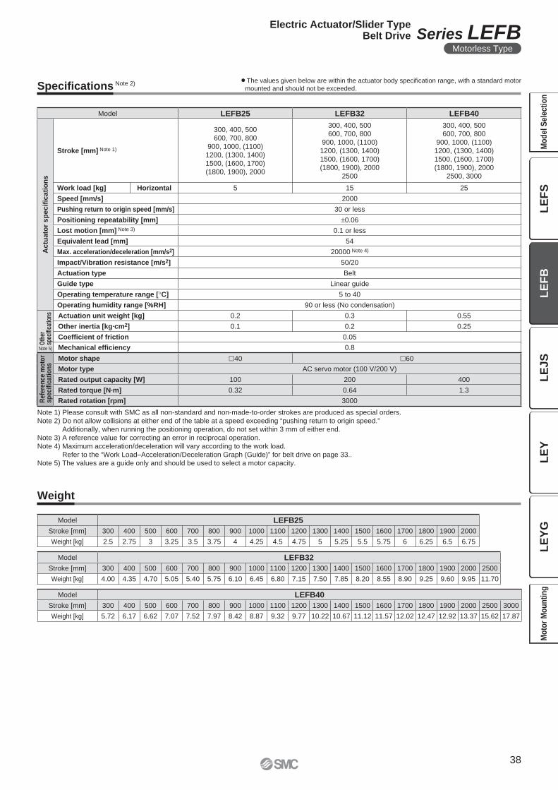
Note 1) Please consult with SMC as all non-standard and non-made-to-order strokes are produced as special orders.
Note 2) Do not allow collisions at either end of the table at a speed exceeding “pushing return to origin speed.”
Additionally, when running the positioning operation, do not set within 3 mm of either end.
Note 3) A reference value for correcting an error in reciprocal operation.
Note 4) Maximum acceleration/deceleration will vary according to the work load.
Refer to the “Work Load–Acceleration/Deceleration Graph (Guide)” for belt drive on page 33..
Note 5) The values are a guide only and should be used to select a motor capacity.
Specifi cations Note 2) ¡The values given below are within the actuator body specifi cation range, with a standard motor
mounted and should not be exceeded.
Model LEFB25 LEFB32 LEFB40
Actu
ato
r sp
ecifi
cati
on
s
Stroke [mm] Note 1)
300, 400, 500
600, 700, 800
900, 1000, (1100)
1200, (1300, 1400)
1500, (1600, 1700)
(1800, 1900), 2000
300, 400, 500
600, 700, 800
900, 1000, (1100)
1200, (1300, 1400)
1500, (1600, 1700)
(1800, 1900), 2000
2500
300, 400, 500
600, 700, 800
900, 1000, (1100)
1200, (1300, 1400)
1500, (1600, 1700)
(1800, 1900), 2000
2500, 3000
Work load [kg] Horizontal 5 15 25
Speed [mm/s] 2000
Pushing return to origin speed [mm/s] 30 or less
Positioning repeatability [mm] ±0.06
Lost motion [mm] Note 3) 0.1 or less
Equivalent lead [mm] 54
Max. acceleration/deceleration [mm/s2] 20000 Note 4)
Impact/Vibration resistance [m/s2] 50/20
Actuation type Belt
Guide type Linear guide
Operating temperature range [°C] 5 to 40
Operating humidity range [%RH] 90 or less (No condensation)
Oth
er
spec
ifi ca
tions Actuation unit weight [kg] 0.2 0.3 0.55
Other inertia [kg·cm2] 0.1 0.2 0.25
Coeffi cient of friction 0.05
Mechanical effi ciency 0.8
Refe
ren
ce m
oto
rsp
ecifi
cati
on
s
Motor shape �40 �60
Motor type AC servo motor (100 V/200 V)
Rated output capacity [W] 100 200 400
Rated torque [N·m] 0.32 0.64 1.3
Rated rotation [rpm] 3000
Note 5)
Weight
Model LEFB40
Stroke [mm] 300 400 500 600 700 800 900 1000 1100 1200 1300 1400 1500 1600 1700 1800 1900 2000 2500 3000
Weight [kg] 5.72 6.17 6.62 7.07 7.52 7.97 8.42 8.87 9.32 9.77 10.22 10.67 11.12 11.57 12.02 12.47 12.92 13.37 15.62 17.87
Model LEFB32
Stroke [mm] 300 400 500 600 700 800 900 1000 1100 1200 1300 1400 1500 1600 1700 1800 1900 2000 2500
Weight [kg] 4.00 4.35 4.70 5.05 5.40 5.75 6.10 6.45 6.80 7.15 7.50 7.85 8.20 8.55 8.90 9.25 9.60 9.95 11.70
Model LEFB25
Stroke [mm] 300 400 500 600 700 800 900 1000 1100 1200 1300 1400 1500 1600 1700 1800 1900 2000
Weight [kg] 2.5 2.75 3 3.25 3.5 3.75 4 4.25 4.5 4.75 5 5.25 5.5 5.75 6 6.25 6.5 6.75
38
Electric Actuator/Slider TypeBelt Drive Series LEFB
Motorless Type
LE
FS
LE
FB
LE
JS
LE
YL
EY
GM
od
el
Se
lec
tio
nM
oto
r M
ou
nti
ng
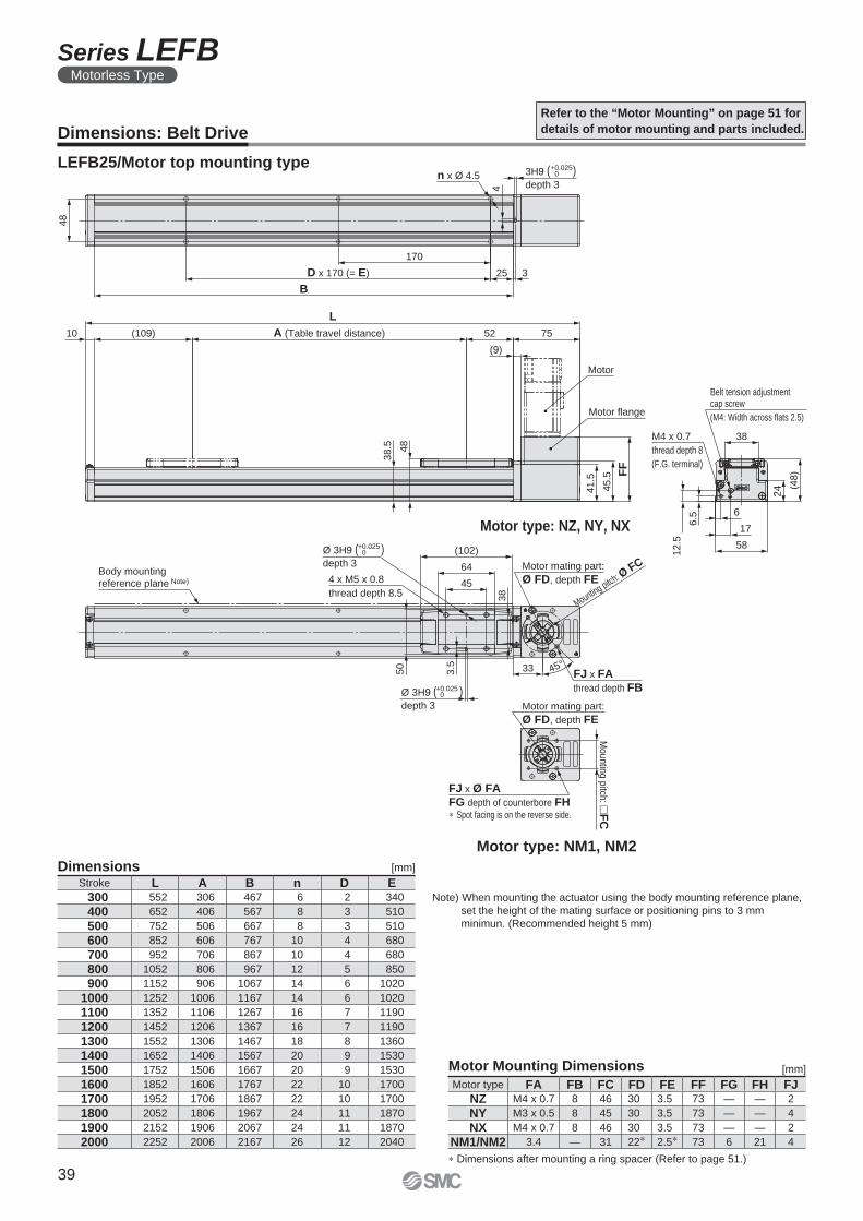
4 x M5 x 0.8
thread depth 8.5
(102)
64
45
Body mounting
reference plane Note)
33
38
45°FJ x FA
thread depth FB
3.5
50
Mounting pitch: Ø FCMotor mating part:
Ø FD, depth FE
Ø 3H9 ( )depth 3
+0.0250
Ø 3H9 ( )depth 3
+0.0250
M4 x 0.7
thread depth 8
(F.G. terminal)
Belt tension adjustmentcap screw
(M4: Width across flats 2.5)
38
(48)
24
58
17
6
6.5
12.5
3H9 ( )depth 3
L
(109)10 A (Table travel distance) 52 75
(9)
FF
45.5
41.5
48
38.5
Motor
48
B
D x 170 (= E)
170
25 3
n x Ø 4.5
4
Motor flange
FJ x Ø FA
FG depth of counterbore FH∗ Spot facing is on the reverse side.
Motor mating part:
Ø FD, depth FE
Mountin
g p
itch: �
FC
+0.0250
Dimensions: Belt Drive
Refer to the “Motor Mounting” on page 51 for
details of motor mounting and parts included.
Note) When mounting the actuator using the body mounting reference plane,
set the height of the mating surface or positioning pins to 3 mm
minimun. (Recommended height 5 mm)
Motor type: NM1, NM2
Motor type: NZ, NY, NX
LEFB25/Motor top mounting type
Dimensions [mm]
Stroke L A B n D E 300 552 306 467 6 2 340
400 652 406 567 8 3 510
500 752 506 667 8 3 510
600 852 606 767 10 4 680
700 952 706 867 10 4 680
800 1052 806 967 12 5 850
900 1152 906 1067 14 6 1020
1000 1252 1006 1167 14 6 1020
1100 1352 1106 1267 16 7 1190
1200 1452 1206 1367 16 7 1190
1300 1552 1306 1467 18 8 1360
1400 1652 1406 1567 20 9 1530
1500 1752 1506 1667 20 9 1530
1600 1852 1606 1767 22 10 1700
1700 1952 1706 1867 22 10 1700
1800 2052 1806 1967 24 11 1870
1900 2152 1906 2067 24 11 1870
2000 2252 2006 2167 26 12 2040
Motor Mounting Dimensions
∗ Dimensions after mounting a ring spacer (Refer to page 51.)
Motor type FA FB FC FD FE FF FG FH FJNZ M4 x 0.7 8 46 30 3.5 73 — — 2
NY M3 x 0.5 8 45 30 3.5 73 — — 4
NX M4 x 0.7 8 46 30 3.5 73 — — 2
NM1/NM2 3.4 — 31 22∗ 2.5∗ 73 6 21 4
[mm]
39
Series LEFBMotorless Type
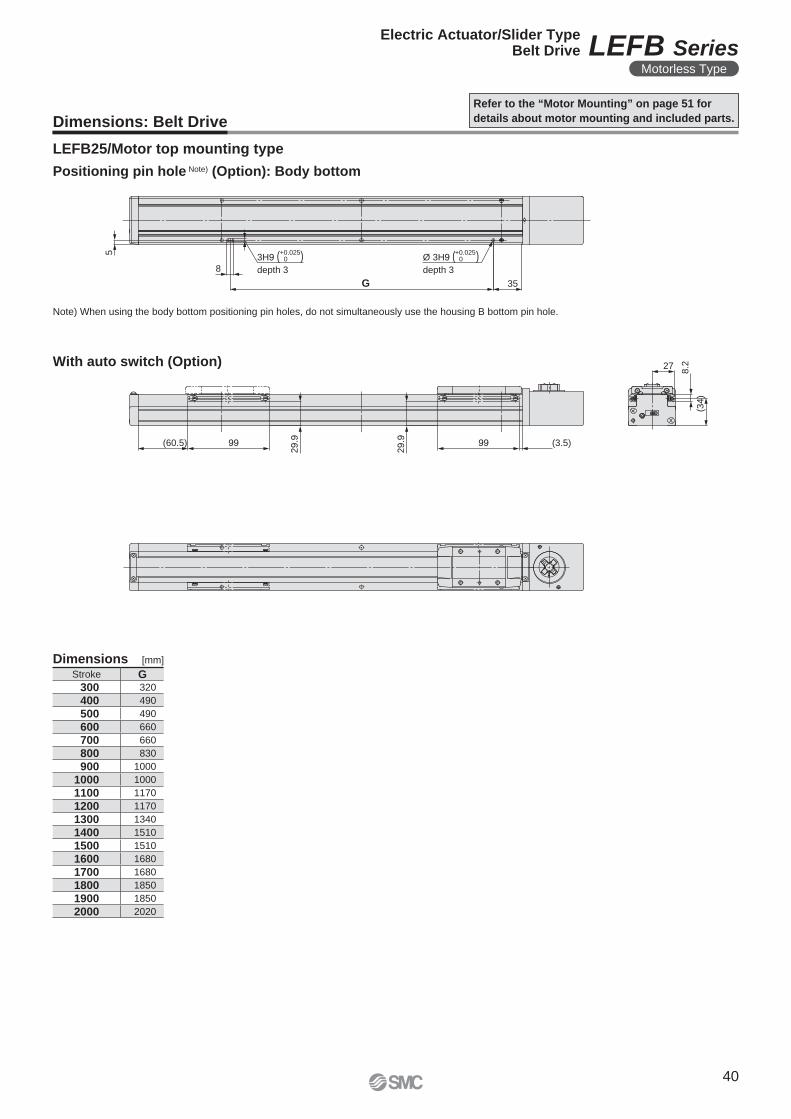
5
8
G 35
3H9 ( )depth 3
Ø 3H9 ( )depth 3
27
8.2
(34
)
(60.5) 99
29.9 (3.5)99
29.9
+0.0250
+0.0250
Dimensions: Belt Drive
Refer to the “Motor Mounting” on page 51 for
details about motor mounting and included parts.
LEFB25/Motor top mounting type
Note) When using the body bottom positioning pin holes, do not simultaneously use the housing B bottom pin hole.
Positioning pin hole Note) (Option): Body bottom
Dimensions [mm]
Stroke G 300 320
400 490
500 490
600 660
700 660
800 830
900 1000
1000 1000
1100 1170
1200 1170
1300 1340
1400 1510
1500 1510
1600 1680
1700 1680
1800 1850
1900 1850
2000 2020
With auto switch (Option)
40
Electric Actuator/Slider TypeBelt Drive LEFB Series
Motorless Type
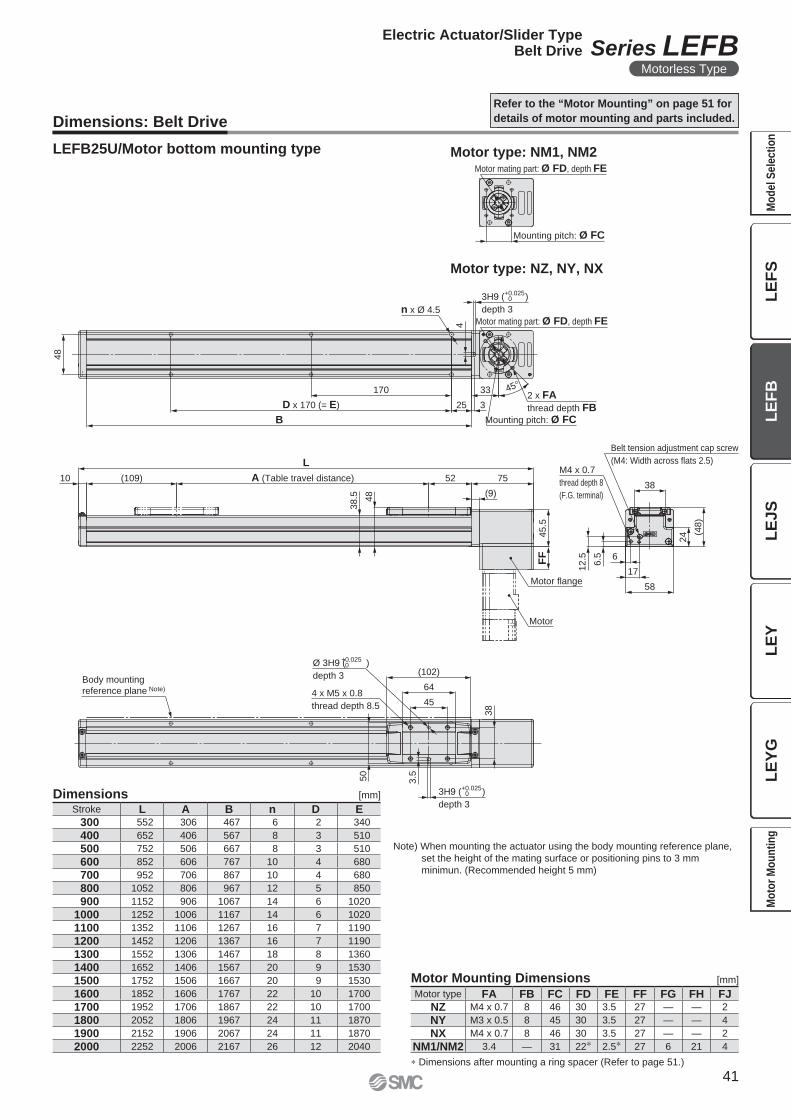
Body mounting
reference plane Note)
Ø 3H9 ( )
depth 3
3H9 ( )
depth 3
3H9 ( )
depth 3
4 x M5 x 0.8
thread depth 8.5
(102)
64
45
38
3.550
Belt tension adjustment cap screw
(M4: Width across flats 2.5)
38
M4 x 0.7
thread depth 8
(F.G. terminal)
(48
)
24
58
1712
.5
6.5 6
L
A (Table travel distance) 52 75(109)10
38
.5 48 (9)
45
.5F
F
Motor flange
n x Ø 4.5
48
4
45°2 x FA
thread depth FBB
D x 170 (= E)
170
25
33
3
Motor
Mounting pitch: Ø FC
Motor mating part: Ø FD, depth FE
Mounting pitch: Ø FC
Motor mating part: Ø FD, depth FE
+0.0250
+0.0250
+0.0250
LEFB25U/Motor bottom mounting type
Dimensions: Belt Drive
Dimensions [mm]
Motor Mounting Dimensions [mm]
∗ Dimensions after mounting a ring spacer (Refer to page 51.)
Note) When mounting the actuator using the body mounting reference plane,
set the height of the mating surface or positioning pins to 3 mm
minimun. (Recommended height 5 mm)
Motor type: NM1, NM2
Motor type: NZ, NY, NX
Refer to the “Motor Mounting” on page 51 for
details of motor mounting and parts included.
Motor type FA FB FC FD FE FF FG FH FJNZ M4 x 0.7 8 46 30 3.5 27 — — 2
NY M3 x 0.5 8 45 30 3.5 27 — — 4
NX M4 x 0.7 8 46 30 3.5 27 — — 2
NM1/NM2 3.4 — 31 22∗ 2.5∗ 27 6 21 4
Stroke L A B n D E 300 552 306 467 6 2 340
400 652 406 567 8 3 510
500 752 506 667 8 3 510
600 852 606 767 10 4 680
700 952 706 867 10 4 680
800 1052 806 967 12 5 850
900 1152 906 1067 14 6 1020
1000 1252 1006 1167 14 6 1020
1100 1352 1106 1267 16 7 1190
1200 1452 1206 1367 16 7 1190
1300 1552 1306 1467 18 8 1360
1400 1652 1406 1567 20 9 1530
1500 1752 1506 1667 20 9 1530
1600 1852 1606 1767 22 10 1700
1700 1952 1706 1867 22 10 1700
1800 2052 1806 1967 24 11 1870
1900 2152 1906 2067 24 11 1870
2000 2252 2006 2167 26 12 2040
41
Electric Actuator/Slider TypeBelt Drive Series LEFB
Motorless Type
LE
FS
LE
FB
LE
JS
LE
YL
EY
GM
od
el
Se
lec
tio
nM
oto
r M
ou
nti
ng
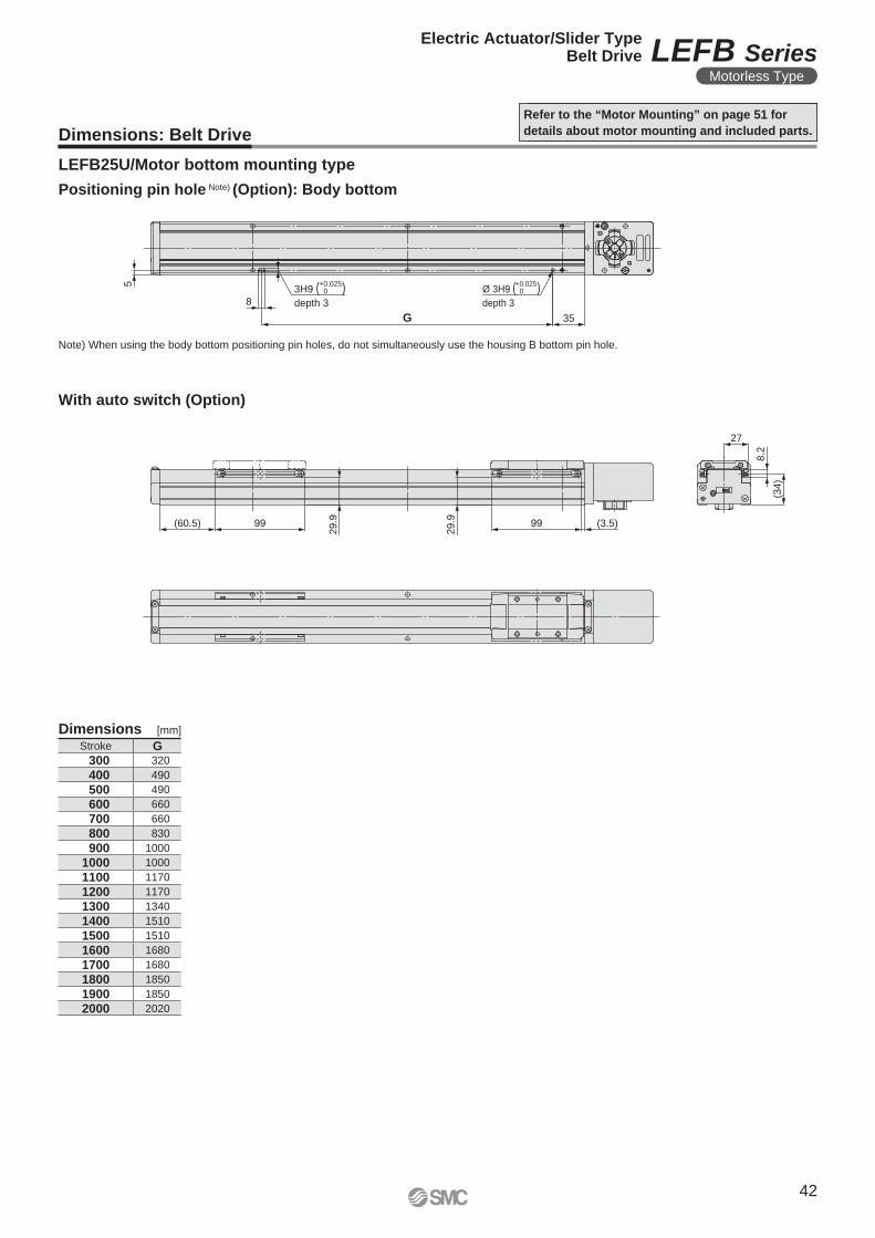
5
8
G 35
3H9 ( )depth 3
Ø 3H9 ( )depth 3
27
8.2
(34)
(60.5) 99
29.9 (3.5)99
29.9
+0.0250
+0.0250
LEFB25U/Motor bottom mounting type
Dimensions: Belt Drive
Refer to the “Motor Mounting” on page 51 for
details about motor mounting and included parts.
Note) When using the body bottom positioning pin holes, do not simultaneously use the housing B bottom pin hole.
Positioning pin hole Note) (Option): Body bottom
Dimensions [mm]
Stroke G 300 320
400 490
500 490
600 660
700 660
800 830
900 1000
1000 1000
1100 1170
1200 1170
1300 1340
1400 1510
1500 1510
1600 1680
1700 1680
1800 1850
1900 1850
2000 2020
With auto switch (Option)
42
Electric Actuator/Slider TypeBelt Drive LEFB Series
Motorless Type
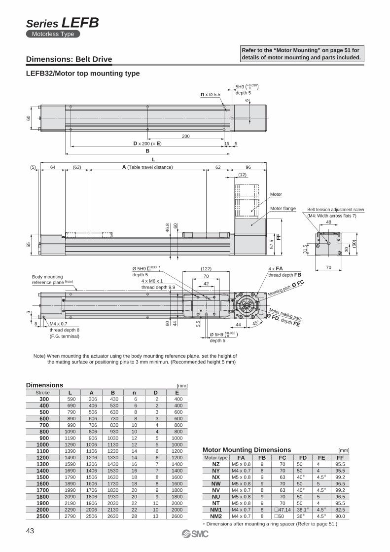
M4 x 0.7
thread depth 8
(F.G. terminal)
8
6
Body mounting
reference plane Note) 4 x M6 x 1
thread depth 9.9
(122)
70
42
44 45°
4 x FA
thread depth FB
Mounting pitch: Ø FC
Motor mating part:Ø FD, depth FE5
.544
60
L
A (Table travel distance)(62)64(5)
55
62 96
(12)
Motor
FF
57
.5
48
31.5
30
70
(60
)
60
5H9 ( )depth 5n x Ø 5.5
200
D x 200 (= E)
B
515
6
46
.8 60
Motor flange Belt tension adjustment screw
(M4: Width across flats 7)
Ø 5H9 ( )depth 5
+0.0300
Ø 5H9 ( )depth 5
+0.0300
+0.0300
Dimensions: Belt Drive
Refer to the “Motor Mounting” on page 51 for
details of motor mounting and parts included.
LEFB32/Motor top mounting type
Dimensions [mm]
Note) When mounting the actuator using the body mounting reference plane, set the height of
the mating surface or positioning pins to 3 mm minimun. (Recommended height 5 mm)
[mm]
Stroke L A B n D E 300 590 306 430 6 2 400
400 690 406 530 6 2 400
500 790 506 630 8 3 600
600 890 606 730 8 3 600
700 990 706 830 10 4 800
800 1090 806 930 10 4 800
900 1190 906 1030 12 5 1000
1000 1290 1006 1130 12 5 1000
1100 1390 1106 1230 14 6 1200
1200 1490 1206 1330 14 6 1200
1300 1590 1306 1430 16 7 1400
1400 1690 1406 1530 16 7 1400
1500 1790 1506 1630 18 8 1600
1600 1890 1606 1730 18 8 1600
1700 1990 1706 1830 20 9 1800
1800 2090 1806 1930 20 9 1800
1900 2190 1906 2030 22 10 2000
2000 2290 2006 2130 22 10 2000
2500 2790 2506 2630 28 13 2600
Motor Mounting Dimensions
∗ Dimensions after mounting a ring spacer (Refer to page 51.)
Motor type FA FB FC FD FE FFNZ M5 x 0.8 9 70 50 4 95.5
NY M4 x 0.7 8 70 50 4 95.5
NX M5 x 0.8 9 63 40∗ 4.5∗ 99.2
NW M5 x 0.8 9 70 50 5 96.5
NV M4 x 0.7 8 63 40∗ 4.5∗ 99.2
NU M5 x 0.8 9 70 50 5 96.5
NT M5 x 0.8 9 70 50 4 95.5
NM1 M4 x 0.7 8 �47.14 38.1∗ 4.5∗ 82.5
NM2 M4 x 0.7 8 �50 36∗ 4.5∗ 90.0
43
Series LEFBMotorless Type
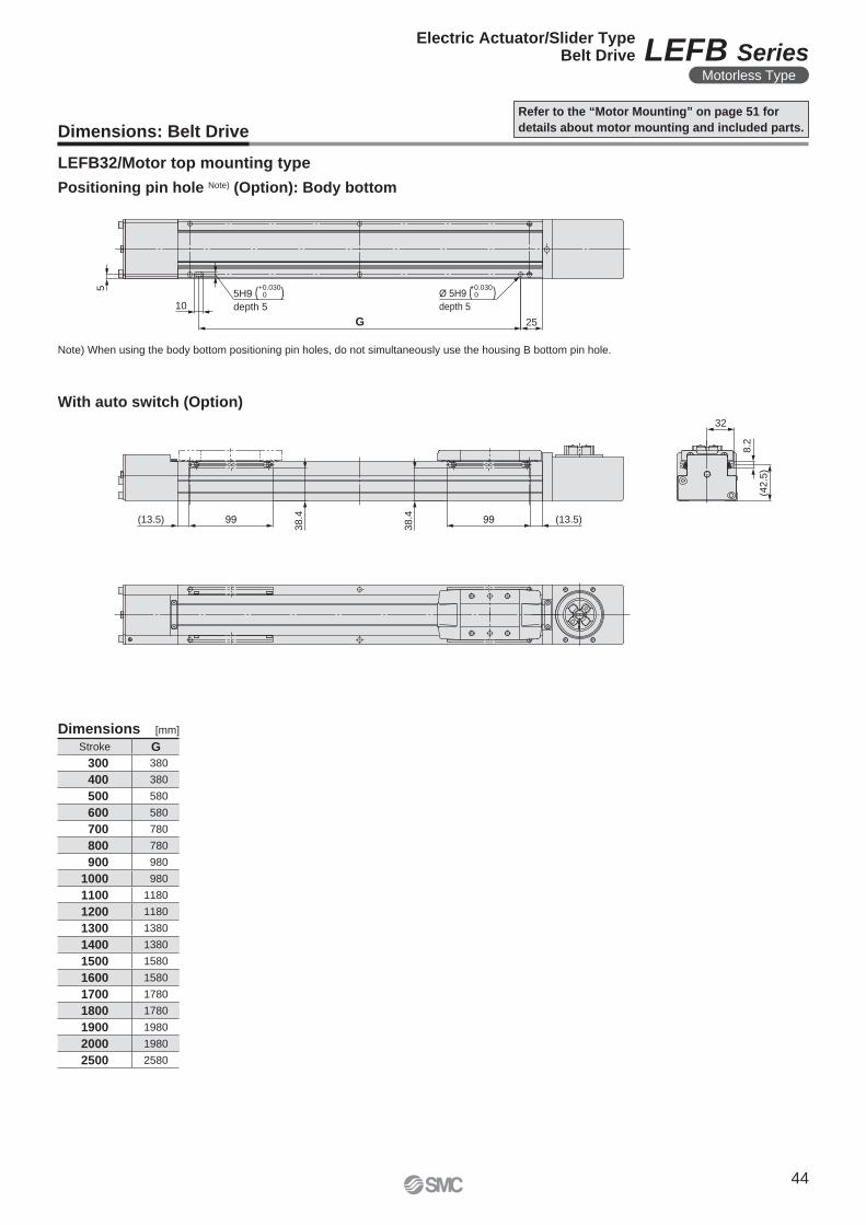
32
8.2
(42.5
)
(13.5)99
38.4
38.499(13.5)
5
10
G 25
Ø 5H9 ( )depth 5
5H9 ( )depth 5
+0.0300
+0.0300
Dimensions: Belt Drive
Refer to the “Motor Mounting” on page 51 for
details about motor mounting and included parts.
LEFB32/Motor top mounting type
Note) When using the body bottom positioning pin holes, do not simultaneously use the housing B bottom pin hole.
Positioning pin hole Note) (Option): Body bottom
Dimensions [mm]
Stroke G
300 380
400 380
500 580
600 580
700 780
800 780
900 980
1000 980
1100 1180
1200 1180
1300 1380
1400 1380
1500 1580
1600 1580
1700 1780
1800 1780
1900 1980
2000 1980
2500 2580
With auto switch (Option)
44
Electric Actuator/Slider TypeBelt Drive LEFB Series
Motorless Type
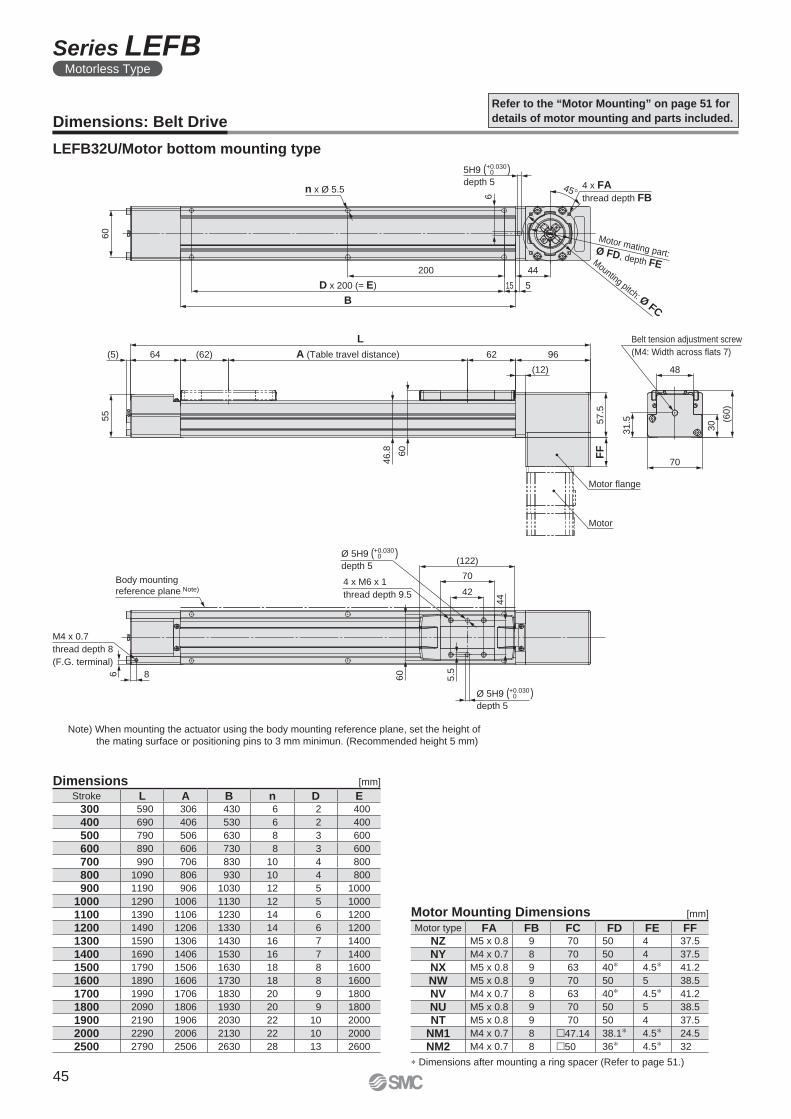
M4 x 0.7
thread depth 8
(F.G. terminal)
Body mounting
reference plane Note)
(122)
70
424 x M6 x 1
thread depth 9.5
60
44
31.5
48
30 (6
0)
70
Belt tension adjustment screw
(M4: Width across flats 7)
55
L
A (Table travel distance)(62)64(5) 62 96
(12)
57.5
FF
Motor
46.8 60
60
n x Ø 5.5
D x 200 (= E)
B
200 44
6
15 5
4 x FA
thread depth FB45°
5.5
Motor mating part: Ø FD, depth FEMounting pitch: Ø FC
Motor flange
Ø 5H9 ( )depth 5
+0.0300
Ø 5H9 ( )depth 5
+0.0300
5H9 ( )depth 5
+0.0300
86
LEFB32U/Motor bottom mounting type
Dimensions: Belt Drive
Refer to the “Motor Mounting” on page 51 for
details of motor mounting and parts included.
Dimensions [mm]
Note) When mounting the actuator using the body mounting reference plane, set the height of
the mating surface or positioning pins to 3 mm minimun. (Recommended height 5 mm)
Stroke L A B n D E 300 590 306 430 6 2 400
400 690 406 530 6 2 400
500 790 506 630 8 3 600
600 890 606 730 8 3 600
700 990 706 830 10 4 800
800 1090 806 930 10 4 800
900 1190 906 1030 12 5 1000
1000 1290 1006 1130 12 5 1000
1100 1390 1106 1230 14 6 1200
1200 1490 1206 1330 14 6 1200
1300 1590 1306 1430 16 7 1400
1400 1690 1406 1530 16 7 1400
1500 1790 1506 1630 18 8 1600
1600 1890 1606 1730 18 8 1600
1700 1990 1706 1830 20 9 1800
1800 2090 1806 1930 20 9 1800
1900 2190 1906 2030 22 10 2000
2000 2290 2006 2130 22 10 2000
2500 2790 2506 2630 28 13 2600
Motor Mounting Dimensions [mm]
∗ Dimensions after mounting a ring spacer (Refer to page 51.)
Motor type FA FB FC FD FE FFNZ M5 x 0.8 9 70 50 4 37.5
NY M4 x 0.7 8 70 50 4 37.5
NX M5 x 0.8 9 63 40∗ 4.5∗ 41.2
NW M5 x 0.8 9 70 50 5 38.5
NV M4 x 0.7 8 63 40∗ 4.5∗ 41.2
NU M5 x 0.8 9 70 50 5 38.5
NT M5 x 0.8 9 70 50 4 37.5
NM1 M4 x 0.7 8 �47.14 38.1∗ 4.5∗ 24.5
NM2 M4 x 0.7 8 �50 36∗ 4.5∗ 32
45
Series LEFBMotorless Type
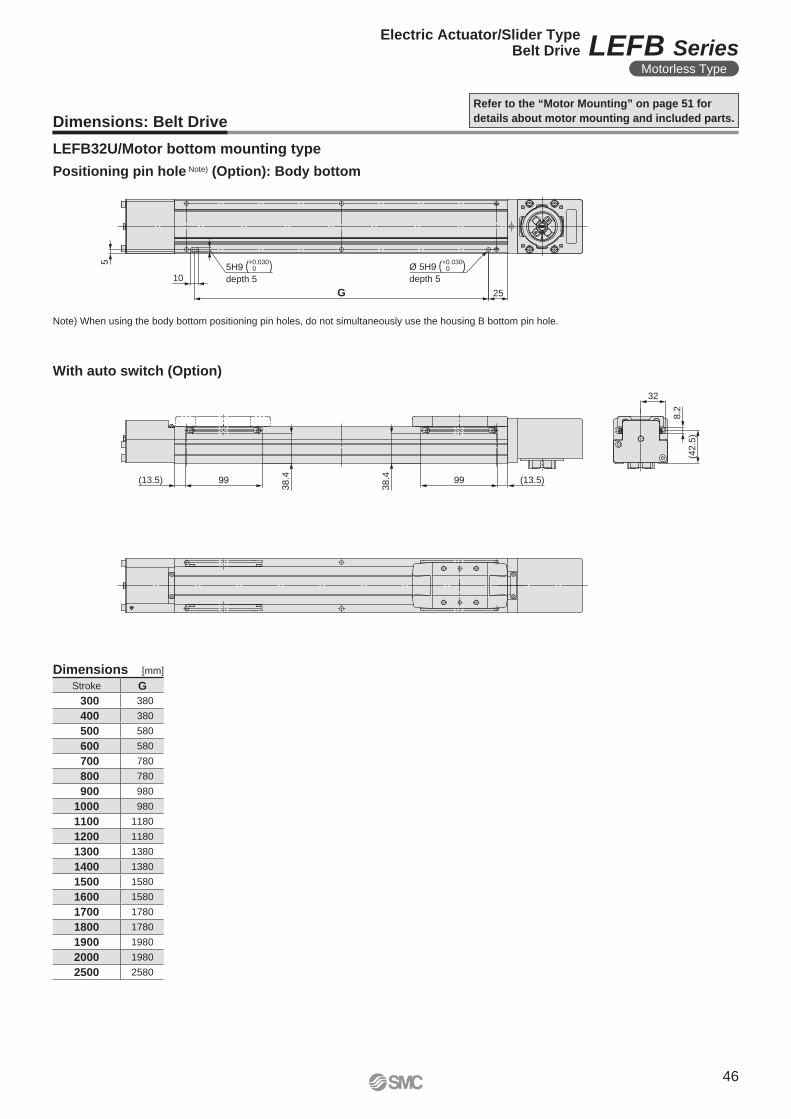
32
8.2
(42.5
)
(13.5)99
38.4
38.499(13.5)
5
10
G 25
Ø 5H9 ( )depth 5
5H9 ( )depth 5
+0.0300
+0.0300
LEFB32U/Motor bottom mounting type
Dimensions: Belt Drive
Refer to the “Motor Mounting” on page 51 for
details about motor mounting and included parts.
Note) When using the body bottom positioning pin holes, do not simultaneously use the housing B bottom pin hole.
Positioning pin hole Note) (Option): Body bottom
Dimensions [mm]
Stroke G
300 380
400 380
500 580
600 580
700 780
800 780
900 980
1000 980
1100 1180
1200 1180
1300 1380
1400 1380
1500 1580
1600 1580
1700 1780
1800 1780
1900 1980
2000 1980
2500 2580
With auto switch (Option)
46
Electric Actuator/Slider TypeBelt Drive LEFB Series
Motorless Type
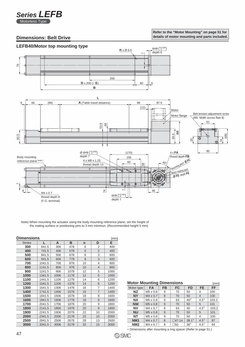
4 x FA
thread depth FB
46
45°
Motor mating part:
Ø FD, depth FE
Mounting pitch: Ø FC
(170)
106
60
Ø 6H9 ( )depth 7
4 x M8 x 1.25
thread depth 13
Body mounting
reference plane Note )
M4 x 0.7
thread depth 8
(F.G. terminal)
7
8
58
7
74
L
A (Table travel distance)(86)666 86 97.5
(12)
60
.5
65
.5
FF
61
33
31
(68
)
90
Belt tension adjustment screw
(M5: Width across flats 8)
Motor
Motor flange
53
.8 68
76
n x Ø 6.6
7
6H9 ( )depth 6
200
D x 200 (= E)
B
60 5
+0.0300
6H9 ( )depth 7
+0.0300
+0.0300
LEFB40/Motor top mounting type
Dimensions: Belt Drive
Refer to the “Motor Mounting” on page 51 for
details of motor mounting and parts included.
Dimensions [mm]
Note) When mounting the actuator using the body mounting reference plane, set the height of
the mating surface or positioning pins to 3 mm minimun. (Recommended height 5 mm)
Stroke L A B n D E 300 641.5 306 478 6 2 400
400 741.5 406 578 6 2 400
500 841.5 506 678 8 3 600
600 941.5 606 778 8 3 600
700 1041.5 706 878 10 4 800
800 1141.5 806 978 10 4 800
900 1241.5 906 1078 12 5 1000
1000 1341.5 1006 1178 12 5 1000
1100 1441.5 1106 1278 14 6 1200
1200 1541.5 1206 1378 14 6 1200
1300 1641.5 1306 1478 16 7 1400
1400 1741.5 1406 1578 16 7 1400
1500 1841.5 1506 1678 18 8 1600
1600 1941.5 1606 1778 18 8 1600
1700 2041.5 1706 1878 20 9 1800
1800 2141.5 1806 1978 20 9 1800
1900 2241.5 1906 2078 22 10 2000
2000 2341.5 2006 2178 22 10 2000
2500 2841.5 2506 2678 28 13 2600
3000 3341.5 3006 3178 32 15 3000
Motor Mounting Dimensions [mm]
∗ Dimensions after mounting a ring spacer (Refer to page 51.)
Motor type FA FB FC FD FE FFNZ M5 x 0.8 9 70 50 4 100
NY M4 x 0.7 8 70 50 4 100
NX M5 x 0.8 9 63 40∗ 4.5∗ 103.2
NW M5 x 0.8 9 70 50 5 101
NV M4 x 0.7 8 63 40 4.5∗ 103.2
NU M5 x 0.8 9 70 50 5 101
NT M5 x 0.8 9 70 50 4 100
NM1 M4 x 0.7 8 �47.14 38.1∗ 4.5∗ 87
NM2 M4 x 0.7 8 �50 36∗ 4.5∗ 94
47
Series LEFBMotorless Type
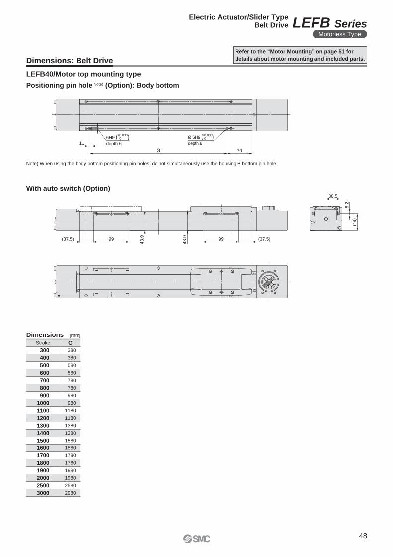
11
G 70
Ø 6H9 ( )depth 6
6H9 ( )depth 6
(48)
8.2
38.5
99
43.9(37.5)
43.9 99 (37.5)
+0.0300
+0.0300
LEFB40/Motor top mounting type
Dimensions: Belt Drive
Refer to the “Motor Mounting” on page 51 for
details about motor mounting and included parts.
Note) When using the body bottom positioning pin holes, do not simultaneously use the housing B bottom pin hole.
Positioning pin hole Note) (Option): Body bottom
Dimensions [mm]
Stroke G
300 380
400 380
500 580
600 580
700 780
800 780
900 980
1000 980
1100 1180
1200 1180
1300 1380
1400 1380
1500 1580
1600 1580
1700 1780
1800 1780
1900 1980
2000 1980
2500 2580
3000 2980
With auto switch (Option)
48
Electric Actuator/Slider TypeBelt Drive LEFB Series
Motorless Type
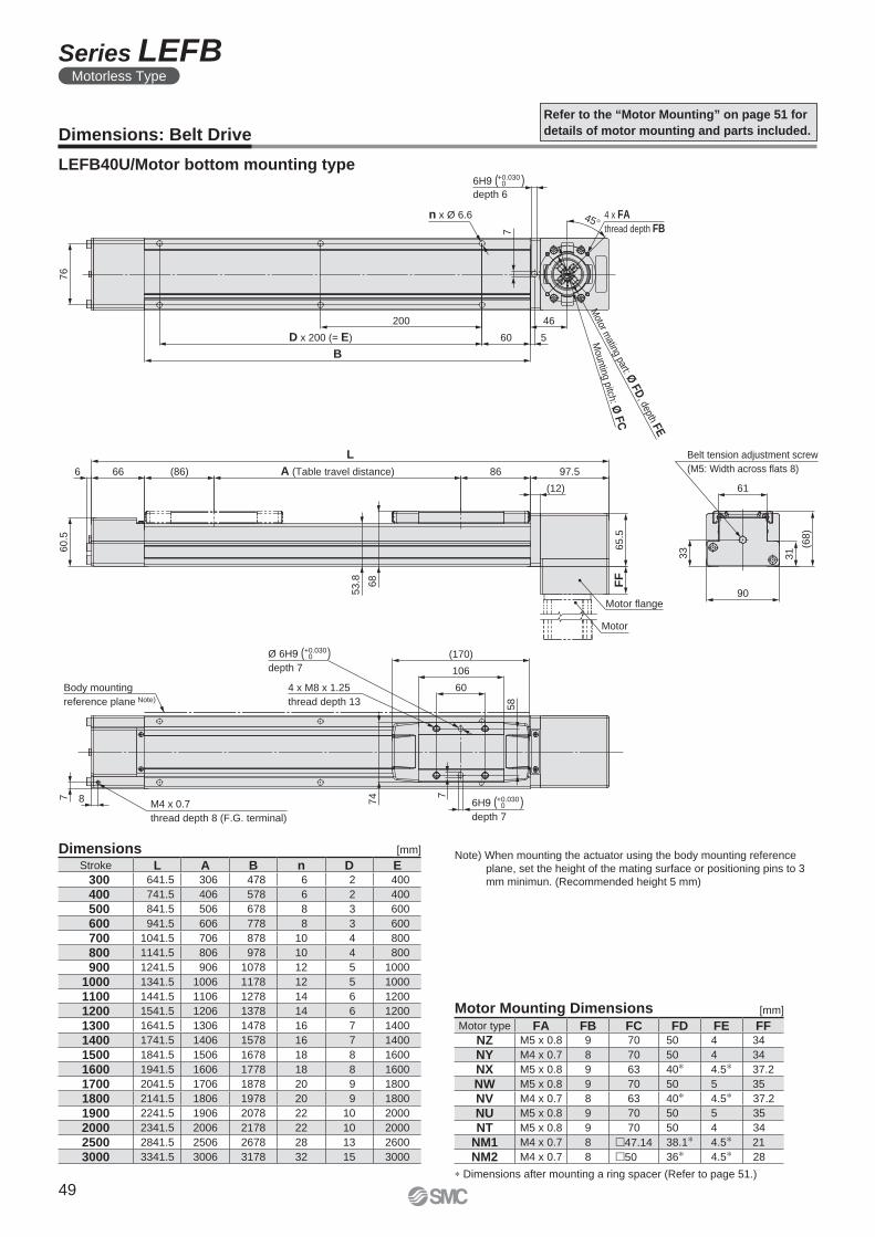
33
90
31
61
(68
)
Belt tension adjustment screw
(M5: Width across flats 8)
76
B
D x 200 (= E)
200
60
46
5
6H9 ( )depth 6
6H9 ( )depth 7
Ø 6H9 ( )depth 7
Motor m
ating part: Ø F
D, depth F
E
Mounting pitch: Ø
FC
45°
7
n x Ø 6.6 4 x FA
thread depth FB
Motor
Motor flange
65
.5F
F
60
.5
A (Table travel distance)66 (86)
L
86 97.56
(12)
Body mounting
reference plane Note)
60
106
(170)
4 x M8 x 1.25
thread depth 13
7 8M4 x 0.7
thread depth 8 (F.G. terminal)
7
74
53
.8 68
58
+0.0300
+0.0300
+0.0300
LEFB40U/Motor bottom mounting type
Dimensions: Belt Drive
Refer to the “Motor Mounting” on page 51 for
details of motor mounting and parts included.
Dimensions [mm]Note) When mounting the actuator using the body mounting reference
plane, set the height of the mating surface or positioning pins to 3
mm minimun. (Recommended height 5 mm)
Stroke L A B n D E 300 641.5 306 478 6 2 400
400 741.5 406 578 6 2 400
500 841.5 506 678 8 3 600
600 941.5 606 778 8 3 600
700 1041.5 706 878 10 4 800
800 1141.5 806 978 10 4 800
900 1241.5 906 1078 12 5 1000
1000 1341.5 1006 1178 12 5 1000
1100 1441.5 1106 1278 14 6 1200
1200 1541.5 1206 1378 14 6 1200
1300 1641.5 1306 1478 16 7 1400
1400 1741.5 1406 1578 16 7 1400
1500 1841.5 1506 1678 18 8 1600
1600 1941.5 1606 1778 18 8 1600
1700 2041.5 1706 1878 20 9 1800
1800 2141.5 1806 1978 20 9 1800
1900 2241.5 1906 2078 22 10 2000
2000 2341.5 2006 2178 22 10 2000
2500 2841.5 2506 2678 28 13 2600
3000 3341.5 3006 3178 32 15 3000
Motor Mounting Dimensions [mm]
∗ Dimensions after mounting a ring spacer (Refer to page 51.)
Motor type FA FB FC FD FE FFNZ M5 x 0.8 9 70 50 4 34
NY M4 x 0.7 8 70 50 4 34
NX M5 x 0.8 9 63 40∗ 4.5∗ 37.2
NW M5 x 0.8 9 70 50 5 35
NV M4 x 0.7 8 63 40∗ 4.5∗ 37.2
NU M5 x 0.8 9 70 50 5 35
NT M5 x 0.8 9 70 50 4 34
NM1 M4 x 0.7 8 �47.14 38.1∗ 4.5∗ 21
NM2 M4 x 0.7 8 �50 36∗ 4.5∗ 28
49
Series LEFBMotorless Type
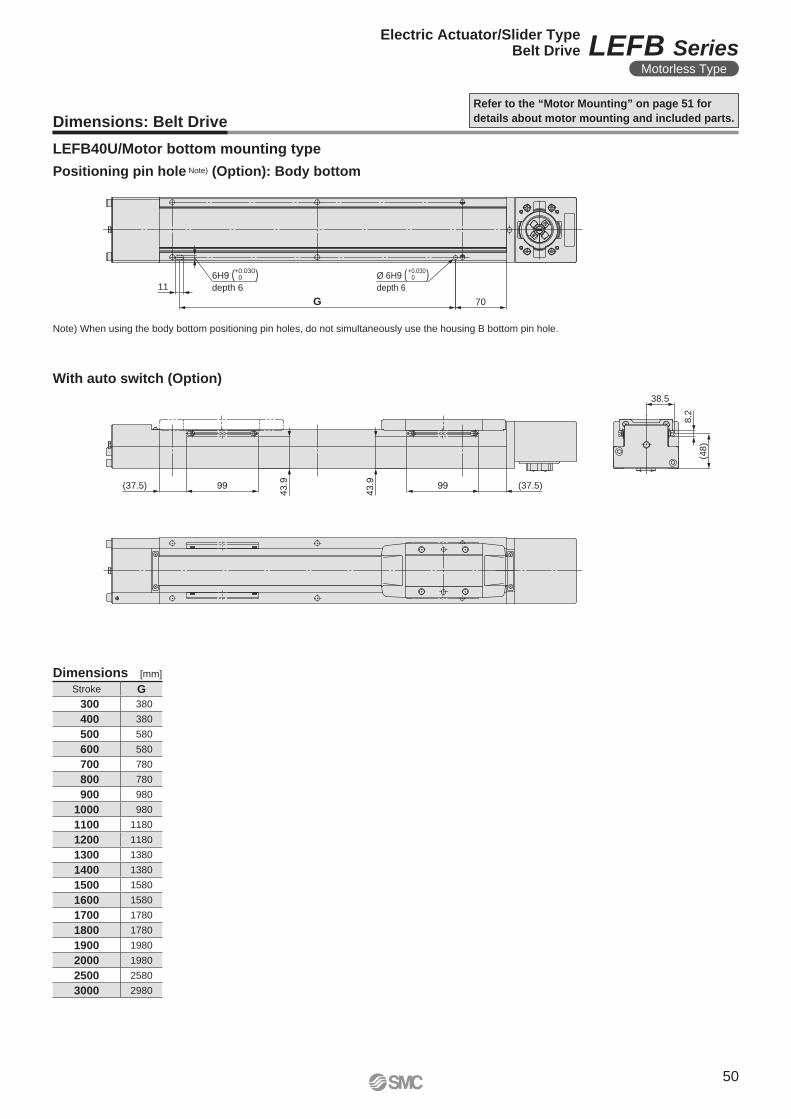
11
G 70
Ø 6H9 ( )depth 6
6H9 ( )depth 6
(48)
8.2
38.5
99
43.9(37.5)
43.9 99 (37.5)
+0.0300
+0.0300
LEFB40U/Motor bottom mounting type
Dimensions: Belt Drive
Refer to the “Motor Mounting” on page 51 for
details about motor mounting and included parts.
Note) When using the body bottom positioning pin holes, do not simultaneously use the housing B bottom pin hole.
Positioning pin hole Note) (Option): Body bottom
Dimensions [mm]
Stroke G
300 380
400 380
500 580
600 580
700 780
800 780
900 980
1000 980
1100 1180
1200 1180
1300 1380
1400 1380
1500 1580
1600 1580
1700 1780
1800 1780
1900 1980
2000 1980
2500 2580
3000 2980
With auto switch (Option)
50
Electric Actuator/Slider TypeBelt Drive LEFB Series
Motorless Type
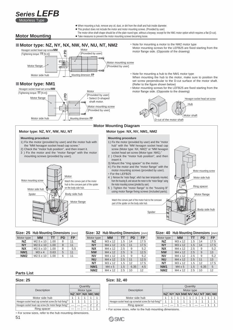
Motor
[Provided by user]
Motor mounting screw
[Provided by user]
Mounting dimension: FP
Hexagon socket head cap screw/MM
(Tightening torque: TT [N·m])
Motor flange
Motor side hub
Ø P
D
Hexagon socket head set screw/MM
(Tightening torque: TT [N·m])
Motor flange
Motor
[Provided by user]
∗ Select D-shaped
shaft motor.
Motor mounting screw
[Provided by user]
Motor side hub Mounting dimension: FP
Ø P
D
Hexagon socket head set screw
Hub
Motor shaft
D-cut of the motor shaft
Motor mounting screw
Motor side hub
Spider
Motor
Motor flange
Body side hub
Match the convex part of the motor
hub to the concave part of the spider
on the body side hub.
Motor mounting screw
Motor side hub
Ring spacer
Motor flange
Body side hubSpider
Match the convex part of the motor hub to the concave
part of the spider on the body side hub.
Size: 25 Size: 32, 40
∗ For screw sizes, refer to the hub mounting dimensions.
∗ For screw sizes, refer to the hub mounting dimensions.
Motor Mounting
Parts List
�Motor type: NM1
�Motor type: NZ, NY, NX, NW, NV, NU, NT, NM2
Motor type: NZ, NY, NW, NU, NT Motor type: NX, NV, NM1, NM2
∗ Note for mounting a hub to the NM1 motor type
When mounting the hub to the motor, make sure to position the
set screw perpendicular to the D-cut surface of the motor shaft.
(Refer to the fi gure shown below)
∗ Motor mounting screws for the LEFB25 are fi xed starting from the
motor fl ange side. (Opposite to the drawing)
Mounting procedure
1) Fix the motor (provided by user) and the “motor
hub” with the “MM hexagon socket head cap
screw (Motor type: NX, NM2)” or “MM hexagon
socket head set screw (Motor type: NM1).”
2 ) Check the “motor hub position”, and then
insert it.
3) Mount the “ring spacer” to the motor.
4 ) Fix the motor and the “motor fl ange” with the
motor mounting screws (provided by user).
∗ For the LEFB25
4 ) Remove the “motor fl ange”, which has been temporarily mounted,
from the housing B, and secure the motor to the “motor fl ange” using
the motor mounting screws (privided by user).
5 ) Tighten the “motor flange” to the “housing B”
using motor fl ange fi xing screws (included parts).
Mounting procedure
1) Fix the motor (provided by user) and the motor hub with
the “MM hexagon socket head cap screw.”
2) Check the “motor hub position”, and then insert it.
3 ) Fix the motor and the “motor flange” with the motor
mounting screws (provided by user).
Motor Mounting Diagram
¡When mounting a hub, remove any oil, dust, or dirt from the shaft and hub inside diameter.
¡This product does not include the motor and motor mounting screws. (Provided by user)
The motor drive shaft shape should be of the plain round type, without a keyway; except for the NM1 motor option which requires a fl at (D-cut).
¡Take measures to prevent the motor mounting screws becoming loose.
∗ Note for mounting a motor to the NM2 motor type
Motor mounting screws for the LEFB25 are fi xed starting from the
motor fl ange side. (Opposite of the drawing)
Motor type MM TT PD FPNZ M3 x 12 1.5 14 17.5
NY M4 x 12 2.5 11 17.5
NX M4 x 12 2.5 9 5.2
NW M4 x 12 2.5 9 12.5
NV M4 x 12 2.5 9 5.2
NU M4 x 12 2.5 11 12.5
NT M3 x 12 1.5 12 17.5
NM1 M4 x 5 1.5 6.35 4.5
NM2 M4 x 12 2.5 10 12
Motor type MM TT PD FPNZ M2.5 x 10 1.00 8 11
NY M2.5 x 10 1.00 8 11
NX M2.5 x 10 1.00 8 5.5
NM1 M3 x 4 0.63 5 11
NM2 M2.5 x 10 1.00 6 11
Motor type MM TT PD FPNZ M3 x 12 1.5 14 17.5
NY M3 x 12 1.5 14 17.5
NX M4 x 12 2.5 9 5.2
NW M4 x 12 2.5 9 13
NV M4 x 12 2.5 9 5.2
NU M4 x 12 2.5 11 13
NT M3 x 12 1.5 12 17.5
NM1 M4 x 5 1.5 6.35 5
NM2 M4 x 12 2.5 10 12
Size: 25 Hub Mounting Dimensions [mm] Size: 32 Hub Mounting Dimensions [mm] Size: 40 Hub Mounting Dimensions [mm]
Description
Quantity
Motor type
NZ NY NX NW NV NU NT NM1 NM2Motor side hub 1 1 1 1 1 1 1 1 1
Hexagon socket head cap screw/set screw (for hub fi xing)∗ 1 1 1 1 1 1 1 1 1
Ring spacer — — 1 — 1 — — 1 1
Description
Quantity
Motor type
NZ NY NX NM1 NM2Motor side hub 1 1 1 1 1
Hexagon socket head cap screw/set screw (for hub fi xing)∗ 1 1 1 1 1
Hexagon socket head cap screw (for motor fl ange fi xing)∗ — — — 2 2
Ring spacer — — — 1 1
51
Series LEFBMotorless Type
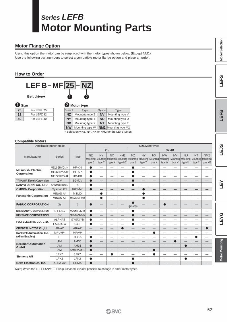
Motor Flange Option
NZMF 25BLEF
Belt drive
How to Order
Series LEFB
Motor Mounting Parts
q Size w Motor type
q w
25 For LEF�25
32 For LEF�32
40 For LEF�40
Symbol Type
NZ Mounting type Z
NY Mounting type Y
NX Mounting type X
NW Mounting type W
Compatible Motors
Using this option the motor can be renplaced with the motor types shown below. (Except NM1)
Use the following part numbers to select a compatible motor fl ange option and place an order.
∗ Select only NZ, NY, NX or NM2 for the LEFB-MF25.
Symbol Type
NV Mounting type V
NU Mounting type U
NT Mounting type T
NM2 Mounting type M2
Applicable motor model Size/Motor type
Manufacturer Series Type
25 32/40
NZ
Mounting
type Z
NY
Mounting
type Y
NX
Mounting
type X
NM2
Mounting
type M2
NZ
Mounting
type Z
NY
Mounting
type Y
NX
Mounting
type X
NW
Mounting
type W
NV
Mounting
type V
NU
Mounting
type U
NT
Mounting
type T
NM2
Mounting
type M2
Mitsubishi Electric
Corporation
MELSERVO-JN HF-KN � — — — � — — — — — — —
MELSERVO-J3 HF-KP � — — — � — — — — — — —
MELSERVO-J4 HG-KR � — — — � — — — — — — —
YASKAWA Electric Corporation Σ-V SGMJV � — — — � — — — — — — —
SANYO DENKI CO., LTD. SANMOTION R R2 � — — — � — — — — — — —
OMRON Corporation Sysmac G5 R88M-K � — — — — � — — — — — —
Panasonic CorporationMINAS-A4 MSMD — � — — — � — — — — — —
MINAS-A5 MSMD/MHMD — � — — — � — — — — — —
FANUC CORPORATION βis β � — — —�
(β1 only)— — � — — — —
NIDEC SANKYO CORPORATION S-FLAG MA/MH/MM � — — — � — — — — — — —
KEYENCE CORPORATION SV SV-M/SV-B � — — — � — — — — — — —
FUJI ELECTRIC CO., LTD.ALPHA5 GYS/GYB � — — — � — — — — — — —
FALDIC-α GYS � — — — � — — — — — — —
ORIENTAL MOTOR Co., Ltd. AR/AZ AR/AZ — — — � — — — — — — — �
Rockwell Automation, Inc.
(Allen-Bradley)
MP-/VP- MP/VP — — — — — — � — — — — —
TL TLY-A � — — — — — — — — — � —
Beckhoff Automation
GmbH
AM AM30 � — — — — — — — � — — —
AM AM31 � — — — — — — — — � — —
AM AM80/AM81 � — — — — — � — — — — —
Siemens AG1FK7 1FK7 — — � — — — � — — — — —
1FK2 1FK2 � — — — � — — — — � — —
Delta Electronics, Inc. ASDA-A2 ECMA � — — — � — — — — — — —
Note) When the LEF�25NM1�-� is purchased, it is not possible to change to other motor types.
52
LE
JS
LE
YL
EY
GL
EF
SL
EF
BM
od
el
Se
lec
tio
nM
oto
r M
ou
nti
ng
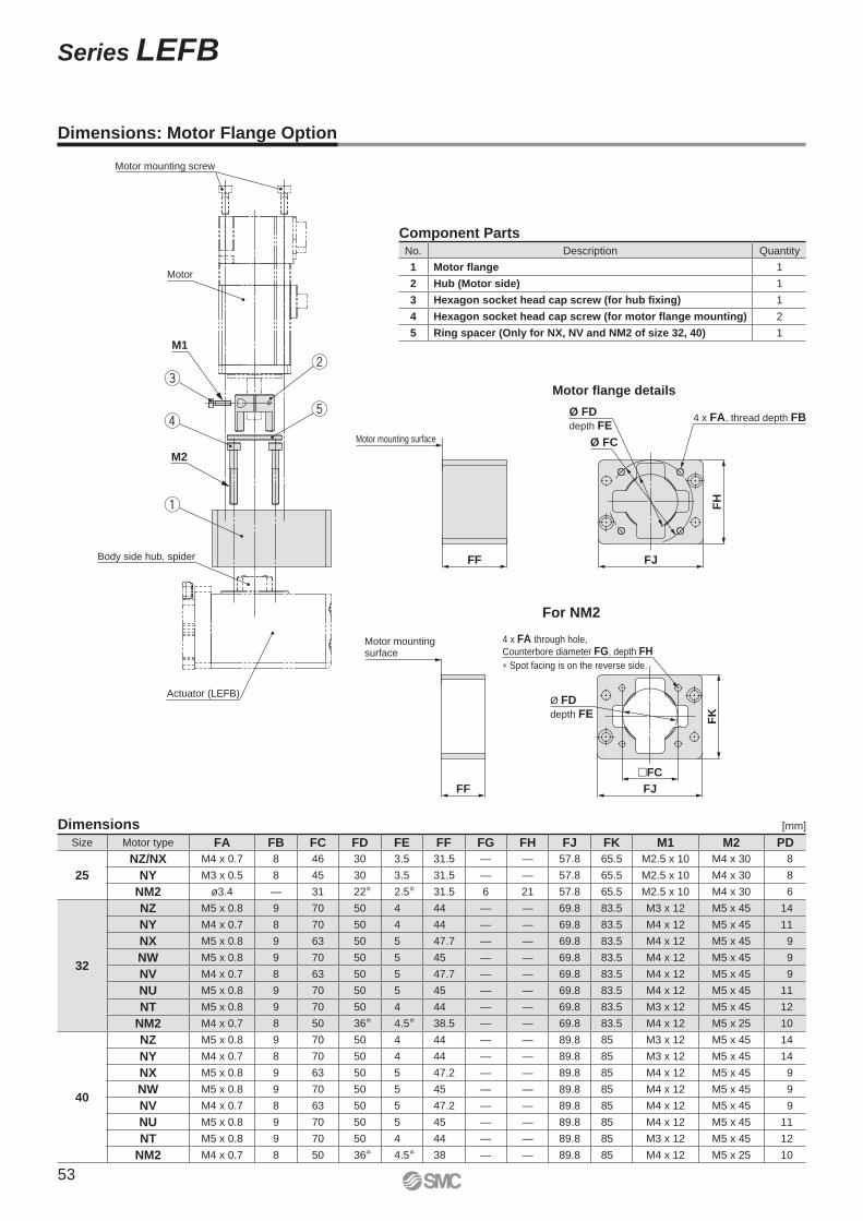
Motor mounting screw
Motor
M1
M2
Body side hub, spider
Actuator (LEFB)
Ø FD
depth FE
Ø FC
4 x FA, thread depth FB
Motor mounting surface
FF FJ
FH
Motor fl ange details
Dimensions: Motor Flange Option
Size Motor type FA FB FC FD FE FF FG FH FJ FK M1 M2 PD
25
NZ/NX M4 x 0.7 8 46 30 3.5 31.5 — — 57.8 65.5 M2.5 x 10 M4 x 30 8
NY M3 x 0.5 8 45 30 3.5 31.5 — — 57.8 65.5 M2.5 x 10 M4 x 30 8
NM2 ø3.4 — 31 22∗ 2.5∗ 31.5 6 21 57.8 65.5 M2.5 x 10 M4 x 30 6
32
NZ M5 x 0.8 9 70 50 4 44 — — 69.8 83.5 M3 x 12 M5 x 45 14
NY M4 x 0.7 8 70 50 4 44 — — 69.8 83.5 M4 x 12 M5 x 45 11
NX M5 x 0.8 9 63 50 5 47.7 — — 69.8 83.5 M4 x 12 M5 x 45 9
NW M5 x 0.8 9 70 50 5 45 — — 69.8 83.5 M4 x 12 M5 x 45 9
NV M4 x 0.7 8 63 50 5 47.7 — — 69.8 83.5 M4 x 12 M5 x 45 9
NU M5 x 0.8 9 70 50 5 45 — — 69.8 83.5 M4 x 12 M5 x 45 11
NT M5 x 0.8 9 70 50 4 44 — — 69.8 83.5 M3 x 12 M5 x 45 12
NM2 M4 x 0.7 8 50 36∗ 4.5∗ 38.5 — — 69.8 83.5 M4 x 12 M5 x 25 10
40
NZ M5 x 0.8 9 70 50 4 44 — — 89.8 85 M3 x 12 M5 x 45 14
NY M4 x 0.7 8 70 50 4 44 — — 89.8 85 M3 x 12 M5 x 45 14
NX M5 x 0.8 9 63 50 5 47.2 — — 89.8 85 M4 x 12 M5 x 45 9
NW M5 x 0.8 9 70 50 5 45 — — 89.8 85 M4 x 12 M5 x 45 9
NV M4 x 0.7 8 63 50 5 47.2 — — 89.8 85 M4 x 12 M5 x 45 9
NU M5 x 0.8 9 70 50 5 45 — — 89.8 85 M4 x 12 M5 x 45 11
NT M5 x 0.8 9 70 50 4 44 — — 89.8 85 M3 x 12 M5 x 45 12
NM2 M4 x 0.7 8 50 36∗ 4.5∗ 38 — — 89.8 85 M4 x 12 M5 x 25 10
For NM2
Dimensions [mm]
Component PartsNo. Description Quantity
1 Motor flange 1
2 Hub (Motor side) 1
3 Hexagon socket head cap screw (for hub fixing) 1
4 Hexagon socket head cap screw (for motor flange mounting) 2
5 Ring spacer (Only for NX, NV and NM2 of size 32, 40) 1
FF FJ
�FC
4 x FA through hole,
Counterbore diameter FG, depth FH
∗ Spot facing is on the reverse side.
Ø FD
depth FEF
K
Motor mounting surface
53
Series LEFB
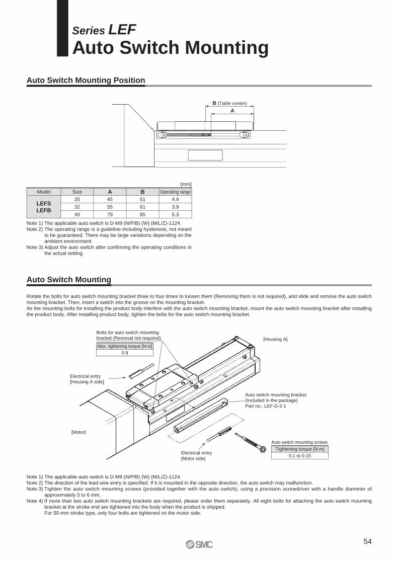
Rotate the bolts for auto switch mounting bracket three to four times to loosen them (Removing them is not required), and slide and remove the auto switch
mounting bracket. Then, insert a switch into the groove on the mounting bracket.
As the mounting bolts for installing the product body interfere with the auto switch mounting bracket, mount the auto switch mounting bracket after installing
the product body. After installing product body, tighten the bolts for the auto switch mounting bracket.
Series LEF
Auto Switch Mounting
Auto Switch Mounting Position
Auto Switch Mounting
[mm]
Model Size A B Operating range
LEFS
LEFB
25 45 51 4.9
32 55 61 3.9
40 79 85 5.3
Note 1) The applicable auto switch is D-M9 (N/P/B) (W) (M/L/Z)-1124.
Note 2) The operating range is a guideline including hysteresis, not meant
to be guaranteed. There may be large variations depending on the
ambient environment.
Note 3) Adjust the auto switch after confi rming the operating conditions in
the actual setting.
Note 1) The applicable auto switch is D-M9 (N/P/B) (W) (M/L/Z)-1124.
Note 2) The direction of the lead wire entry is specifi ed. If it is mounted in the opposite direction, the auto switch may malfunction.
Note 3) Tighten the auto switch mounting screws (provided together with the auto switch), using a precision screwdriver with a handle diameter of
approximately 5 to 6 mm.
Note 4) If more than two auto switch mounting brackets are required, please order them separately. All eight bolts for attaching the auto switch mounting
bracket at the stroke end are tightened into the body when the product is shipped.
For 50-mm stroke type, only four bolts are tightened on the motor side.
B (Table center)
A
Bolts for auto switch mounting
bracket (Removal not required)
Auto switch mounting bracket
(Included in the package)
Part no.: LEF-D-2-1
Electrical entry
[Motor side]
[Motor]
Auto switch mounting screws
Electrical entry
[Housing A side]
[Housing A]
Max. tightening torque [N·m]
0.9
Tightening torque [N·m]
0.1 to 0.15
54
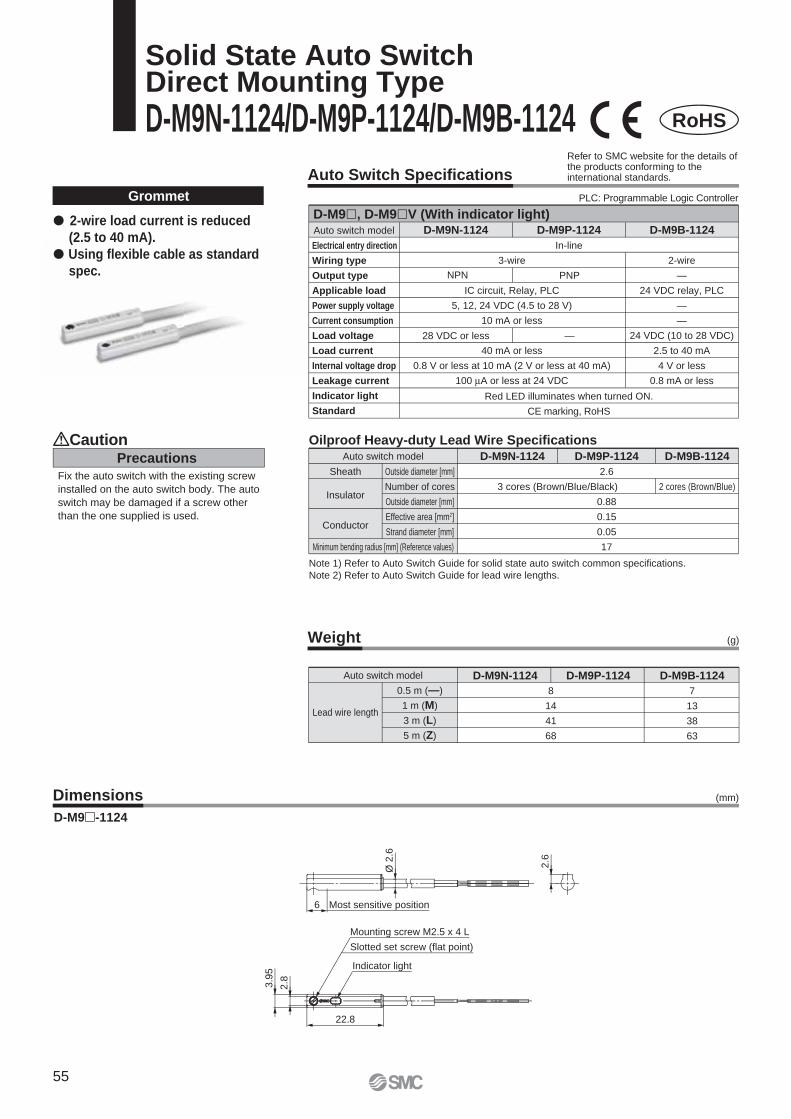
Precautions
Caution
Fix the auto switch with the existing screw
installed on the auto switch body. The auto
switch may be damaged if a screw other
than the one supplied is used.
Weight
Auto switch model
0.5 m (—)
1 m (M)
3 m (L)
5 m (Z)
8
14
41
68
D-M9P-1124 D-M9B-1124D-M9N-1124
7
13
38
63
(g)
Lead wire length
Grommet
Note 1) Refer to Auto Switch Guide for solid state auto switch common specifications.
Note 2) Refer to Auto Switch Guide for lead wire lengths.
Dimensions
D-M9�-1124
� 2-wire load current is reduced
(2.5 to 40 mA).
� Using flexible cable as standard
spec.
(mm)
2 cores (Brown/Blue)
Auto switch model D-M9N-1124 D-M9P-1124 D-M9B-1124
3 cores (Brown/Blue/Black)
Sheath
Insulator
Conductor
Outside diameter [mm]
Number of cores
Outside diameter [mm]
Effective area [mm2]
Strand diameter [mm]
Minimum bending radius [mm] (Reference values)
2.6
0.88
0.15
0.05
17
Oilproof Heavy-duty Lead Wire Specifications
RoHS
Solid State Auto SwitchDirect Mounting Type
D-M9N-1124/D-M9P-1124/D-M9B-1124
Auto Switch Specifications
Auto switch model D-M9N-1124 D-M9B-1124
2-wire
—
24 VDC relay, PLC
—
—
24 VDC (10 to 28 VDC)
2.5 to 40 mA
4 V or less
0.8 mA or less
D-M9P-1124
Red LED illuminates when turned ON.
CE marking, RoHS
3-wire
IC circuit, Relay, PLC
5, 12, 24 VDC (4.5 to 28 V)
10 mA or less
40 mA or less
0.8 V or less at 10 mA (2 V or less at 40 mA)
100 μA or less at 24 VDC
In-line
NPN PNP
28 VDC or less —
D-M9�, D-M9�V (With indicator light)
PLC: Programmable Logic Controller
Refer to SMC website for the details of the products conforming to the international standards.
Electrical entry direction
Wiring type
Output type
Applicable load
Power supply voltage
Current consumption
Load voltage
Load current
Internal voltage drop
Leakage current
Indicator light
Standard
Most sensitive position
Ø2.6
2.6
3.9
5
2.8
6
22.8
Mounting screw M2.5 x 4 L
Slotted set screw (flat point)
Indicator light
55

Weight (g)
(mm)Dimensions
Auto switch model
0.5 m (—)
1 m (M)
3 m (L)
5 m (Z)
D-M9NW-1124
8
14
41
68
D-M9PW-1124 D-M9BW-1124
7
13
38
63
Lead wire length
Grommet
Note 1) Refer to Auto Switch Guide for solid state auto switch common specifications.
Note 2) Refer to Auto Switch Guide for lead wire lengths.
� 2-wire load current is reduced
(2.5 to 40 mA).
� Using flexible cable as standard
spec.
� The proper operating range can
be determined by the color of
the light. (Red → Green ← Red)
D-M9�W-1124
RoHS
2 cores (Brown/Blue)
Auto switch model D-M9NW-1124 D-M9PW-1124 D-M9BW-1124
3 cores (Brown/Blue/Black)
Sheath
Insulator
Conductor
Outside diameter [mm]
Number of cores
Outside diameter [mm]
Effective area [mm2]
Strand diameter [mm]
Minimum bending radius [mm] (Reference values)
2.6
0.88
0.15
0.05
17
Oilproof Flexible Heavy-duty Lead Wire Specifications
2-Color Indicator Solid State Auto SwitchDirect Mounting Type
D-M9NW-1124/D-M9PW-1124/D-M9BW-1124
Precautions
Caution
Fix the auto switch with the existing screw
installed on the auto switch body. The auto
switch may be damaged if a screw other
than the one supplied is used.
Auto switch model
Electrical entry direction
Wiring type
Output type
Applicable load
Power supply voltage
Current consumption
Load voltage
Load current
Internal voltage drop
Leakage current
Indicator light
Standard
D-M9NW-1124
2-wire
—
24 VDC relay, PLC
—
—
24 VDC (10 to 28 VDC)
2.5 to 40 mA
4 V or less
0.8 mA or less
D-M9PW-1124 D-M9BW-1124
Operating range .......... Red LED illuminates.
Proper operating range .......... Green LED illuminates.
3-wire
IC circuit, Relay, PLC
5, 12, 24 VDC (4.5 to 28 V)
10 mA or less
40 mA or less
0.8 V or less at 10 mA (2 V or less at 40 mA)
100 μA or less at 24 VDC
CE marking, RoHS
In-line
NPN PNP
28 VDC or less —
D-M9�W, D-M9�WV (With indicator light)
Auto Switch Specifications
Refer to SMC website for the details of the products conforming to the international standards.
PLC: Programmable Logic Controller
6 Most sensitive position
2.6
Ø2.6
22.8
Indicator light
3.9
5
2.8
Slotted set screw (flat point)
Mounting screw M2.5 x 4 L
56
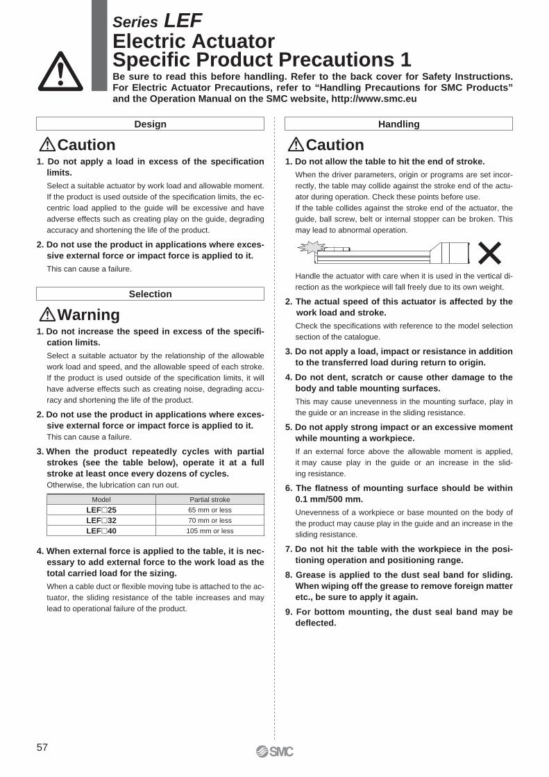
Design
Caution1. Do not apply a load in excess of the specifi cation
limits.
Select a suitable actuator by work load and allowable moment.
If the product is used outside of the specifi cation limits, the ec-
centric load applied to the guide will be excessive and have
adverse effects such as creating play on the guide, degrading
accuracy and shortening the life of the product.
2. Do not use the product in applications where exces-
sive external force or impact force is applied to it.
This can cause a failure.
Handling
Caution
Selection
Warning1. Do not increase the speed in excess of the specifi -
cation limits.
Select a suitable actuator by the relationship of the allowable
work load and speed, and the allowable speed of each stroke.
If the product is used outside of the specifi cation limits, it will
have adverse effects such as creating noise, degrading accu-
racy and shortening the life of the product.
2. Do not use the product in applications where exces-
sive external force or impact force is applied to it.
This can cause a failure.
3. When the product repeatedly cycles with partial
strokes (see the table below), operate it at a full
stroke at least once every dozens of cycles.
Otherwise, the lubrication can run out.
4. When external force is applied to the table, it is nec-
essary to add external force to the work load as the
total carried load for the sizing.
When a cable duct or fl exible moving tube is attached to the ac-
tuator, the sliding resistance of the table increases and may
lead to operational failure of the product.
1. Do not allow the table to hit the end of stroke.
When the driver parameters, origin or programs are set incor-
rectly, the table may collide against the stroke end of the actu-
ator during operation. Check these points before use.
If the table collides against the stroke end of the actuator, the
guide, ball screw, belt or internal stopper can be broken. This
may lead to abnormal operation.
Handle the actuator with care when it is used in the vertical di-
rection as the workpiece will fall freely due to its own weight.
2. The actual speed of this actuator is affected by the
work load and stroke.
Check the specifi cations with reference to the model selection
section of the catalogue.
3. Do not apply a load, impact or resistance in addition
to the transferred load during return to origin.
4. Do not dent, scratch or cause other damage to the
body and table mounting surfaces.
This may cause unevenness in the mounting surface, play in
the guide or an increase in the sliding resistance.
5. Do not apply strong impact or an excessive moment
while mounting a workpiece.
If an external force above the allowable moment is applied,
it may cause play in the guide or an increase in the slid-
ing resistance.
6. The fl atness of mounting surface should be within
0.1 mm/500 mm.
Unevenness of a workpiece or base mounted on the body of
the product may cause play in the guide and an increase in the
sliding resistance.
7. Do not hit the table with the workpiece in the posi-
tioning operation and positioning range.
8. Grease is applied to the dust seal band for sliding.
When wiping off the grease to remove foreign matter
etc., be sure to apply it again.
9. For bottom mounting, the dust seal band may be
defl ected.
Series LEFElectric ActuatorSpecifi c Product Precautions 1Be sure to read this before handling. Refer to the back cover for Safety Instructions. For Electric Actuator Precautions, refer to “Handling Precautions for SMC Products” and the Operation Manual on the SMC website, http://www.smc.eu
Model Partial stroke
LEF�25 65 mm or less
LEF�32 70 mm or less
LEF�40 105 mm or less
57
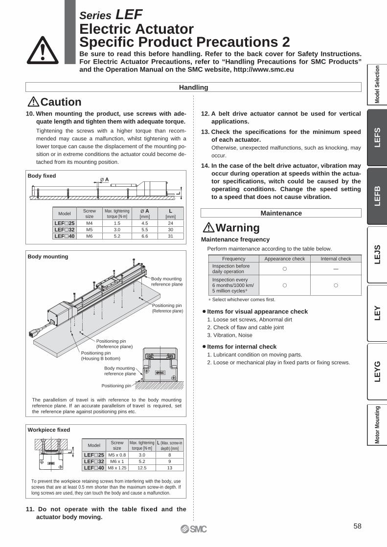
Ø AL
Body mounting
reference plane
Positioning pin
(Reference plane)
Positioning pin
(Reference plane)
Positioning pin
(Housing B bottom)
Positioning pin
Body mounting
reference plane
L
To prevent the workpiece retaining screws from interfering with the body, use
screws that are at least 0.5 mm shorter than the maximum screw-in depth. If
long screws are used, they can touch the body and cause a malfunction.
Workpiece fi xed
Body fi xed
Body mounting
The parallelism of travel is with reference to the body mounting
reference plane. If an accurate parallelism of travel is required, set
the reference plane against positioning pins etc.
Maintenance
WarningMaintenance frequency
Perform maintenance according to the table below.
¡Items for visual appearance check
1. Loose set screws, Abnormal dirt
2. Check of fl aw and cable joint
3. Vibration, Noise
¡Items for internal check
1. Lubricant condition on moving parts.
2. Loose or mechanical play in fi xed parts or fi xing screws.
∗ Select whichever comes fi rst.
Handling
Caution10. When mounting the product, use screws with ade-
quate length and tighten them with adequate torque.
Tightening the screws with a higher torque than recom-
mended may cause a malfunction, whilst tightening with a
lower torque can cause the displacement of the mounting po-
sition or in extreme conditions the actuator could become de-
tached from its mounting position.
12. A belt drive actuator cannot be used for vertical
applications.
13. Check the specifi cations for the minimum speed
of each actuator.
Otherwise, unexpected malfunctions, such as knocking, may
occur.
14. In the case of the belt drive actuator, vibration may
occur during operation at speeds within the actua-
tor specifi cations, witch could be caused by the
operating conditions. Change the speed setting
to a speed that does not cause vibration.
11. Do not operate with the table fixed and the
actuator body moving.
Series LEFElectric ActuatorSpecifi c Product Precautions 2
Frequency Appearance check Internal check
Inspection beforedaily operation
� —
Inspection every6 months/1000 km/5 million cycles∗
� �
ModelScrew
size
Max. tightening
torque [N·m]Ø A[mm]
L[mm]
LEF�25 M4 1.5 4.5 24
LEF�32 M5 3.0 5.5 30
LEF�40 M6 5.2 6.6 31
ModelScrew
size
Max. tightening
torque [N·m]L (Max. screw-in
depth) [mm]
LEF�25 M5 x 0.8 3.0 8
LEF�32 M6 x 1 5.2 9
LEF�40 M8 x 1.25 12.5 13
Be sure to read this before handling. Refer to the back cover for Safety Instructions. For Electric Actuator Precautions, refer to “Handling Precautions for SMC Products” and the Operation Manual on the SMC website, http://www.smc.eu
58
LE
FS
LE
FB
LE
JS
LE
YL
EY
GM
od
el
Se
lec
tio
nM
oto
r M
ou
nti
ng

59
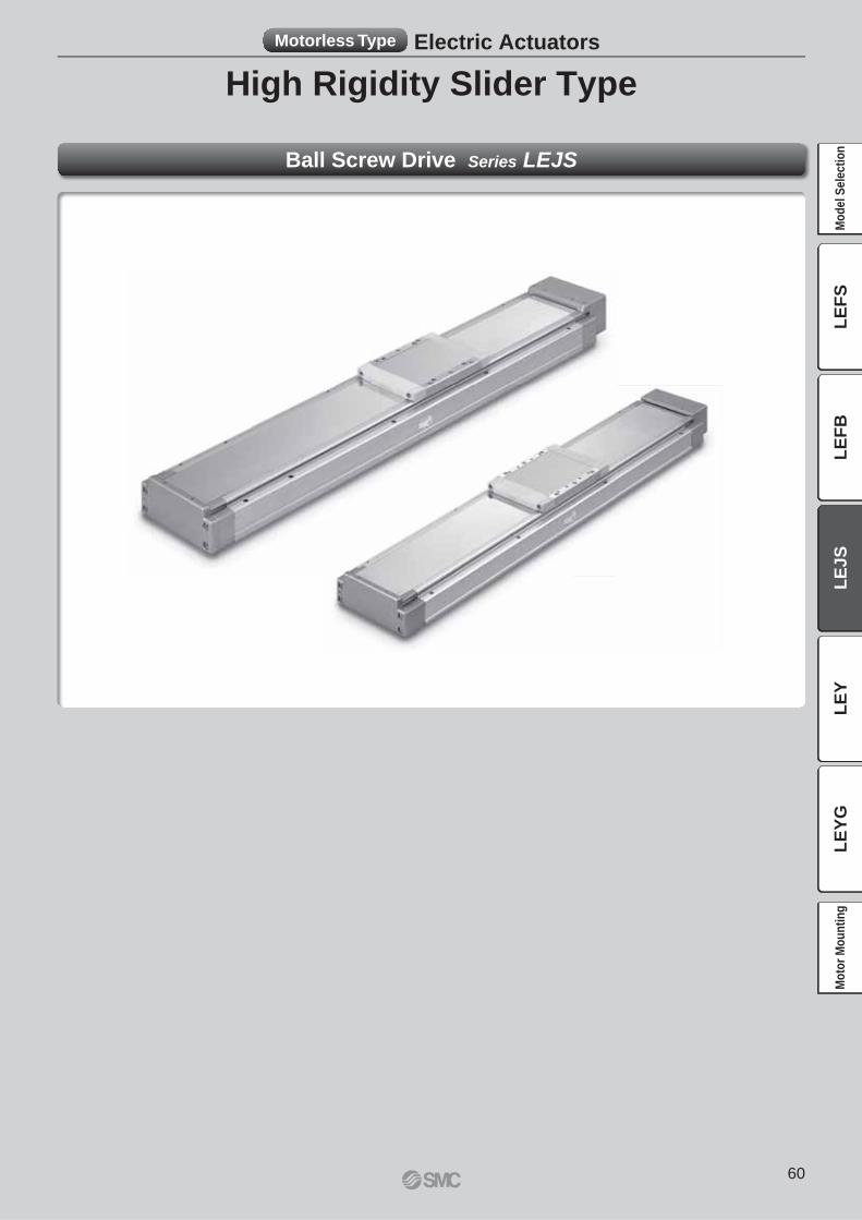
High Rigidity Slider Type
Motorless Type Electric Actuators
Ball Screw Drive Series LEJS
60
LE
FS
LE
FB
LE
JS
LE
YL
EY
GM
od
el
Se
lec
tio
nM
oto
r M
ou
nti
ng
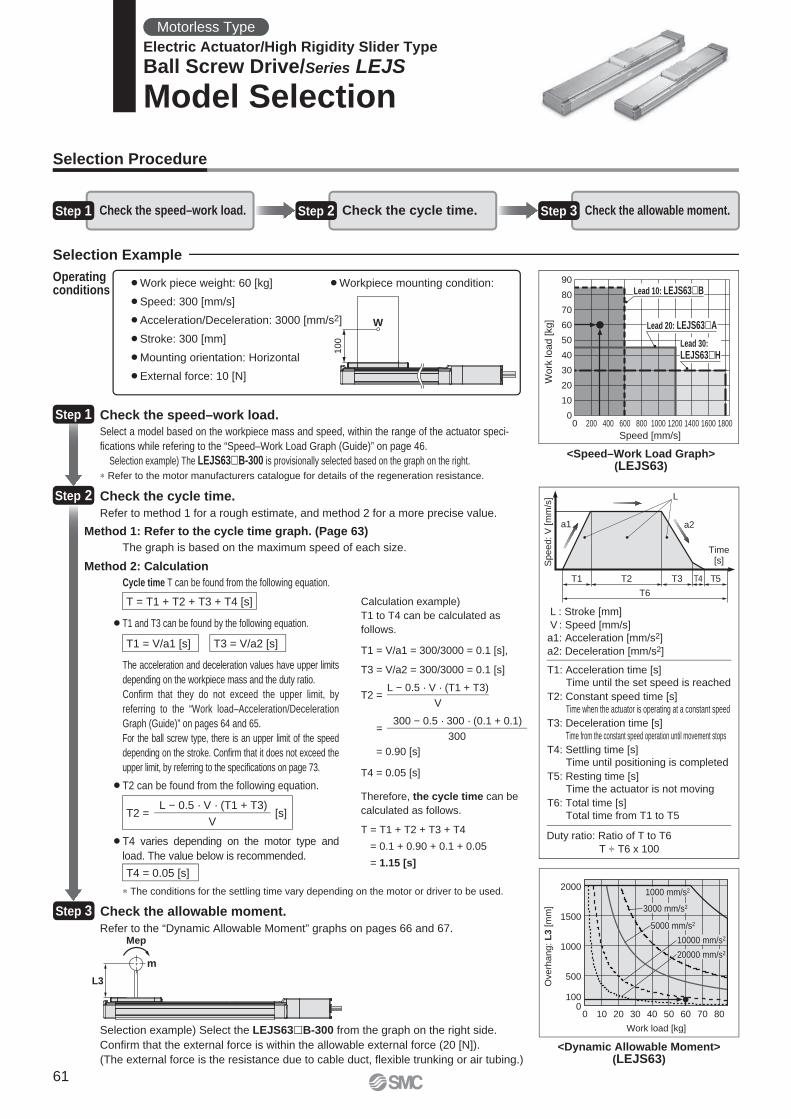
0
10
20
30
40
50
60
70
80
90
0 200 400 600 800 1000 1200 1400 1600 1800
Work
load [
kg]
Speed [mm/s]
Lead 20: LEJS63 A
Lead 10: LEJS63 B
Lead 30:
LEJS63 H
T1
a1 a2
L
Speed:
V [
mm
/s]
Time[s]
T2
T6
T3 T4 T5
L3
Mep
m
100
W
20000 mm/s2
10000 mm/s2
5000 mm/s2
3000 mm/s2
1000 mm/s2
Overh
ang:
L3
[m
m]
Work load [kg]
0
500
1000
1500
2000
0 10 20 30 40 50 60 70 80
100
Selection Procedure
Selection Example
Step 1 Check the speed–work load. Step 2 Check the cycle time. Step 3 Check the allowable moment.
¡Work piece weight: 60 [kg]
¡Speed: 300 [mm/s]
¡Acceleration/Deceleration: 3000 [mm/s2]
¡Stroke: 300 [mm]
¡Mounting orientation: Horizontal
¡External force: 10 [N]
¡Workpiece mounting condition:Operating conditions
<Speed–Work Load Graph>(LEJS63)
Step 1 Check the speed–work load.
Select a model based on the workpiece mass and speed, within the range of the actuator speci-
fi cations while refering to the “Speed–Work Load Graph (Guide)” on page 46.
Selection example) The LEJS63�B-300 is provisionally selected based on the graph on the right.
Step 2 Check the cycle time.
Method 2: Calculation
Refer to method 1 for a rough estimate, and method 2 for a more precise value.
Cycle time T can be found from the following equation.
Method 1: Refer to the cycle time graph. (Page 63)
The graph is based on the maximum speed of each size.
T = T1 + T2 + T3 + T4 [s]
T4 = 0.05 [s]
T1 = V/a1 [s] T3 = V/a2 [s]
T2 = [s]L − 0.5 · V · (T1 + T3)
V
¡T4 varies depending on the motor type and
load. The value below is recommended.
¡T2 can be found from the following equation.
¡T1 and T3 can be found by the following equation.
The acceleration and deceleration values have upper limits
depending on the workpiece mass and the duty ratio.
Confi rm that they do not exceed the upper limit, by
referring to the “Work load–Acceleration/Deceleration
Graph (Guide)” on pages 64 and 65.
For the ball screw type, there is an upper limit of the speed
depending on the stroke. Confi rm that it does not exceed the
upper limit, by referring to the specifi cations on page 73.
Step 3 Check the allowable moment.
<Dynamic Allowable Moment>(LEJS63)
L : Stroke [mm]
V : Speed [mm/s]
a1: Acceleration [mm/s2]
a2: Deceleration [mm/s2]
Duty ratio: Ratio of T to T6
T ÷ T6 x 100
T1: Acceleration time [s]Time until the set speed is reached
T2: Constant speed time [s]Time when the actuator is operating at a constant speed
T3: Deceleration time [s]Time from the constant speed operation until movement stops
T4: Settling time [s]Time until positioning is completed
T5: Resting time [s]Time the actuator is not moving
T6: Total time [s]Total time from T1 to T5
Calculation example)
T1 to T4 can be calculated as
follows.
T1 = V/a1 = 300/3000 = 0.1 [s],
T3 = V/a2 = 300/3000 = 0.1 [s]
T4 = 0.05 [s]
Therefore, the cycle time can be
calculated as follows.
T = T1 + T2 + T3 + T4
= 0.1 + 0.90 + 0.1 + 0.05
= 1.15 [s]
T2 =
=
= 0.90 [s]
L − 0.5 · V · (T1 + T3)
V
300 − 0.5 · 300 · (0.1 + 0.1)
300
Refer to the “Dynamic Allowable Moment” graphs on pages 66 and 67.
Selection example) Select the LEJS63�B-300 from the graph on the right side.
Confi rm that the external force is within the allowable external force (20 [N]).
(The external force is the resistance due to cable duct, fl exible trunking or air tubing.)
∗ The conditions for the settling time vary depending on the motor or driver to be used.
∗ Refer to the motor manufacturers catalogue for details of the regeneration resistance.
Motorless Type
Electric Actuator/High Rigidity Slider Type
Ball Screw Drive/Series LEJS
Model Selection
61
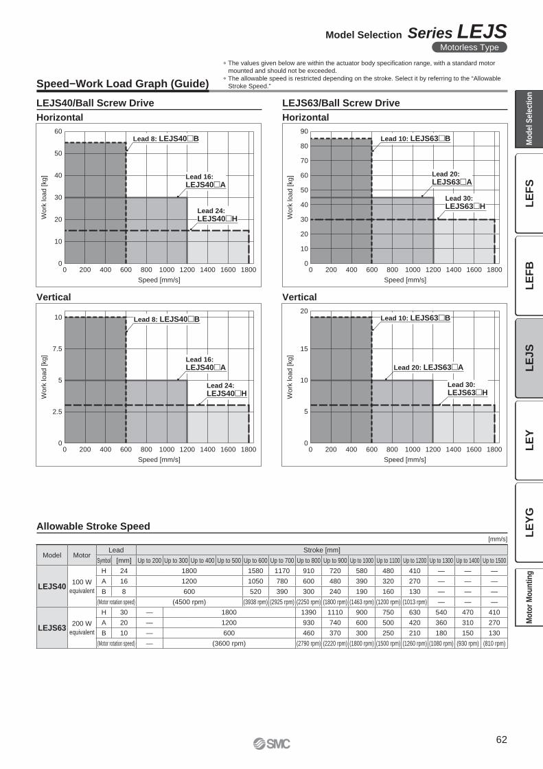
Work
load [
kg]
Speed [mm/s]
0
10
20
30
40
50
60
0 200 400 600 800 1000 1200 1400 1600 1800
Lead 16:
LEJS40 A
Lead 8: LEJS40 B
Lead 24:
LEJS40 H
10
20
30
40
50
60
70
80
90
0 200 400 600 800 1000 1200 1400 1600 1800
Work
load [
kg]
Speed [mm/s]
0
Lead 20:
LEJS63 A
Lead 10: LEJS63 B
Lead 30:
LEJS63 H
0 200 400 600 800 1000 1200 1400 1600 18000
5
10
7.5
2.5
Wo
rk lo
ad
[kg
]
Speed [mm/s]
Lead 16:
LEJS40 A
Lead 8: LEJS40 B
Lead 24:
LEJS40 H
5
10
15
20
0 200 400 600 800 1000 1200 1400 1600 1800
Wo
rk lo
ad
[kg
]
Speed [mm/s]
0
Lead 20: LEJS63 A
Lead 10: LEJS63 B
Lead 30:
LEJS63 H
Speed−Work Load Graph (Guide)
∗ The values given below are within the actuator body specifi cation range, with a standard motor
mounted and should not be exceeded.
∗ The allowable speed is restricted depending on the stroke. Select it by referring to the “Allowable
Stroke Speed.”
LEJS40/Ball Screw Drive LEJS63/Ball Screw Drive
Horizontal Horizontal
Vertical Vertical
Allowable Stroke Speed[mm/s]
Model MotorLead Stroke [mm]
Symbol [mm] Up to 200 Up to 300 Up to 400 Up to 500 Up to 600 Up to 700 Up to 800 Up to 900 Up to 1000 Up to 1100 Up to 1200 Up to 1300 Up to 1400 Up to 1500
LEJS40100 W
equivalent
H 24 1800 1580 1170 910 720 580 480 410 — — —
A 16 1200 1050 780 600 480 390 320 270 — — —
B 8 600 520 390 300 240 190 160 130 — — —
(Motor rotation speed) (4500 rpm) (3938 rpm) (2925 rpm) (2250 rpm) (1800 rpm) (1463 rpm) (1200 rpm) (1013 rpm) — — —
LEJS63200 W
equivalent
H 30 — 1800 1390 1110 900 750 630 540 470 410
A 20 — 1200 930 740 600 500 420 360 310 270
B 10 — 600 460 370 300 250 210 180 150 130
(Motor rotation speed) — (3600 rpm) (2790 rpm) (2220 rpm) (1800 rpm) (1500 rpm) (1260 rpm) (1080 rpm) (930 rpm) (810 rpm)
62
Model Selection Series LEJSMotorless Type
LE
FS
LE
FB
LE
JS
LE
YL
EY
GM
od
el
Se
lec
tio
nM
oto
r M
ou
nti
ng
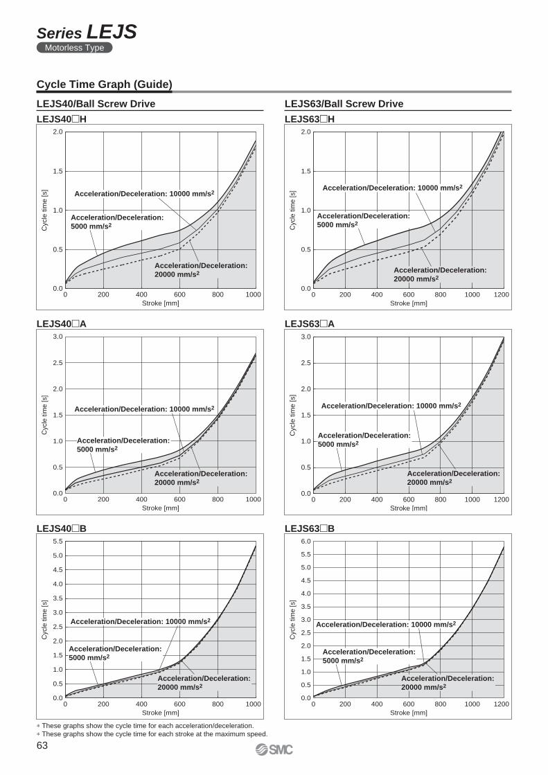
Acceleration/Deceleration: 10000 mm/s2
Acceleration/Deceleration:
20000 mm/s2
Acceleration/Deceleration:
5000 mm/s2
Cyc
le tim
e [s]
Stroke [mm]
0 1200200 400 600 800 10000.0
0.5
1.0
1.5
2.0
Cycle
tim
e [s]
Stroke [mm]
0 12001000200 400 600 8000.0
0.5
1.0
1.5
2.0
2.5
3.0
Acceleration/Deceleration:
5000 mm/s2
Acceleration/Deceleration: 10000 mm/s2
Acceleration/Deceleration:
20000 mm/s2
Cyc
le tim
e [s]
Stroke [mm]
0 1200200 400 600 800 10000.0
0.5
1.0
1.5
2.0
2.5
3.0
3.5
4.0
4.5
5.0
5.5
6.0
Acceleration/Deceleration:
5000 mm/s2
Acceleration/Deceleration: 10000 mm/s2
Acceleration/Deceleration:
20000 mm/s2
Acceleration/Deceleration: 10000 mm/s2
Acceleration/Deceleration:
20000 mm/s2
1000200 400 600 800
Acceleration/Deceleration:
5000 mm/s2
Cycle
tim
e [
s]
Stroke [mm]
00.0
0.5
1.0
1.5
2.0
Cyc
le t
ime
[s]
Stroke [mm]
0 1000200 400 600 8000.0
0.5
1.0
1.5
2.0
2.5
3.0
Acceleration/Deceleration:
5000 mm/s2
Acceleration/Deceleration: 10000 mm/s2
Acceleration/Deceleration:
20000 mm/s2
Cyc
le t
ime
[s]
Stroke [mm]
0 1000200 400 600 8000.0
0.5
1.0
1.5
2.0
2.5
3.0
3.5
4.0
4.5
5.0
5.5
Acceleration/Deceleration:
5000 mm/s2
Acceleration/Deceleration: 10000 mm/s2
Acceleration/Deceleration:
20000 mm/s2
Cycle Time Graph (Guide)
LEJS40/Ball Screw Drive LEJS63/Ball Screw Drive
LEJS40�H LEJS63�H
∗ These graphs show the cycle time for each acceleration/deceleration.
∗ These graphs show the cycle time for each stroke at the maximum speed.
LEJS40�A
LEJS40�B
LEJS63�A
LEJS63�B
63
Series LEJSMotorless Type
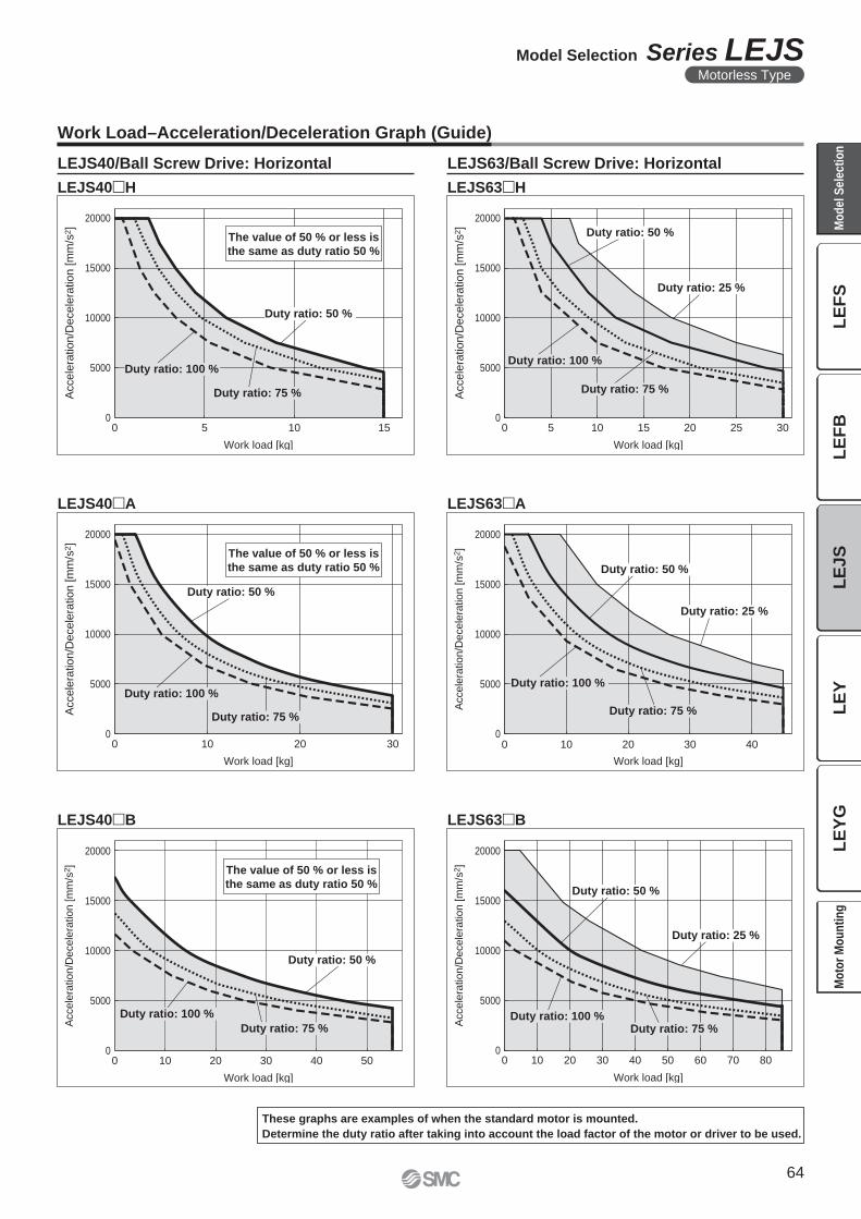
0
5000
10000
15000
20000
0 5 10 15
Work load [kg]
Accele
ration/D
ecele
ration [m
m/s
2]
Duty ratio: 100 %
Duty ratio: 75 %
Duty ratio: 50 %
The value of 50 % or less is
the same as duty ratio 50 %
0
5000
10000
15000
20000
0 5 10 20 3015 25
Work load [kg]
Accele
ration/D
ecele
ration [m
m/s
2]
Duty ratio: 100 %
Duty ratio: 75 %
Duty ratio: 50 %
Duty ratio: 25 %
5000
10000
15000
20000
0 10 20 30
Work load [kg]
Accele
ration/D
ecele
ration [m
m/s
2]
Duty ratio: 100 %
Duty ratio: 75 %
Duty ratio: 50 %
0
The value of 50 % or less is
the same as duty ratio 50 %
0
5000
10000
15000
20000
0 10 20 30 40
Work load [kg]
Accele
ration/D
ecele
ration [m
m/s
2]
Duty ratio: 100 %
Duty ratio: 50 %
Duty ratio: 25 %
Duty ratio: 75 %
0
5000
10000
15000
20000
0 10 20 30 40 50
Work load [kg]
Accele
ration/D
ecele
ration [m
m/s
2]
Duty ratio: 100 %
Duty ratio: 50 %
Duty ratio: 75 %
The value of 50 % or less is
the same as duty ratio 50 %
0
5000
10000
15000
20000
0 10 20 30 40 50 60 70 80
Work load [kg]
Accele
ration/D
ecele
ration [m
m/s
2]
Duty ratio: 100 %
Duty ratio: 50 %
Duty ratio: 25 %
Duty ratio: 75 %
Work Load–Acceleration/Deceleration Graph (Guide)
LEJS40/Ball Screw Drive: Horizontal
LEJS40�H LEJS63�H
LEJS63/Ball Screw Drive: Horizontal
LEJS40�A LEJS63�A
LEJS40�B LEJS63�B
These graphs are examples of when the standard motor is mounted.
Determine the duty ratio after taking into account the load factor of the motor or driver to be used.
64
Model Selection Series LEJSMotorless Type
LE
FS
LE
FB
LE
JS
LE
YL
EY
GM
od
el
Se
lec
tio
nM
oto
r M
ou
nti
ng
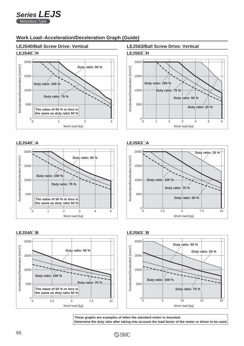
0
5000
10000
15000
20000
0 1 2 3
Work load [kg]
Accele
ration/D
ecele
ration [m
m/s
2]
Duty ratio: 100 %
Duty ratio: 50 %
Duty ratio: 75 %
The value of 50 % or less is
the same as duty ratio 50 %
0
5000
10000
15000
20000
0 1 2 3 4 5 6
Work load [kg]
Accele
ration/D
ecele
ration [m
m/s
2]
Duty ratio: 100 %
Duty ratio: 50 %
Duty ratio: 25 %
Duty ratio: 75 %
0 1 2 3 4 50
5000
10000
15000
20000
Work load [kg]
Accele
ration/D
ecele
ration [m
m/s
2]
Duty ratio: 100 %
Duty ratio: 50 %
Duty ratio: 75 %
The value of 50 % or less is
the same as duty ratio 50 %
0
5000
10000
15000
20000
0 2.5 5 7.5 10
Work load [kg]
Accele
ration/D
ecele
ration [m
m/s
2]
Duty ratio: 100 %
Duty ratio: 25 %
Duty ratio: 75 %
Duty ratio: 50 %
0
5000
10000
15000
20000
0 2.5 5 7.5 10
Work load [kg]
Accele
ration/D
ecele
ration [m
m/s
2]
Duty ratio: 100 %
Duty ratio: 50 %
Duty ratio: 75 %
The value of 50 % or less is
the same as duty ratio 50 %
0
5000
10000
15000
20000
0 5 10 15 20
Work load [kg]
Accele
ration/D
ecele
ration [m
m/s
2] Duty ratio: 50 %
Duty ratio: 25 %
Duty ratio: 75 %
Duty ratio: 100 %
Work Load–Acceleration/Deceleration Graph (Guide)
LEJS40�H LEJS63�H
LEJS40/Ball Screw Drive: Vertical LEJS63/Ball Screw Drive: Vertical
LEJS40�A LEJS63�A
LEJS40�B LEJS63�B
These graphs are examples of when the standard motor is mounted.
Determine the duty ratio after taking into account the load factor of the motor or driver to be used.
65
Series LEJSMotorless Type
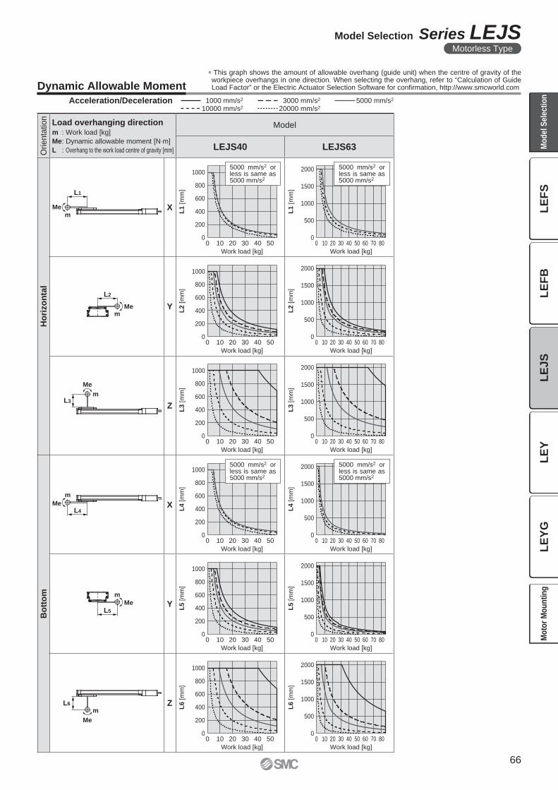
m
Me
L1
L2
mMe
m
Me
L3
0
200
400
600
800
1000
0
500
1000
1500
2000
L1
[m
m]
L1
[m
m]
0 10 40 5020 300 10 40 5020 30 60 70 80
0
200
400
600
800
1000
0
500
1000
1500
2000
L2
[m
m]
L2
[m
m]
0 10 40 5020 300 10 40 5020 30 60 70 80
0
200
400
600
800
1000
0
500
1000
1500
2000
L3 [
mm
]
L3 [
mm
]
0 10 40 5020 300 10 40 5020 30 60 70 80
0
200
400
600
800
1000
0
500
1000
1500
2000
L4 [
mm
]
L4 [
mm
]
0 10 40 5020 300 10 40 5020 30 60 70 80
0
200
400
600
800
1000
0
500
1000
1500
2000
L5
[m
m]
L5
[m
m]
0 10 40 5020 300 10 40 5020 30 60 70 80
0
200
400
600
800
1000
0
500
1000
1500
2000
Work load [kg]
L6 [m
m]
Work load [kg]
Work load [kg]Work load [kg]
Work load [kg]Work load [kg]
Work load [kg]Work load [kg]
Work load [kg]Work load [kg]
Work load [kg]Work load [kg]
L6 [m
m]
0 10 40 5020 300 10 40 5020 30 60 70 80
5000 mm/s2 or less is same as 5000 mm/s2
5000 mm/s2 or less is same as 5000 mm/s2
5000 mm/s2 or less is same as 5000 mm/s2
5000 mm/s2 or less is same as 5000 mm/s2
m
MeL4
L5
m
Me
m
Me
L6
Orienta
tion
Load overhanging directionm : Work load [kg]
Me: Dynamic allowable moment [N·m]
L : Overhang to the work load centre of gravity [mm]
Model
LEJS40 LEJS63
Ho
rizo
nta
l
X
Y
Z
Bo
tto
m
X
Y
Z
Acceleration/Deceleration 1000 mm/s2 5000 mm/s2
10000 mm/s2
3000 mm/s2
20000 mm/s2
Dynamic Allowable Moment
∗ This graph shows the amount of allowable overhang (guide unit) when the centre of gravity of the workpiece overhangs in one direction. When selecting the overhang, refer to “Calculation of Guide Load Factor” or the Electric Actuator Selection Software for confi rmation, http://www.smcworld.com
66
Model Selection Series LEJSMotorless Type
LE
FS
LE
FB
LE
JS
LE
YL
EY
GM
od
el
Se
lec
tio
nM
oto
r M
ou
nti
ng
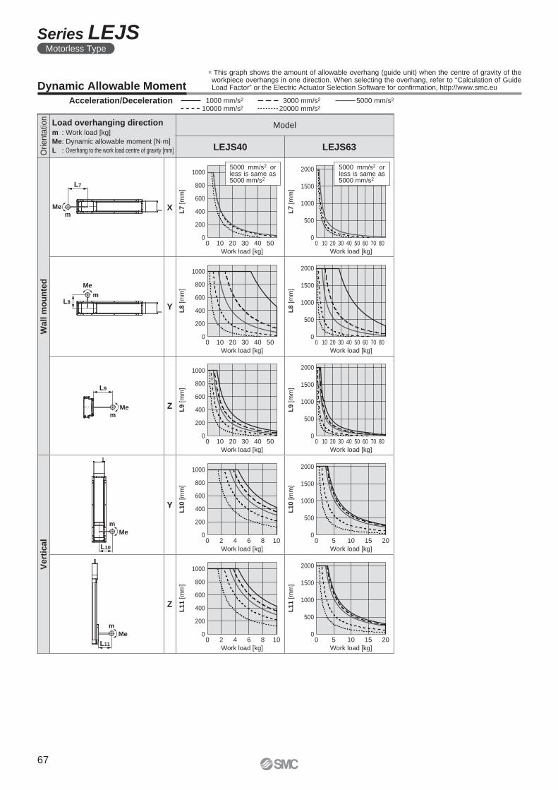
m
Me
L10
m
Me
L11
0
200
400
600
800
1000
0
500
1000
1500
2000
L7
[m
m]
L7
[m
m]
0 10 40 5020 300 10 40 5020 30 60 70 80
0
200
400
600
800
1000
0
500
1000
1500
2000
L8
[m
m]
L8
[m
m]
0 10 40 5020 300 10 40 5020 30 60 70 80
0
200
400
600
800
1000
0
500
1000
1500
2000
L9 [
mm
]
L9 [
mm
]
0 10 40 5020 300 10 40 5020 30 60 70 80
0
200
400
600
800
1000
0
500
1000
1500
2000
L10 [
mm
]
L10 [
mm
]
0 10 155 20
0 10 155 20
0 2 8 104 6
0 2 8 104 60
200
400
600
800
1000
0
500
1000
1500
2000
L11
[m
m]
L11
[m
m]
Work load [kg]Work load [kg]
Work load [kg]Work load [kg]
Work load [kg]Work load [kg]
Work load [kg]Work load [kg]
Work load [kg]Work load [kg]
5000 mm/s2 or less is same as 5000 mm/s2
5000 mm/s2 or less is same as 5000 mm/s2
L7
m
Me
m
Me
L8
L9
mMe
Orienta
tion
Load overhanging directionm : Work load [kg]
Me: Dynamic allowable moment [N·m]
L : Overhang to the work load centre of gravity [mm]
Model
LEJS40 LEJS63
Wall
mo
un
ted
X
Y
Z
Vert
ical
Y
Z
Dynamic Allowable Moment
∗ This graph shows the amount of allowable overhang (guide unit) when the centre of gravity of the workpiece overhangs in one direction. When selecting the overhang, refer to “Calculation of Guide Load Factor” or the Electric Actuator Selection Software for confi rmation, http://www.smc.eu
Acceleration/Deceleration 1000 mm/s2 5000 mm/s2
10000 mm/s2
3000 mm/s2
20000 mm/s2
67
Series LEJSMotorless Type
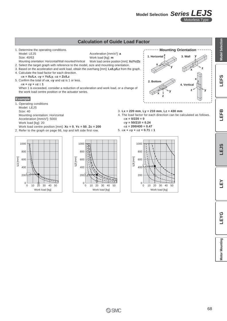
xy
z
x z
y
xy
z
x
z y
0
200
400
600
800
1000
L1 [
mm
]
0 10 20 30 40 50
Work load [kg]
Lx
0
200
400
600
800
1000
L2 [
mm
]
0 10 20 30 40 50
Work load [kg]
Ly
0
600
800
1000
L3 [
mm
]
200
400
0 10 20 30 40 50
Work load [kg]
Lz
Calculation of Guide Load Factor
1. Determine the operating conditions.
Model: LEJS
Size: 40/63
Mounting orientation: Horizontal/Wall mounted/Vertical
2. Select the target graph with reference to the model, size and mounting orientation.
3. Based on the acceleration and work load, obtain the overhang [mm]: Lx/Ly/Lz from the graph.
4. Calculate the load factor for each direction.
αx = Xc/Lx, αy = Yc/Ly, αz = Zc/Lz
5. Confi rm the total of αx, αy and αz is 1 or less.
αx + αy + αz ≤ 1
When 1 is exceeded, consider a reduction of acceleration and work load, or a change of
the work load centre position or the actuator series.
1. Operating conditions
Model: LEJS
Size: 40
Mounting orientation: Horizontal
Acceleration [mm/s2]: 5000
Work load [kg]: 20
Work load centre position [mm]: Xc = 0, Yc = 50, Zc = 200
2. Refer to the graph on page 66, top and left side fi rst row.
Example
Acceleration [mm/s2]: a
Work load [kg]: m
Work load centre position [mm]: Xc/Yc/Zc
Mounting Orientation
1. Horizontal 3. Wall
2. Bottom4. Vertical
3. Lx = 220 mm, Ly = 210 mm, Lz = 430 mm
4. The load factor for each direction can be calculated as follows.
αx = 0/220 = 0
αy = 50/210 = 0.24
αz = 200/430 = 0.47
5. αx + αy + αz = 0.71 ≤ 1
68
Model Selection Series LEJSMotorless Type
LE
FS
LE
FB
LE
JS
LE
YL
EY
GM
od
el
Se
lec
tio
nM
oto
r M
ou
nti
ng
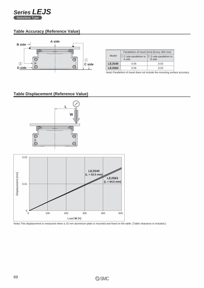
A side
C sideD side
B side
W
L
0.02
0.01
00 100 200 300 400 500
Dis
pla
cem
ent [m
m]
Load W [N]
LEJS40(L = 52.5 mm)
LEJS63(L = 64.5 mm)
Table Accuracy (Reference Value)
Note) Parallelism of travel does not include the mounting surface accuracy.
Model
Parallelism of travel [mm] (Every 300 mm)
q C side parallelism to A side
w D side parallelism to B side
LEJS40 0.05 0.03
LEJS63 0.05 0.03
Table Displacement (Reference Value)
Note) This displacement is measured when a 15 mm aluminium plate is mounted and fi xed on the table. (Table clearance is included.)
69
Series LEJSMotorless Type
70
LE
FS
LE
FB
LE
JS
LE
YL
EY
GM
od
el
Se
lec
tio
nM
oto
r M
ou
nti
ng
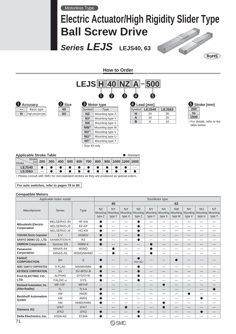
Compatible Motors
Applicable motor model Size/Motor type
Manufacturer Series Type
40 63
NZ
Mounting
type Z
NY
Mounting
type Y
NX
Mounting
type X
NZ
Mounting
type Z
NY
Mounting
type Y
NX
Mounting
type X
NW
Mounting
type W
NV
Mounting
type V
NU
Mounting
type U
NT
Mounting
type T
Mitsubishi Electric
Corporation
MELSERVO-JN HF-KN � — — � — — — — — —
MELSERVO-J3 KF-KP � — — � — — — — — —
MELSERVO-J4 HG-KR � — — � — — — — — —
YASKAWA Electric Corporation Σ-V SGMJV � — — � — — — — — —
SANYO DENKI CO., LTD. SANMOTION R R2 � — — � — — — — — —
OMRON Corporation Sysmac G5 R88M-K � — — — � — — — — —
Panasonic
Corporation
MINAS-A4 MSMD — � — — � — — — — —
MINAS-A5 MSMD/MHMD — � — — � — — — — —
FANUC
CORPORATIONβis β � — —
�(nur β1)
— — � — — —
NIDEC SANKYO CORPORATION S-FLAG MA/MH/MM � — — � — — — — — —
KEYENCE CORPORATION SV SV-M/SV-B � — — � — — — — — —
FUJI ELECTRIC CO.,
LTD.
ALPHA5 GYS/GYB � — — � — — — — — —
FALDIC-α GYS � — — � — — — — — —
Rockwell Automation, Inc.
(Allen-Bradley)
MP-/VP- MP/VP — — — — — � — — — —
TL TLY-A � — — — — — — — — �
Beckhoff Automation
GmbH
AM AM30 � — — — — — — � — —
AM AM31 � — — — — — — — � —
AM AM80/AM81 � — — — — � — — — —
Siemens AG1FK7 1FK7 — — � — — � — — — —
1FK2 1FK2 � — — � — — — — � —
Delta Electronics, Inc. ASDA-A2 ECMA � — — � — — — — — —
� : Standard
∗ Please consult with SMC for non-standard strokes as they are produced as special orders.
Applicable Stroke Table
How to Order
t Stroke [mm]
Symbol Type
NZ Mounting type Z
NY Mounting type Y
NX Mounting type X
NW∗ Mounting type W
NV∗ Mounting type V
NU∗ Mounting type U
NT∗ Mounting type T
e Motor type
∗ Size 63 only
For auto switches, refer to pages 78 to 80.
q Accuracy
∗ For details, refer to the
table below.
40 500
w
LEJS
e r t
A
q
H NZ
— Basic type
H High precision type
Stroke[mm]Model
200 300 400 500 600 700 800 900 1000 1200 1500
LEJS40 � � � � � � � � � � —
LEJS63 — � � � � � � � � � �
r Lead [mm]
Symbol LEJS40 LEJS63
H 24 30
A 16 20
B 8 10
200to
1500
w Size
40
63
Motorless Type
Electric Actuator/High Rigidity Slider TypeBall Screw Drive
Series LEJS LEJS40, 63
71
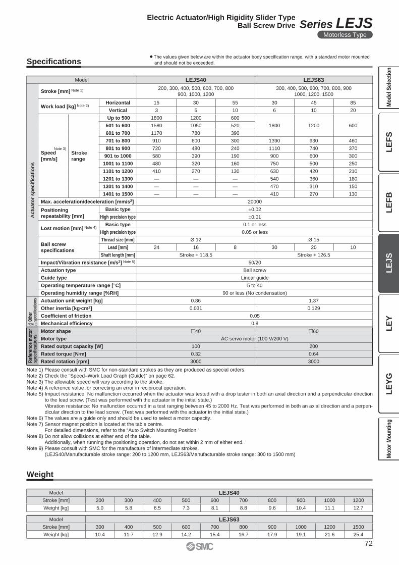
Specifi cations
Weight
Note 1) Please consult with SMC for non-standard strokes as they are produced as special orders.
Note 2) Check the “Speed–Work Load Graph (Guide)” on page 62.
Note 3) The allowable speed will vary according to the stroke.
Note 4) A reference value for correcting an error in reciprocal operation.
Note 5) Impact resistance: No malfunction occurred when the actuator was tested with a drop tester in both an axial direction and a perpendicular direction
to the lead screw. (Test was performed with the actuator in the initial state.)
Vibration resistance: No malfunction occurred in a test ranging between 45 to 2000 Hz. Test was performed in both an axial direction and a perpen-
dicular direction to the lead screw. (Test was performed with the actuator in the initial state.)
Note 6) The values are a guide only and should be used to select a motor capacity.
Note 7) Sensor magnet position is located at the table centre.
For detailed dimensions, refer to the “Auto Switch Mounting Position.”
Note 8) Do not allow collisions at either end of the table.
Additionally, when running the positioning operation, do not set within 2 mm of either end.
Note 9) Please consult with SMC for the manufacture of intermediate strokes.
(LEJS40/Manufacturable stroke range: 200 to 1200 mm, LEJS63/Manufacturable stroke range: 300 to 1500 mm)
¡The values given below are within the actuator body specifi cation range, with a standard motor mounted
and should not be exceeded.
Model LEJS40 LEJS63
Actu
ato
r sp
ecifi
cati
on
s
Stroke [mm] Note 1) 200, 300, 400, 500, 600, 700, 800
900, 1000, 1200
300, 400, 500, 600, 700, 800, 900
1000, 1200, 1500
Work load [kg] Note 2)Horizontal 15 30 55 30 45 85
Vertical 3 5 10 6 10 20
Note 3)
Speed
[mm/s]
Stroke
range
Up to 500 1800 1200 600
1800 1200 600501 to 600 1580 1050 520
601 to 700 1170 780 390
701 to 800 910 600 300 1390 930 460
801 to 900 720 480 240 1110 740 370
901 to 1000 580 390 190 900 600 300
1001 to 1100 480 320 160 750 500 250
1101 to 1200 410 270 130 630 420 210
1201 to 1300 — — — 540 360 180
1301 to 1400 — — — 470 310 150
1401 to 1500 — — — 410 270 130
Max. acceleration/deceleration [mm/s2] 20000
Positioning
repeatability [mm]
Basic type ±0.02
High precision type ±0.01
Lost motion [mm] Note 4)Basic type 0.1 or less
High precision type 0.05 or less
Ball screw
specifi cations
Thread size [mm] Ø 12 Ø 15
Lead [mm] 24 16 8 30 20 10
Shaft length [mm] Stroke + 118.5 Stroke + 126.5
Impact/Vibration resistance [m/s2] Note 5) 50/20
Actuation type Ball screw
Guide type Linear guide
Operating temperature range [°C] 5 to 40
Operating humidity range [%RH] 90 or less (No condensation)
Oth
er
spec
ifi ca
tions Actuation unit weight [kg] 0.86 1.37
Other inertia [kg·cm2] 0.031 0.129
Coeffi cient of friction 0.05
Mechanical effi ciency 0.8
Refe
ren
ce m
oto
rsp
ecifi
cati
on
s
Motor shape �40 �60
Motor type AC servo motor (100 V/200 V)
Rated output capacity [W] 100 200
Rated torque [N·m] 0.32 0.64
Rated rotation [rpm] 3000 3000
Model LEJS40
Stroke [mm] 200 300 400 500 600 700 800 900 1000 1200
Weight [kg] 5.0 5.8 6.5 7.3 8.1 8.8 9.6 10.4 11.1 12.7
Model LEJS63
Stroke [mm] 300 400 500 600 700 800 900 1000 1200 1500
Weight [kg] 10.4 11.7 12.9 14.2 15.4 16.7 17.9 19.1 21.6 25.4
Note 6)
72
Electric Actuator/High Rigidity Slider TypeBall Screw Drive Series LEJS
Motorless Type
LE
FS
LE
FB
LE
JS
LE
YL
EY
GM
od
el
Se
lec
tio
nM
oto
r M
ou
nti
ng
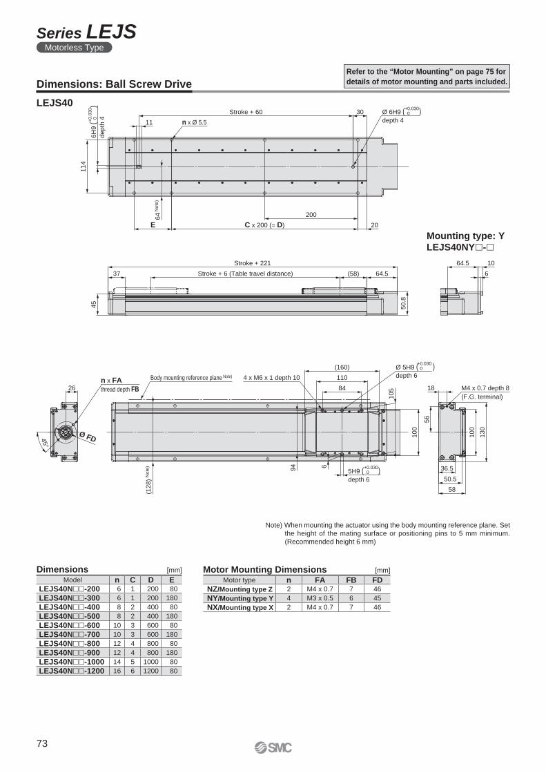
56
36.5
50.5
58130
100
18n x FA
thread depth FB26
100
45°
Ø FD
(160)
110
84
94 6
105
45
(58) 64.537
50.8
114
30
11
20
200
E
64.5 10
6
(128)
No
te)
Stroke + 6 (Table travel distance)
Stroke + 221
M4 x 0.7 depth 8
(F.G. terminal)
4 x M6 x 1 depth 10
Ø 5H9 ( )depth 6
+0.030 0
Body mounting reference plane Note)
Ø 6H9 ( )depth 4
+0.030 0Stroke + 60
n x Ø 5.5
64
No
te)
C x 200 (= D)
6H
9 (
)
depth
4+0
.03
0
0
5H9 ( )depth 6
+0.030 0
Refer to the “Motor Mounting” on page 75 for
details of motor mounting and parts included.Dimensions: Ball Screw Drive
LEJS40
Motor Mounting Dimensions [mm]Dimensions [mm]
Note) When mounting the actuator using the body mounting reference plane. Set
the height of the mating surface or positioning pins to 5 mm minimum.
(Recommended height 6 mm)
Model n C D ELEJS40N��-200 6 1 200 80
LEJS40N��-300 6 1 200 180
LEJS40N��-400 8 2 400 80
LEJS40N��-500 8 2 400 180
LEJS40N��-600 10 3 600 80
LEJS40N��-700 10 3 600 180
LEJS40N��-800 12 4 800 80
LEJS40N��-900 12 4 800 180
LEJS40N��-1000 14 5 1000 80
LEJS40N��-1200 16 6 1200 80
Motor type n FA FB FDNZ/Mounting type Z 2 M4 x 0.7 7 46
NY/Mounting type Y 4 M3 x 0.5 6 45
NX/Mounting type X 2 M4 x 0.7 7 46
Mounting type: YLEJS40NY�-�
73
Series LEJSMotorless Type
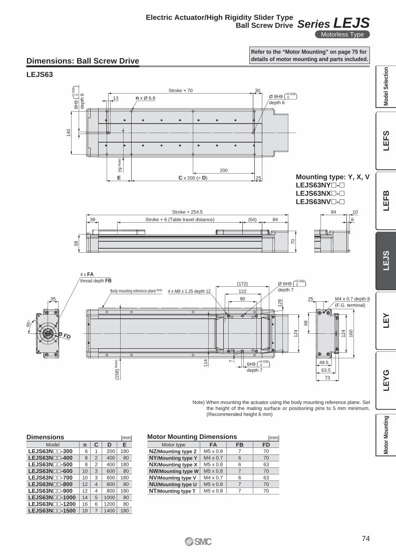
25
45
°
Ø FD 160
124
68
49.5
63.5
73
(172)
122
90124
35
129
114 7
(64) 8439
70
58
84 10
6
140
13
30
200
E 25
n x Ø 6.8
Stroke + 70
C x 200 (= D)
79
Note
)
Ø 8H9 ( )depth 6
+0.036 0
8H
9 (
)
depth
6+0.0
36
0
Stroke + 254.5
M4 x 0.7 depth 8
(F.G. terminal)
Stroke + 6 (Table travel distance)
Body mounting reference plane Note) 4 x M8 x 1.25 depth 12
(158)
Note
)
Ø 6H9 ( )depth 7
+0.030 0
6H9 ( )depth 7
+0.030 0
4 x FA
thread depth FB
Dimensions: Ball Screw Drive
LEJS63
Refer to the “Motor Mounting” on page 75 for
details of motor mounting and parts included.
Mounting type: Y, X, VLEJS63NY�-�LEJS63NX�-�LEJS63NV�-�
Dimensions [mm]
Note) When mounting the actuator using the body mounting reference plane. Set
the height of the mating surface or positioning pins to 5 mm minimum.
(Recommended height 6 mm)
Motor Mounting Dimensions [mm]
Motor type FA FB FDNZ/Mounting type Z M5 x 0.8 7 70
NY/Mounting type Y M4 x 0.7 6 70
NX/Mounting type X M5 x 0.8 6 63
NW/Mounting type W M5 x 0.8 7 70
NV/Mounting type V M4 x 0.7 6 63
NU/Mounting type U M5 x 0.8 7 70
NT/Mounting type T M5 x 0.8 7 70
Model n C D ELEJS63N��-300 6 1 200 180
LEJS63N��-400 8 2 400 80
LEJS63N��-500 8 2 400 180
LEJS63N��-600 10 3 600 80
LEJS63N��-700 10 3 600 180
LEJS63N��-800 12 4 800 80
LEJS63N��-900 12 4 800 180
LEJS63N��-1000 14 5 1000 80
LEJS63N��-1200 16 6 1200 80
LEJS63N��-1500 18 7 1400 180
74
Electric Actuator/High Rigidity Slider TypeBall Screw Drive Series LEJS
Motorless Type
LE
FS
LE
FB
LE
JS
LE
YL
EY
GM
od
el
Se
lec
tio
nM
oto
r M
ou
nti
ng
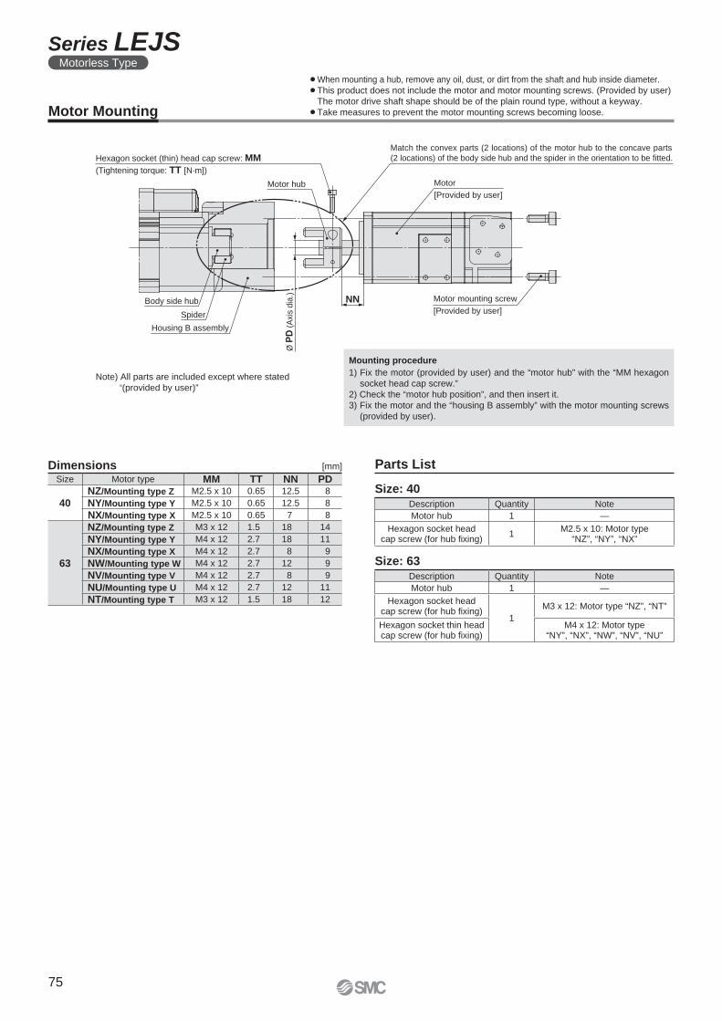
NN
Hexagon socket (thin) head cap screw: MM
(Tightening torque: TT [N·m])
Motor hub
Body side hub
Spider
Motor
[Provided by user]
Housing B assembly
Ø P
D (
Axi
s dia
.)Motor mounting screw
[Provided by user]
Match the convex parts (2 locations) of the motor hub to the concave parts
(2 locations) of the body side hub and the spider in the orientation to be fitted.
Note) All parts are included except where stated
“(provided by user)”
Motor Mounting
Dimensions [mm]
Size: 40
Size: 63
Parts List
Mounting procedure
1) Fix the motor (provided by user) and the “motor hub” with the “MM hexagon
socket head cap screw.”
2) Check the “motor hub position”, and then insert it.
3) Fix the motor and the “housing B assembly” with the motor mounting screws
(provided by user).
Description Quantity Note
Motor hub 1 —
Hexagon socket headcap screw (for hub fi xing)
1
M3 x 12: Motor type “NZ”, “NT”
Hexagon socket thin headcap screw (for hub fi xing)
M4 x 12: Motor type“NY”, “NX”, “NW”, “NV”, “NU”
Size Motor type MM TT NN PD
40NZ/Mounting type Z M2.5 x 10 0.65 12.5 8
NY/Mounting type Y M2.5 x 10 0.65 12.5 8
NX/Mounting type X M2.5 x 10 0.65 7 8
63
NZ/Mounting type Z M3 x 12 1.5 18 14
NY/Mounting type Y M4 x 12 2.7 18 11
NX/Mounting type X M4 x 12 2.7 8 9
NW/Mounting type W M4 x 12 2.7 12 9
NV/Mounting type V M4 x 12 2.7 8 9
NU/Mounting type U M4 x 12 2.7 12 11
NT/Mounting type T M3 x 12 1.5 18 12
Description Quantity Note
Motor hub 1 —
Hexagon socket headcap screw (for hub fi xing)
1M2.5 x 10: Motor type
“NZ”, “NY”, “NX”
¡When mounting a hub, remove any oil, dust, or dirt from the shaft and hub inside diameter.
¡This product does not include the motor and motor mounting screws. (Provided by user)
The motor drive shaft shape should be of the plain round type, without a keyway.
¡Take measures to prevent the motor mounting screws becoming loose.
75
Series LEJSMotorless Type
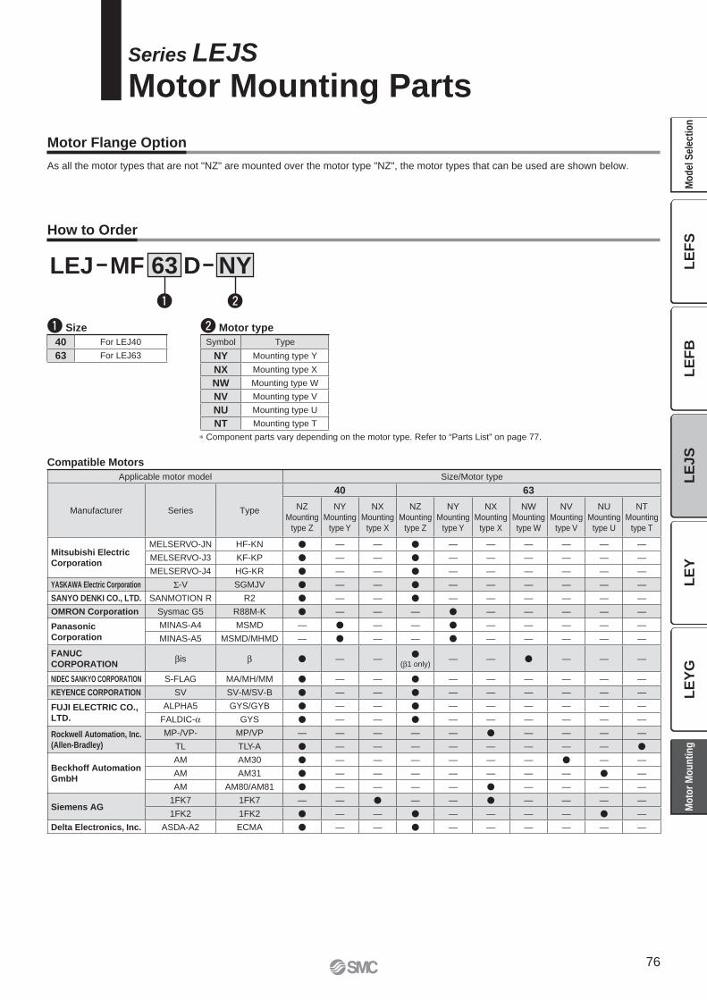
Series LEJS
Motor Mounting Parts
q Size
∗ Component parts vary depending on the motor type. Refer to “Parts List” on page 77.
w Motor type
40 For LEJ40
63 For LEJ63
Symbol Type
NY Mounting type Y
NX Mounting type X
NW Mounting type W
NV Mounting type V
NU Mounting type U
NT Mounting type T
Compatible Motors
Applicable motor model Size/Motor type
Manufacturer Series Type
40 63
NZ
Mounting
type Z
NY
Mounting
type Y
NX
Mounting
type X
NZ
Mounting
type Z
NY
Mounting
type Y
NX
Mounting
type X
NW
Mounting
type W
NV
Mounting
type V
NU
Mounting
type U
NT
Mounting
type T
Mitsubishi Electric
Corporation
MELSERVO-JN HF-KN � — — � — — — — — —
MELSERVO-J3 KF-KP � — — � — — — — — —
MELSERVO-J4 HG-KR � — — � — — — — — —
YASKAWA Electric Corporation Σ-V SGMJV � — — � — — — — — —
SANYO DENKI CO., LTD. SANMOTION R R2 � — — � — — — — — —
OMRON Corporation Sysmac G5 R88M-K � — — — � — — — — —
Panasonic
Corporation
MINAS-A4 MSMD — � — — � — — — — —
MINAS-A5 MSMD/MHMD — � — — � — — — — —
FANUC
CORPORATIONβis β � — —
�(β1 only)
— — � — — —
NIDEC SANKYO CORPORATION S-FLAG MA/MH/MM � — — � — — — — — —
KEYENCE CORPORATION SV SV-M/SV-B � — — � — — — — — —
FUJI ELECTRIC CO.,
LTD.
ALPHA5 GYS/GYB � — — � — — — — — —
FALDIC-α GYS � — — � — — — — — —
Rockwell Automation, Inc.
(Allen-Bradley)
MP-/VP- MP/VP — — — — — � — — — —
TL TLY-A � — — — — — — — — �
Beckhoff Automation
GmbH
AM AM30 � — — — — — — � — —
AM AM31 � — — — — — — — � —
AM AM80/AM81 � — — — — � — — — —
Siemens AG1FK7 1FK7 — — � — — � — — — —
1FK2 1FK2 � — — � — — — — � —
Delta Electronics, Inc. ASDA-A2 ECMA � — — � — — — — — —
LEJ MF D NY63
q w
Motor Flange Option
As all the motor types that are not "NZ" are mounted over the motor type "NZ", the motor types that can be used are shown below.
How to Order
76
LE
YL
EY
GL
EF
SL
EF
BL
EJS
Mo
de
l S
ele
cti
on
Mo
tor
Mo
un
tin
g
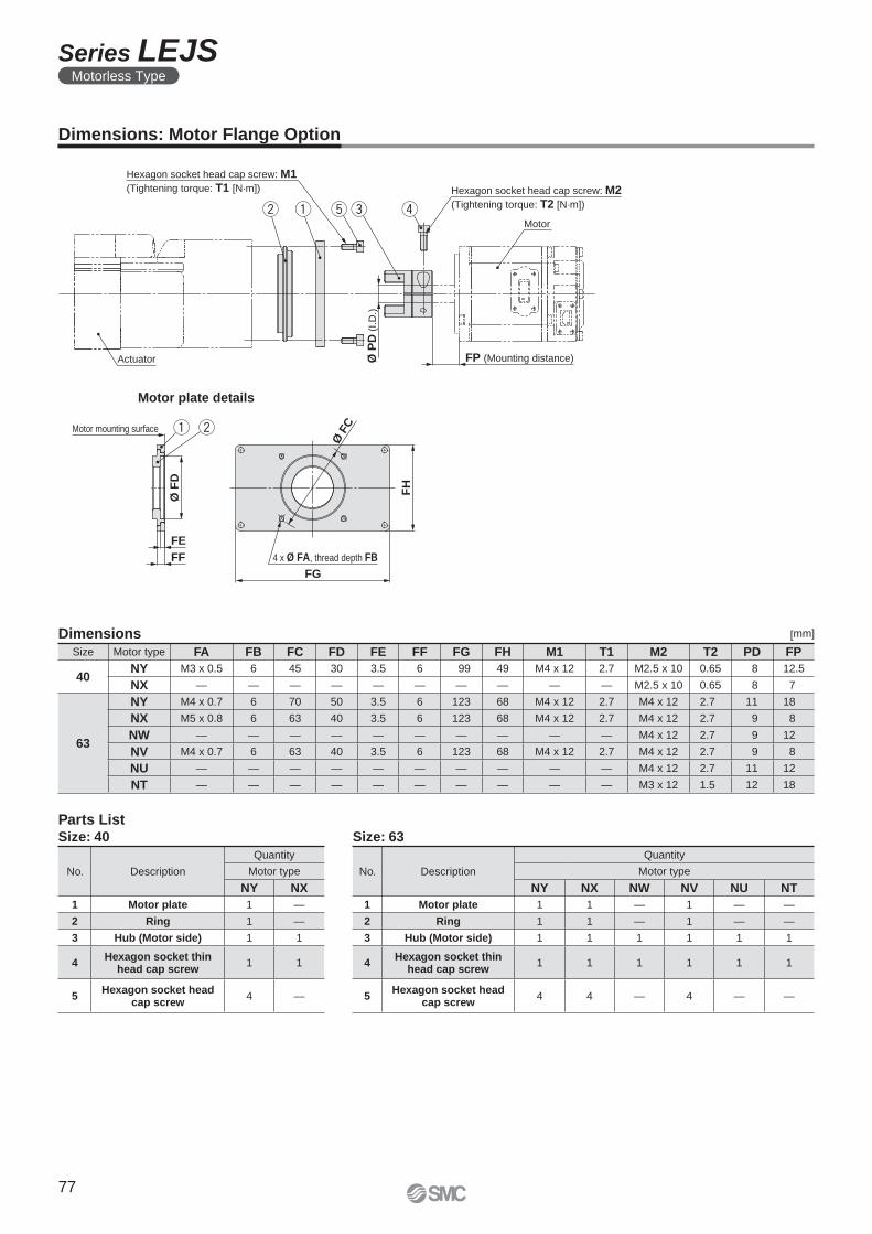
Actuator
Hexagon socket head cap screw: M1
(Tightening torque: T1 [N·m])
FP (Mounting distance)Ø P
D (
I.D
.)
Hexagon socket head cap screw: M2
(Tightening torque: T2 [N·m])t reMotor
FG
4 x Ø FA, thread depth FB
Ø F
C
FH
qw
Motor mounting surface
Ø F
D
FF
FE
q w
Dimensions: Motor Flange Option
Motor plate details
Parts ListSize: 40
No. Description
Quantity
Motor type
NY NX
1 Motor plate 1 —
2 Ring 1 —
3 Hub (Motor side) 1 1
4Hexagon socket thin
head cap screw1 1
5Hexagon socket head
cap screw4 —
Size: 63
No. Description
Quantity
Motor type
NY NX NW NV NU NT
1 Motor plate 1 1 — 1 — —
2 Ring 1 1 — 1 — —
3 Hub (Motor side) 1 1 1 1 1 1
4Hexagon socket thin
head cap screw1 1 1 1 1 1
5Hexagon socket head
cap screw4 4 — 4 — —
Dimensions [mm]
Size Motor type FA FB FC FD FE FF FG FH M1 T1 M2 T2 PD FP
40NY M3 x 0.5 6 45 30 3.5 6 99 49 M4 x 12 2.7 M2.5 x 10 0.65 8 12.5
NX — — — — — — — — — — M2.5 x 10 0.65 8 7
63
NY M4 x 0.7 6 70 50 3.5 6 123 68 M4 x 12 2.7 M4 x 12 2.7 11 18
NX M5 x 0.8 6 63 40 3.5 6 123 68 M4 x 12 2.7 M4 x 12 2.7 9 8
NW — — — — — — — — — — M4 x 12 2.7 9 12
NV M4 x 0.7 6 63 40 3.5 6 123 68 M4 x 12 2.7 M4 x 12 2.7 9 8
NU — — — — — — — — — — M4 x 12 2.7 11 12
NT — — — — — — — — — — M3 x 12 1.5 12 18
77
Series LEJSMotorless Type
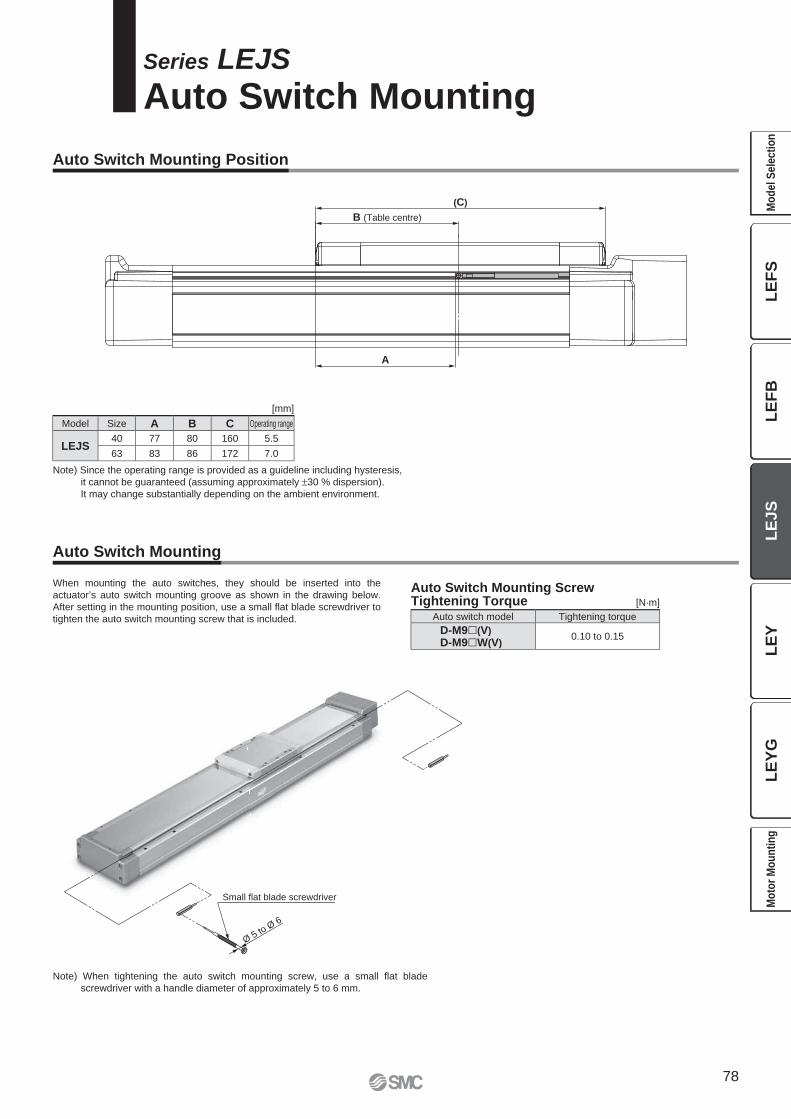
Ø 5 to Ø
6
Small flat blade screwdriver
(C)
B (Table centre)
A
Series LEJS
Auto Switch Mounting
Auto Switch Mounting Position
Auto Switch Mounting
Auto Switch Mounting ScrewTightening Torque [N·m]
When mounting the auto switches, they should be inserted into the
actuator’s auto switch mounting groove as shown in the drawing below.
After setting in the mounting position, use a small fl at blade screwdriver to
tighten the auto switch mounting screw that is included.
Note) When tightening the auto switch mounting screw, use a small fl at blade
screwdriver with a handle diameter of approximately 5 to 6 mm.
Note) Since the operating range is provided as a guideline including hysteresis,
it cannot be guaranteed (assuming approximately ±30 % dispersion).
It may change substantially depending on the ambient environment.
[mm]
Model Size A B C Operating range
LEJS40 77 80 160 5.5
63 83 86 172 7.0
Auto switch model Tightening torque
D-M9�(V)
D-M9�W(V)0.10 to 0.15
78
LE
FS
LE
FB
LE
JS
LE
YL
EY
GM
od
el
Se
lec
tio
nM
oto
r M
ou
nti
ng
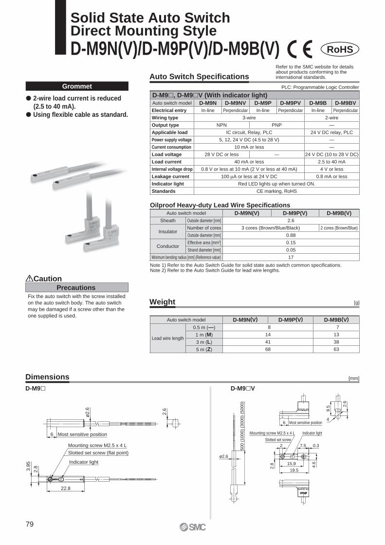
Most sensitive position
ø2.6
2.6
3.9
5
2.8
6
22.8
Mounting screw M2.5 x 4 L
Slotted set screw (flat point)
Indicator light
19.5
15.9
7.5
9.5
4
2.6
0.3
ø2.6
Indicator light
Slotted set screw
2
Most sensitive position6
2.8 4.6
50
0 (
10
00
) (3
00
0)
(50
00
)
Mounting screw M2.5 x 4 L
Auto Switch Specifi cations
Weight
Dimensions
Precautions
Caution
Fix the auto switch with the screw installed
on the auto switch body. The auto switch
may be damaged if a screw other than the
one supplied is used.
[g]
Grommet
Note 1) Refer to the Auto Switch Guide for solid state auto switch common specifi cations.Note 2) Refer to the Auto Switch Guide for lead wire lengths.
D-M9� D-M9�V
� 2-wire load current is reduced
(2.5 to 40 mA).
� Using fl exible cable as standard.
[mm]
Oilproof Heavy-duty Lead Wire Specifi cations
RoHS
Solid State Auto SwitchDirect Mounting Style
D-M9N(V)/D-M9P(V)/D-M9B(V)
PLC: Programmable Logic Controller
Refer to the SMC website for details about products conforming to the international standards.
D-M9�, D-M9�V (With indicator light)Auto switch model D-M9N D-M9NV D-M9P D-M9PV D-M9B D-M9BV
Electrical entry In-line Perpendicular In-line Perpendicular In-line Perpendicular
Wiring type 3-wire 2-wire
Output type NPN PNP —
Applicable load IC circuit, Relay, PLC 24 V DC relay, PLC
Power supply voltage 5, 12, 24 V DC (4.5 to 28 V) —
Current consumption 10 mA or less —
Load voltage 28 V DC or less — 24 V DC (10 to 28 V DC)
Load current 40 mA or less 2.5 to 40 mA
Internal voltage drop 0.8 V or less at 10 mA (2 V or less at 40 mA) 4 V or less
Leakage current 100 μA or less at 24 V DC 0.8 mA or less
Indicator light Red LED lights up when turned ON.
Standards CE marking, RoHS
Auto switch model D-M9N(V) D-M9P(V) D-M9B(V)
Lead wire length
0.5 m (—) 8 7
1 m (M) 14 13
3 m (L) 41 38
5 m (Z) 68 63
Auto switch model D-M9N(V) D-M9P(V) D-M9B(V)
Sheath Outside diameter [mm] 2.6
InsulatorNumber of cores 3 cores (Brown/Blue/Black) 2 cores (Brown/Blue)
Outside diameter [mm] 0.88
ConductorEffective area [mm2] 0.15
Strand diameter [mm] 0.05
Minimum bending radius [mm] (Reference value) 17
79
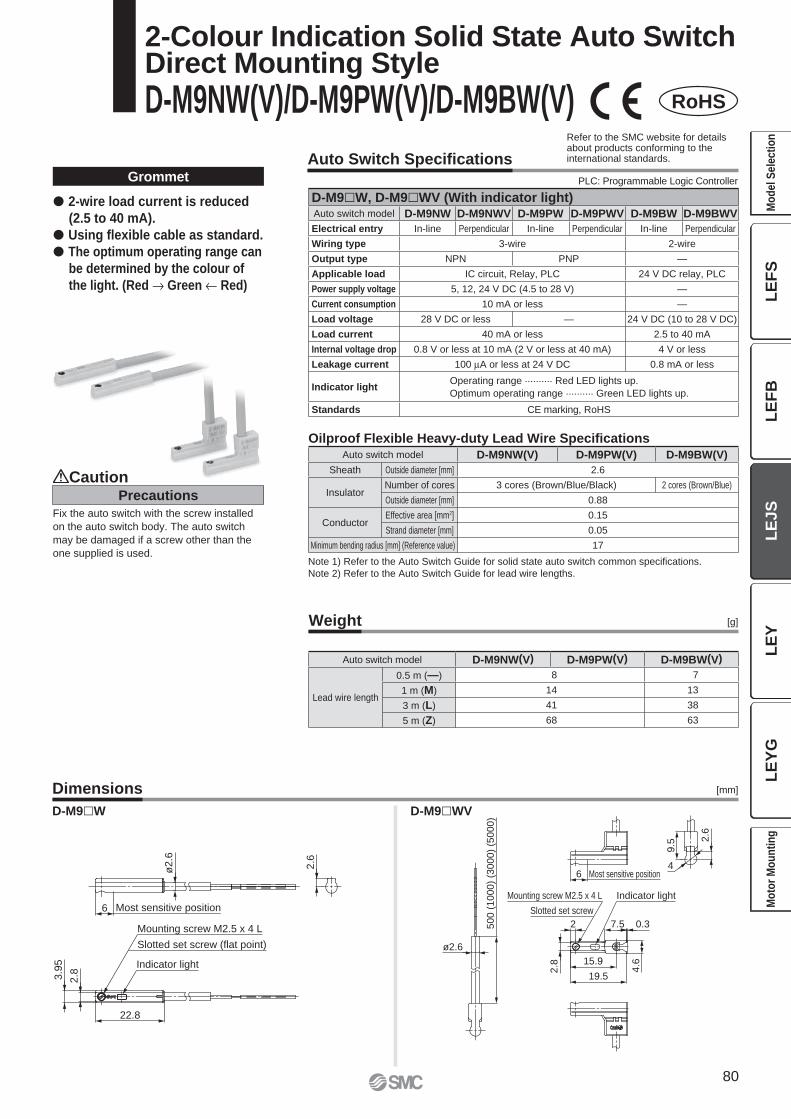
6 Most sensitive position
2.6
ø2.6
22.8
Indicator light
3.9
5
2.8
Slotted set screw (flat point)
Mounting screw M2.5 x 4 L 500 (
1000)
(3000)
(5000)
Indicator light
ø2.6
4.6
0.37.5
Mounting screw M2.5 x 4 L
Slotted set screw
2.8
9.5
2.6
4Most sensitive position6
19.5
15.9
2
Auto Switch Specifi cations
Weight
Dimensions
[g]
[mm]
Grommet
Note 1) Refer to the Auto Switch Guide for solid state auto switch common specifi cations.
Note 2) Refer to the Auto Switch Guide for lead wire lengths.
� 2-wire load current is reduced
(2.5 to 40 mA).
� Using fl exible cable as standard.
� The optimum operating range can
be determined by the colour of
the light. (Red → Green ← Red)
D-M9�W D-M9�WV
RoHS
Oilproof Flexible Heavy-duty Lead Wire Specifi cations
2-Colour Indication Solid State Auto SwitchDirect Mounting Style
D-M9NW(V)/D-M9PW(V)/D-M9BW(V)
Precautions
Caution
Fix the auto switch with the screw installed
on the auto switch body. The auto switch
may be damaged if a screw other than the
one supplied is used.
Refer to the SMC website for details about products conforming to the international standards.
PLC: Programmable Logic Controller
D-M9�W, D-M9�WV (With indicator light)Auto switch model D-M9NW D-M9NWV D-M9PW D-M9PWV D-M9BW D-M9BWV
Electrical entry In-line Perpendicular In-line Perpendicular In-line Perpendicular
Wiring type 3-wire 2-wire
Output type NPN PNP —
Applicable load IC circuit, Relay, PLC 24 V DC relay, PLC
Power supply voltage 5, 12, 24 V DC (4.5 to 28 V) —
Current consumption 10 mA or less —
Load voltage 28 V DC or less — 24 V DC (10 to 28 V DC)
Load current 40 mA or less 2.5 to 40 mA
Internal voltage drop 0.8 V or less at 10 mA (2 V or less at 40 mA) 4 V or less
Leakage current 100 μA or less at 24 V DC 0.8 mA or less
Indicator lightOperating range .......... Red LED lights up.
Optimum operating range .......... Green LED lights up.
Standards CE marking, RoHS
Auto switch model D-M9NW(V) D-M9PW(V) D-M9BW(V)
Sheath Outside diameter [mm] 2.6
InsulatorNumber of cores 3 cores (Brown/Blue/Black) 2 cores (Brown/Blue)
Outside diameter [mm] 0.88
ConductorEffective area [mm2] 0.15
Strand diameter [mm] 0.05
Minimum bending radius [mm] (Reference value) 17
Auto switch model D-M9NW(V) D-M9PW(V) D-M9BW(V)
Lead wire length
0.5 m (—) 8 7
1 m (M) 14 13
3 m (L) 41 38
5 m (Z) 68 63
80
LE
FS
LE
FB
LE
JS
LE
YL
EY
GM
od
el
Se
lec
tio
nM
oto
r M
ou
nti
ng
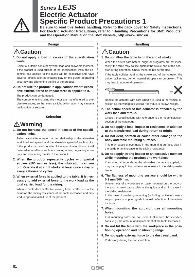
Design Handling
Caution Caution1. Do not apply a load in excess of the specifi cation
limits.
Select a suitable actuator by work load and allowable moment.
If the product is used outside of the specifi cation limits, the ec-
centric load applied to the guide will be excessive and have
adverse effects such as creating play on the guide, degrading
accuracy and shortening the life of the product.
2. Do not use the product in applications where exces-
sive external force or impact force is applied to it.
The product can be damaged.
The components including the motor are manufactured to pre-
cise tolerances, so that even a slight deformation may cause a
malfunction or seizure.
Warning
Selection
1. Do not increase the speed in excess of the specifi -
cation limits.
Select a suitable actuator by the relationship of the allowable
work load and speed, and the allowable speed of each stroke.
If the product is used outside of the specifi cation limits, it will
have adverse effects such as creating noise, degrading accu-
racy and shortening the life of the product.
2. When the product repeatedly cycles with partial
strokes (100 mm or less), the lubrication can run
out. Operate it at a full stroke at least once a day or
ev ery a thousand cycles.
3. When external force is applied to the table, it is nec-
essary to add external force to the work load as the
total carried load for the sizing.
When a cable duct or fl exible moving tube is attached to the
actuator, the sliding resistance of the table increases and may
lead to operational failure of the product.
1. Do not allow the table to hit the end of stroke.
When the driver parameters, origin or programs are set incor-
rectly, the table may collide against the stroke end of the actu-
ator during operation. Check these points before use.
If the table collides against the stroke end of the actuator, the
guide, ball screw, belt or internal stopper can be broken. This
may lead to abnormal operation.
Handle the actuator with care when it is used in the vertical di-
rection as the workpiece will fall freely due to its own weight.
2. The actual speed of this actuator is affected by the
work load and stroke.
Check the specifi cations with reference to the model selection
section of the catalogue.
3. Do not apply a load, impact or resistance in addition
to the transferred load during return to origin.
4. Do not dent, scratch or cause other damage to the
body and table mounting surfaces.
This may cause unevenness in the mounting surface, play in
the guide or an increase in the sliding resistance.
5. Do not apply strong impact or an excessive moment
while mounting the product or a workpiece.
If an external force above the allowable moment is applied, it
may cause play in the guide or an increase in the sliding resis-
tance.
6. The fl atness of mounting surface should be within
0.1 mm/500 mm.
Unevenness of a workpiece or base mounted on the body of
the product may cause play in the guide and an increase in
the sliding resistance.
In the case of overhang mounting (including cantilever), use a
support plate or support guide to avoid defl ection of the actua-
tor body.
7. When mounting the actuator, use all mounting
holes.
If all mounting holes are not used, it infl uences the specifi ca-
tions, e.g., the amount of displacement of the table increases.
8. Do not hit the table with the workpiece in the posi-
tioning operation and positioning range.
9. Do not apply external force to the dust seal band.
Particularly during the transportation
Series LEJSElectric ActuatorSpecifi c Product Precautions 1Be sure to read this before handling. Refer to the back cover for Safety Instructions. For Electric Actuator Precautions, refer to “Handling Precautions for SMC Products” and the Operation Manual on the SMC website, http://www.smc.eu
81
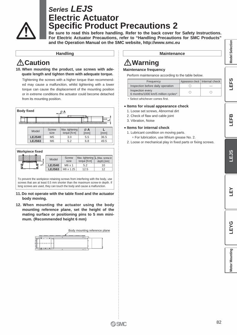
Ø AL
L
Body mounting reference plane
To prevent the workpiece retaining screws from interfering with the body, use
screws that are at least 0.5 mm shorter than the maximum screw-in depth. If
long screws are used, they can touch the body and cause a malfunction.
Workpiece fi xed
Body fi xed
Handling Maintenance
CautionMaintenance frequency
Perform maintenance according to the table below.
∗ Select whichever comes fi rst.
Warning10. When mounting the product, use screws with ade-
quate length and tighten them with adequate torque.
Tightening the screws with a higher torque than recommend-
ed may cause a malfunction, whilst tightening with a lower
torque can cause the displacement of the mounting position
or in extreme conditions the actuator could become detached
from its mounting position.
11. Do not operate with the table fi xed and the actuator
body moving.
12. When mounting the actuator using the body
mounting reference plane, set the height of the
mating surface or positioning pins to 5 mm mini-
mum. (Recommended height 6 mm)
• Items for visual appearance check
1. Loose set screws, Abnormal dirt
2. Check of fl aw and cable joint
3. Vibration, Noise
• Items for internal check
1. Lubricant condition on moving parts.
∗ For lubrication, use lithium grease No. 2.
2. Loose or mechanical play in fi xed parts or fi xing screws.
Series LEJSElectric ActuatorSpecifi c Product Precautions 2Be sure to read this before handling. Refer to the back cover for Safety Instructions. For Electric Actuator Precautions, refer to “Handling Precautions for SMC Products” and the Operation Manual on the SMC website, http://www.smc.eu
ModelScrewsize
Max. tighteningtorque [N·m]
Ø A[mm]
L[mm]
LEJS40 M5 3.0 5.5 36.5
LEJS63 M6 5.2 6.8 49.5
ModelScrewsize
Max. tighteningtorque [N·m]
L (Max. screw-indepth) [mm]
LEJS40 M6 x 1 5.2 10
LEJS63 M8 x 1.25 12.5 12
Frequency Appearance check Internal check
Inspection before daily operation � —
Inspection every6 months/1000 km/5 million cycles∗ � �
82
LE
FS
LE
FB
LE
JS
LE
YL
EY
GM
od
el
Se
lec
tio
nM
oto
r M
ou
nti
ng

83
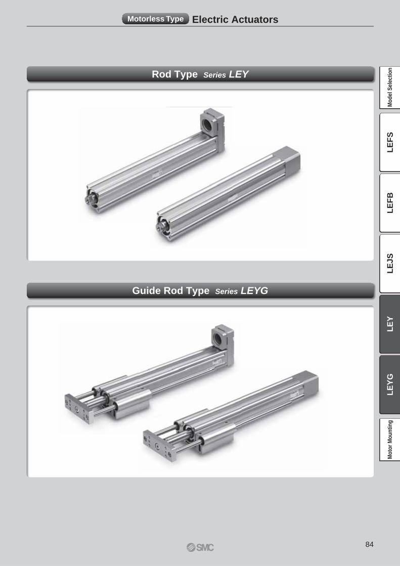
Motorless Type Electric Actuators
Rod Type Series LEY
Guide Rod Type Series LEYG
84
LE
FS
LE
FB
LE
JS
LE
YL
EY
GM
od
el
Se
lec
tio
nM
oto
r M
ou
nti
ng
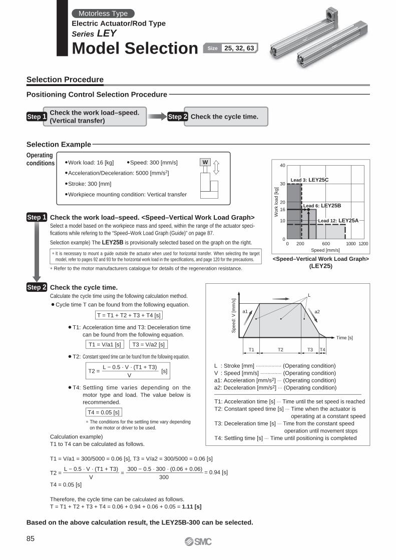
0
10
16
20
30
40
0 200 600 1000 1200
Speed [mm/s]
Wo
rk lo
ad
[kg
]
Lead 12: LEY25A
Lead 6: LEY25B
Lead 3: LEY25C
T1
a1 a2
L
Speed:
V [
mm
/s]
Time [s]
T2 T3 T4
W
Check the work load–speed. <Speed–Vertical Work Load Graph>
Check the cycle time.
�Work load: 16 [kg] �Speed: 300 [mm/s]
�Acceleration/Deceleration: 5000 [mm/s2]
�Stroke: 300 [mm]
�Workpiece mounting condition: Vertical transfer
Calculate the cycle time using the following calculation method.
¡Cycle time T can be found from the following equation.
Select a model based on the workpiece mass and speed, within the range of the actuator speci-
fi cations while refering to the “Speed–Work Load Graph (Guide)” on page 87.
Selection example) The LEY25B is provisionally selected based on the graph on the right.
T4 = 0.05 [s]
¡T4: Settling time varies depending on the
motor type and load. The value below is
recommended.
¡T2: Constant speed time can be found from the following equation.
¡T1: Acceleration time and T3: Deceleration time
can be found from the following equation.
∗ It is necessary to mount a guide outside the actuator when used for horizontal transfer. When selecting the target
model, refer to pages 92 and 93 for the horizontal work load in the specifi cations, and page 120 for the precautions.
∗ Refer to the motor manufacturers catalogue for details of the regeneration resistance.
∗ The conditions for the settling time vary depending
on the motor or driver to be used.
<Speed–Vertical Work Load Graph>
(LEY25)
Step 1
Step 2
Operating
conditions
Selection Procedure
Positioning Control Selection Procedure
Selection Example
Step 1Check the work load–speed.
(Vertical transfer)Step 2 Check the cycle time.
T = T1 + T2 + T3 + T4 [s]
T1 = V/a1 [s] T3 = V/a2 [s]
T2 = [s]L − 0.5 · V · (T1 + T3)
V
L : Stroke [mm] ⋅⋅⋅⋅⋅⋅⋅⋅⋅⋅⋅⋅⋅⋅⋅⋅⋅⋅ (Operating condition)
V : Speed [mm/s] ⋅⋅⋅⋅⋅⋅⋅⋅⋅⋅⋅⋅⋅⋅⋅ (Operating condition)
a1: Acceleration [mm/s2] ⋅⋅⋅ (Operating condition)
a2: Deceleration [mm/s2] ⋅⋅⋅ (Operating condition)
T1: Acceleration time [s] ⋅⋅⋅ Time until the set speed is reached
T2: Constant speed time [s] ⋅⋅⋅ Time when the actuator is
operating at a constant speed
T3: Deceleration time [s] ⋅⋅⋅ Time from the constant speed
operation until movement stops
T4: Settling time [s] ⋅⋅⋅ Time until positioning is completedCalculation example)
T1 to T4 can be calculated as follows.
T1 = V/a1 = 300/5000 = 0.06 [s], T3 = V/a2 = 300/5000 = 0.06 [s]
T4 = 0.05 [s]
Therefore, the cycle time can be calculated as follows.
T = T1 + T2 + T3 + T4 = 0.06 + 0.94 + 0.06 + 0.05 = 1.11 [s]
T2 = = = 0.94 [s]L − 0.5 · V · (T1 + T3)
V
300 − 0.5 · 300 · (0.06 + 0.06)
300
Based on the above calculation result, the LEY25B-300 can be selected.
Motorless Type
Electric Actuator/Rod Type
Series LEY
Model Selection 25, 32, 63Size
85
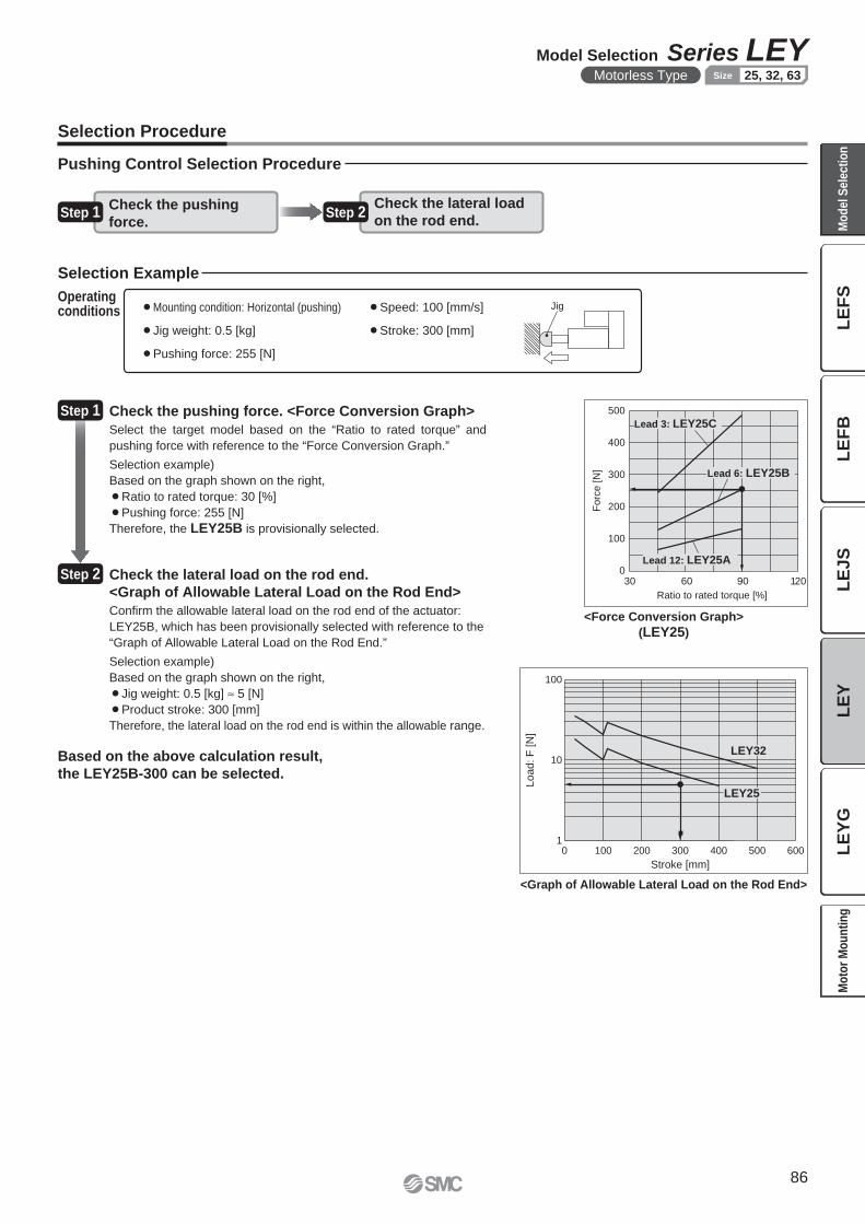
Jig
Lo
ad
: F
[N
]
Stroke [mm]
0 100 200 300 400 500 600
100
10
1
LEY32
LEY25
Forc
e [
N]
Ratio to rated torque [%]
500
400
300
200
100
06030 12090
Lead 12: LEY25A
Lead 3: LEY25C
Lead 6: LEY25B
<Force Conversion Graph>
(LEY25)
<Graph of Allowable Lateral Load on the Rod End>
Step 1 Check the pushing force. <Force Conversion Graph>
¡Mounting condition: Horizontal (pushing) ¡Speed: 100 [mm/s]
¡Jig weight: 0.5 [kg] ¡Stroke: 300 [mm]
¡Pushing force: 255 [N]
Operatingconditions
Pushing Control Selection Procedure
Selection Example
Check the lateral load
on the rod end.Step 1
Check the pushing
force.
Select the target model based on the “Ratio to rated torque” and
pushing force with reference to the “Force Conversion Graph.”
Selection example)
Based on the graph shown on the right,
¡Ratio to rated torque: 30 [%]
¡Pushing force: 255 [N]
Therefore, the LEY25B is provisionally selected.
Step 2 Check the lateral load on the rod end.
<Graph of Allowable Lateral Load on the Rod End>
Confi rm the allowable lateral load on the rod end of the actuator:
LEY25B, which has been provisionally selected with reference to the
“Graph of Allowable Lateral Load on the Rod End.”
Selection example)
Based on the graph shown on the right,
¡Jig weight: 0.5 [kg] ≈ 5 [N]
¡Product stroke: 300 [mm]
Therefore, the lateral load on the rod end is within the allowable range.
Step 2
Based on the above calculation result,
the LEY25B-300 can be selected.
Selection Procedure
86
Model Selection Series LEYMotorless Type 25, 32, 63Size
LE
FS
LE
FB
LE
JS
LE
YL
EY
GM
od
el
Se
lec
tio
nM
oto
r M
ou
nti
ng
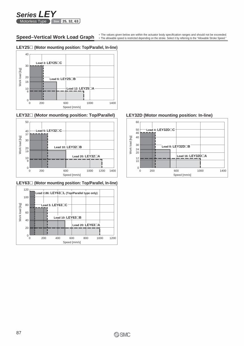
0
10
20
30
40
16
8
0 200 600 1000 1400
Speed [mm/s]
Work
load [kg]
Lead 6: LEY25 B
Lead 3: LEY25 C
Lead 12: LEY25 A
37
19
9
0 200 600 1000 14001200
50
40
30
20
10
0
Speed [mm/s]
Work
load [
kg]
Lead 20: LEY32 A
Lead 5: LEY32 C
Lead 10: LEY32 B
0 200 600 1000 1400
60
50
40
30
20
10
0
12
24
46
Speed [mm/s]
Work
load [kg]
Lead 4: LEY32D C
Lead 8: LEY32D B
Lead 16: LEY32D A
Speed [mm/s]
Work
load [
kg]
0
20
40
60
80
120
100
0 200 400 600 800 1000 1200
Lead 5: LEY63 C
Lead 2.86: LEY63 L (Top/Parallel type only)
Lead 20: LEY63 A
Lead 10: LEY63 B
∗ The values given below are within the actuator body specifi cation ranges and should not be exceeded.
∗ The allowable speed is restricted depending on the stroke. Select it by referring to the “Allowable Stroke Speed.”Speed–Vertical Work Load Graph
LEY25� (Motor mounting position: Top/Parallel, In-line)
LEY32� (Motor mounting position: Top/Parallel) LEY32D (Motor mounting position: In-line)
LEY63� (Motor mounting position: Top/Parallel, In-line)
87
Series LEYMotorless Type 25, 32, 63Size
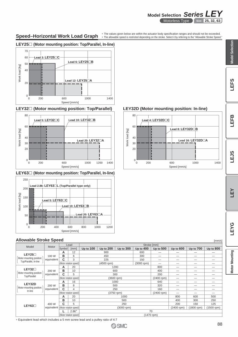
Speed [mm/s]
Wo
rk lo
ad
[kg
]
0 200 600 1000 14000
20
40
50
60
70
Lead 12: LEY25 A
Lead 3: LEY25 C
Lead 6: LEY25 B
Work
load [
kg
]
Speed [mm/s]
0 200 600 1000 140012000
20
30
40
60
80
Lead 20: LEY32 A
Lead 5: LEY32 C Lead 10: LEY32 B
Speed [mm/s]
Work
load [
kg
]
0 200 600 1000 14000
20
30
40
60
80
Lead 16: LEY32D A
Lead 4: LEY32D C
Lead 8: LEY32D B
Speed [mm/s]
Work
load [
kg]
0
50
100
150
200
250
0 200 400 600 800 12001000
Lead 2.86: LEY63 L (Top/Parallel type only)
Lead 20: LEY63 A
Lead 5: LEY63 C
Lead 10: LEY63 B
LEY25� (Motor mounting position: Top/Parallel, In-line)
LEY32� (Motor mounting position: Top/Parallel) LEY32D (Motor mounting position: In-line)
LEY63� (Motor mounting position: Top/Parallel, In-line)
∗ Equivalent lead which includes a 5 mm screw lead and a pulley ratio of 4:7
Allowable Stroke Speed [mm/s]
Speed–Horizontal Work Load Graph∗ The values given below are within the actuator body specifi cation ranges and should not be exceeded.
∗ The allowable speed is restricted depending on the stroke. Select it by referring to the “Allowable Stroke Speed.”
Model MotorLead Stroke [mm]
Symbol [mm] Up to 100 Up to 200 Up to 300 Up to 400 Up to 500 Up to 600 Up to 700 Up to 800
LEY25�Motor mounting position:
Top/Parallel, In-line
100 W
equivalent
A 12 900 600 — — — —
B 6 450 300 — — — —
C 3 225 150 — — — —
(Motor rotation speed) (4500 rpm) (3000 rpm) — — — —
LEY32�Motor mounting position:
Top/Parallel
200 W
equivalent
A 20 1200 800 — — —
B 10 600 400 — — —
C 5 300 200 — — —
(Motor rotation speed) (3600 rpm) (2400 rpm) — — —
LEY32DMotor mounting position:
In-line
200 W
equivalent
A 16 1000 640 — — —
B 8 500 320 — — —
C 4 250 160 — — —
(Motor rotation speed) (3750 rpm) (2400 rpm) — — —
LEY63� 400 W
equivalent
A 20 1000 800 600 500
B 10 500 400 300 250
C 5 250 200 150 125
(Motor rotation speed) (3000 rpm) (2400 rpm) (1800 rpm) (1500 rpm)
L 2.86∗ 70
(Motor rotation speed) (1470 rpm)
88
Model Selection Series LEYMotorless Type 25, 32, 63Size
LE
FS
LE
FB
LE
JS
LE
YL
EY
GM
od
el
Se
lec
tio
nM
oto
r M
ou
nti
ng

Ratio to rated torque [%]
Fo
rce
[N
]
500
400
300
200
100
0
6030 12090
Lead 3: LEY25 C
Lead 6: LEY25 B
Lead 12: LEY25 A
Ratio to rated torque [%]
Forc
e [
N]
600
500
400
300
200
100
0
6030 12090
Lead 5: LEY32 C
Lead 10: LEY32 B
Lead 20: LEY32 A
Ratio to rated torque [%]
Forc
e [
N]
800
700
600
500
400
300
200
100
0
6030 12090
Lead 4: LEY32D C
Lead 8: LEY32D B
Lead 16: LEY32D A
Ratio to rated torque [%]
Forc
e [
N]
0
500
1000
1500
2000
2500
3000
3500
30 60 90 120 150 180
Lead 2.86: LEY63 L(Top/Parallel type only)
Lead 5: LEY63 C
Lead 10: LEY63 B
Lead 20: LEY63 A
1
10
100
Stroke [mm]
Load: F
[N
] LEY63
LEY32
LEY25
0 100 200 300 400 500 600 700 800 900 1000
F
Workpiece
Centre of gravity
LEY63� (Motor mounting position: Top/Parallel, In-line)
LEY25� (Motor mounting position: Top/Parallel, In-line)
LEY32D� (Motor mounting position: In-line)LEY32� (Motor mounting position: Top/Parallel)
∗ When using the force control or speed control, set the maximum value to be less than 90 % of the rated torque.
Graph of Allowable Lateral Load on the Rod End (Guide)
∗ These graphs show an example of when the standard motor is mounted. Calculate the force based on the motor and driver used.Force Conversion Graph (Guide)
[Stroke] = [Actuator stroke] + [Distance from the rod end to the
centre of gravity of the workpiece]
89
Series LEYMotorless Type 25, 32, 63Size
90
LE
FS
LE
FB
LE
JS
LE
YL
EY
GM
od
el
Se
lec
tio
nM
oto
r M
ou
nti
ng
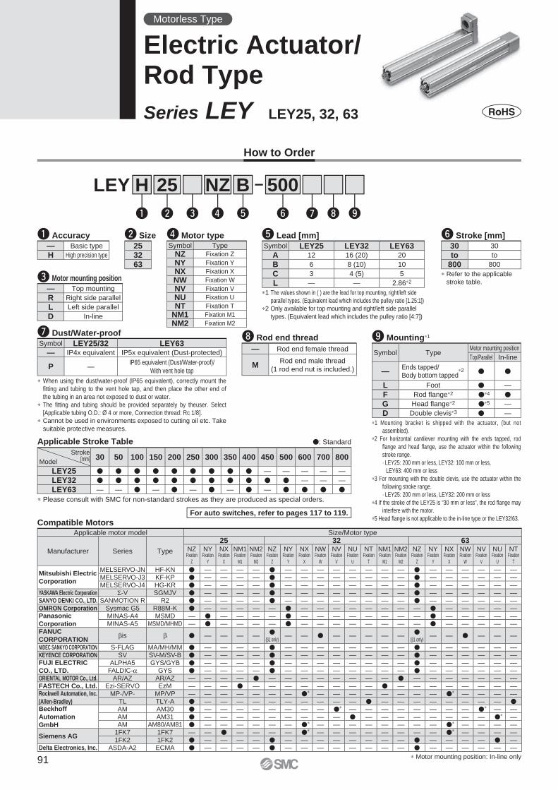
25 500B
w
LEY
e r t
H
q y u i o
NZ
u Dust/Water-proofSymbol LEY25/32 LEY63
— IP4x equivalent IP5x equivalent (Dust-protected)
P —IP65 equivalent (Dust/Water-proof)/
With vent hole tap
∗1 Mounting bracket is shipped with the actuator, (but not
assembled).
∗2 For horizontal cantilever mounting with the ends tapped, rod
fl ange and head fl ange, use the actuator within the following
stroke range.
· LEY25: 200 mm or less, LEY32: 100 mm or less,
LEY63: 400 mm or less
∗3 For mounting with the double clevis, use the actuator within the
following stroke range.
· LEY25: 200 mm or less, LEY32: 200 mm or less
∗4 If the stroke of the LEY25 is “30 mm or less”, the rod fl ange may
interfere with the motor.
∗5 Head fl ange is not applicable to the in-line type or the LEY32/63.
o Mounting∗1
Symbol TypeMotor mounting position
Top/Parallel In-line
—Ends tapped/Body bottom tapped
∗2 � �
L Foot � —
F Rod fl ange∗2 �∗4 �
G Head fl ange∗2 �∗5 —
D Double clevis∗3 � —
i Rod end thread
— Rod end female thread
MRod end male thread
(1 rod end nut is included.)
∗ Refer to the applicable
stroke table.
y Stroke [mm]
30 30
to to
800 800
∗1 The values shown in ( ) are the lead for top mounting, right/left side
parallel types. (Equivalent lead which includes the pulley ratio [1.25:1])
∗2 Only available for top mounting and right/left side parallel
types. (Equivalent lead which includes the pulley ratio [4:7])
t Lead [mm]Symbol LEY25 LEY32 LEY63
A 12 16 (20) 20
B 6 8 (10) 10
C 3 4 (5) 5
L — — 2.86∗2
For auto switches, refer to pages 117 to 119.
How to Order
q Accuracy
— Basic type
H High precision type
Applicable Stroke Table �: Standard
∗ Please consult with SMC for non-standard strokes as they are produced as special orders.
Stroke[mm]Model
30 50 100 150 200 250 300 350 400 450 500 600 700 800
LEY25 � � � � � � � � � — — — — —
LEY32 � � � � � � � � � � � — — —
LEY63 — — � — � — � — � — � � � �
e Motor mounting position
— Top mounting
R Right side parallel
L Left side parallel
D In-line
w Size
253263
Motorless Type
Electric Actuator/Rod Type
Series LEY LEY25, 32, 63
∗ When using the dust/water-proof (lP65 equivalent), correctly mount the
fi tting and tubing to the vent hole tap, and then place the other end of
the tubing in an area not exposed to dust or water.
∗ The fi tting and tubing should be provided separately by theuser. Select
[Applicable tubing O.D.: Ø 4 or more, Connection thread: Rc 1/8].
∗ Cannot be used in environments exposed to cutting oil etc. Take
suitable protective measures.
r Motor typeSymbol Type
NZ Fixation Z
NY Fixation Y
NX Fixation X
NW Fixation W
NV Fixation V
NU Fixation U
NT Fixation T
NM1 Fixation M1
NM2 Fixation M2
Compatible MotorsApplicable motor model Size/Motor type
Manufacturer Series Type
25 32 63NZ
Fixation Z
NYFixation
Y
NXFixation
X
NM1Fixation
M1
NM2Fixation
M2
NZFixation
Z
NYFixation
Y
NXFixation
X
NWFixation
W
NVFixation
V
NUFixation
U
NTFixation
T
NM1Fixation
M1
NM2Fixation
M2
NZFixation
Z
NYFixation
Y
NXFixation
X
NWFixation
W
NVFixation
V
NUFixation
U
NTFixation
T
Mitsubishi Electric
Corporation
MELSERVO-JN HF-KN � — — — — � — — — — — — — — � — — — — — —MELSERVO-J3 KF-KP � — — — — � — — — — — — — — � — — — — — —MELSERVO-J4 HG-KR � — — — — � — — — — — — — — � — — — — — —
YASKAWA Electric Corporation Σ-V SGMJV � — — — — � — — — — — — — — � — — — — — —SANYO DENKI CO., LTD. SANMOTION R R2 � — — — — � — — — — — — — — � — — — — — —OMRON Corporation Sysmac G5 R88M-K � — — — — — � — — — — — — — — � — — — — —Panasonic
Corporation
MINAS-A4 MSMD — � — — — — � — — — — — — — — � — — — — —MINAS-A5 MSMD/MHMD — � — — — — � — — — — — — — — � — — — — —
FANUC
CORPORATIONβis β � — — — —
�(β1 only)
— — � — — — — —�
(β1 only)— — � — — —
NIDEC SANKYO CORPORATION S-FLAG MA/MH/MM � — — — — � — — — — — — — — � — — — — — —KEYENCE CORPORATION SV SV-M/SV-B � — — — — � — — — — — — — — � — — — — — —FUJI ELECTRIC
CO., LTD.
ALPHA5 GYS/GYB � — — — — � — — — — — — — — � — — — — — —FALDIC-α GYS � — — — — � — — — — — — — — � — — — — — —
ORIENTAL MOTOR Co., Ltd. AR/AZ AR/AZ — — — — � — — — — — — — — � — — — — — — —FASTECH Co., Ltd. Ezi-SERVO EzM — — — � — — — — — — — — � — — — — — — — —Rockwell Automation, Inc.
(Allen-Bradley)
MP-/VP- MP/VP — — — — — — — �∗ — — — — — — — — �∗ — — — —TL TLY-A � — — — — — — — — — — � — — — — — — — — �
Beckhoff
Automation
GmbH
AM AM30 � — — — — — — — — �∗ — — — — — — — — �∗ — —AM AM31 � — — — — — — — — — � — — — — — — — — �∗ —AM AM80/AM81 � — — — — — — �∗ — — — — — — — — �∗ — — — —
Siemens AG1FK7 1FK7 — — � — — — — �∗ — — — — — — — — �∗ — — — —1FK2 1FK2 � — — — — � — — — — — — — — � — — — — � —
Delta Electronics, Inc. ASDA-A2 ECMA � — — — — � — — — — — — — — � — — — — — —
∗ Motor mounting position: In-line only91
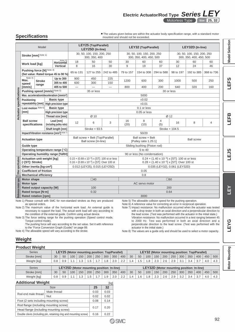
Specifi cations
Note 1) Please consult with SMC for non-standard strokes as they are produced as special orders.
Note 2) The maximum value of the horizontal work load. An external guide is necessary to support the load. The actual work load will vary according to the condition of the external guide. Confi rm using actual device.
Note 3) The force setting range for the pushing operation (Speed control mode, Torque control mode).The pushing force will vary according to the set value. Set it with reference to the “Force Conversion Graph (Guide)” on page 89.
Note 4) The allowable speed will vary according to the stroke.
Note 5) The allowable collision speed for the pushing operation.Note 6) A reference value for correcting an error in reciprocal operation.Note 7) Impact resistance: No malfunction occurred when the actuator was tested
with a drop tester in both an axial direction and a perpendicular direction to the lead screw. (Test was performed with the actuator in the initial state.)Vibration resistance: No malfunction occurred in a test ranging between 45 to 2000 Hz. Test was performed in both an axial direction and a perpendicular direction to the lead screw. (Test was performed with the actuator in the initial state.)
Note 8) The values are a guide only and should be used to select a motor capacity.
ModelLEY25 (Top/Parallel)
LEY25D (In-line)LEY32 (Top/Parallel) LEY32D (In-line)
Actu
ato
r sp
ecifi
cati
on
s
Stroke [mm] Note 1) 30, 50, 100, 150, 200, 250
300, 350, 400
30, 50, 100, 150, 200, 250
300, 350, 400, 450, 500
30, 50, 100, 150, 200, 250
300, 350, 400, 450, 500
Work load [kg]
Note 2)
Horizontal 18 50 50 30 60 60 30 60 60
Vertical 8 16 30 9 19 37 12 24 46
Pushing force [N] Note 3)
(Set value: Rated torque 45 to 90 %)65 to 131 127 to 255 242 to 485 79 to 157 154 to 308 294 to 588 98 to 197 192 to 385 368 to 736
Note 4)Max.speed[mm/s]
Stroke
range
Up to 300 900 450 2251200 600 300 1000 500 250
305 to 400 600 300 150
405 to 500 — — — 800 400 200 640 320 160
Pushing speed [mm/s] Note 5) 35 or less 30 or less
Max. acceleration/deceleration [mm/s2] 5000
Positioning
repeatability [mm]
Basic type ±0.02
High precision type ±0.01
Lost motion Note 6)
[mm]
Basic type 0.1 or less
High precision type 0.05 or less
Ball screw
specifi cations
Thread size [mm] Ø 10 Ø 12
Lead [mm]
(including pulley ratio)12 6 3
16
(20)
8
(10)
4
(5)16 8 4
Shaft length [mm] Stroke + 93.5 Stroke + 104.5
Impact/Vibration resistance [m/s2] Note 7) 50/20
Actuation typeBall screw + Belt (Top/Parallel)
Ball screw (In-line)
Ball screw + Belt
[Pulley ratio 1.25:1]Ball screw
Guide type Sliding bushing (Piston rod)
Operating temperature range [°C] 5 to 40
Operating humidity range [%RH] 90 or less (No condensation)
Oth
er s
peci
fi cat
ions Actuation unit weight [kg]
(∗[ST]: Stroke)
0.15 + (0.69 x 10⁻³) x [ST]: 100 st or less
0.16 + (0.69 x 10⁻³) x [ST]: Over 100 st
0.24 + (1.40 x 10⁻³) x [ST]: 100 st or less
0.28 + (1.40 x 10⁻³) x [ST]: Over 100 st
Other inertia [kg·cm2] 0.012 (LEY25), 0.015 (LEY25D) 0.035 (LEY32), 0.061 (LEY32D)
Coefficient of friction 0.05
Mechanical effi ciency 0.8
Refe
renc
e m
otor
spe
c. Motor shape �40 �60
Motor type AC servo motor
Rated output capacity [W] 100 200
Rated torque [N·m] 0.32 0.64
Rated rotation [rpm] 3000
Note 8)
Weight
Product Weight
[kg]Additional Weight
Series LEY25D (Motor mounting position: In-line) LEY32D (Motor mounting position: In-line)
Stroke [mm] 30 50 100 150 200 250 300 350 400 30 50 100 150 200 250 300 350 400 450 500
Weight [kg] 0.8 0.9 1.1 1.3 1.5 1.7 1.9 2.0 2.2 1.4 1.6 1.8 2.3 2.6 2.9 3.2 3.4 3.7 4.0 4.3
Series LEY25 (Motor mounting position: Top/Parallel) LEY32 (Motor mounting position: Top/Parallel)
Stroke [mm] 30 50 100 150 200 250 300 350 400 30 50 100 150 200 250 300 350 400 450 500
Weight [kg] 0.8 0.9 1.1 1.3 1.5 1.7 1.8 2.0 2.2 1.4 1.5 1.8 2.3 2.6 2.9 3.1 3.4 3.7 4.0 4.3
Size 25 32
Rod end male threadMale thread 0.03 0.03
Nut 0.02 0.02
Foot (2 sets including mounting screw) 0.08 0.14
Rod fl ange (including mounting screw)0.17 0.20
Head fl ange (including mounting screw)
Double clevis (including pin, retaining ring and mounting screw) 0.16 0.22
¡The values given below are within the actuator body specifi cation range, with a standard motor
mounted and should not be exceeded.
92
Electric Actuator/Rod Type Series LEYMotorless Type 25, 32Size
LE
FS
LE
FB
LE
JS
LE
YL
EY
GM
od
el
Se
lec
tio
nM
oto
r M
ou
nti
ng
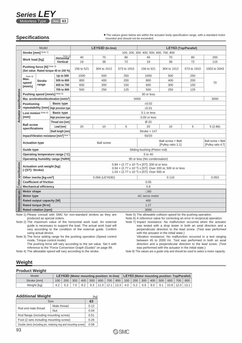
[kg]
Model LEY63D (In-line) LEY63 (Top/Parallel)
Actu
ato
r sp
ecifi
cati
on
s
Stroke [mm] Note 1) 100, 200, 300, 400, 500, 600, 700, 800
Work load [kg]
Note 2)Horizontal 40 70 80 40 70 80 200
Vertical 19 38 72 19 38 72 115
Pushing force [N] Note 3)
(Set value: Rated torque 45 to 150 %)156 to 521 304 to 1012 573 to 1910 156 to 521 304 to 1012 573 to 1910 1003 to 3343
Note 4)
Max.
speed
[mm/s]
Stroke
range
Up to 500 1000 500 250 1000 500 250
70505 to 600 800 400 200 800 400 200
605 to 700 600 300 150 600 300 150
705 to 800 500 250 125 500 250 125
Pushing speed [mm/s] Note 5) 30 or less
Max. acceleration/deceleration [mm/s2] 5000 3000
Positioning
repeatability [mm]
Basic type ±0.02
High precision type ±0.01
Lost motion Note 6)
[mm]
Basic type 0.1 or less
High precision type 0.05 or less
Ball screw
specifi cations
Thread size [mm] Ø 20
Lead [mm] 20 10 5 20 10 5 5 (2.86)
Shaft length [mm] Stroke + 147
Impact/Vibration resistance [m/s2] Note 7) 50/20
Actuation type Ball screwBall screw + Belt
[Pulley ratio 1:1]
Ball screw + Belt
[Pulley ratio 4:7]
Guide type Sliding bushing (Piston rod)
Operating temperature range [°C] 5 to 40
Operating humidity range [%RH] 90 or less (No condensation)
Oth
er s
pec
ifi ca
tio
ns
Actuation unit weight [kg](∗[ST]: Stroke)
0.84 + (2.77 x 10⁻³) x [ST]: 200 st or less
0.94 + (2.77 x 10⁻³) x [ST]: Over 200 st, 500 st or less
1.03 + (2.77 x 10⁻³) x [ST]: Over 500 st
Other inertia [kg·cm2] 0.056 (LEY63D) 0.110 0.053
Coefficient of friction 0.05
Mechanical effi ciency 0.8
Refe
renc
e m
otor
spe
c. Motor shape �60
Motor type AC servo motor
Rated output capacity [W] 400
Rated torque [N·m] 1.27
Rated rotation [rpm] 3000
Note 8)
Size 63
Rod end male threadMale thread 0.12
Nut 0.04
Rod fl ange (including mounting screw) 0.51
Foot (2 sets including mounting screw) 0.26
Double clevis (including pin, retaining ring and mounting screw) 0.58
Specifi cations
Model LEY63D (Motor mounting position: In-line) LEY63 (Motor mounting position: Top/Parallel)
Stroke [mm] 100 200 300 400 500 600 700 800 100 200 300 400 500 600 700 800
Weight [kg] 4.2 5.3 7.0 8.2 9.3 11.0 12.1 13.3 4.0 5.2 6.9 8.0 9.1 10.8 12.0 13.1
Weight
Product Weight
Additional Weight
Note 1) Please consult with SMC for non-standard strokes as they are
produced as special orders.
Note 2) The maximum value of the horizontal work load. An external
guide is necessary to support the load. The actual work load will
vary according to the condition of the external guide. Confi rm
using actual device.
Note 3) The force setting range for the pushing operation (Speed control
mode, Torque control mode).
The pushing force will vary according to the set value. Set it with
reference to the “Force Conversion Graph (Guide)” on page 89.
Note 4) The allowable speed will vary according to the stroke.
Note 5) The allowable collision speed for the pushing operation.
Note 6) A reference value for correcting an error in reciprocal operation.
Note 7) Impact resistance: No malfunction occurred when the actuator
was tested with a drop tester in both an axial direction and a
perpendicular direction to the lead screw. (Test was performed
with the actuator in the initial state.)
Vibration resistance: No malfunction occurred in a test ranging
between 45 to 2000 Hz. Test was performed in both an axial
direction and a perpendicular direction to the lead screw. (Test
was performed with the actuator in the initial state.)
Note 8) The values are a guide only and should be used to select a motor capacity.
¡The values given below are within the actuator body specifi cation range, with a standard motor
mounted and should not be exceeded.
93
Series LEYMotorless Type 63Size
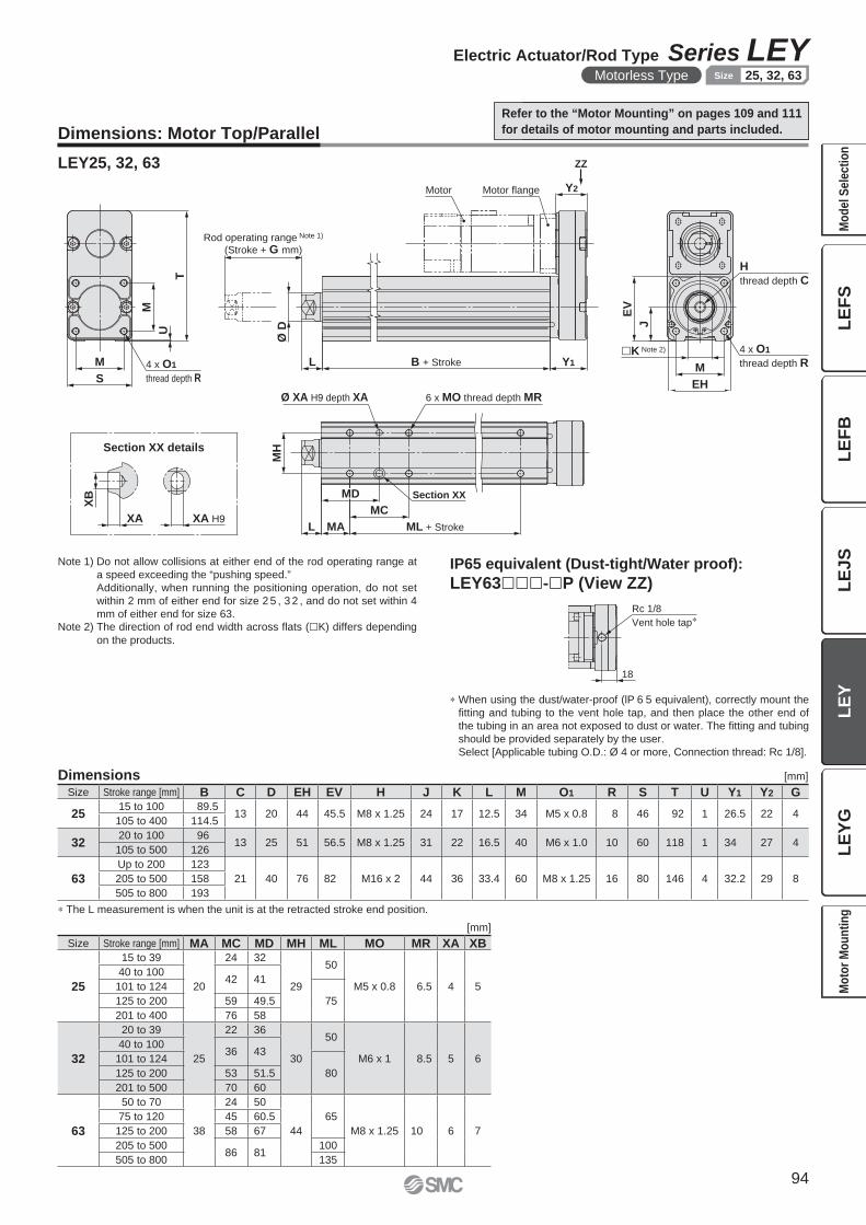
T
U
M
S
M 4 x O1
thread depth R
Y2
Y1B + StrokeL
Ø D
Rod operating range Note 1)
(Stroke + G mm)
H
thread depth C
4 x O1
thread depth R
EV
J
�K Note 2)
M
EH
Motor flangeMotor
ZZ
Ø XA H9 depth XA 6 x MO thread depth MR
MH
L MA
MD
MC
ML + Stroke
Section XX
XA H9
XB
XA
Rc 1/8
Vent hole tap∗
18
Dimensions: Motor Top/Parallel
LEY25, 32, 63
Note 1) Do not allow collisions at either end of the rod operating range at
a speed exceeding the “pushing speed.”
Additionally, when running the positioning operation, do not set
within 2 mm of either end for size 2 5 , 3 2 , and do not set within 4
mm of either end for size 63.Note 2) The direction of rod end width across fl ats (�K) differs depending
on the products.
Dimensions [mm]
∗ The L measurement is when the unit is at the retracted stroke end position.
Size Stroke range [mm] B C D EH EV H J K L M O1 R S T U Y1 Y2 G
2515 to 100 89.5
13 20 44 45.5 M8 x 1.25 24 17 12.5 34 M5 x 0.8 8 46 92 1 26.5 22 4105 to 400 114.5
3220 to 100 96
13 25 51 56.5 M8 x 1.25 31 22 16.5 40 M6 x 1.0 10 60 118 1 34 27 4105 to 500 126
63
Up to 200 123
21 40 76 82 M16 x 2 44 36 33.4 60 M8 x 1.25 16 80 146 4 32.2 29 8205 to 500 158
505 to 800 193
Section XX details
[mm]
Size Stroke range [mm] MA MC MD MH ML MO MR XA XB
25
15 to 39
20
24 32
29
50
M5 x 0.8 6.5 4 5
40 to 10042 41
101 to 124
75125 to 200 59 49.5
201 to 400 76 58
32
20 to 39
25
22 36
30
50
M6 x 1 8.5 5 6
40 to 10036 43
101 to 124
80125 to 200 53 51.5
201 to 500 70 60
63
50 to 70
38
24 50
44
65
M8 x 1.25 10 6 7
75 to 120 45 60.5
125 to 200 58 67
205 to 50086 81
100
505 to 800 135
IP65 equivalent (Dust-tight/Water proof):
LEY63���-�P (View ZZ)
∗ When using the dust/water-proof (lP 6 5 equivalent), correctly mount the
fi tting and tubing to the vent hole tap, and then place the other end of
the tubing in an area not exposed to dust or water. The fi tting and tubing
should be provided separately by the user.
Select [Applicable tubing O.D.: Ø 4 or more, Connection thread: Rc 1/8].
Refer to the “Motor Mounting” on pages 109 and 111
for details of motor mounting and parts included.
94
Electric Actuator/Rod Type Series LEYMotorless Type 25, 32, 63Size
LE
FS
LE
FB
LE
JS
LE
YL
EY
GM
od
el
Se
lec
tio
nM
oto
r M
ou
nti
ng
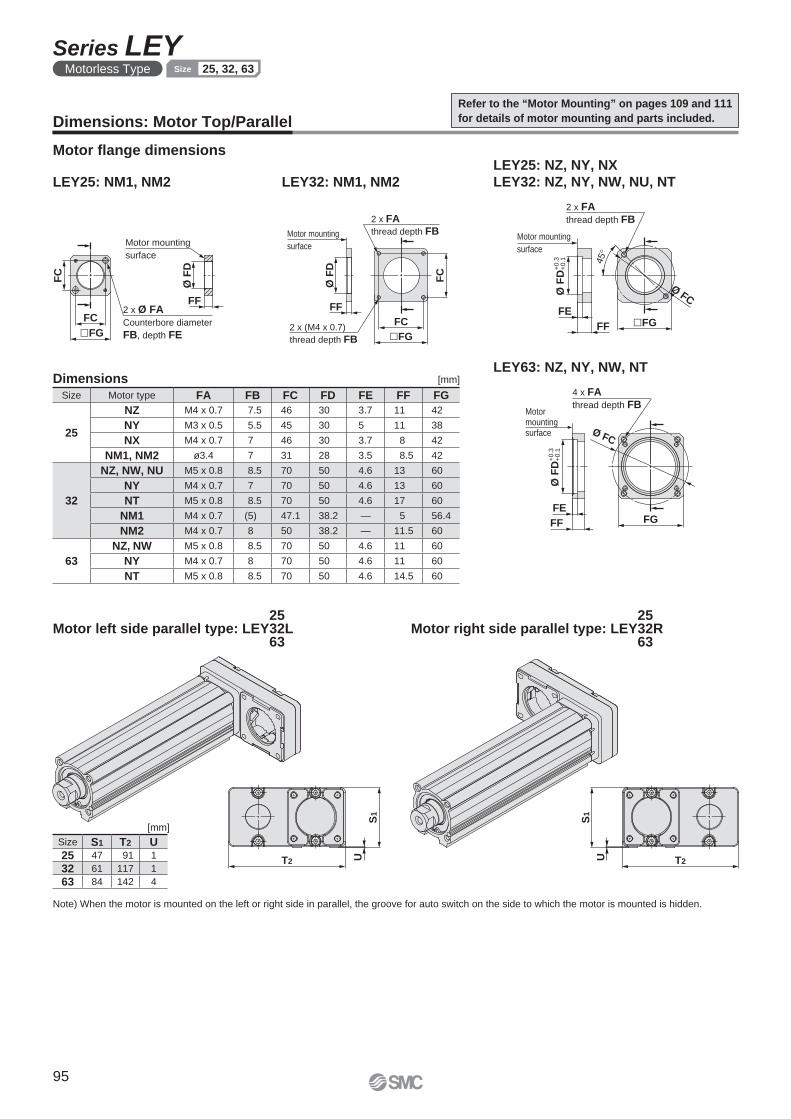
Motor mounting
surface
2 x Ø FA
Counterbore diameter
FB, depth FE
FF
Ø F
D
FC
FC
�FG �FG
FC
2 x FA
thread depth FB
FF
Ø F
D
FC
2 x (M4 x 0.7)
thread depth FB
Motor mounting
surface
FF
FE
2 x FA
thread depth FB
Ø FC
45
°
�FG
Motor mounting
surface
Ø F
D+
0.3
+
0.1
S1
T2 U T2
S1
U
Motormountingsurface
4 x FA
thread depth FB
FGFF
FE
Ø FC
Ø F
D+
0.3
+
0.1
LEY25: NZ, NY, NX
LEY32: NZ, NY, NW, NU, NT
Motor fl ange dimensions
LEY63: NZ, NY, NW, NT
LEY32: NM1, NM2LEY25: NM1, NM2
[mm]
Size S1 T2 U25 47 91 1
32 61 117 1
63 84 142 4
Dimensions: Motor Top/Parallel
Motor left side parallel type: LEY L253263
Motor right side parallel type: LEY R253263
Note) When the motor is mounted on the left or right side in parallel, the groove for auto switch on the side to which the motor is mounted is hidden.
Refer to the “Motor Mounting” on pages 109 and 111
for details of motor mounting and parts included.
Dimensions [mm]
Size Motor type FA FB FC FD FE FF FG
25
NZ M4 x 0.7 7.5 46 30 3.7 11 42
NY M3 x 0.5 5.5 45 30 5 11 38
NX M4 x 0.7 7 46 30 3.7 8 42
NM1, NM2 ø3.4 7 31 28 3.5 8.5 42
32
NZ, NW, NU M5 x 0.8 8.5 70 50 4.6 13 60
NY M4 x 0.7 7 70 50 4.6 13 60
NT M5 x 0.8 8.5 70 50 4.6 17 60
NM1 M4 x 0.7 (5) 47.1 38.2 — 5 56.4
NM2 M4 x 0.7 8 50 38.2 — 11.5 60
63
NZ, NW M5 x 0.8 8.5 70 50 4.6 11 60
NY M4 x 0.7 8 70 50 4.6 11 60
NT M5 x 0.8 8.5 70 50 4.6 14.5 60
95
Series LEYMotorless Type 25, 32, 63Size
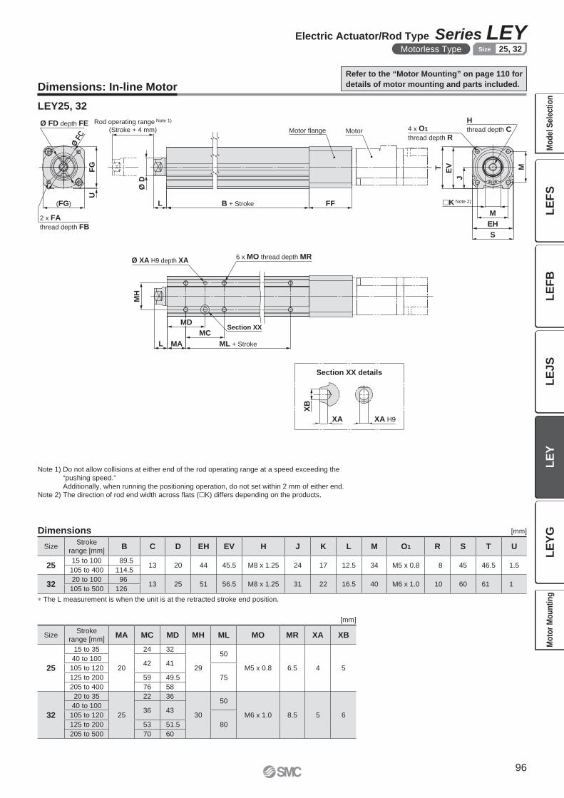
Ø FD depth FEMotorMotor flange
FF(FG) B + StrokeL
Rod operating range Note 1)
(Stroke + 4 mm)
H
thread depth C
M
S
EH
M
�K Note 2)
4 x O1
thread depth R
T EV
J
Ø F
C
2 x FA
thread depth FB
UF
G
Ø D
6 x MO thread depth MRØ XA H9 depth XA
MH
L MA
MD
MC
ML + Stroke
Section XX
XA H9
XB
XA
LEY25, 32
Dimensions [mm]
∗ The L measurement is when the unit is at the retracted stroke end position.
SizeStroke
range [mm]B C D EH EV H J K L M O1 R S T U
2515 to 100 89.5
13 20 44 45.5 M8 x 1.25 24 17 12.5 34 M5 x 0.8 8 45 46.5 1.5105 to 400 114.5
3220 to 100 96
13 25 51 56.5 M8 x 1.25 31 22 16.5 40 M6 x 1.0 10 60 61 1105 to 500 126
Section XX details
[mm]
SizeStroke
range [mm]MA MC MD MH ML MO MR XA XB
25
15 to 35
20
24 32
29
50
M5 x 0.8 6.5 4 5
40 to 10042 41
105 to 120
75125 to 200 59 49.5
205 to 400 76 58
32
20 to 35
25
22 36
30
50
M6 x 1.0 8.5 5 6
40 to 10036 43
105 to 120
80125 to 200 53 51.5
205 to 500 70 60
Dimensions: In-line Motor
Note 1) Do not allow collisions at either end of the rod operating range at a speed exceeding the
“pushing speed.”
Additionally, when running the positioning operation, do not set within 2 mm of either end.Note 2) The direction of rod end width across fl ats (�K) differs depending on the products.
Refer to the “Motor Mounting” on page 110 for
details of motor mounting and parts included.
96
Electric Actuator/Rod Type Series LEYMotorless Type 25, 32Size
LE
FS
LE
FB
LE
JS
LE
YL
EY
GM
od
el
Se
lec
tio
nM
oto
r M
ou
nti
ng

FF
FH Motor flange
Motor2 x FA through (depth FB)
(�FG)
FC
FC
Ø FD depth FE Motor flange
Motor
FE
FF(�FG)
FC
FC
Ø F
H
2 x FA
thread depth FBØ FD depth FE
LEY32: NM1LEY25: NM1, NM2
Dimensions: In-line Motor
Refer to the “Motor Mounting” on page 110 for
details of motor mounting and parts included.
LEY32: NM2
Dimensions [mm]
Size Motor type FA FB FC FD FE FF FG FH
25
NZ, NX M4 x 0.7 7.5 46 30 3.7 47 45 —
NY M3 x 0.5 6 45 30 4.2 47 45 —
NM1 ø3.4 17 31 22 2.5 36 45 19
NM2 ø3.4 28 31 30 3.5 56 45 30
32
NZ, NW, NU, NT M5 x 0.8 8.5 70 50 3.3 60 60 —
NY M4 x 0.7 8 70 50 3.3 60 60 —
NX M5 x 0.8 8.5 63 40 3.5 63 60 —
NV M4 x 0.7 8 63 40 3.5 63 60 —
NM1 M4 x 0.7 8 47.14 38.1 2 34 60 51.5
NM2 M4 x 0.7 8 50 36 3.3 60 60 —
Motor flange Motor
FF
øFD depth FE 2 x FA
thread depth FB
FC
(�FG)
FC
97
Series LEYMotorless Type 25, 32Size
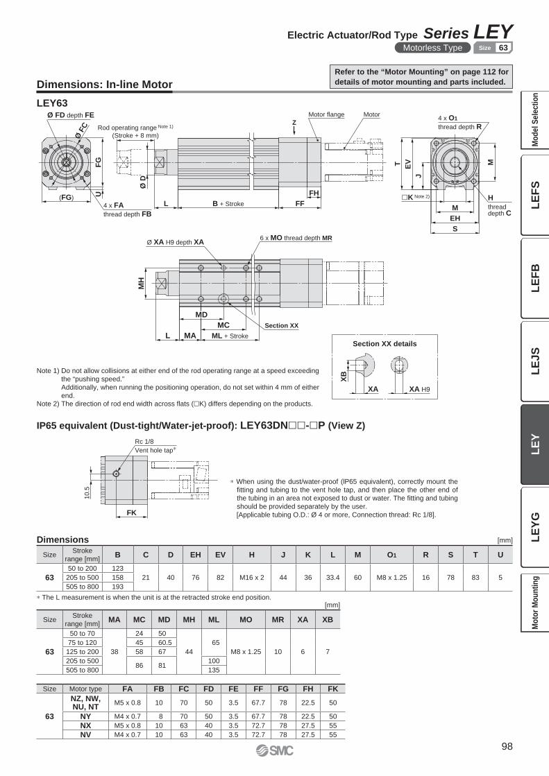
FK
10
.5
Rc 1/8
Vent hole tap∗
Ø F
C
FH
FF(FG)
B + StrokeL
Ø D
Rod operating range Note 1)
(Stroke + 8 mm)
M
S
EH
M
T EV
J
UF
G
Z
4 x FA
thread depth FB
Ø FD depth FE Motor flange Motor
H
threaddepth C
4 x O1
thread depth R
�K Note 2)
6 x MO thread depth MR
Section XX
Ø XA H9 depth XA
MH
L MA
MD
MC
ML + Stroke
XA H9
XB
XA
LEY63
Section XX details
Size Motor type FA FB FC FD FE FF FG FH FK
63
NZ, NW,NU, NT
M5 x 0.8 10 70 50 3.5 67.7 78 22.5 50
NY M4 x 0.7 8 70 50 3.5 67.7 78 22.5 50
NX M5 x 0.8 10 63 40 3.5 72.7 78 27.5 55
NV M4 x 0.7 10 63 40 3.5 72.7 78 27.5 55
[mm]
SizeStroke
range [mm]MA MC MD MH ML MO MR XA XB
63
50 to 70
38
24 50
44
65
M8 x 1.25 10 6 7
75 to 120 45 60.5
125 to 200 58 67
205 to 50086 81
100
505 to 800 135
Dimensions: In-line Motor
∗ When using the dust/water-proof (lP65 equivalent), correctly mount the
fi tting and tubing to the vent hole tap, and then place the other end of
the tubing in an area not exposed to dust or water. The fi tting and tubing
should be provided separately by the user.
[Applicable tubing O.D.: Ø 4 or more, Connection thread: Rc 1/8].
IP65 equivalent (Dust-tight/Water-jet-proof): LEY63DN��-�P (View Z)
Dimensions [mm]
∗ The L measurement is when the unit is at the retracted stroke end position.
Note 1) Do not allow collisions at either end of the rod operating range at a speed exceeding
the “pushing speed.”
Additionally, when running the positioning operation, do not set within 4 mm of either
end.Note 2) The direction of rod end width across fl ats (�K) differs depending on the products.
SizeStroke
range [mm]B C D EH EV H J K L M O1 R S T U
63
50 to 200 123
21 40 76 82 M16 x 2 44 36 33.4 60 M8 x 1.25 16 78 83 5205 to 500 158
505 to 800 193
Refer to the “Motor Mounting” on page 112 for
details of motor mounting and parts included.
98
Electric Actuator/Rod Type Series LEYMotorless Type 63Size
LE
FS
LE
FB
LE
JS
LE
YL
EY
GM
od
el
Se
lec
tio
nM
oto
r M
ou
nti
ng
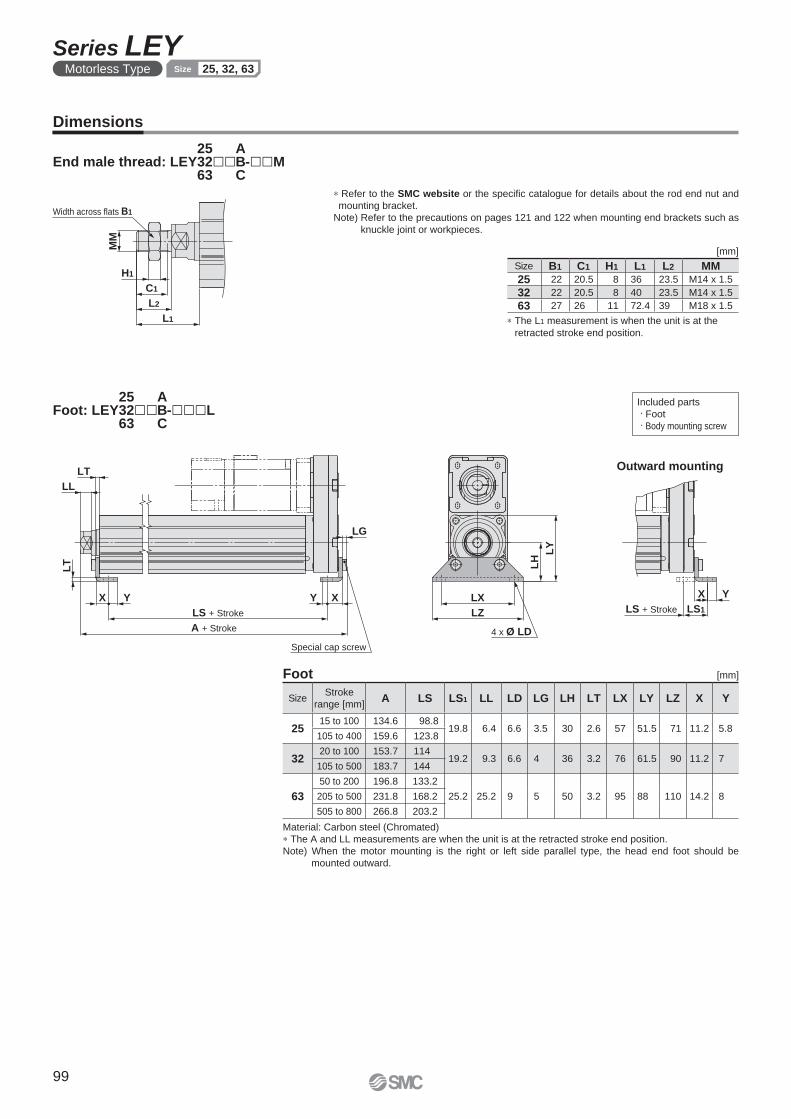
LY
LH
LX
LZ
LT
LL
LT
YX
A + Stroke
LS + Stroke
XY
LG
YX
LS1
4 x Ø LD
Special cap screw
LS + Stroke
MM
L1
L2
C1
H1
Width across flats B1
[mm]Foot
Material: Carbon steel (Chromated)
∗ The A and LL measurements are when the unit is at the retracted stroke end position.
Note) When the motor mounting is the right or left side parallel type, the head end foot should be
mounted outward.
Outward mounting
SizeStroke
range [mm]A LS LS1 LL LD LG LH LT LX LY LZ X Y
2515 to 100 134.6 98.8
19.8 6.4 6.6 3.5 30 2.6 57 51.5 71 11.2 5.8105 to 400 159.6 123.8
3220 to 100 153.7 114
19.2 9.3 6.6 4 36 3.2 76 61.5 90 11.2 7105 to 500 183.7 144
63
50 to 200 196.8 133.2
25.2 25.2 9 5 50 3.2 95 88 110 14.2 8205 to 500 231.8 168.2
505 to 800 266.8 203.2
Dimensions
Included parts
· Foot
· Body mounting screw
∗ Refer to the SMC website or the specifi c catalogue for details about the rod end nut and
mounting bracket.
Note) Refer to the precautions on pages 121 and 122 when mounting end brackets such as
knuckle joint or workpieces.
[mm]
∗ The L1 measurement is when the unit is at the
retracted stroke end position.
Size B1 C1 H1 L1 L2 MM25 22 20.5 8 36 23.5 M14 x 1.5
32 22 20.5 8 40 23.5 M14 x 1.5
63 27 26 11 72.4 39 M18 x 1.5
Foot: LEY �� -���L253263
ABC
End male thread: LEY �� -��M253263
ABC
99
Series LEYMotorless Type 25, 32, 63Size
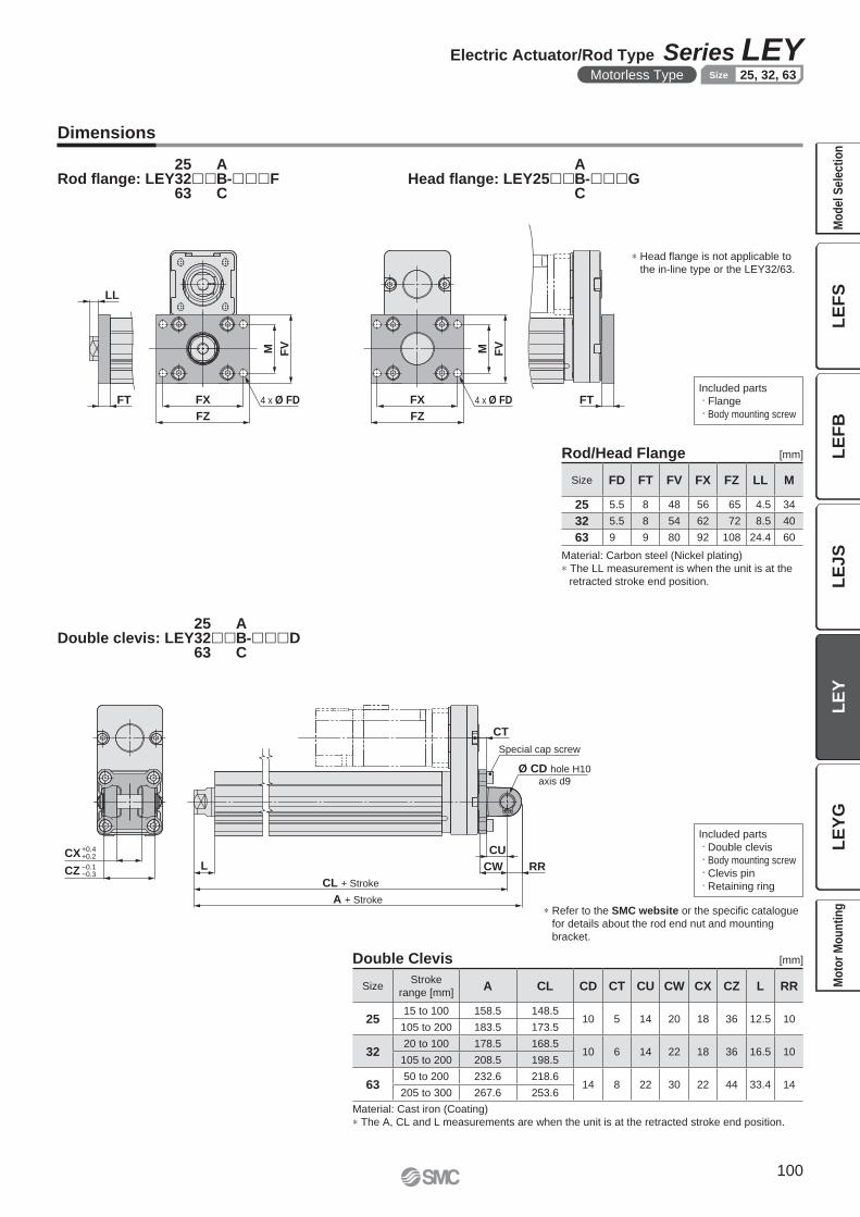
CX
CZ
CU
RRCWL
CL + Stroke
A + Stroke
CT
+0.4+0.2
−0.1−0.3
Special cap screw
Ø CD hole H10
axis d9
FZ
FX
FVM
FT
LL
FT
FZ
FX
M FV
4 x Ø FD 4 x Ø FD
[mm]Double Clevis
Material: Cast iron (Coating)
∗ The A, CL and L measurements are when the unit is at the retracted stroke end position.
SizeStroke
range [mm]A CL CD CT CU CW CX CZ L RR
2515 to 100 158.5 148.5
10 5 14 20 18 36 12.5 10105 to 200 183.5 173.5
3220 to 100 178.5 168.5
10 6 14 22 18 36 16.5 10105 to 200 208.5 198.5
6350 to 200 232.6 218.6
14 8 22 30 22 44 33.4 14205 to 300 267.6 253.6
Included parts
· Double clevis
· Body mounting screw
· Clevis pin
· Retaining ring
∗ Refer to the SMC website or the specifi c catalogue
for details about the rod end nut and mounting
bracket.
Dimensions
Included parts
· Flange
· Body mounting screw
[mm]
Material: Carbon steel (Nickel plating)
∗ The LL measurement is when the unit is at the
retracted stroke end position.
Rod/Head Flange
∗ Head fl ange is not applicable to
the in-line type or the LEY32/63.
Size FD FT FV FX FZ LL M
25 5.5 8 48 56 65 4.5 34
32 5.5 8 54 62 72 8.5 40
63 9 9 80 92 108 24.4 60
Rod fl ange: LEY �� -���F253263
ABC
Head fl ange: LEY25�� -���GABC
Double clevis: LEY �� -���D253263
ABC
100
Electric Actuator/Rod Type Series LEYMotorless Type 25, 32, 63Size
LE
FS
LE
FB
LE
JS
LE
YL
EY
GM
od
el
Se
lec
tio
nM
oto
r M
ou
nti
ng
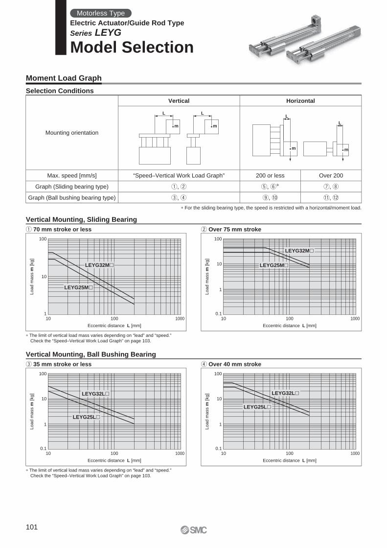
L L
m mL
m
L
m
Eccentric distance L [mm]
Load m
ass m
[kg]
0.1
1
100
10
10 100
LEYG32M
LEYG25M
1000
Eccentric distance L [mm]
Load m
ass m
[kg]
0.1
1
100
10
10 100
LEYG32L
LEYG25L
1000
Eccentric distance L [mm]
Load m
ass m
[kg]
0.1
1
100
10
10 100
LEYG32L
LEYG25L
1000
Eccentric distance L [mm]
Load m
ass m
[kg]
1
100
10
10 100
LEYG32M
LEYG25M
1000
Moment Load Graph
Selection Conditions
Vertical Mounting, Sliding Bearing
q 70 mm stroke or less w Over 75 mm stroke
Vertical Mounting, Ball Bushing Bearing
e 35 mm stroke or less r Over 40 mm stroke
∗ The limit of vertical load mass varies depending on “lead” and “speed.”
Check the “Speed–Vertical Work Load Graph” on page 103.
∗ The limit of vertical load mass varies depending on “lead” and “speed.”
Check the “Speed–Vertical Work Load Graph” on page 103.
∗ For the sliding bearing type, the speed is restricted with a horizontal/moment load.
Mounting orientation
Vertical Horizontal
Max. speed [mm/s] “Speed–Vertical Work Load Graph” 200 or less Over 200
Graph (Sliding bearing type) q, w t, y∗ u, i
Graph (Ball bushing bearing type) e, r o, !0 !1, !2
Motorless Type
Electric Actuator/Guide Rod Type
Series LEYG
Model Selection
101
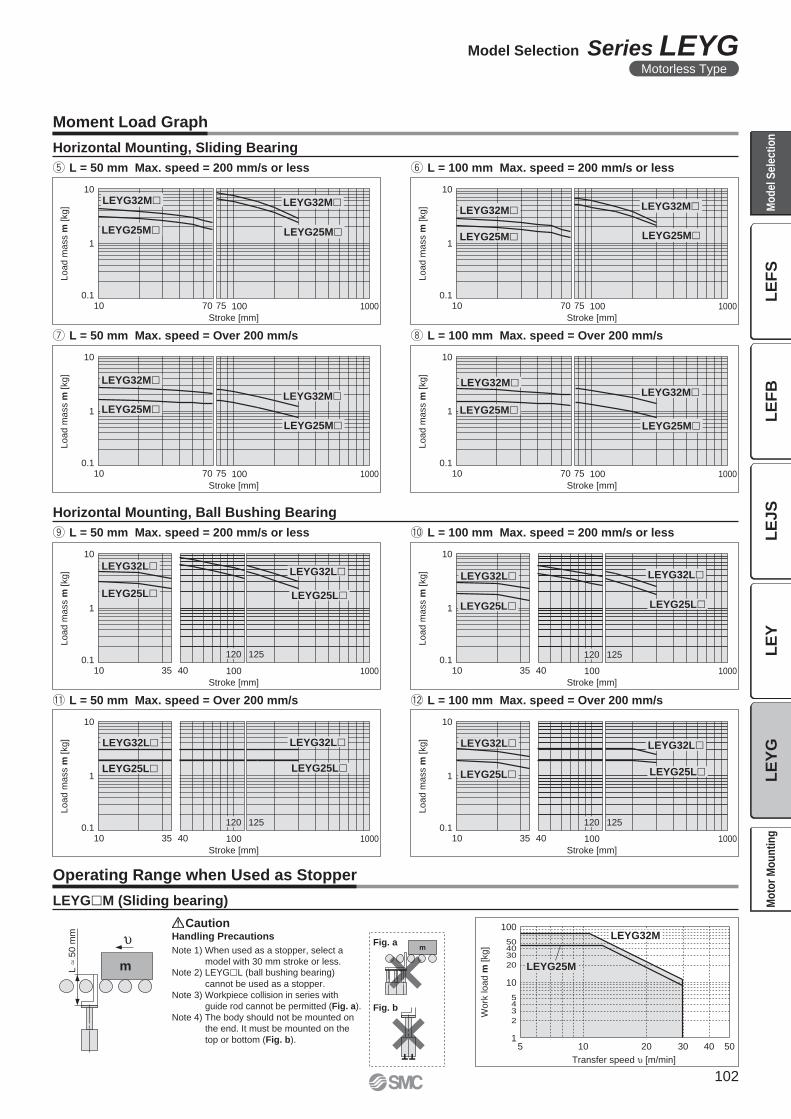
mL
50
mm
m
Transfer speed [m/min]
Work
load m
[kg]
504020 30105
100
504030
20
10
543
2
1
LEYG25M
LEYG32M
LEYG32M LEYG32M
LEYG25M LEYG25M
Load m
ass m
[kg]
0.1
1
10
Stroke [mm]
100 10007010 75
LEYG32M
LEYG25M
LEYG32M
LEYG25M
Load m
ass m
[kg]
0.1
1
10
Stroke [mm]
100 10007010 75
LEYG32M
LEYG25M
LEYG32M
LEYG25M
Lo
ad
ma
ss m
[kg
]
0.1
1
10
Stroke [mm]
100 10007010 75
LEYG32M
LEYG25M
LEYG32M
LEYG25MLoad
ma
ss m
[kg
]
0.1
1
10
Stroke [mm]
100 10007010 75
LEYG32LLEYG32L
LEYG25L LEYG25L
Load m
ass m
[kg]
0.1
1
10
Stroke [mm]
100 1000403510
120 125
LEYG32L LEYG32L
LEYG25L LEYG25L
Load m
ass m
[kg]
0.1
1
10
Stroke [mm]
100 1000403510
120 125
LEYG32L LEYG32L
LEYG25L LEYG25L
Load m
ass m
[kg]
0.1
1
10
Stroke [mm]
100 1000403510
120 125
LEYG32L LEYG32L
LEYG25L LEYG25L
Load m
ass m
[kg]
0.1
1
10
Stroke [mm]
100 1000403510
120 125
Fig. a
Fig. b
LEYG�M (Sliding bearing)
Caution
Operating Range when Used as Stopper
Horizontal Mounting, Sliding Bearing
t L = 50 mm Max. speed = 200 mm/s or less
u L = 50 mm Max. speed = Over 200 mm/s i L = 100 mm Max. speed = Over 200 mm/s
Handling Precautions
Note 1) When used as a stopper, select a
model with 30 mm stroke or less.Note 2) LEYG�L (ball bushing bearing)
cannot be used as a stopper.
Note 3) Workpiece collision in series with
guide rod cannot be permitted (Fig. a).
Note 4) The body should not be mounted on
the end. It must be mounted on the
top or bottom (Fig. b).
y L = 100 mm Max. speed = 200 mm/s or less
Horizontal Mounting, Ball Bushing Bearing
o L = 50 mm Max. speed = 200 mm/s or less
!1 L = 50 mm Max. speed = Over 200 mm/s !2 L = 100 mm Max. speed = Over 200 mm/s
!0 L = 100 mm Max. speed = 200 mm/s or less
Moment Load Graph
102
Model Selection Series LEYGMotorless Type
LE
FS
LE
FB
LE
JS
LE
YL
EY
GM
od
el
Se
lec
tio
nM
oto
r M
ou
nti
ng
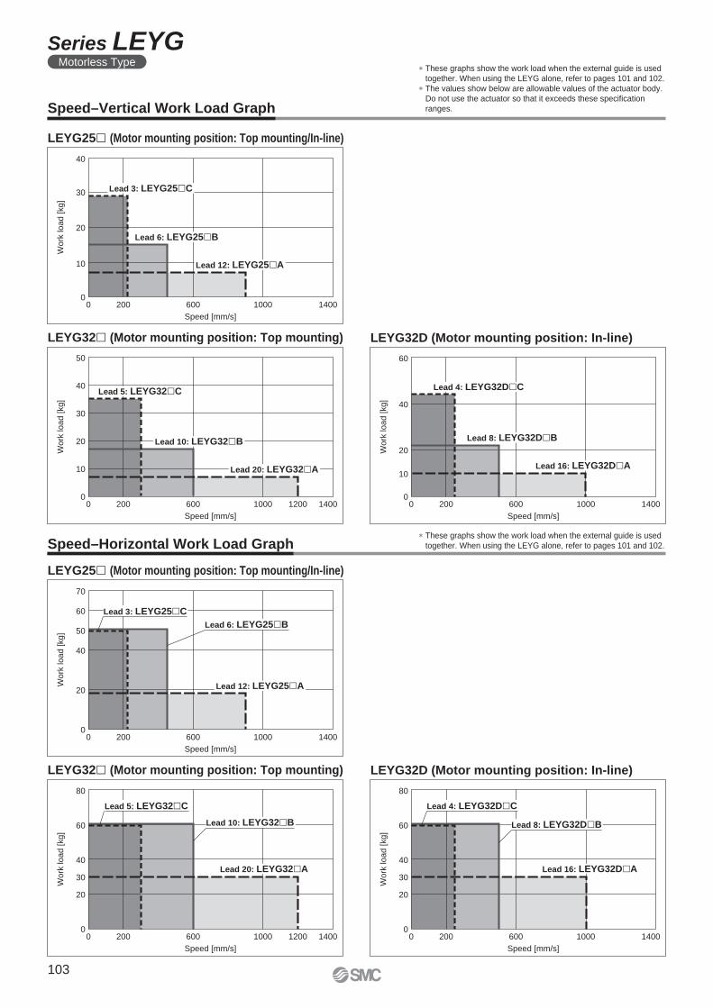
0 200 600 1000 1400
Speed [mm/s]
Wo
rk lo
ad
[kg
]
0
10
40
30
20
Lead 3: LEYG25 C
Lead 6: LEYG25 B
Lead 12: LEYG25 A
Lead 5: LEYG32 C
Lead 10: LEYG32 B
Lead 20: LEYG32 A
0 200 600 1000 14001200
Speed [mm/s]
Work
load [
kg]
0
10
50
30
40
20
0 200 600 1000 1400
Speed [mm/s]
Work
load [
kg]
0
10
60
40
20
Lead 4: LEYG32D C
Lead 8: LEYG32D B
Lead 16: LEYG32D A
0 200 600 1000 1400
Speed [mm/s]
Work
load [
kg]
0
20
70
50
60
40
Lead 12: LEYG25 A
Lead 3: LEYG25 C
Lead 6: LEYG25 B
Lead 20: LEYG32 A
0 200 600 1000 14001200
Speed [mm/s]
Work
load [kg]
0
20
80
60
40
30
Lead 5: LEYG32 C
Lead 10: LEYG32 B
Lead 16: LEYG32D A
0 200 600 1000 1400
Speed [mm/s]
Work
load [kg]
0
20
80
60
40
30
Lead 4: LEYG32D C
Lead 8: LEYG32D B
Speed–Vertical Work Load Graph
LEYG25� (Motor mounting position: Top mounting/In-line)
LEYG32� (Motor mounting position: Top mounting) LEYG32D (Motor mounting position: In-line)
Speed–Horizontal Work Load Graph
LEYG25� (Motor mounting position: Top mounting/In-line)
LEYG32� (Motor mounting position: Top mounting) LEYG32D (Motor mounting position: In-line)
∗ These graphs show the work load when the external guide is used
together. When using the LEYG alone, refer to pages 101 and 102.
∗ The values show below are allowable values of the actuator body.
Do not use the actuator so that it exceeds these specifi cation
ranges.
∗ These graphs show the work load when the external guide is used
together. When using the LEYG alone, refer to pages 101 and 102.
103
Series LEYGMotorless Type
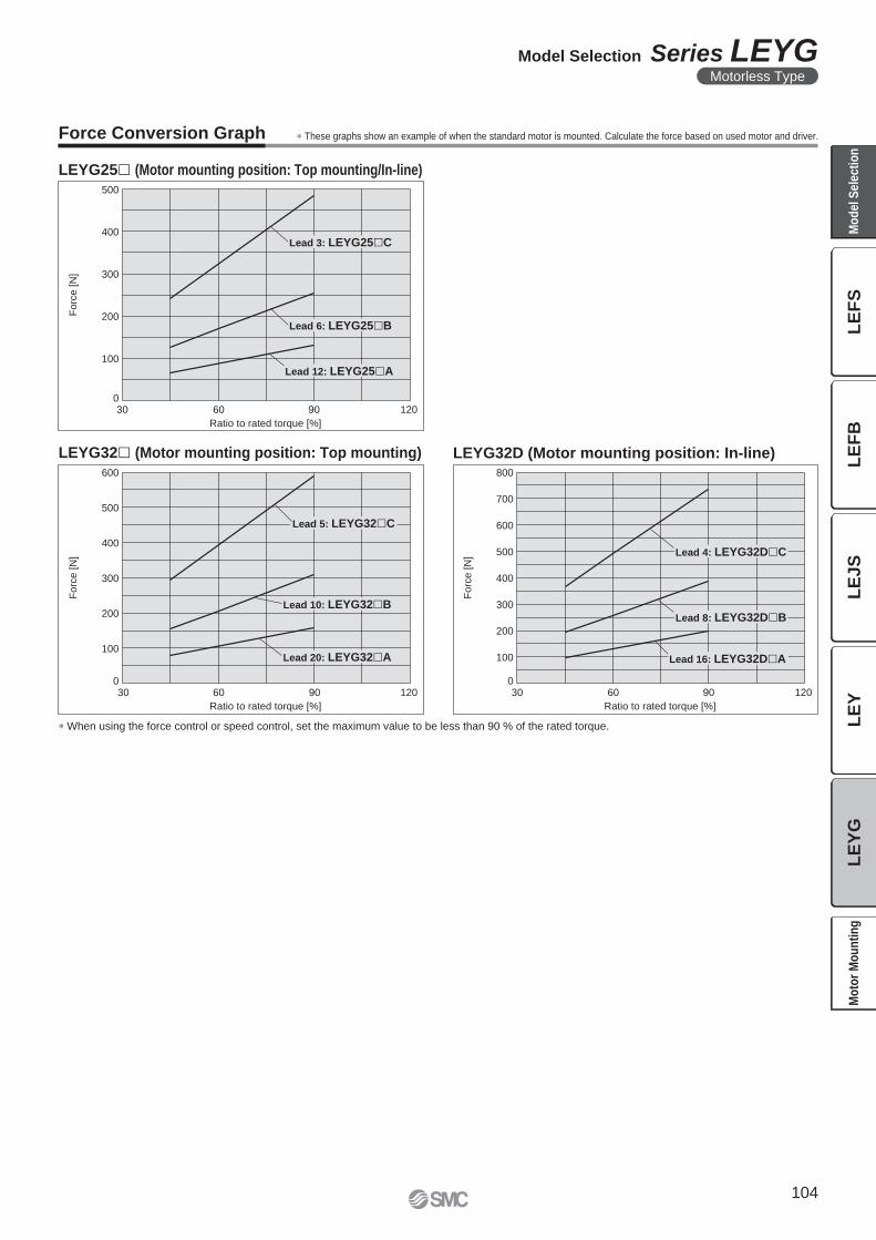
Fo
rce
[N
]
Ratio to rated torque [%]
500
400
300
200
100
06030 12090
Lead 3: LEYG25 C
Lead 6: LEYG25 B
Lead 12: LEYG25 A
Forc
e [
N]
Ratio to rated torque [%]
800
700
600
500
400
300
200
100
06030 12090
Lead 4: LEYG32D C
Lead 8: LEYG32D B
Lead 16: LEYG32D A
Forc
e [
N]
Ratio to rated torque [%]
600
500
400
300
200
100
06030 12090
Lead 5: LEYG32 C
Lead 10: LEYG32 B
Lead 20: LEYG32 A
Force Conversion Graph
LEYG25� (Motor mounting position: Top mounting/In-line)
LEYG32D (Motor mounting position: In-line)LEYG32� (Motor mounting position: Top mounting)
∗ When using the force control or speed control, set the maximum value to be less than 90 % of the rated torque.
∗ These graphs show an example of when the standard motor is mounted. Calculate the force based on used motor and driver.
104
Model Selection Series LEYGMotorless Type
LE
FS
LE
FB
LE
JS
LE
YL
EY
GM
od
el
Se
lec
tio
nM
oto
r M
ou
nti
ng
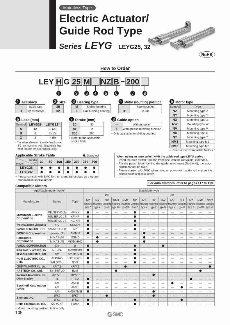
25 200B
w
LEY G
re t y u i
NZM
q
H
i Guide option
∗ Only available for sliding bearing.
— Without option
F With grease retaining function
y Lead [mm]
∗ The values shown in ( ) are the lead for size 3 2 top mounting type. (Equivalent lead which includes the pulley ratio [1.25:1])
Symbol LEYG25 LEYG32∗A 12 16 (20)
B 6 8 (10)
C 3 4 (5) ∗ Refer to the applicable stroke table.
u Stroke [mm]
30 30
to to
300 300
Compatible Motors
∗ Motor mounting position: In-line only
When using an auto switch with the guide rod type LEYG series
· Insert the auto switch from the front side with the rod (plate) extended.
· For the parts hidden behind the guide attachment (Rod end), the auto
switch cannot be fi xed.
· Please consult with SMC when using an auto switch at the rod end, as it is
produced as a special order.
How to Order
Applicable Stroke Table �: Standard
∗ Please consult with SMC for non-standard strokes as they are produced as special orders.
Stroke[mm]Model
30 50 100 150 200 250 300
LEYG25 � � � � � � �
LEYG32 � � � � � � �
w Size r Motor mounting positione Bearing type t Motor type
∗ Refer to the “Compatible Motors.”
q Accuracy
— Basic type
H High precision type
M Sliding bearing
L Ball bushing bearing
— Top mounting
D In-line
25
32
For auto switches, refer to pages 117 to 119.
Motorless Type
Electric Actuator/Guide Rod Type
Series LEYG LEYG25, 32
Applicable motor model Size/Motor type
Manufacturer Series Type
25 32
NZ
Mounting
type Z
NY
Mounting
type Y
NX
Mounting
type X
NM1
Mounting
type M1
NM2
Mounting
type M2
NZ
Mounting
type Z
NY
Mounting
type Y
NX
Mounting
type X
NW
Mounting
type W
NV
Mounting
type V
NU
Mounting
type U
NT
Mounting
type T
NM1
Mounting
type M1
NM2
Mounting
type M2
Mitsubishi ElectricCorporation
MELSERVO-JN HF-KN � — — — — � — — — — — — — —
MELSERVO-J3 KF-KP � — — — — � — — — — — — — —
MELSERVO-J4 HG-KR � — — — — � — — — — — — — —
YASKAWA Electric Corporation Σ-V SGMJV � — — — — � — — — — — — — —
SANYO DENKI CO., LTD. SANMOTION R R2 � — — — — � — — — — — — — —
OMRON Corporation Sysmac G5 R88M-K � — — — — — � — — — — — — —
PanasonicCorporation
MINAS-A4 MSMD — � — — — — � — — — — — — —
MINAS-A5 MSMD/MHMD — � — — — — � — — — — — — —
FANUC CORPORATION βis β � — — — — � — — � — — — — —
NIDEC SANKYO CORPORATION S-FLAG MA/MH/MM � — — — — � — — — — — — — —
KEYENCE CORPORATION SV SV-M/SV-B � — — — — � — — — — — — — —
FUJI ELECTRIC CO., LTD.
ALPHA5 GYS/GYB � — — — — � — — — — — — — —
FALDIC-α GYS � — — — — � — — — — — — — —
ORIENTAL MOTOR Co., Ltd. AR/AZ AR/AZ — — — — � — — — — — — — — �
FASTECH Co., Ltd. Ezi-SERVO EzM — — — � — — — — — — — — � —
Rockwell Automation, Inc.
(Allen-Bradley)
MP-/VP- MP/VP — — — — — — — �∗ — — — — — —
TL TLY-A � — — — — — — — — — — � — —
Beckhoff Automation
GmbH
AM AM30 � — — — — — — — — �∗ — — — —
AM AM31 � — — — — — — — — — � — — —
AM AM80/AM81 � — — — — — — �∗ — — — — — —
Siemens AG1FK7 1FK7 — — � — — — — �∗ — — — — — —
1FK2 1FK2 � — — — — � — — — � — — —
Delta Electronics, Inc. ASDA-A2 ECMA � — — — — � — — — — — — — —
Symbol Type
NZ Mounting type Z
NY Mounting type Y
NX Mounting type X
NW Mounting type W
NV Mounting type V
NU Mounting type U
NT Mounting type T
NM1 Mounting type M1
NM2 Mounting type M2
105
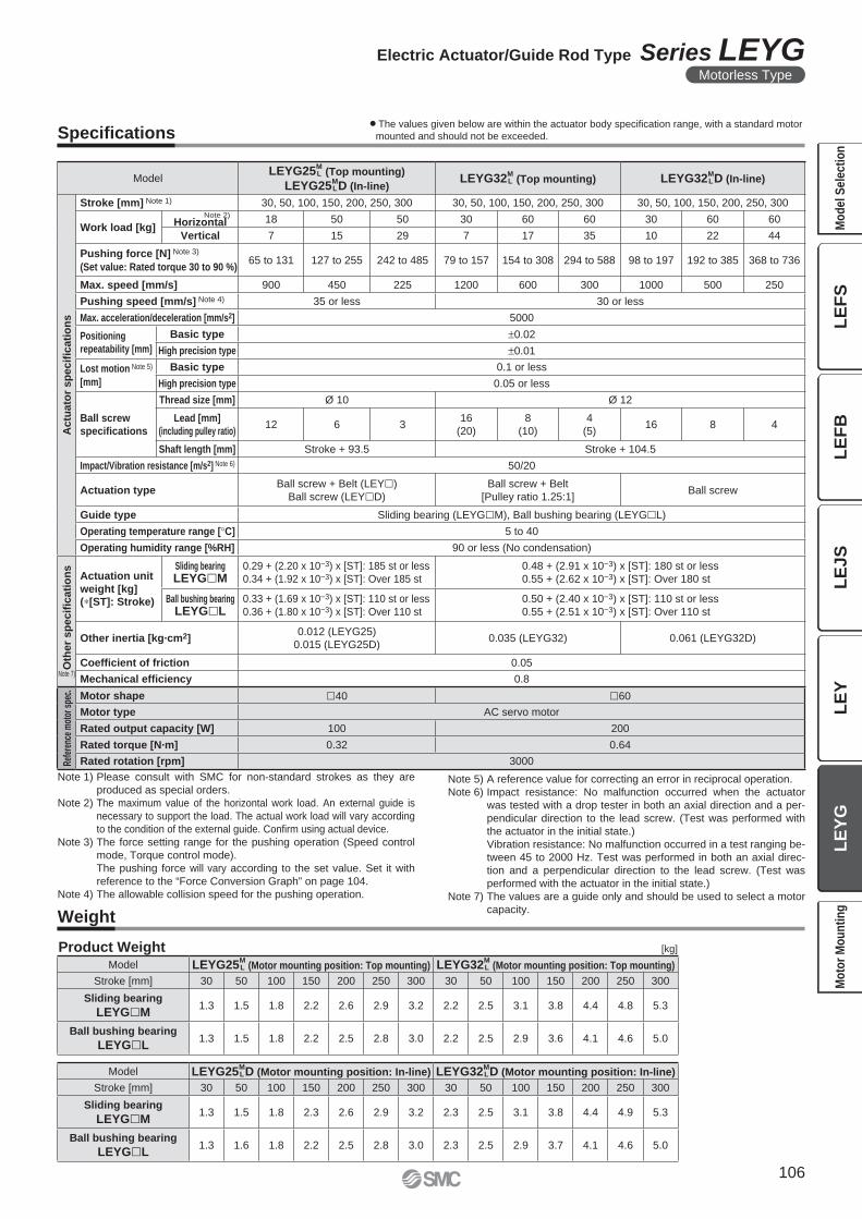
Specifi cations
Weight
[kg]Product Weight
Note 1) Please consult with SMC for non-standard strokes as they are
produced as special orders.
Note 2) The maximum value of the horizontal work load. An external guide is
necessary to support the load. The actual work load will vary according
to the condition of the external guide. Confi rm using actual device.
Note 3) The force setting range for the pushing operation (Speed control
mode, Torque control mode).
The pushing force will vary according to the set value. Set it with
reference to the “Force Conversion Graph” on page 104.
Note 4) The allowable collision speed for the pushing operation.
Note 5) A reference value for correcting an error in reciprocal operation.
Note 6) Impact resistance: No malfunction occurred when the actuator
was tested with a drop tester in both an axial direction and a per-
pendicular direction to the lead screw. (Test was performed with
the actuator in the initial state.)
Vibration resistance: No malfunction occurred in a test ranging be-
tween 45 to 2000 Hz. Test was performed in both an axial direc-
tion and a perpendicular direction to the lead screw. (Test was
performed with the actuator in the initial state.)
Note 7) The values are a guide only and should be used to select a motor
capacity.
ModelLEYG25
M L (Top mounting)
LEYG25M LD (In-line)
LEYG32M L (Top mounting) LEYG32
M LD (In-line)
Actu
ato
r sp
ecifi
cati
on
s
Stroke [mm] Note 1) 30, 50, 100, 150, 200, 250, 300 30, 50, 100, 150, 200, 250, 300 30, 50, 100, 150, 200, 250, 300
Work load [kg]
Note 2)Horizontal 18 50 50 30 60 60 30 60 60
Vertical 7 15 29 7 17 35 10 22 44
Pushing force [N] Note 3)
(Set value: Rated torque 30 to 90 %)65 to 131 127 to 255 242 to 485 79 to 157 154 to 308 294 to 588 98 to 197 192 to 385 368 to 736
Max. speed [mm/s] 900 450 225 1200 600 300 1000 500 250
Pushing speed [mm/s] Note 4) 35 or less 30 or less
Max. acceleration/deceleration [mm/s2] 5000
Positioning
repeatability [mm]
Basic type ±0.02
High precision type ±0.01
Lost motion Note 5)
[mm]
Basic type 0.1 or less
High precision type 0.05 or less
Ball screw
specifi cations
Thread size [mm] Ø 10 Ø 12
Lead [mm]
(including pulley ratio)12 6 3
16
(20)
8
(10)
4
(5)16 8 4
Shaft length [mm] Stroke + 93.5 Stroke + 104.5
Impact/Vibration resistance [m/s2] Note 6) 50/20
Actuation typeBall screw + Belt (LEY�)
Ball screw (LEY�D)
Ball screw + Belt
[Pulley ratio 1.25:1]Ball screw
Guide type Sliding bearing (LEYG�M), Ball bushing bearing (LEYG�L)
Operating temperature range [°C] 5 to 40
Operating humidity range [%RH] 90 or less (No condensation)
Oth
er
sp
ec
ifi c
ati
on
s
Actuation unit
weight [kg](∗[ST]: Stroke)
Sliding bearingLEYG�M
0.29 + (2.20 x 10⁻³) x [ST]: 185 st or less
0.34 + (1.92 x 10⁻³) x [ST]: Over 185 st
0.48 + (2.91 x 10⁻³) x [ST]: 180 st or less
0.55 + (2.62 x 10⁻³) x [ST]: Over 180 st
Ball bushing bearingLEYG�L
0.33 + (1.69 x 10⁻³) x [ST]: 110 st or less
0.36 + (1.80 x 10⁻³) x [ST]: Over 110 st
0.50 + (2.40 x 10⁻³) x [ST]: 110 st or less
0.55 + (2.51 x 10⁻³) x [ST]: Over 110 st
Other inertia [kg·cm2]0.012 (LEYG25)
0.015 (LEYG25D)0.035 (LEYG32) 0.061 (LEYG32D)
Coefficient of friction 0.05
Mechanical effi ciency 0.8
Refe
renc
e m
otor
spe
c. Motor shape �40 �60
Motor type AC servo motor
Rated output capacity [W] 100 200
Rated torque [N·m] 0.32 0.64
Rated rotation [rpm] 3000
Model LEYG25M LD (Motor mounting position: In-line) LEYG32
M LD (Motor mounting position: In-line)
Stroke [mm] 30 50 100 150 200 250 300 30 50 100 150 200 250 300
Sliding bearing
LEYG�M1.3 1.5 1.8 2.3 2.6 2.9 3.2 2.3 2.5 3.1 3.8 4.4 4.9 5.3
Ball bushing bearing
LEYG�L1.3 1.6 1.8 2.2 2.5 2.8 3.0 2.3 2.5 2.9 3.7 4.1 4.6 5.0
Model LEYG25M L (Motor mounting position: Top mounting) LEYG32
M L (Motor mounting position: Top mounting)
Stroke [mm] 30 50 100 150 200 250 300 30 50 100 150 200 250 300
Sliding bearing
LEYG�M1.3 1.5 1.8 2.2 2.6 2.9 3.2 2.2 2.5 3.1 3.8 4.4 4.8 5.3
Ball bushing bearing
LEYG�L1.3 1.5 1.8 2.2 2.5 2.8 3.0 2.2 2.5 2.9 3.6 4.1 4.6 5.0
Note 7)
¡The values given below are within the actuator body specifi cation range, with a standard motor
mounted and should not be exceeded.
106
Electric Actuator/Guide Rod Type Series LEYGMotorless Type
LE
FS
LE
FB
LE
JS
LE
YL
EY
GM
od
el
Se
lec
tio
nM
oto
r M
ou
nti
ng
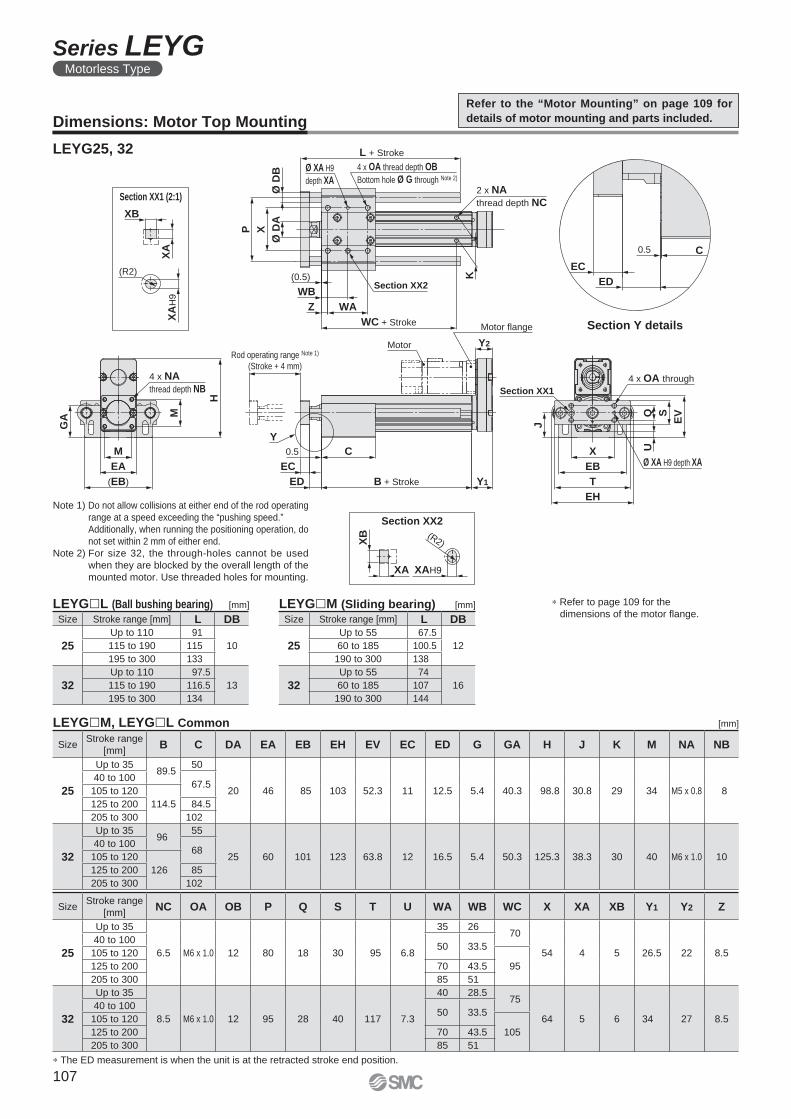
C
EC
ED
0.5
Motor flange
Motor
C
Y1
Y2
EC
ED
Rod operating range Note 1)
(Stroke + 4 mm)
0.5
B + Stroke
Y
K
H
4 x NA
thread depth NB
M
(EB)
EA
M
GA EVSQ
U
EH
T
EB
X
J
2 x NA
thread depth NC
WC + Stroke
Section XX2
WA
WB
(0.5)
Z
P
Ø D
B
X
Ø D
A
L + Stroke
Ø XA H9
depth XA
4 x OA thread depth OB
Bottom hole Ø G through Note 2)
Section XX1
4 x OA through
Ø XA H9 depth XA
XA
H9
(R2)
XB
XA
XA
XB (R2)
XAH9
Section Y details
Section XX1 (2:1)
[mm]LEYG�L (Ball bushing bearing)
LEYG�M, LEYG�L Common
[mm]LEYG�M (Sliding bearing)
∗ The ED measurement is when the unit is at the retracted stroke end position.
Section XX2
[mm]
SizeStroke range
[mm]NC OA OB P Q S T U WA WB WC X XA XB Y1 Y2 Z
25
Up to 35
6.5 M6 x 1.0 12 80 18 30 95 6.8
35 26 70
54 4 5 26.5 22 8.5
40 to 10050 33.5
105 to 120
95125 to 200 70 43.5
205 to 300 85 51
32
Up to 35
8.5 M6 x 1.0 12 95 28 40 117 7.3
40 28.5 75
64 5 6 34 27 8.5
40 to 10050 33.5
105 to 120
105125 to 200 70 43.5
205 to 300 85 51
Size Stroke range [mm] L DB
25
Up to 55 67.5
1260 to 185 100.5
190 to 300 138
32
Up to 55 74
1660 to 185 107
190 to 300 144
SizeStroke range
[mm]B C DA EA EB EH EV EC ED G GA H J K M NA NB
25
Up to 3589.5
50
20 46 85 103 52.3 11 12.5 5.4 40.3 98.8 30.8 29 34 M5 x 0.8 8
40 to 10067.5
105 to 120
114.5125 to 200 84.5
205 to 300 102
32
Up to 3596
55
25 60 101 123 63.8 12 16.5 5.4 50.3 125.3 38.3 30 40 M6 x 1.0 10
40 to 10068
105 to 120
126125 to 200 85
205 to 300 102
Size Stroke range [mm] L DB
25
Up to 110 91
10115 to 190 115
195 to 300 133
32
Up to 110 97.5
13115 to 190 116.5
195 to 300 134
∗ Refer to page 109 for the
dimensions of the motor fl ange.
Dimensions: Motor Top Mounting
LEYG25, 32
Refer to the “Motor Mounting” on page 109 for
details of motor mounting and parts included.
Note 1) Do not allow collisions at either end of the rod operating
range at a speed exceeding the “pushing speed.”
Additionally, when running the positioning operation, do
not set within 2 mm of either end.
Note 2) For size 32, the through-holes cannot be used
when they are blocked by the overall length of the
mounted motor. Use threaded holes for mounting.
107
Series LEYGMotorless Type
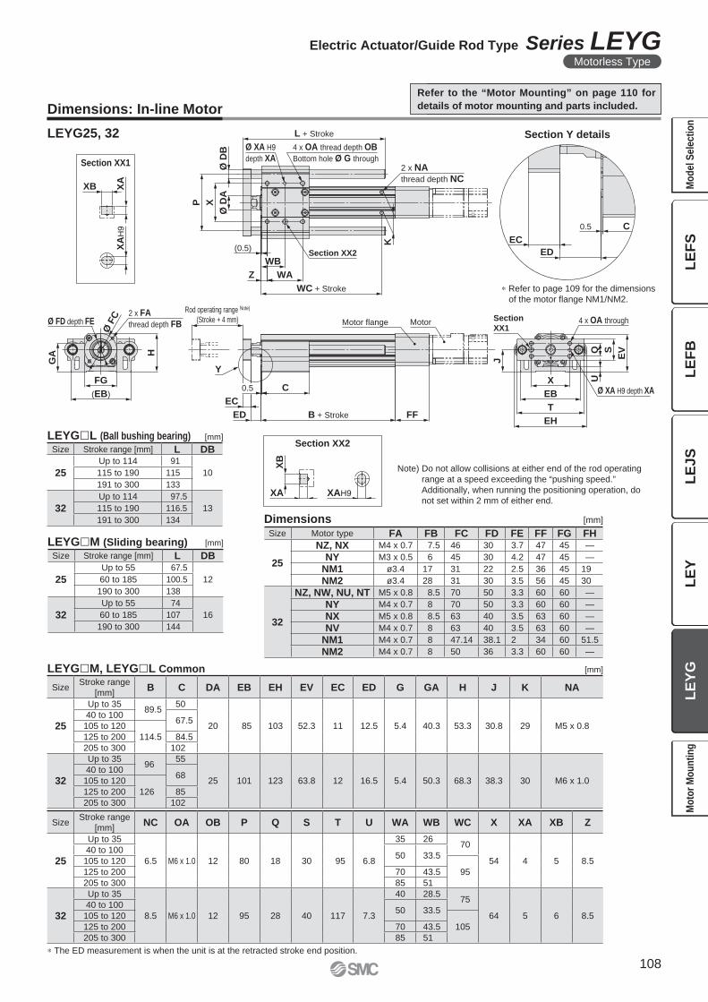
C
EC
ED
0.5
MotorMotor flange
FF
C
EC
ED
Rod operating range Note)
(Stroke + 4 mm)
0.5
B + Stroke
Y
H
(EB)
FG
Ø F
C
EVSQ
U
J
EH
T
EB
X
GA
L + Stroke
Ø D
B
P
Ø D
A
X
WC + Stroke
WAZ
(0.5)
K
Section
XX1
Ø XA H9 depth XA
4 x OA through2 x FA
thread depth FBØ FD depth FE
4 x OA thread depth OB
Bottom hole Ø G through
Ø XA H9
depth XA
Section XX2
2 x NA
thread depth NC
WB
XA
H9
XB XA
XA
XB
XAH9
Section Y details
Section XX2
Section XX1
[mm]LEYG�M (Sliding bearing)
[mm]
∗ The ED measurement is when the unit is at the retracted stroke end position.
Size Stroke range [mm] L DB
25
Up to 55 67.5
1260 to 185 100.5
190 to 300 138
32
Up to 55 74
1660 to 185 107
190 to 300 144
Refer to the “Motor Mounting” on page 110 for
details of motor mounting and parts included.
Note) Do not allow collisions at either end of the rod operating
range at a speed exceeding the “pushing speed.”
Additionally, when running the positioning operation, do
not set within 2 mm of either end.
Dimensions: In-line Motor
LEYG25, 32
[mm]LEYG�L (Ball bushing bearing)
Size Stroke range [mm] L DB
25
Up to 114 91
10115 to 190 115
191 to 300 133
32
Up to 114 97.5
13115 to 190 116.5
191 to 300 134
∗ Refer to page 109 for the dimensions
of the motor fl ange NM1/NM2.
Dimensions [mm]
Size Motor type FA FB FC FD FE FF FG FH
25
NZ, NX M4 x 0.7 7.5 46 30 3.7 47 45 —
NY M3 x 0.5 6 45 30 4.2 47 45 —
NM1 ø3.4 17 31 22 2.5 36 45 19
NM2 ø3.4 28 31 30 3.5 56 45 30
32
NZ, NW, NU, NT M5 x 0.8 8.5 70 50 3.3 60 60 —
NY M4 x 0.7 8 70 50 3.3 60 60 —
NX M5 x 0.8 8.5 63 40 3.5 63 60 —
NV M4 x 0.7 8 63 40 3.5 63 60 —
NM1 M4 x 0.7 8 47.14 38.1 2 34 60 51.5
NM2 M4 x 0.7 8 50 36 3.3 60 60 —
SizeStroke range
[mm]NC OA OB P Q S T U WA WB WC X XA XB Z
25
Up to 35
6.5 M6 x 1.0 12 80 18 30 95 6.8
35 26 70
54 4 5 8.5
40 to 10050 33.5
105 to 120
95125 to 200 70 43.5
205 to 300 85 51
32
Up to 35
8.5 M6 x 1.0 12 95 28 40 117 7.3
40 28.5 75
64 5 6 8.5
40 to 10050 33.5
105 to 120
105125 to 200 70 43.5
205 to 300 85 51
LEYG�M, LEYG�L Common [mm]
SizeStroke range
[mm]B C DA EB EH EV EC ED G GA H J K NA
25
Up to 3589.5
50
20 85 103 52.3 11 12.5 5.4 40.3 53.3 30.8 29 M5 x 0.8
40 to 10067.5
105 to 120
114.5125 to 200 84.5
205 to 300 102
32
Up to 3596
55
25 101 123 63.8 12 16.5 5.4 50.3 68.3 38.3 30 M6 x 1.0
40 to 10068
105 to 120
126125 to 200 85
205 to 300 102
108
Electric Actuator/Guide Rod Type Series LEYGMotorless Type
LE
FS
LE
FB
LE
JS
LE
YL
EY
GM
od
el
Se
lec
tio
nM
oto
r M
ou
nti
ng
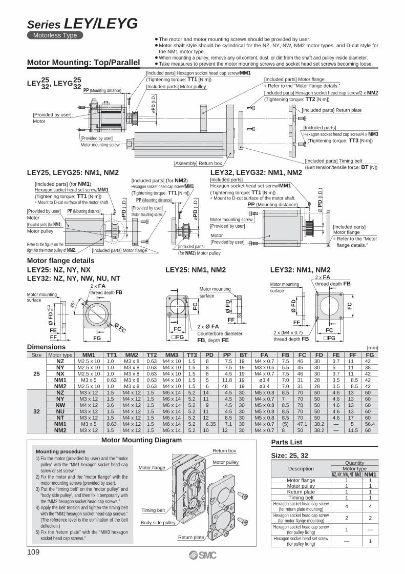
Motor flange
Timing belt
Return box
Motor pulley
Body side pulley
Return plate
[Provided by user]
Motor
[Included parts] (for NM1)
Motor pulley
Refer to the figure on the
right for the motor pulley of NM2. [Included parts] Motor flange[Included parts]
(for NM2) Motor pulley
øP
D (
I.D
.)
PP (Mounting distance)
øP
D (
I.D
.)PP (Mounting distance)
[Provided by user]
Motor mounting screw
[Included parts] (for NM2)
Hexagon socket head cap screw/MM1
(Tightening torque: TT1 [N·m])
[Included parts] (for NM1)
Hexagon socket head set screw/MM1
(Tightening torque: TT1 [N·m])
∗ Mount to D-cut surface of the motor shaft.
Motor flange
∗ Refer to the “Motor
flange details.”
[Included parts]
[Included parts]
Motor
[Provided by user]
Ø P
D (
I.D
.)
Hexagon socket head set screw/MM1
(Tightening torque: TT1 [N·m])∗ Mount to D-cut surface of the motor shaft.
Motor mounting screw
[Provided by user]
PP (Mounting distance)
[Included parts] Return plate
[Provided by user]
Motor mounting screw
[Provided by user]
Motor
PP (Mounting distance)[Included parts] Motor pulley
[Included parts] Hexagon socket head cap screw/MM1
(Tightening torque: TT1 [N·m])
øP
D (
I.D
.) [Included parts] Hexagon socket head cap screw/2 x MM2
(Tightening torque: TT2 [N·m])
[Included parts] Timing belt
(Belt tension/tensile force: BT [N])[Assembly] Return box
[Included parts]
Hexagon socket head cap screw/4 x MM3
(Tightening torque: TT3 [N·m])
[Included parts] Motor flange
∗ Refer to the “Motor flange details.”
LEY25, LEYG25: NM1, NM2 LEY32, LEYG32: NM1, NM2
¡The motor and motor mounting screws should be provided by user.
¡Motor shaft style should be cylindrical for the NZ, NY, NW, NM2 motor types, and D-cut style for
the NM1 motor type.
¡When mounting a pulley, remove any oil content, dust, or dirt from the shaft and pulley inside diameter.
¡Take measures to prevent the motor mounting screws and socket head set screws becoming loose.
LEY , LEYG 2532
2532
Motor fl ange details
[mm]
�FG
FC
FF
Ø F
D
FC
2 x FA
thread depth FB
2 x (M4 x 0.7)
thread depth FB
Motor mounting
surface
LEY32: NM1, NM2
FF
Ø F
D
FC
FC
�FG
Motor mounting
surface
2 x Ø FA
Counterbore diameter
FB, depth FE
LEY25: NM1, NM2
45
°
Ø FC
FGFF
FE
Ø F
D+
0.3
+
0.1
2 x FA
thread depth FBMotor mountingsurface
LEY25: NZ, NY, NX
LEY32: NZ, NY, NW, NU, NT
Dimensions
Motor Mounting: Top/Parallel
Mounting procedure
1) Fix the motor (provided by user) and the “motor
pulley” with the “MM1 hexagon socket head cap
screw or set screw.”
2) Fix the motor and the “motor flange” with the
motor mounting screws (provided by user).
3) Put the “timing belt” on the “motor pulley” and
“body side pulley”, and then fi x it temporarily with
the “MM2 hexagon socket head cap screws.”
4) Apply the belt tension and tighten the timing belt
with the “MM2 hexagon socket head cap screws.”
(The reference level is the elimination of the belt
defl ection.)
5) Fix the “return plate” with the “MM3 hexagon
socket head cap screws.”
Size: 25, 32
Parts ListMotor Mounting Diagram
Size Motor type MM1 TT1 MM2 TT2 MM3 TT3 PD PP BT FA FB FC FD FE FF FG
25
NZ M2.5 x 10 1.0 M3 x 8 0.63 M4 x 10 1.5 8 7.5 19 M4 x 0.7 7.5 46 30 3.7 11 42
NY M2.5 x 10 1.0 M3 x 8 0.63 M4 x 10 1.5 8 7.5 19 M3 x 0.5 5.5 45 30 5 11 38
NX M2.5 x 10 1.0 M3 x 8 0.63 M4 x 10 1.5 8 4.5 19 M4 x 0.7 7.5 46 30 3.7 11 42
NM1 M3 x 5 0.63 M3 x 8 0.63 M4 x 10 1.5 5 11.8 19 ø3.4 7.0 31 28 3.5 8.5 42
NM2 M2.5 x 10 1.0 M3 x 8 0.63 M4 x 10 1.5 6 48 19 ø3.4 7.0 31 28 3.5 8.5 42
32
NZ M3 x 12 1.5 M4 x 12 1.5 M6 x 14 5.2 14 4.5 30 M5 x 0.8 8.5 70 50 4.6 13 60
NY M3 x 12 1.5 M4 x 12 1.5 M6 x 14 5.2 11 4.5 30 M4 x 0.7 7 70 50 4.6 13 60
NW M4 x 12 3.6 M4 x 12 1.5 M6 x 14 5.2 9 4.5 30 M5 x 0.8 8.5 70 50 4.6 13 60
NU M3 x 12 1.5 M4 x 12 1.5 M6 x 14 5.2 11 4.5 30 M5 x 0.8 8.5 70 50 4.6 13 60
NT M3 x 12 1.5 M4 x 12 1.5 M6 x 14 5.2 12 8.5 30 M5 x 0.8 8.5 70 50 4.6 17 60
NM1 M3 x 5 0.63 M4 x 12 1.5 M6 x 14 5.2 6.35 7.1 30 M4 x 0.7 (5) 47.1 38.2 — 5 56.4
NM2 M3 x 12 1.5 M4 x 12 1.5 M6 x 14 5.2 10 12 30 M4 x 0.7 8 50 38.2 — 11.5 60
DescriptionQuantity
Motor typeNZ, NY, NW, NT, NM2 NM1
Motor fl ange 1 1Motor pulley 1 1Return plate 1 1Timing belt 1 1
Hexagon socket head cap screw(for return plate mounting)
4 4
Hexagon socket head cap screw(for motor fl ange mounting)
2 2
Hexagon socket head cap screw(for pulley fi xing)
1 —
Hexagon socket head set screw(for pulley fi xing)
— 1
109
Series LEY/LEYGMotorless Type
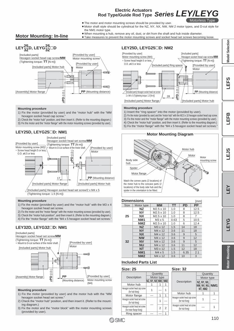
Motor Mounting: In-line
¡The motor and motor mounting screws should be provided by user.
¡Motor shaft style should be cylindrical for the NZ, NY, NX, NW, NM 2 motor types, and D-cut style for
the NM1 motor type.
¡When mounting a hub, remove any oil, dust, or dirt from the shaft and hub inside diameter.
¡Take measures to prevent the motor mounting screws and socket head set screws becoming loose.
[Provided by user]
Motor mounting screw (M4)
Screw head height 5 or less,
O.D. ø6.5 or less[Included parts] Ring spacer
[Included parts]
Hexagon socket head cap screw/MM
(Tightening torque: TT [N·m])
[Provided by user]
Motor
PP (Mounting distance)
[Included parts] Motor hub
øP
D (
I.D
.)
28
[Included parts] Motor flange
[Included parts] Hexagon socket head set screw/
2 x M4 x 5 (Tightening torque: 1.5 [N·m])
[Included parts] Hexagon socket head cap screw/MM
(Tightening torque: TT [N·m])
[Included parts] Motor hub[Provided by user]
Motor
[Provided by user]
Motor mounting screw
PP (Mounting distance)
øP
D (
I.D
.)[Assembly] Motor flange
Motor hub
MotorMotor mounting screwBody side
hub
Spider
Motor flange
Match the convex parts (2 locations) of
the motor hub to the concave parts (2
locations) of the body side hub and the
spider in the orientation to be fitted.
[Assembly] Motor flange
[Included parts] Hexagon socket head set screw/MM
(Tightening torque: TT [N·m]) Mount to D-cut surface of the motor shaft.
[Included parts] Motor hub
[Provided by user]
Motor
[Provided by user]
Motor mounting screw(M4)
PP
(Mounting distance)øP
D (
I.D
.)
17
øP
D (
I.D
.)
[Included parts] Motor flange
[Included parts] Hexagon socket head set screw/2 x M4 x 5
(Tightening torque: 1.5 [N·m])
[Provided by user]
Motor mounting screw (M3) Screw head height 5 or less,O.D. ø6.5 or less
[Included parts] Hexagon socket head set screw/MM
(Tightening torque: TT [N·m]) Mount to D-cut surface of the motor shaft.
[Included parts] Motor hub
[Provided by user]
Motor
PP (Mounting distance)
Mounting procedure
1) Insert the “ring spacer” into the motor (provided by user).
2) Fix the motor (provided by user) and the “motor hub” with the M2.5 x 10 hexagon socket head cap screw.
3) Fix the motor and the “motor fl ange” with the motor mounting screws (provided by user).
4) Check the “motor hub” position, and then insert it. (Refer to the mounting diagram.)
5) Fix the “motor fl ange” with the “M4 x 5 hexagon socket head set screws.”
LEY25D, LEYG25�D: NM2
Size: 32
Description
Quantity
Motor type
NZ, NY, NX,NW, NV, NU,
NT, NM2NM1
Motor hub 1 1
Hexagon socket head cap screw(for hub fi xing)
1 —
Hexagon socket head set screw(for hub fi xing)
— 1
Size Motor type MM TT PD PP
25
NZ M2.5 x 10 1.0 8 12.5
NY M2.5 x 10 1.0 8 12.5
NX M2.5 x 10 1.0 8 7
NM1 M3 x 5 0.63 5 10.5
NM2 M2.5 x 10 1.0 6 12.4
32
NZ M3 x 12 1.5 14 18
NY M4 x 12 3.6 11 18
NX M4 x 12 3.6 9 5
NW M4 x 12 3.6 9 12
NV M4 x 12 3.6 9 5
NU M4 x 12 3.6 11 12
NT M3 x 12 1.5 12 18
NM1 M4 x 5 1.5 6.35 2.1
NM2 M4 x 12 3.6 10 3
[mm]Dimensions
Mounting procedure
1) Fix the motor (provided by user) and the “motor hub” with the “MM
hexagon socket head cap screw.”
2) Check the “motor hub” position, and then insert it. (Refer to the mounting diagram.)
3) Fix the motor and the “motor fl ange” with the motor mounting screws (provided by user).
LEY25D, LEYG25�D: NM1
Mounting procedure
1) Fix the motor (provided by user) and the “motor hub” with the M3 x 4
hexagon socket head set screw.
2) Fix the motor and the “motor fl ange” with the motor mounting screws (provided by user).
3) Check the “motor hub position”, and then insert it. (Refer to the mounting diagram.)
4) Fix the “motor fl ange” with the “M4 x 5 hexagon socket head set screws.”
LEY32D, LEYG32�D: NM1
Mounting procedure
1) Fix the motor (provided by user) and the motor hub with the “MM
hexagon socket head set screw.”
2) Check the “motor hub” position, and then insert it. (Refer to the mount-
ing diagram.)
3) Fix the motor and the “motor block” with the motor mounting screws
(provided by user).
Description
Quantity
Motor type
NZ, NY, NX NM1 NM2Motor hub 1 1 1
Hexagon socket head cap screw(for hub fi xing)
1 — 1
Motor fl ange — 1 1
Hexagon socket head set screw(for hub fi xing)
—
1 —
Hexagon socket head set screw(for motor fl ange fi xing)
2 2
Ring spacer — — 1
Size: 25
Included Parts List
LEY D, LEYG �D2532
2532
Motor Mounting Diagram
110
Electric ActuatorsRod Type/Guide Rod Type Series LEY/LEYG
Motorless Type
LE
FS
LE
FB
LE
JS
LE
YL
EY
GM
od
el
Se
lec
tio
nM
oto
r M
ou
nti
ng
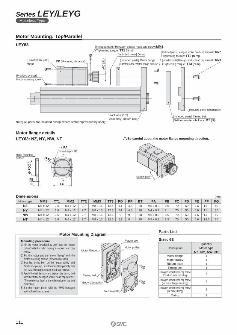
Motor flange
Timing belt
Return box
Motor pulley
Body side pulley
Return plate
4 x FA
thread depth FB
FGFF
FE
Ø F
D+
0.3
+
0.1
Ø FC
Motor mountingsurface
Narrow pitch
[Provided by user]
Motor
[Provided by user]
Motor mounting screw
PP (Mounting distance)
øP
D (
I.D
.)
[Included parts] Hexagon socket head cap screw/MM1
(Tightening torque: TT1 [N·m])[Included parts] Hexagon socket head cap screw/4 x MM2
(Tightening torque: TT2 [N·m])
Front view (1:2)
[Assembly] Return box[Included parts] Timing belt
(Belt tension/tensile force: BT [N])
[Included parts] Return plate
[Included parts] Hexagon socket head cap screw/4 x MM3
(Tightening torque: TT3 [N·m])
[Included parts] Motor flange
Refer to the “Motor flange details.”
[Included parts] O-ring
Motor Mounting: Top/Parallel
LEY63
Description
Quantity
Motor type
NZ, NY, NW, NTMotor fl ange 1
Motor pulley 1
Return plate 1
Timing belt 1
Hexagon socket head cap screw(for return plate mounting)
4
Hexagon socket head cap screw(for motor fl ange mounting)
4
Hexagon socket head cap screw(for pulley fi xing)
1
O-ring 1
Dimensions
Size: 63
[mm]
Mounting procedure
1) Fix the motor (provided by user) and the “motor
pulley” with the “MM1 hexagon socket head cap
screw.”
2) Fix the motor and the “motor flange” with the
motor mounting screws (provided by user).
3) Put the “timing belt” on the “motor pulley” and
“body side pulley”, and then fi x it temporarily with
the “MM2 hexagon socket head cap screws.”
4) Apply the belt tension and tighten the timing belt
with the “MM2 hexagon socket head cap screws.”
(The reference level is the elimination of the belt
defl ection.)
5) Fix the “return plate” with the “MM3 hexagon
socket head cap screws.”
Motor fl ange details
LEY63: NZ, NY, NW, NT
Parts ListMotor Mounting Diagram
Be careful about the motor fl ange mounting direction.
Note) All parts are included except where stated “(provided by user)”
Motor type MM1 TT1 MM2 TT2 MM3 TT3 PD PP BT FA FB FC FD FE FF FG
NZ M4 x 12 3.6 M4 x 12 2.7 M8 x 16 12.5 14 4.5 98 M5 x 0.8 8.5 70 50 4.6 11 60
NY M4 x 12 3.6 M4 x 12 2.7 M8 x 16 12.5 14 4.5 98 M4 x 0.7 8 70 50 4.6 11 60
NW M4 x 12 3.6 M4 x 12 2.7 M8 x 16 12.5 9 9 98 M5 x 0.8 8.5 70 50 4.6 11 60
NT M4 x 12 3.6 M4 x 12 2.7 M8 x 16 12.5 12 8 98 M5 x 0.8 8.5 70 50 4.6 14.5 60
111
Series LEY/LEYGMotorless Type
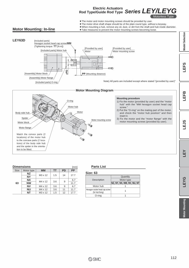
Motor mounting screw
Motor
Motor hub
O-ring
Body side hub
Spider
Motor block
Motor flange
Match the convex parts (2
locations) of the motor hub
to the concave parts (2 loca-
tions) of the body side hub
and the spider in the orienta-
tion to be fitted.
Note) All parts are included except where stated “(provided by user)”[Included parts] O-ring
[Assembly] Motor flange
[Included parts] Motor hub
[Included parts] Hexagon socket head cap screw/MM
(Tightening torque: TT [N·m])[Provided by user]
Motor mounting screw
[Provided by user]
Motor
PP (Mounting distance)øP
D
[Assembly] Motor block
Description
Quantity
Motor type
NZ, NY, NX, NW, NV, NU, NTMotor hub 1
Hexagon socket head cap screw(for hub fi xing)
1
O-ring 1
Size Motor type MM TT PD PP
63
NZM3 x 12 1.5 14 17.7
NYNX
M4 x 12 3.6 96.7
NW 11.7
NV M4 x 12 3.6 9 6.7
NU M4 x 12 3.6 11 11.7
NT M3 x 12 1.5 12 17.7
Motor Mounting: In-line
LEY63D
Dimensions [mm]
Mounting procedure
1) Fix the motor (provided by user) and the “motor
hub” with the “MM hexagon socket head cap
screw.”
2) Put the “O-ring” on the mating part of the motor,
and check the “motor hub position” and then
insert it.
3) Fix the motor and the “motor fl ange” with the
motor mounting screws (provided by user).
Size: 63
Parts List
Motor Mounting Diagram
¡The motor and motor mounting screws should be provided by user.
¡The motor drive shaft shape should be of the plain round type, without a keyway.
¡When mounting a hub, remove any oil, dust, or dirt from the shaft and hub inside diameter.
¡Take measures to prevent the motor mounting screws becoming loose.
112
Electric ActuatorsRod Type/Guide Rod Type Series LEY/LEYG
Motorless Type
LE
FS
LE
FB
LE
JS
LE
YL
EY
GM
od
el
Se
lec
tio
nM
oto
r M
ou
nti
ng
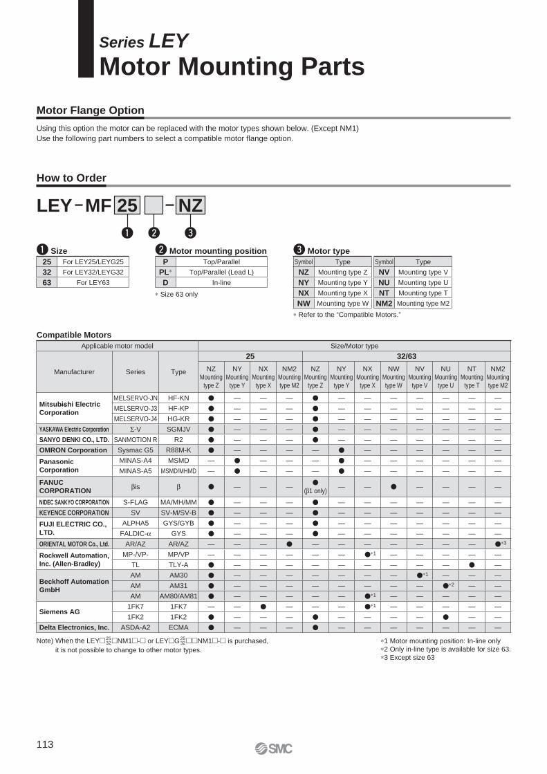
Series LEY
Motor Mounting Parts
Motor Flange Option
Using this option the motor can be replaced with the motor types shown below. (Except NM1)
Use the following part numbers to select a compatible motor fl ange option.
How to Order
q Size
LEY MF NZ25
w Motor mounting position
Compatible Motors
q w e
25 For LEY25/LEYG25
32 For LEY32/LEYG32
63 For LEY63
P Top/Parallel
PL∗ Top/Parallel (Lead L)
D In-line
∗ Size 63 only
Note) When the LEY�25 32�NM1�-� or LEY�G25
32��NM1�-� is purchased,
it is not possible to change to other motor types.
Applicable motor model Size/Motor type
Manufacturer Series Type
25 32/63
NZ
Mounting
type Z
NY
Mounting
type Y
NX
Mounting
type X
NM2
Mounting
type M2
NZ
Mounting
type Z
NY
Mounting
type Y
NX
Mounting
type X
NW
Mounting
type W
NV
Mounting
type V
NU
Mounting
type U
NT
Mounting
type T
NM2
Mounting
type M2
Mitsubishi Electric
Corporation
MELSERVO-JN HF-KN � — — — � — — — — — — —
MELSERVO-J3 HF-KP � — — — � — — — — — — —
MELSERVO-J4 HG-KR � — — — � — — — — — — —
YASKAWA Electric Corporation Σ-V SGMJV � — — — � — — — — — — —
SANYO DENKI CO., LTD. SANMOTION R R2 � — — — � — — — — — — —
OMRON Corporation Sysmac G5 R88M-K � — — — — � — — — — — —
Panasonic
Corporation
MINAS-A4 MSMD — � — — — � — — — — — —
MINAS-A5 MSMD/MHMD — � — — — � — — — — — —
FANUC
CORPORATIONβis β � — — —
�(β1 only)
— — � — — — —
NIDEC SANKYO CORPORATION S-FLAG MA/MH/MM � — — — � — — — — — — —
KEYENCE CORPORATION SV SV-M/SV-B � — — — � — — — — — — —
FUJI ELECTRIC CO.,
LTD.
ALPHA5 GYS/GYB � — — — � — — — — — — —
FALDIC-α GYS � — — — � — — — — — — —
ORIENTAL MOTOR Co., Ltd. AR/AZ AR/AZ — — — � — — — — — — — �∗3
Rockwell Automation,
Inc. (Allen-Bradley)
MP-/VP- MP/VP — — — — — — �∗1 — — — — —
TL TLY-A � — — — — — — — — — � —
Beckhoff Automation
GmbH
AM AM30 � — — — — — — — �∗1 — — —
AM AM31 � — — — — — — — — �∗2 — —
AM AM80/AM81 � — — — — — �∗1 — — — — —
Siemens AG1FK7 1FK7 — — � — — — �∗1 — — — — —
1FK2 1FK2 � — — — � — — — — � — —
Delta Electronics, Inc. ASDA-A2 ECMA � — — — � — — — — — — —
∗ Refer to the “Compatible Motors.”
e Motor type
Symbol Type
NZ Mounting type Z
NY Mounting type Y
NX Mounting type X
NW Mounting type W
Symbol Type
NV Mounting type V
NU Mounting type U
NT Mounting type T
NM2 Mounting type M2
∗1 Motor mounting position: In-line only
∗2 Only in-line type is available for size 63.
∗3 Except size 63
—
113
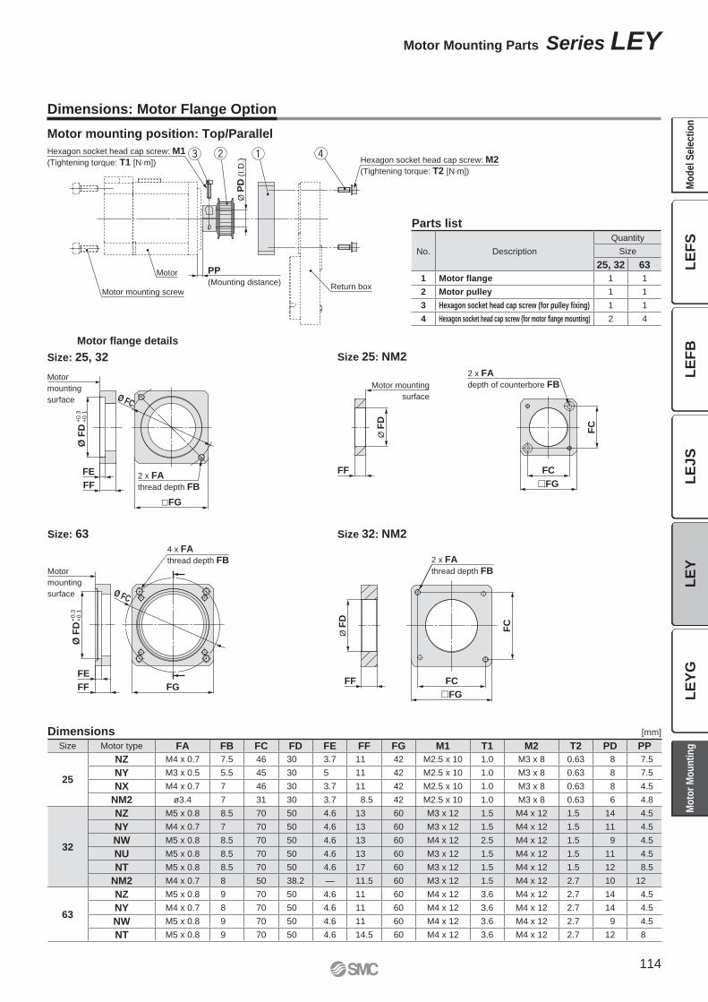
Motor mounting screw
Motor
Hexagon socket head cap screw: M1
(Tightening torque: T1 [N·m])
Return box
PP
(Mounting distance)
Ø P
D (
I.D
.)
qwe rHexagon socket head cap screw: M2
(Tightening torque: T2 [N·m])
2 x FA
thread depth FB
Ø FC
Ø F
D
FF
FE
�FG
Motor
mounting
surface
+0.3
+0.1
Ø F
D+
0.3
+0.1
4 x FA
thread depth FBMotor
mounting
surface
FE
FGFF
Ø FC
Size 25: NM2
Size 32: NM2
2 x FA
depth of counterbore FBMotor mounting
surface
Ø F
D
FC
FF FC
�FG
Ø F
D
FF
�FG
FC
FC
2 x FA
thread depth FB
Dimensions: Motor Flange Option
Motor mounting position: Top/Parallel
Motor fl ange details
Size: 25, 32
Size: 63
Parts list
No. Description
Quantity
Size
25, 32 63
1 Motor flange 1 1
2 Motor pulley 1 1
3 Hexagon socket head cap screw (for pulley fixing) 1 1
4 Hexagon socket head cap screw (for motor flange mounting) 2 4
Size Motor type FA FB FC FD FE FF FG M1 T1 M2 T2 PD PP
25
NZ M4 x 0.7 7.5 46 30 3.7 11 42 M2.5 x 10 1.0 M3 x 8 0.63 8 7.5
NY M3 x 0.5 5.5 45 30 5 11 42 M2.5 x 10 1.0 M3 x 8 0.63 8 7.5
NX M4 x 0.7 7 46 30 3.7 11 42 M2.5 x 10 1.0 M3 x 8 0.63 8 4.5
NM2 ø3.4 7 31 30 3.7 8.5 42 M2.5 x 10 1.0 M3 x 8 0.63 6 4.8
32
NZ M5 x 0.8 8.5 70 50 4.6 13 60 M3 x 12 1.5 M4 x 12 1.5 14 4.5
NY M4 x 0.7 7 70 50 4.6 13 60 M3 x 12 1.5 M4 x 12 1.5 11 4.5
NW M5 x 0.8 8.5 70 50 4.6 13 60 M4 x 12 2.5 M4 x 12 1.5 9 4.5
NU M5 x 0.8 8.5 70 50 4.6 13 60 M3 x 12 1.5 M4 x 12 1.5 11 4.5
NT M5 x 0.8 8.5 70 50 4.6 17 60 M3 x 12 1.5 M4 x 12 1.5 12 8.5
NM2 M4 x 0.7 8 50 38.2 — 11.5 60 M3 x 12 1.5 M4 x 12 2.7 10 12
63
NZ M5 x 0.8 9 70 50 4.6 11 60 M4 x 12 3.6 M4 x 12 2.7 14 4.5
NY M4 x 0.7 8 70 50 4.6 11 60 M4 x 12 3.6 M4 x 12 2.7 14 4.5
NW M5 x 0.8 9 70 50 4.6 11 60 M4 x 12 3.6 M4 x 12 2.7 9 4.5
NT M5 x 0.8 9 70 50 4.6 14.5 60 M4 x 12 3.6 M4 x 12 2.7 12 8
Dimensions [mm]
114
Motor Mounting Parts Series LEY
LE
FS
LE
FB
LE
JS
LE
YL
EY
GM
od
el
Se
lec
tio
nM
oto
r M
ou
nti
ng
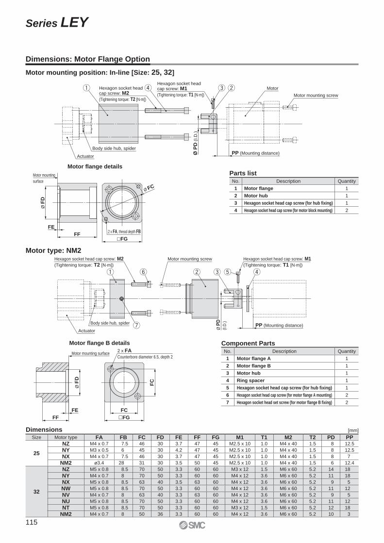
Hexagon socket head cap screw: M2
(Tightening torque: T2 [N·m])
q rHexagon socket head cap screw: M1
(Tightening torque: T1 [N·m])
e w
Ø P
D (
I.D
.)
PP (Mounting distance)Body side hub, spider
Actuator
Motor
Motor mounting screw
2 x FA, thread depth FB
�FG
Ø FC
FF
Ø F
D
Motor mounting
surface
FE
Dimensions: Motor Flange Option
Motor mounting position: In-line [Size: 25, 32]
Motor fl ange details
Parts listNo. Description Quantity
1 Motor flange 1
2 Motor hub 1
3 Hexagon socket head cap screw (for hub fixing) 1
4 Hexagon socket head cap screw (for motor block mounting) 2
y w re tq
u
Hexagon socket head cap screw: M2
(Tightening torque: T2 [N·m])
Motor mounting screw Hexagon socket head cap screw: M1
(Tightening torque: T1 [N·m])
PP (Mounting distance)Actuator
Body side hub, spider
Ø P
D
(I.D
.)
Motor type: NM2
Motor fl ange B details Component PartsNo. Description Quantity
1 Motor flange A 1
2 Motor flange B 1
3 Motor hub 1
4 Ring spacer 1
5 Hexagon socket head cap screw (for hub fixing) 1
6 Hexagon socket head cap screw (for motor flange A mounting) 2
7 Hexagon socket head set screw (for motor flange B fixing) 2
Size Motor type FA FB FC FD FE FF FG M1 T1 M2 T2 PD PP
25
NZ M4 x 0.7 7.5 46 30 3.7 47 45 M2.5 x 10 1.0 M4 x 40 1.5 8 12.5
NY M3 x 0.5 6 45 30 4.2 47 45 M2.5 x 10 1.0 M4 x 40 1.5 8 12.5
NX M4 x 0.7 7.5 46 30 3.7 47 45 M2.5 x 10 1.0 M4 x 40 1.5 8 7
NM2 ø3.4 28 31 30 3.5 50 45 M2.5 x 10 1.0 M4 x 40 1.5 6 12.4
32
NZ M5 x 0.8 8.5 70 50 3.3 60 60 M3 x 12 1.5 M6 x 60 5.2 14 18
NY M4 x 0.7 8 70 50 3.3 60 60 M4 x 12 3.6 M6 x 60 5.2 11 18
NX M5 x 0.8 8.5 63 40 3.5 63 60 M4 x 12 3.6 M6 x 60 5.2 9 5
NW M5 x 0.8 8.5 70 50 3.3 60 60 M4 x 12 3.6 M6 x 60 5.2 11 12
NV M4 x 0.7 8 63 40 3.3 63 60 M4 x 12 3.6 M6 x 60 5.2 9 5
NU M5 x 0.8 8.5 70 50 3.3 60 60 M4 x 12 3.6 M6 x 60 5.2 11 12
NT M5 x 0.8 8.5 70 50 3.3 60 60 M3 x 12 1.5 M6 x 60 5.2 12 18
NM2 M4 x 0.7 8 50 36 3.3 60 60 M4 x 12 3.6 M6 x 60 5.2 10 3
Dimensions [mm]
�FG
FC
FC
2 x FA
Counterbore diameter 6.5, depth 2Motor mounting surface
Ø F
D
FE
FF
115
Series LEY
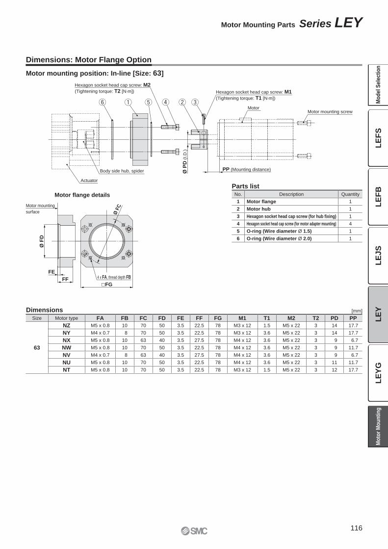
Hexagon socket head cap screw: M2
(Tightening torque: T2 [N·m]) Hexagon socket head cap screw: M1
(Tightening torque: T1 [N·m])q w erty
Motor
Actuator
Body side hub, spider Ø P
D (
I.D
.)
PP (Mounting distance)
Motor mounting screw
FE4 x FA, thread depth FB
�FG
Ø F
D
FF
Ø F
CMotor mounting
surface
Dimensions: Motor Flange Option
Motor mounting position: In-line [Size: 63]
Motor fl ange details
Parts listNo. Description Quantity
1 Motor flange 1
2 Motor hub 1
3 Hexagon socket head cap screw (for hub fixing) 1
4 Hexagon socket head cap screw (for motor adapter mounting) 4
5 O-ring (Wire diameter Ø 1.5) 1
6 O-ring (Wire diameter Ø 2.0) 1
Dimensions [mm]
Size Motor type FA FB FC FD FE FF FG M1 T1 M2 T2 PD PP
63
NZ M5 x 0.8 10 70 50 3.5 22.5 78 M3 x 12 1.5 M5 x 22 3 14 17.7
NY M4 x 0.7 8 70 50 3.5 22.5 78 M3 x 12 3.6 M5 x 22 3 14 17.7
NX M5 x 0.8 10 63 40 3.5 27.5 78 M4 x 12 3.6 M5 x 22 3 9 6.7
NW M5 x 0.8 10 70 50 3.5 22.5 78 M4 x 12 3.6 M5 x 22 3 9 11.7
NV M4 x 0.7 8 63 40 3.5 27.5 78 M4 x 12 3.6 M5 x 22 3 9 6.7
NU M5 x 0.8 10 70 50 3.5 22.5 78 M4 x 12 3.6 M5 x 22 3 11 11.7
NT M5 x 0.8 10 70 50 3.5 22.5 78 M3 x 12 1.5 M5 x 22 3 12 17.7
116
Motor Mounting Parts Series LEY
LE
FS
LE
FB
LE
JS
LE
YL
EY
GM
od
el
Se
lec
tio
nM
oto
r M
ou
nti
ng
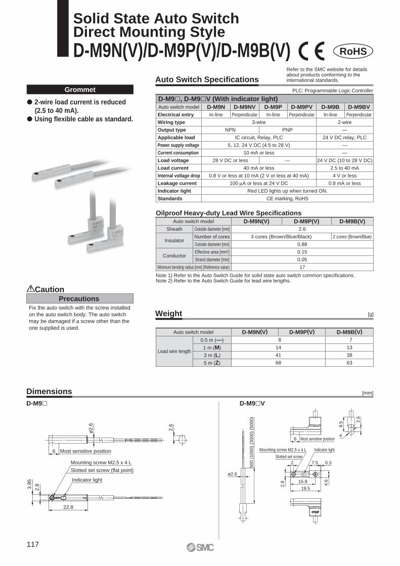
Most sensitive position
ø2.6
2.6
3.9
5
2.8
6
22.8
Mounting screw M2.5 x 4 L
Slotted set screw (flat point)
Indicator light
19.5
15.9
7.5
9.5
4
2.6
0.3
ø2.6
Indicator light
Slotted set screw
2
Most sensitive position6
2.8 4.6
50
0 (
10
00
) (3
00
0)
(50
00
)
Mounting screw M2.5 x 4 L
Auto Switch Specifi cations
Weight
Dimensions
Precautions
Caution
Fix the auto switch with the screw installed
on the auto switch body. The auto switch
may be damaged if a screw other than the
one supplied is used.
[g]
Grommet
Note 1) Refer to the Auto Switch Guide for solid state auto switch common specifi cations.Note 2) Refer to the Auto Switch Guide for lead wire lengths.
D-M9� D-M9�V
� 2-wire load current is reduced
(2.5 to 40 mA).
� Using fl exible cable as standard.
[mm]
Oilproof Heavy-duty Lead Wire Specifi cations
RoHS
Solid State Auto SwitchDirect Mounting Style
D-M9N(V)/D-M9P(V)/D-M9B(V)
PLC: Programmable Logic Controller
Refer to the SMC website for details about products conforming to the international standards.
D-M9�, D-M9�V (With indicator light)Auto switch model D-M9N D-M9NV D-M9P D-M9PV D-M9B D-M9BV
Electrical entry In-line Perpendicular In-line Perpendicular In-line Perpendicular
Wiring type 3-wire 2-wire
Output type NPN PNP —
Applicable load IC circuit, Relay, PLC 24 V DC relay, PLC
Power supply voltage 5, 12, 24 V DC (4.5 to 28 V) —
Current consumption 10 mA or less —
Load voltage 28 V DC or less — 24 V DC (10 to 28 V DC)
Load current 40 mA or less 2.5 to 40 mA
Internal voltage drop 0.8 V or less at 10 mA (2 V or less at 40 mA) 4 V or less
Leakage current 100 μA or less at 24 V DC 0.8 mA or less
Indicator light Red LED lights up when turned ON.
Standards CE marking, RoHS
Auto switch model D-M9N(V) D-M9P(V) D-M9B(V)
Lead wire length
0.5 m (—) 8 7
1 m (M) 14 13
3 m (L) 41 38
5 m (Z) 68 63
Auto switch model D-M9N(V) D-M9P(V) D-M9B(V)
Sheath Outside diameter [mm] 2.6
InsulatorNumber of cores 3 cores (Brown/Blue/Black) 2 cores (Brown/Blue)
Outside diameter [mm] 0.88
ConductorEffective area [mm2] 0.15
Strand diameter [mm] 0.05
Minimum bending radius [mm] (Reference value) 17
117
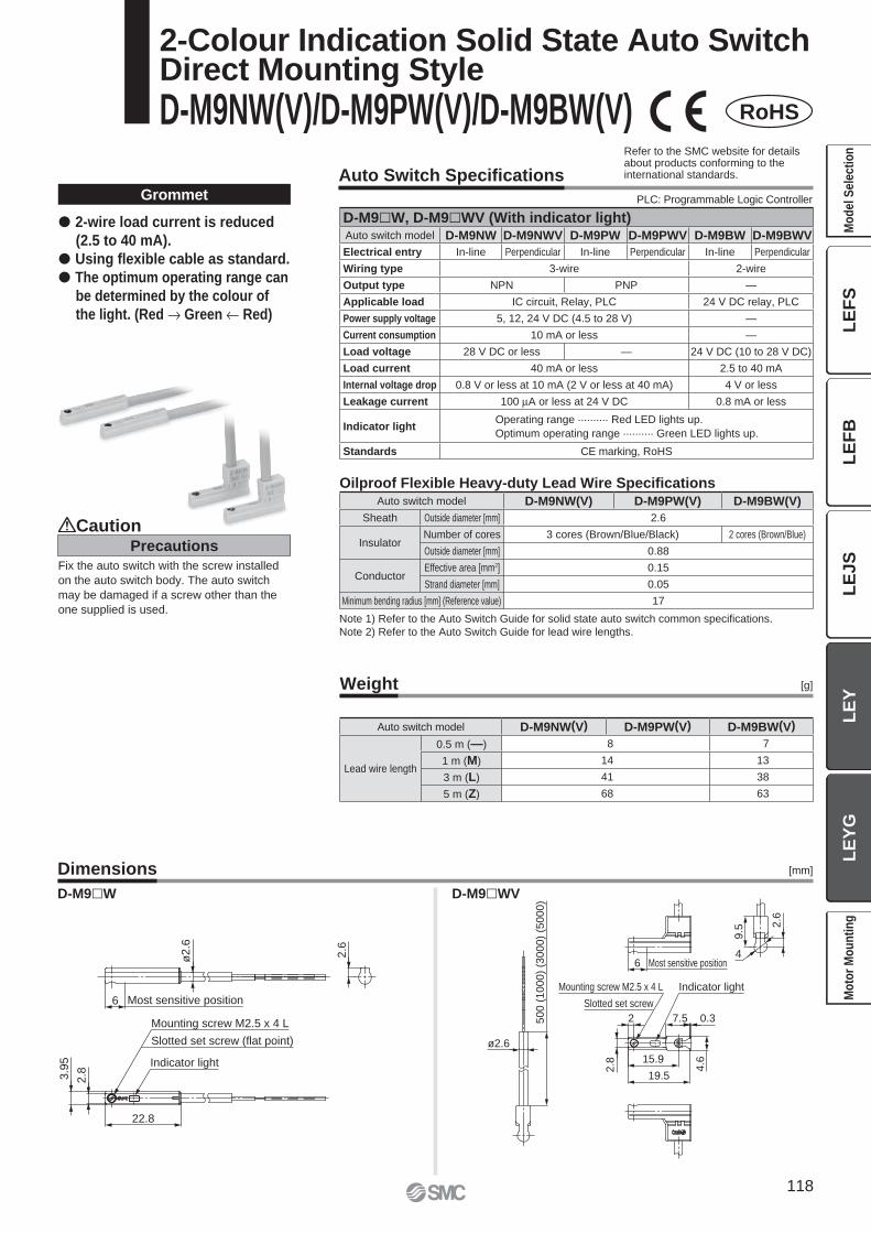
6 Most sensitive position
2.6
ø2.6
22.8
Indicator light
3.9
5
2.8
Slotted set screw (flat point)
Mounting screw M2.5 x 4 L 500 (
1000)
(3000)
(5000)
Indicator light
ø2.6
4.6
0.37.5
Mounting screw M2.5 x 4 L
Slotted set screw
2.8
9.5
2.6
4Most sensitive position6
19.5
15.9
2
Auto Switch Specifi cations
Weight
Dimensions
[g]
[mm]
Grommet
Note 1) Refer to the Auto Switch Guide for solid state auto switch common specifi cations.
Note 2) Refer to the Auto Switch Guide for lead wire lengths.
� 2-wire load current is reduced
(2.5 to 40 mA).
� Using fl exible cable as standard.
� The optimum operating range can
be determined by the colour of
the light. (Red → Green ← Red)
D-M9�W D-M9�WV
RoHS
Oilproof Flexible Heavy-duty Lead Wire Specifi cations
2-Colour Indication Solid State Auto SwitchDirect Mounting Style
D-M9NW(V)/D-M9PW(V)/D-M9BW(V)
Precautions
Caution
Fix the auto switch with the screw installed
on the auto switch body. The auto switch
may be damaged if a screw other than the
one supplied is used.
Refer to the SMC website for details about products conforming to the international standards.
PLC: Programmable Logic Controller
D-M9�W, D-M9�WV (With indicator light)Auto switch model D-M9NW D-M9NWV D-M9PW D-M9PWV D-M9BW D-M9BWV
Electrical entry In-line Perpendicular In-line Perpendicular In-line Perpendicular
Wiring type 3-wire 2-wire
Output type NPN PNP —
Applicable load IC circuit, Relay, PLC 24 V DC relay, PLC
Power supply voltage 5, 12, 24 V DC (4.5 to 28 V) —
Current consumption 10 mA or less —
Load voltage 28 V DC or less — 24 V DC (10 to 28 V DC)
Load current 40 mA or less 2.5 to 40 mA
Internal voltage drop 0.8 V or less at 10 mA (2 V or less at 40 mA) 4 V or less
Leakage current 100 μA or less at 24 V DC 0.8 mA or less
Indicator lightOperating range .......... Red LED lights up.
Optimum operating range .......... Green LED lights up.
Standards CE marking, RoHS
Auto switch model D-M9NW(V) D-M9PW(V) D-M9BW(V)
Sheath Outside diameter [mm] 2.6
InsulatorNumber of cores 3 cores (Brown/Blue/Black) 2 cores (Brown/Blue)
Outside diameter [mm] 0.88
ConductorEffective area [mm2] 0.15
Strand diameter [mm] 0.05
Minimum bending radius [mm] (Reference value) 17
Auto switch model D-M9NW(V) D-M9PW(V) D-M9BW(V)
Lead wire length
0.5 m (—) 8 7
1 m (M) 14 13
3 m (L) 41 38
5 m (Z) 68 63
118
LE
FS
LE
FB
LE
JS
LE
YL
EY
GM
od
el
Se
lec
tio
nM
oto
r M
ou
nti
ng
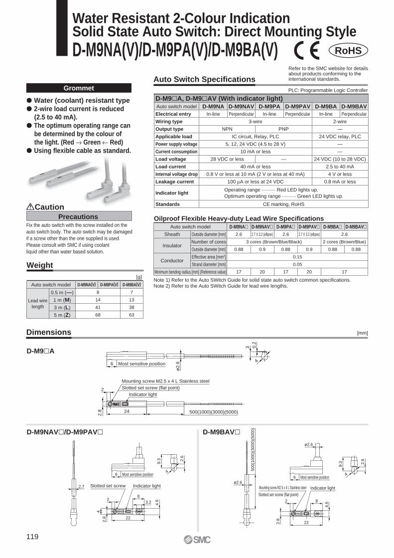
RoHS
Water Resistant 2-Colour IndicationSolid State Auto Switch: Direct Mounting Style
D-M9NA(V)/D-M9PA(V)/D-M9BA(V)
Indicator light
Slotted set screw (flat point)
Mounting screw M2.5 x 4 L Stainless steel
2
2.8
0.2
3
24 500(1000)(3000)(5000)
ø2
.66 Most sensitive position4
Auto Switch Specifi cations
Weight
Dimensions
[g]
[mm]
Grommet
Note 1) Refer to the Auto SWitch Guide for solid state auto switch common specifi cations.
Note 2) Refer to the Auto SWitch Guide for lead wire lengths.
� Water (coolant) resistant type
� 2-wire load current is reduced
(2.5 to 40 mA).
� The optimum operating range can
be determined by the colour of
the light. (Red → Green ← Red)
� Using fl exible cable as standard.
D-M9�A
D-M9NAV�/D-M9PAV� D-M9BAV�
Oilproof Flexible Heavy-duty Lead Wire Specifi cationsPrecautions
Caution
Fix the auto switch with the screw installed on the
auto switch body. The auto switch may be damaged
if a screw other than the one supplied is used.
Please consult with SMC if using coolant
liquid other than water based solution.
Refer to the SMC website for details about products conforming to the international standards.
PLC: Programmable Logic Controller
D-M9�A, D-M9�AV (With indicator light)Auto switch model D-M9NA D-M9NAV D-M9PA D-M9PAV D-M9BA D-M9BAV
Electrical entry In-line Perpendicular In-line Perpendicular In-line Perpendicular
Wiring type 3-wire 2-wire
Output type NPN PNP —
Applicable load IC circuit, Relay, PLC 24 VDC relay, PLC
Power supply voltage 5, 12, 24 VDC (4.5 to 28 V) —
Current consumption 10 mA or less —
Load voltage 28 VDC or less — 24 VDC (10 to 28 VDC)
Load current 40 mA or less 2.5 to 40 mA
Internal voltage drop 0.8 V or less at 10 mA (2 V or less at 40 mA) 4 V or less
Leakage current 100 μA or less at 24 VDC 0.8 mA or less
Indicator lightOperating range .......... Red LED lights up.
Optimum operating range .......... Green LED lights up.
Standards CE marking, RoHS
Auto switch model D-M9NA� D-M9NAV� D-M9PA� D-M9PAV� D-M9BA� D-M9BAV�Sheath Outside diameter [mm] 2.6 2.7 X 3.2 (ellipse) 2.6 2.7 X 3.2 (ellipse) 2.6
InsulatorNumber of cores 3 cores (Brown/Blue/Black) 2 cores (Brown/Blue)
Outside diameter [mm] 0.88 0.9 0.88 0.9 0.88 0.88
ConductorEffective area [mm2] 0.15
Strand diameter [mm] 0.05
Minimum bending radius [mm] (Reference value) 17 20 17 20 17
Auto switch model D-M9NA(V) D-M9PA(V) D-M9BA(V)
Lead wire
length
0.5 m (—) 8 7
1 m (M) 14 13
3 m (L) 41 38
5 m (Z) 68 63
2
4
2.8 22
8
3.2 4.6
9.3
44
2.6
6
2.7
2
2.8 22
8
4.6
ø2.6
9.3 2
.6
6
ø2.6
500(1
000)(
3000)(
5000)
SMCSMC
Indicator lightSlotted set screw
Most sensitive position
Indicator light
Slotted set screw (flat point)
Mounting screw M2.5 x 4 L Stainless steel
Most sensitive position
119
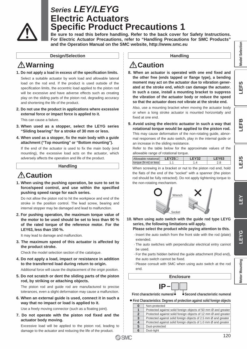
Wrench
Socket
Design/Selection
Warning1. Do not apply a load in excess of the specifi cation limits.
Select a suitable actuator by work load and allowable lateral
load on the rod end. If the product is used outside of the
specifi cation limits, the eccentric load applied to the piston rod
will be excessive and have adverse effects such as creating
play on the sliding parts of the piston rod, degrading accuracy
and shortening the life of the product.
2. Do not use the product in applications where excessive
external force or impact force is applied to it.
This can cause a failure.
3. When used as a stopper, select the LEYG series
“Sliding bearing” for a stroke of 30 mm or less.
4. When used as a stopper, fi x the main body with a guide
attachment (“Top mounting” or “Bottom mounting”).
If the end of the actuator is used to fi x the main body (end
mounting), the excessive load acts on the actuator, which
adversely affects the operation and life of the product.
Handling
Caution1. When using the pushing operation, be sure to set to
force/speed control, and use within the specifi ed
pushing speed range for each series.
Do not allow the piston rod to hit the workpiece and end of the
stroke in the position control. The lead screw, bearing and
internal stopper may be damaged and lead to malfunction.
2. For pushing operation, the maximum torque value of
the motor to be used should be set to less than 90 %
of the rated torque of the reference motor. For the
LEY63, less than 150 %.
It may lead to damage and malfunction.
3. The maximum speed of this actuator is affected by
the product stroke.
Check the model selection section of the catalogue.
4. Do not apply a load, impact or resistance in addition
to the transferred load during return to origin.
Additional force will cause the displacement of the origin position.
5. Do not scratch or dent the sliding parts of the piston
rod, by striking or attaching objects.
The piston rod and guide rod are manufactured to precise
tolerances, even a slight deformation may cause a malfunction.
6. When an external guide is used, connect it in such a
way that no impact or load is applied to it.
Use a freely moving connector (such as a fl oating joint).
7. Do not operate with the piston rod fi xed and the
actuator body moving.
Excessive load will be applied to the piston rod, leading to
damage to the actuator and reducing the life of the product.
Handling
Caution8. When an actuator is operated with one end fi xed and
the other free (ends tapped or fl ange type), a bending
moment may act on the actuator due to vibration gener-
ated at the stroke end, which can damage the actuator.
In such a case, install a mounting bracket to suppress
the vibration of the actuator body or reduce the speed
so that the actuator does not vibrate at the stroke end.
Also, use a mounting bracket when moving the actuator body
or when a long stroke actuator is mounted horizontally and
fi xed at one end.
9. Avoid using the electric actuator in such a way that
rotational torque would be applied to the piston rod.
This may cause deformation of the non-rotating guide, abnor-
mal responses of the auto switch, play in the internal guide or
an increase in the sliding resistance.
Refer to the table below for the approximate values of the
allowable range of rotational torque.
When screwing in a bracket or nut to the piston rod end, hold
the fl ats of the end of the “socket” with a spanner (the piston
rod should be fully retracted). Do not apply tightening torque to
the non-rotating mechanism.
10. When using auto switch with the guide rod type LEYG
series, the following limitations will apply.
Please select the product while paying attention to this.
· Insert the auto switch from the front side with the rod (plate)
extended.
· The auto switches with perpendicular electrical entry cannot
be used.
· For the parts hidden behind the guide attachment (Rod end),
the auto switch cannot be fi xed.
· Please consult with SMC when using auto switch at the rod
end.
Enclosure
¡First Characteristics: Degrees of protection against solid foreign objects
IPFirst characteristic numeral Second characteristic numeral
Series LEY/LEYG Electric ActuatorsSpecifi c Product Precautions 1Be sure to read this before handling. Refer to the back cover for Safety Instructions. For Electric Actuator Precautions, refer to “Handling Precautions for SMC Products” and the Operation Manual on the SMC website, http://www.smc.eu
0 Non-protected
1 Protected against solid foreign objects of 50 mm Ø and greater
2 Protected against solid foreign objects of 12 mm Ø and greater
3 Protected against solid foreign objects of 2.5 mm Ø and greater
4 Protected against solid foreign objects of 1.0 mm Ø and greater
5 Dust-protected
6 Dust-tight
Allowable rotational
torque [N·m] or less
LEY25� LEY32 LEY631.1 1.4 2.8
120
LE
FS
LE
FB
LE
JS
LE
YL
EY
GM
od
el
Se
lec
tio
nM
oto
r M
ou
nti
ng
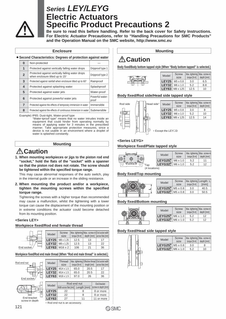
End socket
Rod end nut
End socket
End bracketscrew-in depth
Tap
(4 locations)
L
Rod side Head side∗
Body fi xed/Body bottom tapped style (When “Body bottom tapped” is selected.)
Body fi xed/Rod side/Head side tapped style
Mounting
Caution
∗ Except the LEY�D
Workpiece fi xed/Rod end male thread (When “Rod end male thread” is selected.)
∗ Rod end nut is an accessory.
Mounting
Caution1. When mounting workpieces or jigs to the piston rod end
“socket,” hold the fl ats of the “socket” with a spanner so that the piston rod does not rotate. The screw should be tightened within the specifi ed torque range.
This may cause abnormal responses of the auto switch, play
in the internal guide or an increase in the sliding resistance.
2. When mounting the product and/or a workpiece, tighten the mounting screws within the specifi ed torque range.
Tightening the screws with a higher torque than recommended
may cause a malfunction, whilst the tightening with a lower
torque can cause the displacement of the mounting position or
in extreme conditions the actuator could become detached
from its mounting position.
Workpiece fi xed/Rod end female thread
Enclosure
¡Second Characteristics: Degrees of protection against water
Example) IP65: Dust-tight, Water-proof type“Water-tproof type” means that no water intrudes inside an equipment that could hinder from operating normally by means of applying water for 3 minutes in the prescribed manner. Take appropriate protection measures, since a device is not usable in an environment where a droplet of water is splashed constantly.
Workpiece fi xed/Plate tapped style
Body fi xed/Top mounting
<Series LEYG>
Body fi xed/Bottom mounting
Body fi xed/Head side tapped style
<Series LEY>
Series LEY/LEYG Electric ActuatorsSpecifi c Product Precautions 2Be sure to read this before handling. Refer to the back cover for Safety Instructions. For Electric Actuator Precautions, refer to “Handling Precautions for SMC Products” and the Operation Manual on the SMC website, http://www.smc.eu
ModelScrewsize
Max. tighteningtorque [N·m]
Max. screw-indepth [mm]
LEYG25ML M5 x 0.8 3.0 8
LEYG32ML M6 x 1.0 5.2 10
ModelScrewsize
Max. tighteningtorque [N·m]
Max. screw-indepth [mm]
LEYG25ML M6 x 1.0 5.2 12
LEYG32ML M6 x 1.0 5.2 12
ModelScrewsize
Max. tighteningtorque [N·m]
Length: L[mm]
LEYG25ML M5 x 0.8 3.0 40.5
LEYG32ML M5 x 0.8 3.0 50.5
ModelScrewsize
Max. tighteningtorque [N·m]
Max. screw-indepth [mm]
LEYG25ML M6 x 1.0 5.2 11
LEYG32ML M6 x 1.0 5.2 12
0 Non-protected —
1 Protected against vertically falling water drops Dripproof type 1
2Protected against vertically falling water drops when enclosure tilted up to 15° Dripproof type 2
3 Protected against rainfall when enclosure tilted up to 60° Rainproof
4 Protected against splashing water Splashproof
5 Protected against water jets Water-proof
6 Protected against powerful water jetsPowerful water-
proof
7 Protected against the effects of temporary immersion in water Immersible
8 Protected against the effects of continuous immersion in water Submersible
ModelScrewsize
Max. tighteningtorque [N·m]
Max. screw-indepth [mm]
End socket widthacross fl ats [mm]
LEY25 M8 x 1.25 12.5 13 17
LEY32 M8 x 1.25 12.5 13 22
LEY63 M16 x 2 106 21 36
ModelRod end nut End bracket
screw-in depth [mm]Width across fl ats [mm] Length [mm]
LEY25 22 8 8 or more
LEY32 22 8 8 or more
LEY63 27 11 11 or more
ModelThread
sizeMax. tightening
torque [N·m]Effective thread
length [mm]End socket widthacross fl ats [mm]
LEY25 M14 x 1.5 65.0 20.5 17
LEY32 M14 x 1.5 65.0 20.5 22
LEY63 M18 x 1.5 97.0 26 36
ModelScrewsize
Max. tighteningtorque [N·m]
Max. screw-indepth [mm]
LEY25 M5 x 0.8 3.0 8
LEY32 M6 x 1.0 5.2 10
LEY63 M8 x 1.25 12.5 14
ModelScrewsize
Max. tighteningtorque [N·m]
Max. screw-indepth [mm]
LEY25 M5 x 0.8 3.0 6.5
LEY32 M6 x 1.0 5.2 8.8
LEY63 M8 x 1.25 12.5 10
121
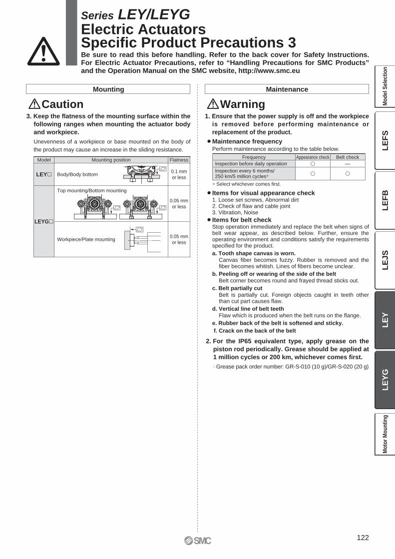
Maintenance
Warning1. Ensure that the power supply is off and the workpiece
is removed before performing maintenance or
replacement of the product.
¡Maintenance frequencyPerform maintenance according to the table below.
¡Items for visual appearance check1. Loose set screws, Abnormal dirt2. Check of fl aw and cable joint3. Vibration, Noise
¡Items for belt checkStop operation immediately and replace the belt when signs of belt wear appear, as described below. Further, ensure the operating environment and conditions satisfy the requirements specifi ed for the product.
a. Tooth shape canvas is worn.Canvas fi ber becomes fuzzy. Rubber is removed and the fi ber becomes whitish. Lines of fi bers become unclear.
b. Peeling off or wearing of the side of the beltBelt corner becomes round and frayed thread sticks out.
c. Belt partially cutBelt is partially cut. Foreign objects caught in teeth other than cut part causes fl aw.
d. Vertical line of belt teethFlaw which is produced when the belt runs on the fl ange.
e. Rubber back of the belt is softened and sticky.
f. Crack on the back of the belt
2. For the IP65 equivalent type, apply grease on the
piston rod periodically. Grease should be applied at
1 million cycles or 200 km, whichever comes fi rst.
· Grease pack order number: GR-S-010 (10 g)/GR-S-020 (20 g)
∗ Select whichever comes fi rst.
3. Keep the fl atness of the mounting surface within the
following ranges when mounting the actuator body
and workpiece.
Unevenness of a workpiece or base mounted on the body of
the product may cause an increase in the sliding resistance.
Mounting
Caution
Series LEY/LEYG Electric ActuatorsSpecifi c Product Precautions 3Be sure to read this before handling. Refer to the back cover for Safety Instructions. For Electric Actuator Precautions, refer to “Handling Precautions for SMC Products” and the Operation Manual on the SMC website, http://www.smc.eu
Model Mounting position Flatness
LEY� Body/Body bottom0.1 mm
or less
LEYG�
Top mounting/Bottom mounting
0.05 mm
or less
Workpiece/Plate mounting0.05 mm
or less
Frequency Appearance check Belt check
Inspection before daily operation � —
Inspection every 6 months/250 km/5 million cycles∗ � �
122
LE
FS
LE
FB
LE
JS
LE
YL
EY
GM
od
el
Se
lec
tio
nM
oto
r M
ou
nti
ng
Lithuania +370 5 2308118 www.smclt.lt [email protected] +31 (0)205318888 www.smc.nl [email protected] +47 67129020 www.smc-norge.no [email protected] +48 222119600 www.smc.pl [email protected] +351 226166570 www.smc.eu [email protected] +40 213205111 www.smcromania.ro [email protected] +7 8127185445 www.smc-pneumatik.ru [email protected] +421 (0)413213212 www.smc.sk [email protected] +386 (0)73885412 www.smc.si [email protected] +34 945184100 www.smc.eu [email protected] +46 (0)86031200 www.smc.nu [email protected] +41 (0)523963131 www.smc.ch [email protected] +90 212 489 0 440 www.smcpnomatik.com.tr [email protected] UK +44 (0)845 121 5122 www.smc.uk [email protected]
Specifications are subject to change without prior notice and any obligation on the part of the manufacturer.
SMC CORPORATION Akihabara UDX 15F, 4-14-1, Sotokanda, Chiyoda-ku, Tokyo 101-0021, JAPAN Phone: 03-5207-8249 FAX: 03-5298-53621st printing XO printing XO 00 Printed in Spain
Austria +43 (0)2262622800 www.smc.at [email protected] +32 (0)33551464 www.smc.be [email protected] +359 (0)2807670 www.smc.bg [email protected] Croatia +385 (0)13707288 www.smc.hr [email protected] Republic +420 541424611 www.smc.cz [email protected] Denmark +45 70252900 www.smcdk.com [email protected] Estonia +372 6510370 www.smcpneumatics.ee [email protected] +358 207513513 www.smc.fi [email protected] +33 (0)164761000 www.smc-france.fr [email protected] +49 (0)61034020 www.smc.de [email protected] +30 210 2717265 www.smchellas.gr [email protected] +36 23513000 www.smc.hu [email protected] +353 (0)14039000 www.smcpneumatics.ie [email protected] +39 0292711 www.smcitalia.it [email protected] +371 67817700 www.smc.lv [email protected]
Safety Instructions Be sure to read “Handling Precautions for SMC Products” (M-E03-3) before using.
SMC Corporation (Europe)
1. The compatibility of the product is the responsibility of the person
who designs the equipment or decides its specifications. Since the product specified here is used under various operating conditions, its
compatibility with specific equipment must be decided by the person who designs the
equipment or decides its specifications based on necessary analysis and test results.
The expected performance and safety assurance of the equipment will be the
responsibility of the person who has determined its compatibility with the product. This
person should also continuously review all specifications of the product referring to its
latest catalogue information, with a view to giving due consideration to any possibility of
equipment failure when configuring the equipment.
2. Only personnel with appropriate training should operate machinery
and equipment. The product specified here may become unsafe if handled incorrectly. The assembly,
operation and maintenance of machines or equipment including our products must be
performed by an operator who is appropriately trained and experienced.
3. . Do not service or attempt to remove product and
machinery/equipment until safety is confirmed.1. The inspection and maintenance of machinery/equipment should only be performed
after measures to prevent falling or runaway of the driven objects have been
confirmed.
2. When the product is to be removed, confirm that the safety measures as mentioned
above are implemented and the power from any appropriate source is cut, and read
and understand the specific product precautions of all relevant products carefully.
3. Before machinery/equipment is restarted, take measures to prevent unexpected
operation and malfunction.
4. Contact SMC beforehand and take special consideration of safety
measures if the product is to be used in any of the following
conditions. 1. Conditions and environments outside of the given specifications, or use outdoors or in
a place exposed to direct sunlight.
2. Installation on equipment in conjunction with atomic energy, railways, air navigation,
space, shipping, vehicles, military, medical treatment, combustion and recreation, or
equipment in contact with food and beverages, emergency stop circuits, clutch and
brake circuits in press applications, safety equipment or other applications unsuitable
for the standard specifications described in the product catalogue.
3. An application which could have negative effects on people, property, or animals
requiring special safety analysis.
4. Use in an interlock circuit, which requires the provision of double interlock for possible
failure by using a mechanical protective function, and periodical checks to confirm
proper operation.
Warning Limited warranty and Disclaimer/Compliance Requirements The product used is subject to the following “Limited warranty and
Disclaimer” and “Compliance Requirements”.
Read and accept them before using the product.
1. The product is provided for use in manufacturing industries.The product herein described is basically provided for peaceful use in manufacturing
industries.
If considering using the product in other industries, consult SMC beforehand and exchange
specifications or a contract if necessary.
If anything is unclear, contact your nearest sales branch.
CautionSMC products are not intended for use as instruments for legal
metrology.Measurement instruments that SMC manufactures or sells have not been qualified by
type approval tests relevant to the metrology (measurement) laws of each country.
Therefore, SMC products cannot be used for business or certification ordained by the
metrology (measurement) laws of each country.
Caution
Limited warranty and Disclaimer
1. The warranty period of the product is 1 year in service or 1.5 years
after the product is delivered, wichever is first.∗2)
Also, the product may have specified durability, running distance or
replacement parts. Please consult your nearest sales branch.
2. For any failure or damage reported within the warranty period which is clearly
our responsibility, a replacement product or necessary parts will be provided.
This limited warranty applies only to our product independently, and not to any
other damage incurred due to the failure of the product.
3. Prior to using SMC products, please read and understand the warranty
terms and disclaimers noted in the specified catalogue for the particular
products.
∗2) Vacuum pads are excluded from this 1 year warranty.
A vacuum pad is a consumable part, so it is warranted for a year after it is delivered.
Also, even within the warranty period, the wear of a product due to the use of the vacuum
pad or failure due to the deterioration of rubber material are not covered by the limited
warranty.
Compliance Requirements
1. The use of SMC products with production equipment for the manufacture of
weapons of mass destruction (WMD) or any other weapon is strictly
prohibited.
2. The exports of SMC products or technology from one country to another are
governed by the relevant security laws and regulations of the countries
involved in the transaction. Prior to the shipment of a SMC product to
another country, assure that all local rules governing that export are known
and followed.
These safety instructions are intended to prevent hazardous situations and/or equipment damage. These instructions indicate the level of potential hazard with the labels of “Caution,” “Warning” or “Danger.” They are all important notes for safety and must be followed in addition to International Standards (ISO/IEC)∗1), and other safety regulations.
∗1) ISO 4414: Pneumatic fluid power – General rules relating to systems.
ISO 4413: Hydraulic fluid power – General rules relating to systems.
IEC 60204-1: Safety of machinery – Electrical equipment of machines.
(Part 1: General requirements)
ISO 10218-1: Manipulating industrial robots - Safety.
etc.
Caution indicates a hazard with a low level of risk which, if not avoided, could result in minor or moderate injury.
Warning indicates a hazard with a medium level of risk which, if not avoided, could result in death or serious injury.
Caution:
Warning:
Danger :Danger indicates a hazard with a high level of risk which, if not avoided, will result in death or serious injury.
Safety Instructions