Motion Solutions - Elec.ru
92
Motion Solutions Flexible Solutions for Improved Machine Productivity GE Intelligent Platforms
Transcript of Motion Solutions - Elec.ru

Motion SolutionsFlexible Solutions for Improved Machine Productivity
GEIntelligent Platforms

TABLE OF CONTENTS
Motion Controllers . . . . . . . . . . . . . . . . . . . . . . . . . . 3
PACMotion . . . . . . . . . . . . . . . . . . . . . . . . . . . . . . . . . . 3
Servo Amplifiers . . . . . . . . . . . . . . . . . . . . . . . . . . . 17
VersaMotion Series . . . . . . . . . . . . . . . . . . . . . . . . . 18
αi and βi Series . . . . . . . . . . . . . . . . . . . . . . . . . . . . 36
Servo Motors . . . . . . . . . . . . . . . . . . . . . . . . . . . . . . 51
VersaMotion Motors . . . . . . . . . . . . . . . . . . . . . . . . 28
αi Series . . . . . . . . . . . . . . . . . . . . . . . . . . . . . . . . . . . 53
βi Series . . . . . . . . . . . . . . . . . . . . . . . . . . . . . . . . . . . 73
Motion Software . . . . . . . . . . . . . . . . . . . . . . . . . . . 83
Servo Sizing Software . . . . . . . . . . . . . . . . . . . . . . 83
Product Number Index . . . . . . . . . . . . . . . . . . . . . . 84
Motion Solutions
2 Motion Solutions Catalog
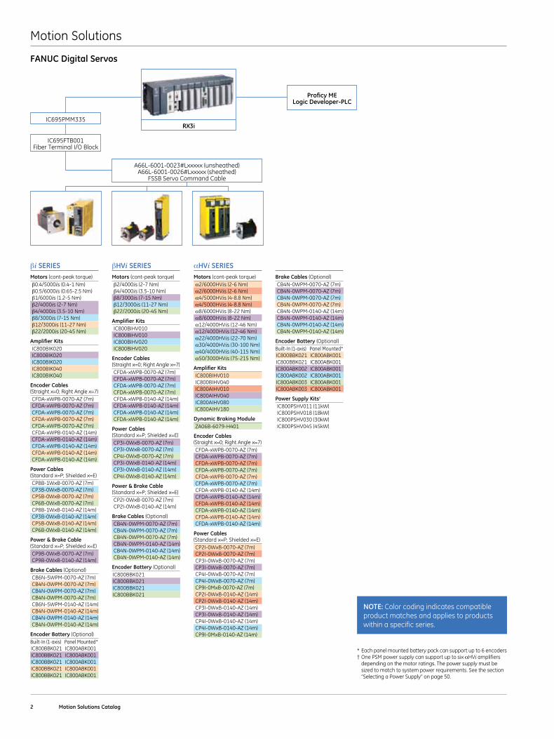
βi SERIESMotors (cont-peak torque)β0 .4/5000is (0 .4-1 Nm)β0 .5/6000is (0 .65-2 .5 Nm)β1/6000is (1 .2-5 Nm)β2/4000is (2-7 Nm)β4/4000is (3 .5-10 Nm)β8/3000is (7-15 Nm)β12/3000is (11-27 Nm)β22/2000is (20-45 Nm)
Amplifier KitsIC800BIK020IC800BIK020IC800BIK020IC800BIK040IC800BIK040
Encoder Cables (Straight x=0; Right Angle x=7)CFDA-xWPB-0070-AZ (7m)CFDA-xWPB-0070-AZ (7m) CFDA-xWPB-0070-AZ (7m)CFDA-xWPB-0070-AZ (7m)CFDA-xWPB-0070-AZ (7m)CFDA-xWPB-0140-AZ (14m)CFDA-xWPB-0140-AZ (14m)CFDA-xWPB-0140-AZ (14m)CFDA-xWPB-0140-AZ (14m)CFDA-xWPB-0140-AZ (14m)
Power Cables (Standard x=P; Shielded x=E)CP8B-1WxB-0070-AZ (7m)CP3B-0WxB-0070-AZ (7m)CP5B-0WxB-0070-AZ (7m)CP6B-0WxB-0070-AZ (7m)CP8B-1WxB-0140-AZ (14m)CP3B-0WxB-0140-AZ (14m)CP5B-0WxB-0140-AZ (14m)CP6B-0WxB-0140-AZ (14m)
Power & Brake Cable (Standard x=P; Shielded x=E)CP9B-0WxB-0070-AZ (7m)CP9B-0WxB-0140-AZ (14m)
Brake Cables (Optional)CB6N-5WPM-0070-AZ (7m)CB4N-0WPM-0070-AZ (7m)CB4N-0WPM-0070-AZ (7m)CB4N-0WPM-0070-AZ (7m)CB6N-5WPM-0140-AZ (14m)CB4N-0WPM-0140-AZ (14m)CB4N-0WPM-0140-AZ (14m)CB4N-0WPM-0140-AZ (14m)
Encoder Battery (Optional)Built-In (1-axis) Panel Mounted*IC800BBK021 IC800ABK001IC800BBK021 IC800ABK001IC800BBK021 IC800ABK001IC800BBK021 IC800ABK001IC800BBK021 IC800ABK001
αHVi SERIESMotors (cont-peak torque)α2/6000HVis (2-6 Nm)α2/6000HVis (2-6 Nm)α4/5000HVis (4-8 .8 Nm)α4/5000HVis (4-8 .8 Nm)α8/6000HVis (8-22 Nm)α8/6000HVis (8-22 Nm)α12/4000HVis (12-46 Nm)α12/4000HVis (12-46 Nm)α22/4000HVis (22-70 Nm)α30/4000HVis (30-100 Nm)α40/4000HVis (40-115 Nm)α50/3000HVis (75-215 Nm)
Amplifier KitsIC800BIHV010IC800BIHV040IC800AIHV010IC800AIHV040IC800AIHV080IC800AIHV180
Dynamic Braking ModuleZA06B-6079-H401
Encoder Cables (Straight x=0; Right Angle x=7)CFDA-xWPB-0070-AZ (7m)CFDA-xWPB-0070-AZ (7m)CFDA-xWPB-0070-AZ (7m) CFDA-xWPB-0070-AZ (7m)CFDA-xWPB-0070-AZ (7m)CFDA-xWPB-0070-AZ (7m)CFDA-xWPB-0140-AZ (14m)CFDA-xWPB-0140-AZ (14m)CFDA-xWPB-0140-AZ (14m)CFDA-xWPB-0140-AZ (14m)CFDA-xWPB-0140-AZ (14m)CFDA-xWPB-0140-AZ (14m)
Power Cables (Standard x=P; Shielded x=E)CP2I-0WxB-0070-AZ (7m)CP2I-0WxB-0070-AZ (7m)CP3I-0WxB-0070-AZ (7m)CP3I-0WxB-0070-AZ (7m)CP4I-0WxB-0070-AZ (7m)CP4I-0WxB-0070-AZ (7m)CP9I-0MxB-0070-AZ (7m)CP2I-0WxB-0140-AZ (14m)CP2I-0WxB-0140-AZ (14m)CP3I-0WxB-0140-AZ (14m)CP3I-0WxB-0140-AZ (14m)CP4I-0WxB-0140-AZ (14m)CP4I-0WxB-0140-AZ (14m)CP9I-0MxB-0140-AZ (14m)
Brake Cables (Optional)CB4N-0WPM-0070-AZ (7m)CB4N-0WPM-0070-AZ (7m)CB4N-0WPM-0070-AZ (7m)CB4N-0WPM-0070-AZ (7m)CB4N-0WPM-0140-AZ (14m)CB4N-0WPM-0140-AZ (14m)CB4N-0WPM-0140-AZ (14m)CB4N-0WPM-0140-AZ (14m)
Encoder Battery (Optional)Built-In (1-axis) Panel Mounted*IC800BBK021 IC800ABK001IC800BBK021 IC800ABK001IC800ABK002 IC800ABK001IC800ABK002 IC800ABK001IC800ABK003 IC800ABK001IC800ABK003 IC800ABK001
Power Supply Kits†
IC800PSHV011 (11kW)IC800PSHV018 (18kW)IC800PSHV030 (30kW)IC800PSHV045 (45kW)
βHVi SERIESMotors (cont-peak torque)β2/4000is (2-7 Nm)β4/4000is (3 .5-10 Nm)β8/3000is (7-15 Nm)β12/3000is (11-27 Nm)β22/2000is (20-45 Nm)
Amplifier KitsIC800BIHV010IC800BIHV010IC800BIHV020IC800BIHV020
Encoder Cables (Straight x=0; Right Angle x=7)CFDA-xWPB-0070-AZ (7m) CFDA-xWPB-0070-AZ (7m)CFDA-xWPB-0070-AZ (7m)CFDA-xWPB-0070-AZ (7m)CFDA-xWPB-0140-AZ (14m)CFDA-xWPB-0140-AZ (14m)CFDA-xWPB-0140-AZ (14m)CFDA-xWPB-0140-AZ (14m)
Power Cables (Standard x=P; Shielded x=E)CP3I-0WxB-0070-AZ (7m)CP3I-0WxB-0070-AZ (7m)CP4I-0WxB-0070-AZ (7m)CP3I-0WxB-0140-AZ (14m)CP3I-0WxB-0140-AZ (14m)CP4I-0WxB-0140-AZ (14m)
Power & Brake Cable (Standard x=P; Shielded x=E)CP2I-0WxB-0070-AZ (7m)CP2I-0WxB-0140-AZ (14m)
Brake Cables (Optional)CB4N-0WPM-0070-AZ (7m)CB4N-0WPM-0070-AZ (7m)CB4N-0WPM-0070-AZ (7m)CB4N-0WPM-0140-AZ (14m)CB4N-0WPM-0140-AZ (14m)CB4N-0WPM-0140-AZ (14m)
Encoder Battery (Optional)IC800BBK021IC800BBK021IC800BBK021IC800BBK021
Proficy ME Logic Developer-PLC
A66L-6001-0023#Lxxxxx (unsheathed)A66L-6001-0026#Lxxxxx (sheathed)
FSSB Servo Command Cable
RX3i
NOTE: Color coding indicates compatible product matches and applies to products within a specific series .
* Each panel mounted battery pack can support up to 6 encoders† One PSM power supply can support up to six αHVi amplifiers
depending on the motor ratings . The power supply must be sized to match to system power requirements . See the section “Selecting a Power Supply” on page 50 .
FANUC Digital Servos
IC695FTB001Fiber Terminal I/O Block
IC695PMM335
Motion Solutions
GE Intelligent Platforms | www .ge-ip .com 3
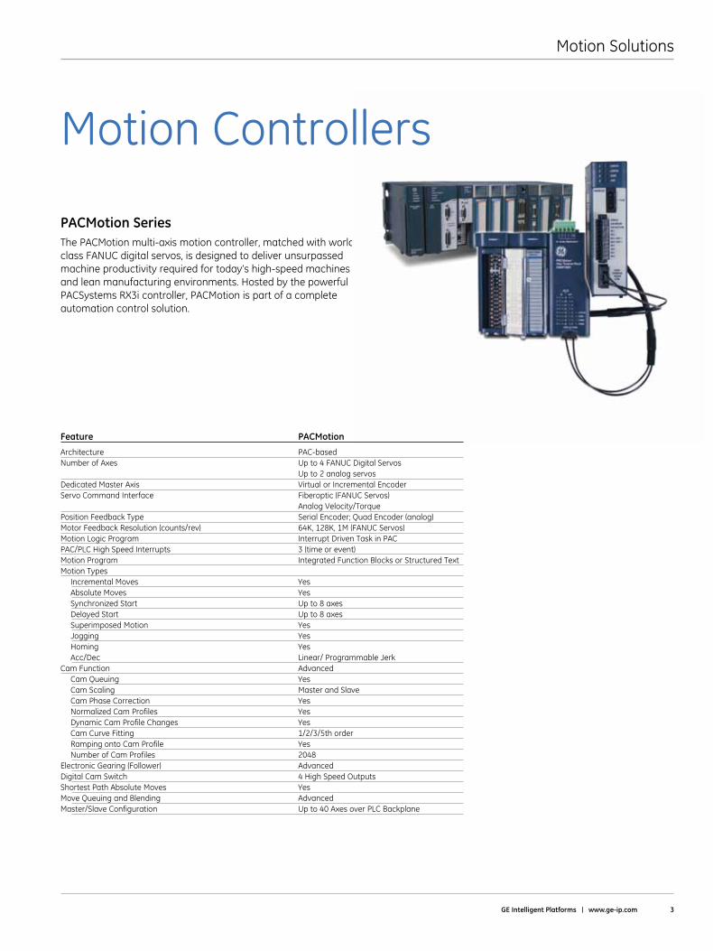
PACMotion SeriesThe PACMotion multi-axis motion controller, matched with world class FANUC digital servos, is designed to deliver unsurpassed machine productivity required for today’s high-speed machines and lean manufacturing environments . Hosted by the powerful PACSystems RX3i controller, PACMotion is part of a complete automation control solution .
Feature PACMotion
Architecture PAC-basedNumber of Axes Up to 4 FANUC Digital Servos Up to 2 analog servosDedicated Master Axis Virtual or Incremental EncoderServo Command Interface Fiberoptic (FANUC Servos) Analog Velocity/TorquePosition Feedback Type Serial Encoder; Quad Encoder (analog)Motor Feedback Resolution (counts/rev) 64K, 128K, 1M (FANUC Servos)Motion Logic Program Interrupt Driven Task in PACPAC/PLC High Speed Interrupts 3 (time or event)Motion Program Integrated Function Blocks or Structured TextMotion Types Incremental Moves Yes Absolute Moves Yes Synchronized Start Up to 8 axes Delayed Start Up to 8 axes Superimposed Motion Yes Jogging Yes Homing Yes Acc/Dec Linear/ Programmable JerkCam Function Advanced Cam Queuing Yes Cam Scaling Master and Slave Cam Phase Correction Yes Normalized Cam Profiles Yes Dynamic Cam Profile Changes Yes Cam Curve Fitting 1/2/3/5th order Ramping onto Cam Profile Yes Number of Cam Profiles 2048Electronic Gearing (Follower) AdvancedDigital Cam Switch 4 High Speed OutputsShortest Path Absolute Moves YesMove Queuing and Blending AdvancedMaster/Slave Configuration Up to 40 Axes over PLC Backplane
Motion Controllers
Motion Solutions
4 Motion Solutions Catalog
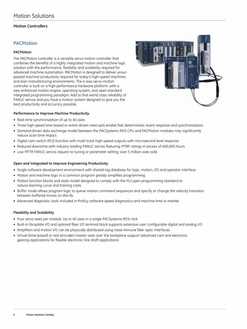
PACMotion
The PACMotion controller is a versatile servo motion controller that combines the benefits of a highly integrated motion and machine logic solution with the performance, flexibility and scalability required for advanced machine automation . PACMotion is designed to deliver unsur-passed machine productivity required for today’s high-speed machines and lean manufacturing environments . The 4-axis servo motion controller is built on a high performance hardware platform, with a new enhanced motion engine, operating system, and open standard integrated programming paradigm . Add to that world class reliability of FANUC servos and you have a motion system designed to give you the best productivity and accuracy possible .
Performance to Improve Machine Productivity
• Real-timesynchronizationofupto40axes
• Threehighspeedtime-basedorevent-driveninterruptsenablefastdeterministiceventresponseandsynchronization
• Demand-drivendataexchangemodelbetweenthePACSystemsRX3iCPUandPACMotionmodulesmaysignificantly reduce scan time impact
• Digitalcamswitch(PLS)functionwithmulti-trackhigh-speedoutputswithmicrosecondlevelresponse
• ReduceddowntimewithindustryleadingFANUCservosfeaturingMTBFratingsinexcessof400,000hours
• LowMTTRFANUCservosrequirenotuningorparametersetting;over5millionaxessold
Open and Integrated to Improve Engineering Productivity
• Singlesoftwaredevelopmentenvironmentwithsharedtagdatabaseforlogic,motion,I/Oandoperatorinterface
• Motionandmachinelogicinacommonprogramgreatlysimplifiesprogramming
• MotionfunctionblocksandstatemodeldesignedtocomplywiththePLCopenprogrammingstandardto reduce learning curve and training costs
• Buffermodeallowsprogramlogictoqueuemotioncommandsequencesandspecifyorchangethevelocitytransition between buffered moves on-the-fly
• AdvanceddiagnostictoolsincludedinProficysoftwarespeeddiagnosticsandmachinetimetomarket
Flexibility and Scalability
• Fourservoaxespermodule;Upto40axesinasinglePACSystemsRX3irack
• Built-infaceplateI/OandoptionalfiberI/OterminalblocksupportsextensiveuserconfigurabledigitalandanalogI/O
• AmplifiersandmotionI/Ocanbephysicallydistributedusingnoiseimmunefiberopticinterfaces
• Virtual(time-based)orreal(encoder)masteraxesoverthebackplanesupportadvancedcamandelectronic gearing applications for flexible electronic line shaft applications
Motion Controllers
PACMotion
Motion Solutions
GE Intelligent Platforms | www .ge-ip .com 5
Enter ExitPrev Next Select Remove
Control Keyboard Options
Help
STATUS MONITORING: GE FANUC--CIMPLICITY
Exit
Machine 2 Production Status
High Speed Pressure Readings
Temperature Readings
Prdt Rate
Good Rate 100 %
38 %Month 11 Day
Cycle T4.36 Sec
Sec
Sec
InIn
Inj . T0.72
Ext. T2.42
Shot Size
1.467
Order Completion Date 7
Plan 167885
Shot 941
Pro Count 5
Good Prdt. 4705
Good Shot 941
Product Number PRDT-0004
Product Name Cover
M-CUSH
0.204
Nozzle or Barrel
Hold
32
400
200
032
1 2 1 2 3 4 5 6 7 8
419 387 369 303 0 0 0 0
Order Info
Help
Machine 2
ALARM
Proficy Machine EditionLogic Developer – PLC
Operator Interface
PACSystemsRX3i
Fiber Terminal Block(FTB)
Terminal Board
VersaMotionSeries
Amplifierand Motor
VersaMotionSeries
Amplifierand Motor
Terminal Board
βis/βHVis SeriesServo Motor
βis/βHVis SeriesServo Motor
βis/βHVis SeriesServo Motor
βis/βHVis SeriesServo Motor
βi/βHVi SeriesAmplifier
βi/βHVi SeriesAmplifier
βi/βHVi SeriesAmplifier
βi/βHVi SeriesAmplifier
PSM-HViPower Supply
αHVi SeriesAmplifier
αHVi SeriesAmplifier
αHVi SeriesAmplifier
αHVi SeriesAmplifier
αHVi/αHVis SeriesServo Motor
αHVi/αHVis SeriesServo Motor
αHVi/αHVis SeriesServo Motor
αHVi/αHVis SeriesServo Motor
C
D
FF
E
A
D
D D D D
D D D
B
FANUCFANUC
FANUCFANUC
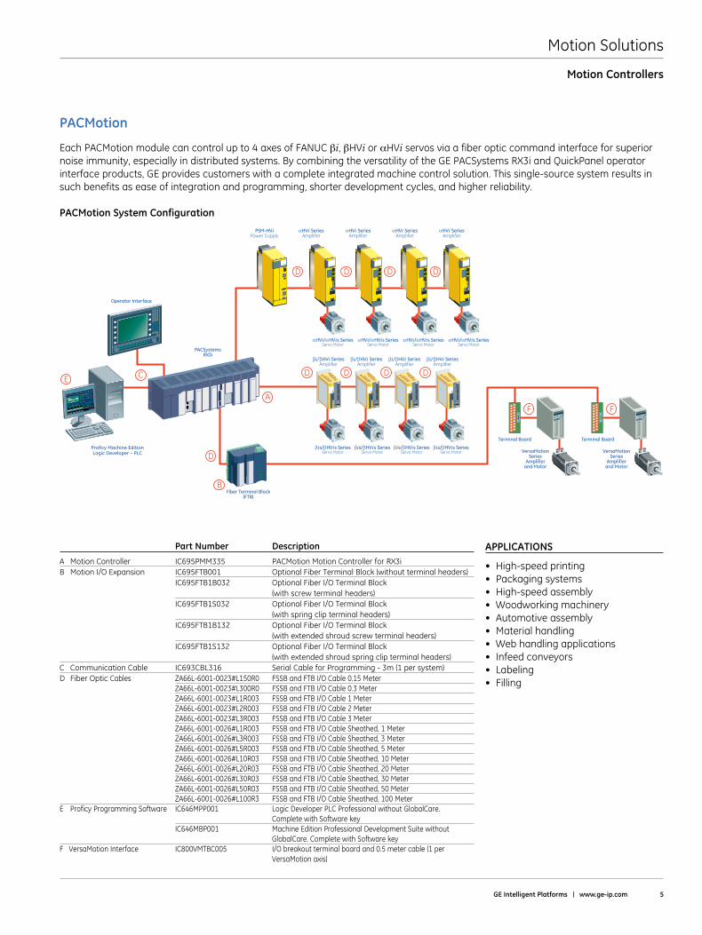
Each PACMotion module can control up to 4 axes of FANUC βi, βHVi or αHVi servos via a fiber optic command interface for superior noise immunity, especially in distributed systems . By combining the versatility of the GE PACSystems RX3i and QuickPanel operator interface products, GE provides customers with a complete integrated machine control solution . This single-source system results in such benefits as ease of integration and programming, shorter development cycles, and higher reliability .
PACMotion System Configuration
APPLICATIONS
• High-speedprinting• Packagingsystems• High-speedassembly• Woodworkingmachinery• Automotiveassembly• Materialhandling• Webhandlingapplications• Infeedconveyors• Labeling• Filling
Motion Controllers
PACMotion
Part Number Description
A Motion Controller IC695PMM335 PACMotion Motion Controller for RX3iB Motion I/O Expansion IC695FTB001 Optional Fiber Terminal Block (without terminal headers) IC695FTB1B032 Optional Fiber I/O Terminal Block (with screw terminal headers) IC695FTB1S032 Optional Fiber I/O Terminal Block (with spring clip terminal headers) IC695FTB1B132 Optional Fiber I/O Terminal Block (with extended shroud screw terminal headers) IC695FTB1S132 Optional Fiber I/O Terminal Block (with extended shroud spring clip terminal headers)C Communication Cable IC693CBL316 Serial Cable for Programming - 3m (1 per system)D Fiber Optic Cables ZA66L-6001-0023#L150R0 FSSB and FTB I/O Cable 0 .15 Meter ZA66L-6001-0023#L300R0 FSSB and FTB I/O Cable 0 .3 Meter ZA66L-6001-0023#L1R003 FSSB and FTB I/O Cable 1 Meter ZA66L-6001-0023#L2R003 FSSB and FTB I/O Cable 2 Meter ZA66L-6001-0023#L3R003 FSSB and FTB I/O Cable 3 Meter ZA66L-6001-0026#L1R003 FSSB and FTB I/O Cable Sheathed, 1 Meter ZA66L-6001-0026#L3R003 FSSB and FTB I/O Cable Sheathed, 3 Meter ZA66L-6001-0026#L5R003 FSSB and FTB I/O Cable Sheathed, 5 Meter ZA66L-6001-0026#L10R03 FSSB and FTB I/O Cable Sheathed, 10 Meter ZA66L-6001-0026#L20R03 FSSB and FTB I/O Cable Sheathed, 20 Meter ZA66L-6001-0026#L30R03 FSSB and FTB I/O Cable Sheathed, 30 Meter ZA66L-6001-0026#L50R03 FSSB and FTB I/O Cable Sheathed, 50 Meter ZA66L-6001-0026#L100R3 FSSB and FTB I/O Cable Sheathed, 100 MeterE Proficy Programming Software IC646MPP001 Logic Developer PLC Professional without GlobalCare . Complete with Software key IC646MBP001 Machine Edition Professional Development Suite without GlobalCare . Complete with Software keyF VersaMotion Interface IC800VMTBC005 I/O breakout terminal board and 0 .5 meter cable (1 per VersaMotion axis)
Motion Solutions
6 Motion Solutions Catalog
PACMotion Controller Features
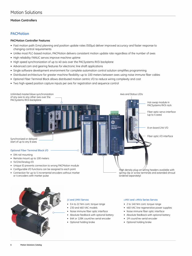
• Fastmotionpath(1ms)planningandpositionupdaterates(500µs)deliverimprovedaccuracyandfasterresponseto changing control requirements
• UnlikemostPLC-basedmotion,PACMotiondeliversconsistentmotionupdaterateregardlessofthenumberofaxes
• HighreliabilityFANUCservosimprovemachineuptime
• Highspeedsynchronizationofupto40axisoverthePACSystemsRX3ibackplane
• Advancedcamandgearingfeaturesforelectroniclineshaftapplications
• Singlesoftwaredevelopmentenvironmentforcompleteautomationcontrolsolutionsimplifiesprogramming
• Distributedarchitectureforgreatermachineflexibility–upto100metersbetweenaxesusingnoiseimmunefibercables
• OptionalFiberTerminalBlockallowsdistributedmotioncentricI/Otoreducewiringcomplexityandcost
• Twohigh-speedpositioncaptureinputsperaxisforregistrationandsequencecontrol
Optional Fiber Terminal Block I/O
• DINrailmounting• Remotemountupto100meters• 5V/24V/AnalogI/O• UniqueIDpreventsconnectiontowrongPACMotionmodule• ConfigurableI/Ofunctionscanbeassignedtoeachpoint• Connectionforupto5incrementalencoderswithoutmarker
or 4 encoders with marker pulse
High density plug-on wiring headers available with spring clip or screw terminals and extended shroud (ordered separately)
Unlimited master/slave synchronization of any axis to any other axis over the PACSystems RX3i backplane
Axis and Status LEDs
Hot-swap module in PACSystems RX3i rack
Fiber optic servo interface (up to 4 axes)
8 on-board 24V I/O
Fiber optic I/O interfaceSynchronized or delayed start of up to any 8 axes
Motion Controllers
PACMotion
βi and βHVi Servos
• 0.4to22Nmcont.torquerange• 230and460VACmodels• Noiseimmunefiberopticinterface• Absolutefeedbackwithoptionalbattery• 64Kor128Kcount/revserialencoder• Optionalholdingbrake
αHVi and αHVis Series Servos
• 2to140Nmcont.torquerange• 460VAClineregenerativepowersupplies• Noiseimmunefiberopticinterface• Absolutefeedbackwithoptionalbattery• 1Mcount/revserialencoder• Optionalholdingbrake
Motion Solutions
GE Intelligent Platforms | www .ge-ip .com 7
Motion Controllers
PACMotion
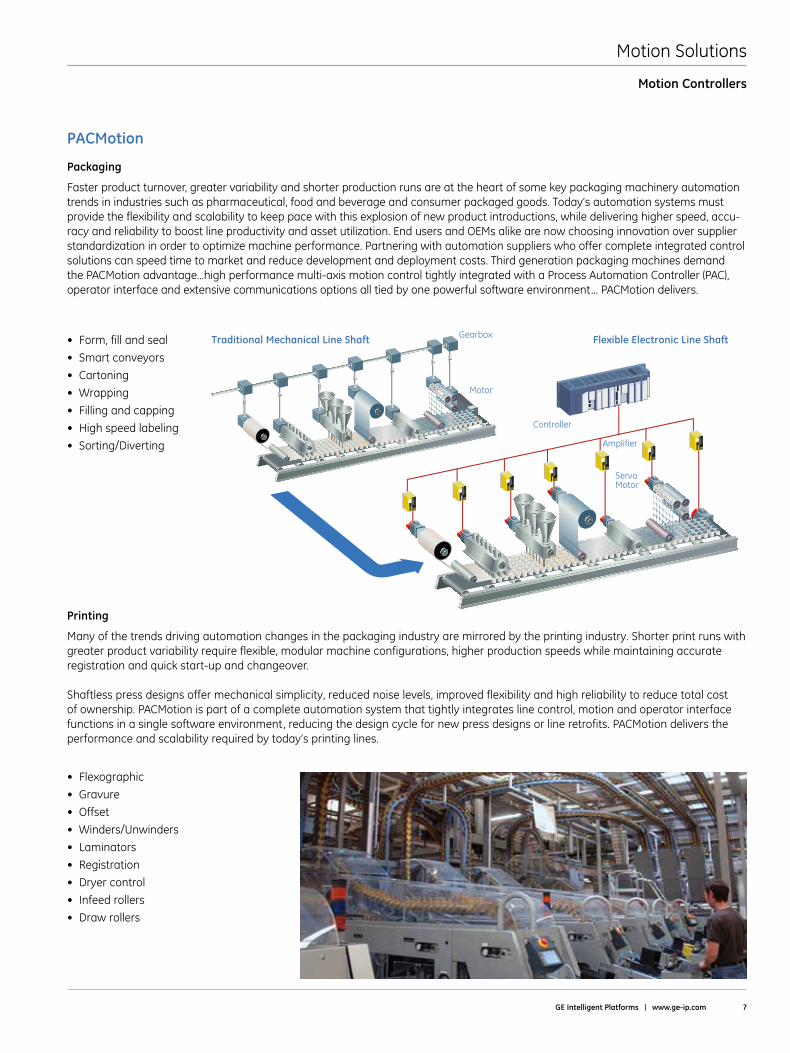
Traditional Mechanical Line Shaft Gearbox
Motor
Amplifier
Servo Motor
Controller
Flexible Electronic Line Shaft
Packaging
Faster product turnover, greater variability and shorter production runs are at the heart of some key packaging machinery automation trends in industries such as pharmaceutical, food and beverage and consumer packaged goods . Today’s automation systems must provide the flexibility and scalability to keep pace with this explosion of new product introductions, while delivering higher speed, accu-racy and reliability to boost line productivity and asset utilization . End users and OEMs alike are now choosing innovation over supplier standardization in order to optimize machine performance . Partnering with automation suppliers who offer complete integrated control solutions can speed time to market and reduce development and deployment costs . Third generation packaging machines demand the PACMotion advantage…high performance multi-axis motion control tightly integrated with a Process Automation Controller (PAC), operator interface and extensive communications options all tied by one powerful software environment . . . PACMotion delivers .
Printing
Many of the trends driving automation changes in the packaging industry are mirrored by the printing industry . Shorter print runs with greater product variability require flexible, modular machine configurations, higher production speeds while maintaining accurate registration and quick start-up and changeover .
Shaftless press designs offer mechanical simplicity, reduced noise levels, improved flexibility and high reliability to reduce total cost of ownership . PACMotion is part of a complete automation system that tightly integrates line control, motion and operator interface functions in a single software environment, reducing the design cycle for new press designs or line retrofits . PACMotion delivers the performance and scalability required by today’s printing lines .
• Form,fillandseal
• Smartconveyors
• Cartoning
• Wrapping
• Fillingandcapping
• Highspeedlabeling
• Sorting/Diverting
• Flexographic
• Gravure
• Offset
• Winders/Unwinders
• Laminators
• Registration
• Dryercontrol
• Infeedrollers
• Drawrollers

Motion Solutions
8 Motion Solutions Catalog
Material Handling and High-Speed Assembly
Price pressure, smaller products and shorter life cycles in automotive, medical and electronic products require lean manufacturing lines with the flexibility to allow assemblers to reduce time to market for new products and build many product variations on the same line .
Smaller products require automation and motion control systems that can meet the increased assembly precision at ever increasing produc-tion speeds . System reliability is a crucial element to maintaining the high production rates necessary to reduce total cost per assembly .
PACMotion is part of a complete automation system that tightly integrates material handling and assembly line control, motion and operator interface functions in a single software environment, improving engineering productivity and delivering faster time to market . PACMotion delivers the precision and flexibility to meet demanding assembly and handling challenges .
Converting and Web Handling
Increasing line speed while reducing scrap is a critical factor in maintaining a competitive edge in the web handling and material converting applications . Greater product variability requires flexible modular control systems that enable instant changeover from one product run to the next . Adjusting for different web widths, repositioning edge guides and slitter position, changing cut length, and rewind tension must be fast and accurate . Servo control technology replaces traditional mechanical adjustments, allowing for precise and repeatable adjustments . Programmable jerk control reduces web breaks and film stretching while high servo response ensures fast corrections to web disturbances . PACMotion is part of an integrated automation system for device and I/O control, motion and operator interface to facilitate efficient programming and powerful diagnostics in a single software environment .
• Engine/TransmissionAssembly
• TransferLines
• TestStands
• RotaryDialTables
• ElectronicAssembly
• AdhesiveDispensing
• SmartConveyors
• BaggageHandlingSystems
• Laminating
• CartonFolding
• RotaryDieCutting
• Folder/Gluers
• Unwinders/Rewinders
• SlitterPositioning
Motion Controllers
PACMotion
Motion Solutions
GE Intelligent Platforms | www .ge-ip .com 9
Open and Integrated to Improve Engineering Productivity
Synchronization of separate motion and logic programs and the lack of open motion programming standards can present a challenge even for simple motion applications . Proficy Machine Edition provides one tool for control, view, and motion and provides one universal engineering development environment for all programming, configuration, and diagnostics, resulting in faster time to solution, reduced training, and more compact, efficient design . The high level of PACMotion integration with the RX3i platform can significantly reduce system engineering and commissioning costs:
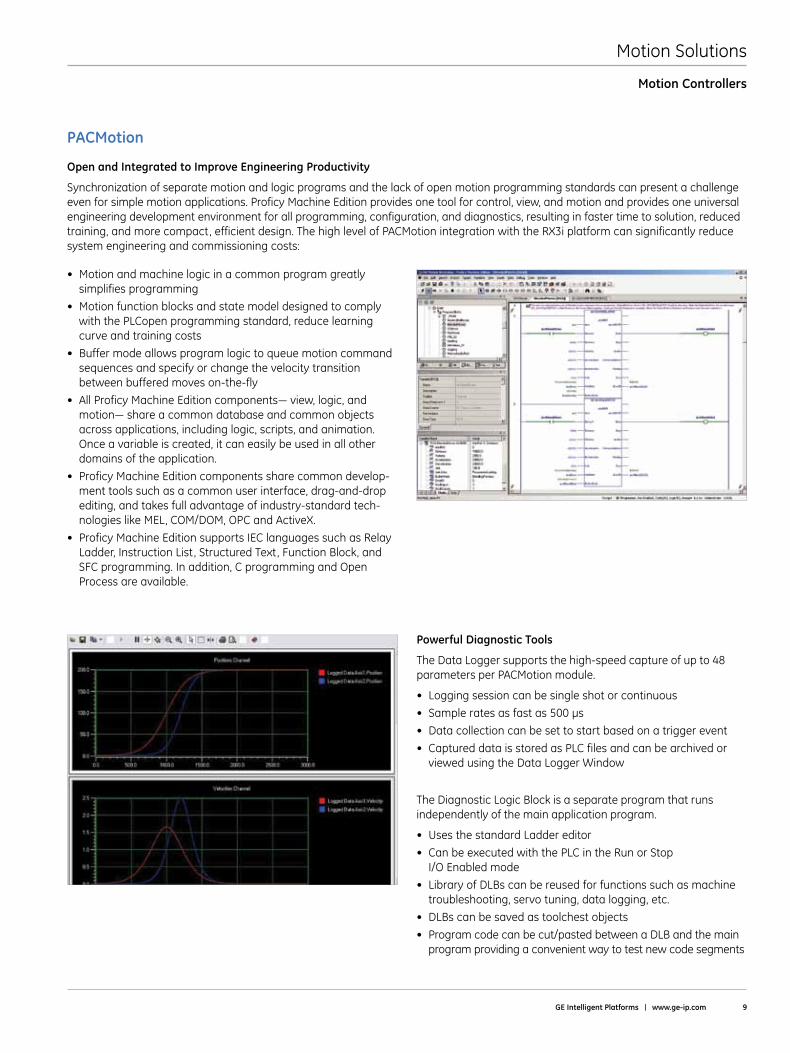
Powerful Diagnostic Tools
The Data Logger supports the high-speed capture of up to 48 parameters per PACMotion module .
• Loggingsessioncanbesingleshotorcontinuous
• Sampleratesasfastas500µs
• Datacollectioncanbesettostartbasedonatriggerevent
• CaptureddataisstoredasPLCfilesandcanbearchivedorviewed using the Data Logger Window
The Diagnostic Logic Block is a separate program that runs independently of the main application program .
• UsesthestandardLaddereditor
• CanbeexecutedwiththePLCintheRunorStop I/O Enabled mode
• LibraryofDLBscanbereusedforfunctionssuchasmachinetroubleshooting, servo tuning, data logging, etc .
• DLBscanbesavedastoolchestobjects
• Programcodecanbecut/pastedbetweenaDLBandthemainprogram providing a convenient way to test new code segments
Motion Controllers
PACMotion
• Motionandmachinelogicinacommonprogramgreatlysimplifies programming
• Motionfunctionblocksandstatemodeldesignedtocomplywith the PLCopen programming standard, reduce learning curve and training costs
•Buffermodeallowsprogramlogictoqueuemotioncommandsequences and specify or change the velocity transition between buffered moves on-the-fly
•AllProficyMachineEditioncomponents—view,logic,andmotion—shareacommondatabaseandcommonobjectsacross applications, including logic, scripts, and animation . Once a variable is created, it can easily be used in all other domains of the application .
•ProficyMachineEditioncomponentssharecommondevelop-ment tools such as a common user interface, drag-and-drop editing, and takes full advantage of industry-standard tech-nologies like MEL, COM/DOM, OPC and ActiveX .
•ProficyMachineEditionsupportsIEClanguagessuchasRelayLadder, Instruction List, Structured Text, Function Block, and SFC programming . In addition, C programming and Open Process are available .
Motion Solutions
10 Motion Solutions Catalog
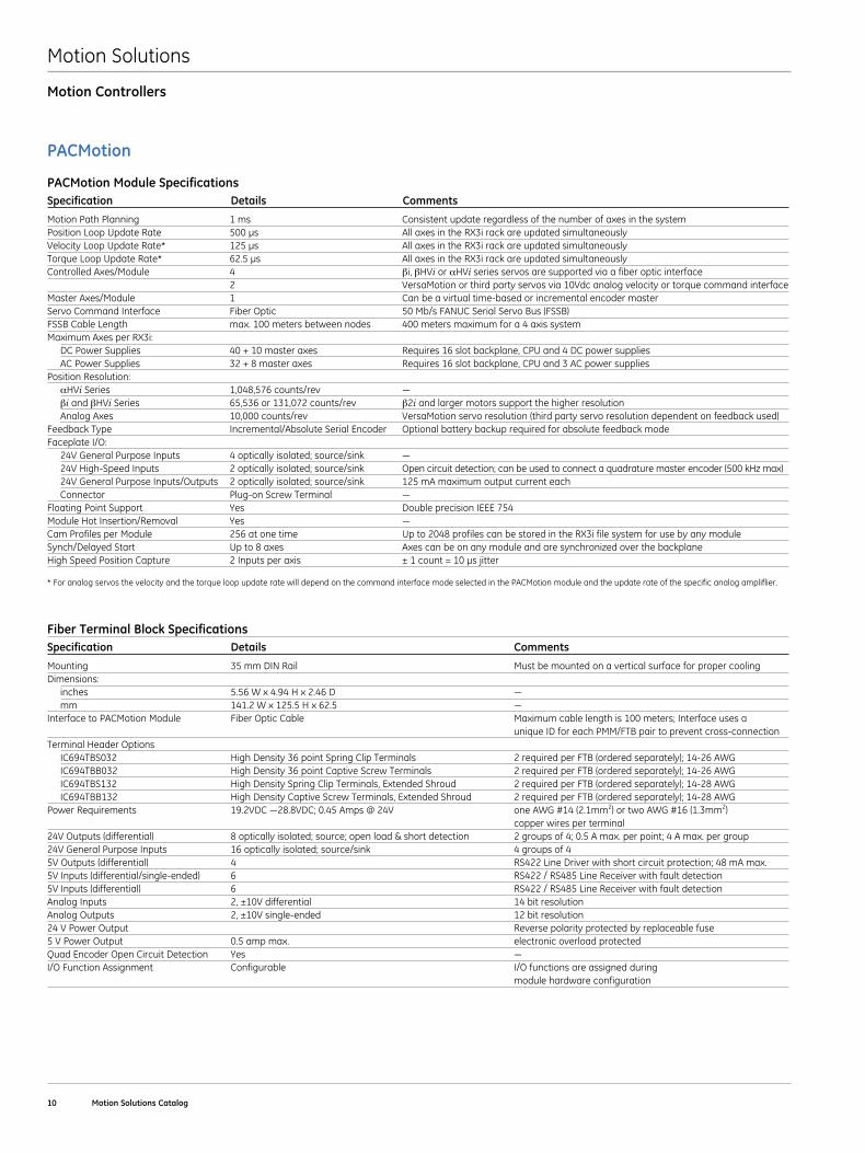
PACMotion Module SpecificationsSpecification Details Comments
Motion Path Planning 1 ms Consistent update regardless of the number of axes in the systemPositionLoopUpdateRate 500µs AllaxesintheRX3irackareupdatedsimultaneouslyVelocityLoopUpdateRate* 125µs AllaxesintheRX3irackareupdatedsimultaneouslyTorqueLoopUpdateRate* 62.5µs AllaxesintheRX3irackareupdatedsimultaneouslyControlled Axes/Module 4 βi, βHVi or αHVi series servos are supported via a fiber optic interface 2 VersaMotion or third party servos via 10Vdc analog velocity or torque command interfaceMaster Axes/Module 1 Can be a virtual time-based or incremental encoder masterServo Command Interface Fiber Optic 50 Mb/s FANUC Serial Servo Bus (FSSB) FSSB Cable Length max . 100 meters between nodes 400 meters maximum for a 4 axis systemMaximum Axes per RX3i: DC Power Supplies 40 + 10 master axes Requires 16 slot backplane, CPU and 4 DC power supplies AC Power Supplies 32 + 8 master axes Requires 16 slot backplane, CPU and 3 AC power suppliesPosition Resolution: αHViSeries 1,048,576counts/rev — βi and βHVi Series 65,536 or 131,072 counts/rev β2i and larger motors support the higher resolution Analog Axes 10,000 counts/rev VersaMotion servo resolution (third party servo resolution dependent on feedback used)Feedback Type Incremental/Absolute Serial Encoder Optional battery backup required for absolute feedback modeFaceplate I/O: 24VGeneralPurposeInputs 4opticallyisolated;source/sink — 24V High-Speed Inputs 2 optically isolated; source/sink Open circuit detection; can be used to connect a quadrature master encoder (500 kHz max) 24V General Purpose Inputs/Outputs 2 optically isolated; source/sink 125 mA maximum output current each Connector Plug-onScrewTerminal — Floating Point Support Yes Double precision IEEE 754ModuleHotInsertion/Removal Yes —Cam Profiles per Module 256 at one time Up to 2048 profiles can be stored in the RX3i file system for use by any moduleSynch/Delayed Start Up to 8 axes Axes can be on any module and are synchronized over the backplaneHighSpeedPositionCapture 2Inputsperaxis ±1count=10µsjitter
* For analog servos the velocity and the torque loop update rate will depend on the command interface mode selected in the PACMotion module and the update rate of the specific analog ampliflier .
Fiber Terminal Block Specifications Specification Details Comments
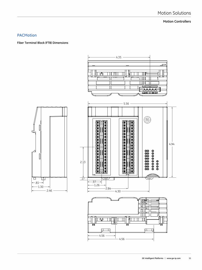
Mounting 35 mm DIN Rail Must be mounted on a vertical surface for proper coolingDimensions: inches 5.56Wx4.94Hx2.46D — mm 141.2Wx125.5Hx62.5 —Interface to PACMotion Module Fiber Optic Cable Maximum cable length is 100 meters; Interface uses a unique ID for each PMM/FTB pair to prevent cross-connectionTerminal Header Options IC694TBS032 High Density 36 point Spring Clip Terminals 2 required per FTB (ordered separately); 14-26 AWG IC694TBB032 High Density 36 point Captive Screw Terminals 2 required per FTB (ordered separately); 14-26 AWG IC694TBS132 High Density Spring Clip Terminals, Extended Shroud 2 required per FTB (ordered separately); 14-28 AWG IC694TBB132 High Density Captive Screw Terminals, Extended Shroud 2 required per FTB (ordered separately); 14-28 AWGPowerRequirements 19.2VDC—28.8VDC;0.45Amps@24V oneAWG#14(2.1mm2) or two AWG #16 (1 .3mm2) copper wires per terminal24V Outputs (differential) 8 optically isolated; source; open load & short detection 2 groups of 4; 0 .5 A max . per point; 4 A max . per group24V General Purpose Inputs 16 optically isolated; source/sink 4 groups of 45V Outputs (differential) 4 RS422 Line Driver with short circuit protection; 48 mA max .5V Inputs (differential/single-ended) 6 RS422 / RS485 Line Receiver with fault detection5V Inputs (differential) 6 RS422 / RS485 Line Receiver with fault detectionAnalog Inputs 2, ±10V differential 14 bit resolutionAnalog Outputs 2, ±10V single-ended 12 bit resolution24 V Power Output Reverse polarity protected by replaceable fuse5 V Power Output 0 .5 amp max . electronic overload protectedQuadEncoderOpenCircuitDetection Yes —I/O Function Assignment Configurable I/O functions are assigned during module hardware configuration
Motion Controllers
PACMotion
Motion Solutions
GE Intelligent Platforms | www .ge-ip .com 11
PACMotion
Motion Controllers
.811.30
2.13
2.46
4.564.56
1.262.84
4.30
.97.17
5.56
4.35
4.94
Fiber Terminal Block (FTB) Dimensions
Motion Solutions
12 Motion Solutions Catalog
PACMotion
Motion Controllers
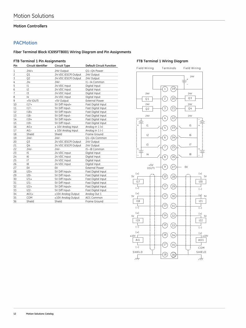
Fiber Terminal Block IC695FTB001 Wiring Diagram and Pin Assignments
FTB Terminal 1 Pin Assignments FTB Terminal 1 Wiring Diagram Pin Circuit Identifier Circuit Type Default Circuit Function
1 24V+ 24VOutput Q1—Q4Power2 Q1 24 VDC (ESCP) Output 24V Output3 Q2 24 VDC (ESCP) Output 24V Output4 24- 24V- I1—I4Common5 I1 24 VDC Input Digital Input6 I2 24 VDC Input Digital Input7 I3 24 VDC Input Digital Input8 I4 24 VDC Input Digital Input9 +5V (OUT) +5V Output External Power10 I17+ 5V Diff Input+ Fast Digital Input11 I17- 5V Diff Input- Fast Digital Input12 I18+ 5V Diff Input+ Fast Digital Input13 I18- 5V Diff Input- Fast Digital Input14 I19+ 5V Diff Input+ Fast Digital Input15 I19- 5V Diff Input- Fast Digital Input16 AI1+ ± 10V Analog Input Analog In 1 (+)17 AI1- ±10VAnalogInput AnalogIn1(–)18 Shield Shield Frame Ground19 24V- 24V- Q1—Q4Common20 Q3 24 VDC (ESCP) Output 24V Output21 Q4 24 VDC (ESCP) Output 24V Output22 24V- 24V- I5—I8Common23 I5 24 VDC Input Digital Input24 I6 24 VDC Input Digital Input25 I7 24 VDC Input Digital Input26 I8 24 VDC Input Digital Input27 0V 0V External Power28 I20+ 5V Diff Input+ Fast Digital Input29 I20- 5V Diff Input- Fast Digital Input30 I21+ 5V Diff Input+ Fast Digital Input31 I21- 5V Diff Input- Fast Digital Input32 I22+ 5V Diff Input+ Fast Digital Input33 I22- 5V Diff Input- Fast Digital Input34 AO1+ ±10V Analog Output Analog Out 135 COM ±10V Analog Output AO1 Common36 Shield Shield Frame Ground
F ield W iring T erm inals F ield W iring
1
3
5
7
9
11
13
15
17
19
2
4
6
8
10
12
14
16
18
27
–
+
Q 2
Q 1 Q 3
Q 4
20
21
22
23
24
25
26
28
29
30
31
32
33
34
35
36
24V
I2
I1
I4
I3
I5
I6
I7
I8
+5V ( OUT ) 0V
I17
I18
I19
A I1
I20
I21
I22
AO1
–
+
–
+
–
+
–
+
24V 24V
24V 24V
24V 24V
S HIE L D S HIE LD
5V
5V
5V
±10V
5V
5V
5V
±10V
( –)
(+)
( –)
(+)
( –)
(+)
( –)
(+)
( – )
(+)
( – )
(+)
( – )
(+)
C O M
(+)
Motion Solutions
GE Intelligent Platforms | www .ge-ip .com 13
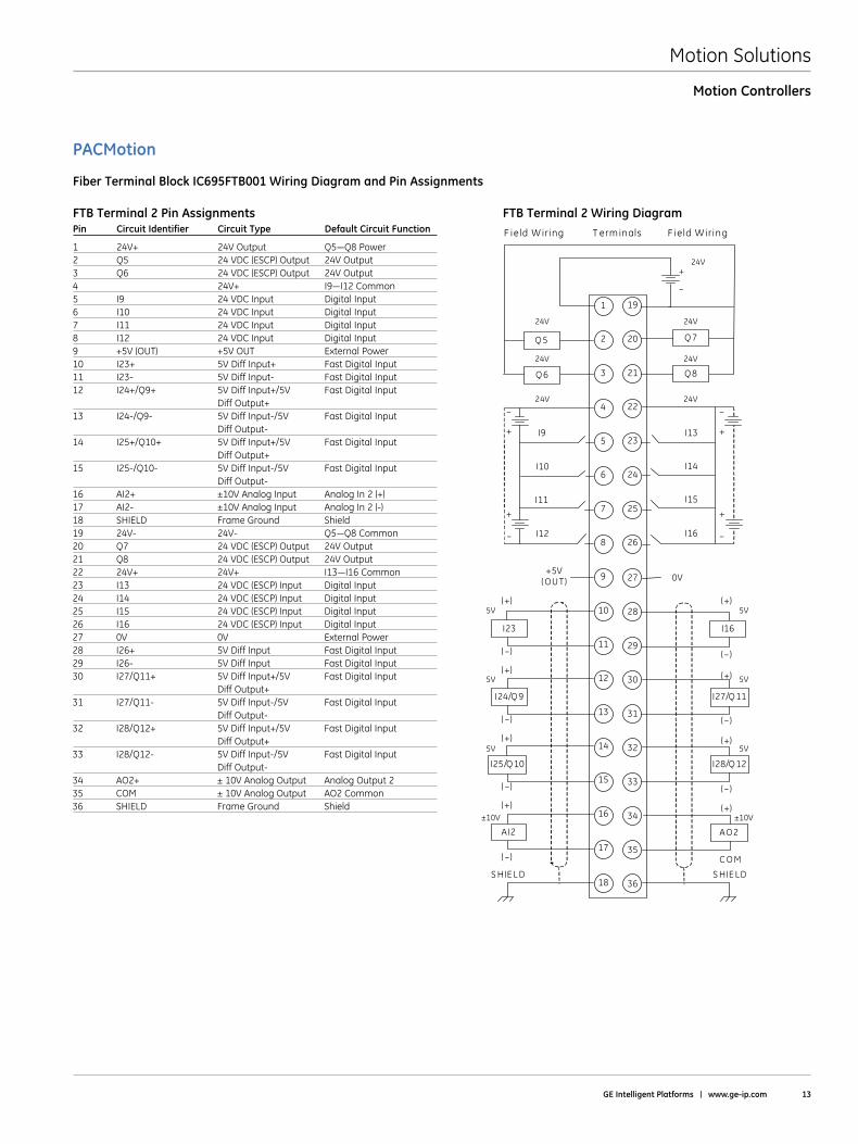
Pin Circuit Identifier Circuit Type Default Circuit Function
1 24V+ 24VOutput Q5—Q8Power2 Q5 24 VDC (ESCP) Output 24V Output3 Q6 24 VDC (ESCP) Output 24V Output4 24V+ I9—I12Common5 I9 24 VDC Input Digital Input6 I10 24 VDC Input Digital Input7 I11 24 VDC Input Digital Input8 I12 24 VDC Input Digital Input9 +5V (OUT) +5V OUT External Power10 I23+ 5V Diff Input+ Fast Digital Input11 I23- 5V Diff Input- Fast Digital Input12 I24+/Q9+ 5V Diff Input+/5V Fast Digital Input Diff Output+ 13 I24-/Q9- 5V Diff Input-/5V Fast Digital Input Diff Output- 14 I25+/Q10+ 5V Diff Input+/5V Fast Digital Input Diff Output+ 15 I25-/Q10- 5V Diff Input-/5V Fast Digital Input Diff Output- 16 AI2+ ±10V Analog Input Analog In 2 (+)17 AI2- ±10V Analog Input Analog In 2 (-)18 SHIELD Frame Ground Shield19 24V- 24V- Q5—Q8Common20 Q7 24 VDC (ESCP) Output 24V Output21 Q8 24 VDC (ESCP) Output 24V Output22 24V+ 24V+ I13—I16Common23 I13 24 VDC (ESCP) Input Digital Input24 I14 24 VDC (ESCP) Input Digital Input25 I15 24 VDC (ESCP) Input Digital Input26 I16 24 VDC (ESCP) Input Digital Input27 0V 0V External Power28 I26+ 5V Diff Input Fast Digital Input29 I26- 5V Diff Input Fast Digital Input30 I27/Q11+ 5V Diff Input+/5V Fast Digital Input Diff Output+ 31 I27/Q11- 5V Diff Input-/5V Fast Digital Input Diff Output- 32 I28/Q12+ 5V Diff Input+/5V Fast Digital Input Diff Output+ 33 I28/Q12- 5V Diff Input-/5V Fast Digital Input Diff Output- 34 AO2+ ± 10V Analog Output Analog Output 235 COM ± 10V Analog Output AO2 Common36 SHIELD Frame Ground Shield
PACMotion
Motion Controllers
Fiber Terminal Block IC695FTB001 Wiring Diagram and Pin Assignments
FTB Terminal 2 Pin Assignments FTB Terminal 2 Wiring Diagram F ield W iring T erm inals F ield W iring
1
3
5
7
9
11
13
15
17
19
2
4
6
8
10
12
14
16
18
27
–
+
Q 6
Q 5 Q 7
Q 8
20
21
22
23
24
25
26
28
29
30
31
32
33
34
35
36
24V
I10
I9
I12
I11
I13
I14
I15
I16
+5V ( OUT ) 0V
I23
I24/Q 9
I25/Q 10
A I2
I16
I27/Q 11
I28/Q 12
AO2
–
+
–
+
–
+
–
+
24V 24V
24V 24V
24V 24V
S HIE L D S HIE LD
5V
5V
5V
±10V
5V
5V
5V
±10V
( –)
(+)
( –)
(+)
( –)
(+)
( –)
(+)
( – )
(+)
( – )
(+)
( – )
(+)
C O M
(+)
Motion Solutions
14 Motion Solutions Catalog
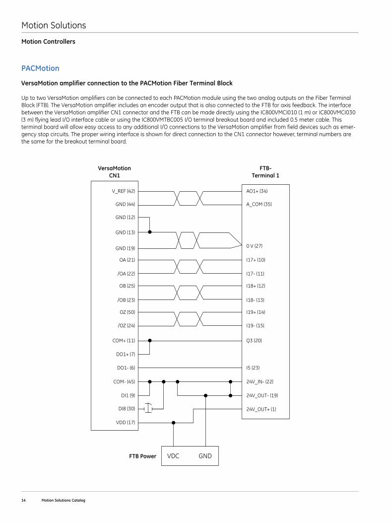
VersaMotion amplifier connection to the PACMotion Fiber Terminal Block
Up to two VersaMotion amplifiers can be connected to each PACMotion module using the two analog outputs on the Fiber Terminal Block (FTB) . The VersaMotion amplifier includes an encoder output that is also connected to the FTB for axis feedback . The interface between the VersaMotion amplifier CN1 connector and the FTB can be made directly using the IC800VMCI010 (1 m) or IC800VMCI030 (3 m) flying lead I/O interface cable or using the IC800VMTBC005 I/O terminal breakout board and included 0 .5 meter cable . This terminal board will allow easy access to any additional I/O connections to the VersaMotion amplifier from field devices such as emer-gency stop circuits . The proper wiring interface is shown for direct connection to the CN1 connector however, terminal numbers are the same for the breakout terminal board .
VersaMotionCN1
FTB-Terminal 1
FTB Power
V_REF (42)
GND (44)
GND (12)
GND (13)
GND (19)
OA (21)
/OA (22)
/OB (23)
OB (25)
OZ (50)
/OZ (24)
COM+ (11)
COM- (45)
DI1 (9)
DI8 (30)
VDD (17)
VDC GND
DO1+ (7)
DO1- (6)
AO1+ (34)
A_COM (35)
0 V (27)
I17+ (10)
I17- (11)
I18- (13)
I18+ (12)
I19+ (14)
I19- (15)
Q3 (20)
24V_IN- (22)
24V_OUT- (19)
24V_OUT+ (1)
I5 (23)
Motion Controllers
PACMotion
Motion Solutions
GE Intelligent Platforms | www .ge-ip .com 15
Motion Controllers
PACMotion
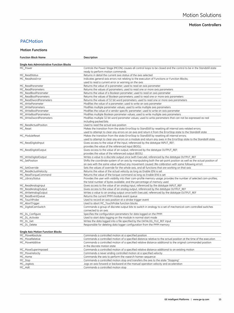
Motion Functions
Function Block Name Description Single Axis Administrative Function Blocks MC_Power Controls the Power Stage (MCON); causes all control loops to be closed and the control to be in the Standstill state ready to perform motion commandsMC_ReadStatus Returns in detail the current axis status of the axis selectedMC_ReadAxisError Indicates general axis errors not relating to the execution of Functions or Function Blocks; used to read a current error or warning on the axisMC_ReadParameter Returns the value of a parameter; used to read an axis parameterMC_ReadParameters Returns the values of parameters; used to read one or more axis parametersMC_ReadBoolParameter Returns the value of a Boolean parameter; used to read an axis parameterMC_ReadBoolParameters Returns the values of Boolean parameters; used to read one or more axis parametersMC_ReadDwordParameters Returns the values of 32 bit word parameters; used to read one or more axis parametersMC_WriteParameter Modifies the value of a parameter; used to write an axis parameterMC_WriteParameters Modifies multiple parameter values; used to write multiple axis parametersMC_WriteBoolParameter Modifies the value of a vendor specific parameter; used to write an axis parameterMC_WriteBoolParameters Modifies multiple Boolean parameter values; used to write multiple axis parametersMC_WriteDwordParameters Modifies multiple 32 bit word parameter values; used to write parameters that can not be expressed as real including packed bitsMC_ReadActualPosition Used to read the actual axis positionMC_Reset Makes the transition from the state ErrorStop to StandStill by resetting all internal axis-related errors; used to attempt to clear any errors on an axis and return it from the ErrorStop state to the Standstill stateMC_ModuleReset Makes the transition from the state ErrorStop to StandStill by resetting all internal errors; used to attempt to clear any errors on a module and return any axes in the ErrorStop state to the Standstill stateMC_ReadDigitalInput Gives access to the value of the input, referenced by the datatype INPUT_REF; provides the value of the referenced input (BOOL) .MC_ReadDigitalOutput Gives access to the value of an output, referenced by the datatype OUTPUT_REF; provides the value of the referenced output (BOOL)MC_WriteDigitalOutput Writes a value to a discrete output once (with Execute), referenced by the datatype OUTPUT_REFMC_SetPosition Shifts the coordinate system of an axis by manipulating both the set-point position as well as the actual position of an axis with the same value without any movement caused . (Re-calibration with same following error) . MC_SetOverride Sets the values of override for the whole axis, and all functions that are working on that axisMC_ReadActualVelocity Returns the value of the actual velocity as long as Enable (EN) is setMC_ReadTorqueCommand Returns the value of the torque command as long as Enable (EN) is setMC_LibraryStatus Provides the user with visibility into their cam-profile memory usage; provides the number of selected cam-profiles, the total number of bytes available, and the percentage of memory usedMC_ReadAnalogInput Gives access to the value of an analog input, referenced by the datatype INPUT_REFMC_ReadAnalogOutput Gives access to the value of an analog output, referenced by the datatype OUTPUT_REFMC_WriteAnalogOutput Writes a value to an analog output once (with Execute), referenced by the datatype OUTPUT_REFMC_ReadEventQueue Returns the current PMM module event queueMC_TouchProbe Used to record an axis position at a strobe trigger eventMC_AbortTrigger Used to abort MC_TouchProbe function blocksMC_DigitalCamSwitch Commands a group of discrete output bits to switch in analogy to a set of mechanical cam controlled switches connected to an axisMC_DL_Configure Specifies the configuration parameters for data logged on the PMMMC_DL_Activate Used to start data logging on the module in normal start modeMC_DL_Get Writes the data logged into a file specified by the DATALOG_FILE_REF inputMC_DL_Delete Responsible for deleting data logger configuration from the PMM memory Single Axis Motion Function Blocks MC_MoveAbsolute Commands a controlled motion at a specified positionMC_MoveRelative Commands a controlled motion of a specified distance relative to the actual position at the time of the executionMC_MoveAdditive Commands a controlled motion of a specified relative distance additional to the original commanded position in the discrete motion stateMC_MoveSuperimposed Commands a controlled motion of a specified relative distance additional to an existing motionMC_MoveVelocity Commands a never ending controlled motion at a specified velocityMC_Home Commands the axis to perform the «search home» sequenceMC_Stop Commands a controlled motion stop and transfers the axis to the state “Stopping”MC_JogAxis Jogs an axis forward or backward at the manual operation velocity and accelerationMC_Halt Commands a controlled motion stop
Motion Solutions
16 Motion Solutions Catalog
PACMotion
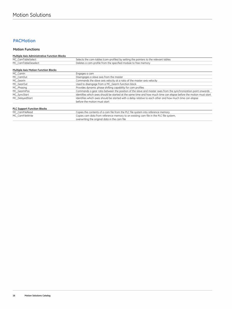
Motion Functions
Multiple Axis Administrative Function Blocks MC_CamTableSelect Selects the cam-tables (cam-profiles) by setting the pointers to the relevant tablesMC_CamTableDeselect Deletes a cam-profile from the specified module to free memory Multiple Axis Motion Function BlocksMC_CamIn Engages a camMC_CamOut Disengages a slave axis from the masterMC_GearIn Commands the slave axis velocity at a ratio of the master axis velocityMC_GearOut Used to disengage from a MC_GearIn function blockMC_Phasing Provides dynamic phase shifting capability for cam profilesMC_GearInPos Commands a gear ratio between the position of the slave and master axes from the synchronization point onwardsMC_SyncStart Identifies which axes should be started at the same time and how much time can elapse before the motion must startMC_DelayedStart Identifies which axes should be started with a delay relative to each other and how much time can elapse before the motion must start PLC Support Function BlocksMC_CamFileRead Copies the contents of a cam file from the PLC file system into reference memoryMC_CamFileWrite Copies cam data from reference memory to an existing cam file in the PLC file system, overwriting the original data in the cam file
Motion Solutions
GE Intelligent Platforms | www .ge-ip .com 17
Servo Amplifiers
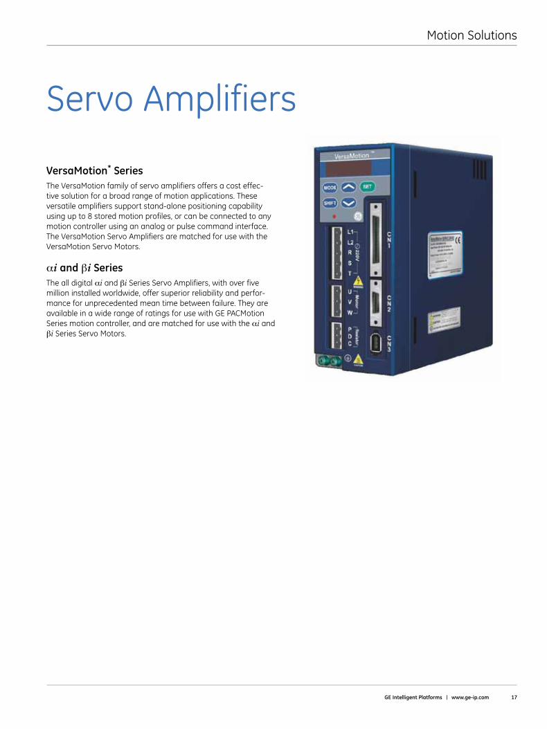
VersaMotion* SeriesThe VersaMotion family of servo amplifiers offers a cost effec-tive solution for a broad range of motion applications . These versatile amplifiers support stand-alone positioning capability using up to 8 stored motion profiles, or can be connected to any motion controller using an analog or pulse command interface . The VersaMotion Servo Amplifiers are matched for use with the VersaMotion Servo Motors .
αi and βi SeriesThe all digital αi and βi Series Servo Amplifiers, with over five million installed worldwide, offer superior reliability and perfor-mance for unprecedented mean time between failure . They are available in a wide range of ratings for use with GE PACMotion Series motion controller, and are matched for use with the αi and βi Series Servo Motors .
Motion Solutions
18 Motion Solutions Catalog
Servo Amplifiers
VersaMotion
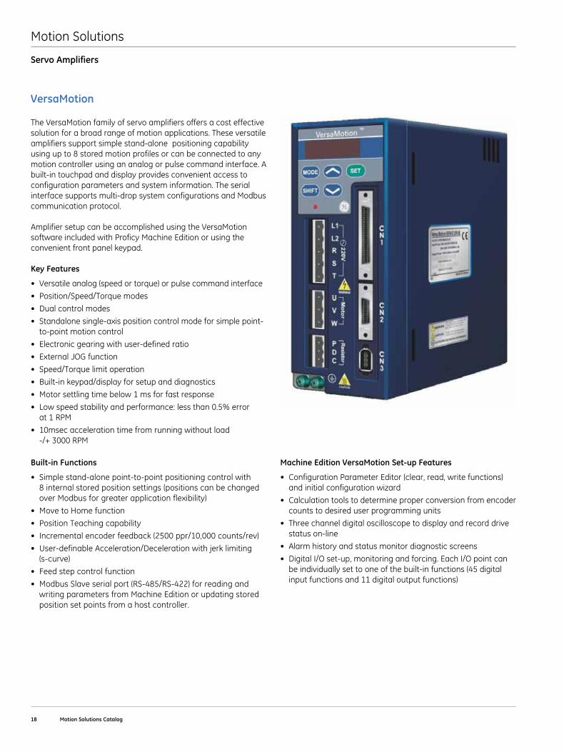
The VersaMotion family of servo amplifiers offers a cost effective solution for a broad range of motion applications . These versatile amplifiers support simple stand-alone positioning capability using up to 8 stored motion profiles or can be connected to any motion controller using an analog or pulse command interface . A built-in touchpad and display provides convenient access to configuration parameters and system information . The serial interface supports multi-drop system configurations and Modbus communication protocol .
Amplifier setup can be accomplished using the VersaMotion software included with Proficy Machine Edition or using the convenient front panel keypad .
Key Features
• Versatileanalog(speedortorque)orpulsecommandinterface
• Position/Speed/Torquemodes
• Dualcontrolmodes
• Standalonesingle-axispositioncontrolmodeforsimplepoint-to-point motion control
• Electronicgearingwithuser-definedratio
• ExternalJOGfunction
• Speed/Torquelimitoperation
• Built-inkeypad/displayforsetupanddiagnostics
• Motorsettlingtimebelow1msforfastresponse
• Lowspeedstabilityandperformance:lessthan0.5%error at 1 RPM
• 10msecaccelerationtimefromrunningwithoutload -/+ 3000 RPM
Built-in Functions
• Simplestand-alonepoint-to-pointpositioningcontrolwith 8 internal stored position settings (positions can be changed over Modbus for greater application flexibility)
• MovetoHomefunction
• PositionTeachingcapability
• Incrementalencoderfeedback(2500ppr/10,000counts/rev)
• User-definableAcceleration/Decelerationwithjerklimiting (s-curve)
• Feedstepcontrolfunction
• ModbusSlaveserialport(RS-485/RS-422)forreadingandwriting parameters from Machine Edition or updating stored position set points from a host controller .
Machine Edition VersaMotion Set-up Features
• ConfigurationParameterEditor(clear,read,writefunctions)and initial configuration wizard
• Calculationtoolstodetermineproperconversionfromencodercounts to desired user programming units
• Threechanneldigitaloscilloscopetodisplayandrecorddrivestatus on-line
• Alarmhistoryandstatusmonitordiagnosticscreens
• DigitalI/Oset-up,monitoringandforcing.EachI/Opointcanbe individually set to one of the built-in functions (45 digital input functions and 11 digital output functions)
Motion Solutions
GE Intelligent Platforms | www .ge-ip .com 19
Servo Amplifiers
VersaMotion
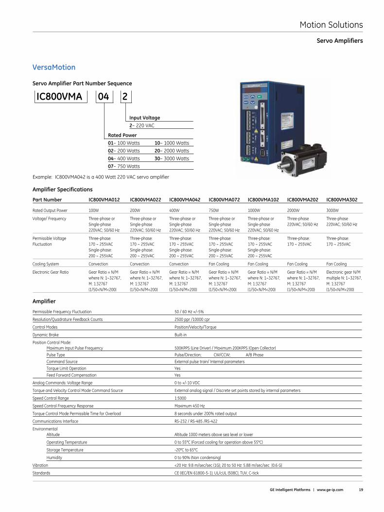
Servo Amplifier Part Number Sequence
IC800VMA 04 2
Input Voltage2–220VAC
Rated Power01–100Watts 10–1000Watts
02–200Watts 20–2000Watts
04–400Watts 30–3000Watts
07–750Watts
Example: IC800VMA042 is a 400 Watt 220 VAC servo amplifier
Amplifier Specifications
Part Number IC800VMA012 IC800VMA022 IC800VMA042 IC800VMA072 IC800VMA102 IC800VMA202 IC800VMA302
Rated Output Power 100W 200W 400W 750W 1000W 2000W 3000W
Voltage/ Frequency Three-phase or Three-phase or Three-phase or Three-phase or Three-phase or Three-phase Three-phase Single-phase Single-phase Single-phase Single-phase Single-phase 220VAC; 50/60 Hz 220VAC; 50/60 Hz 220VAC; 50/60 Hz 220VAC; 50/60 Hz 220VAC; 50/60 Hz 220VAC; 50/60 Hz 220VAC; 50/60 Hz
Permissible Voltage Three-phase: Three-phase: Three-phase: Three-phase: Three-phase: Three-phase: Three-phase: Fluctuation 170 ~ 255VAC 170 ~ 255VAC 170 ~ 255VAC 170 ~ 255VAC 170 ~ 255VAC 170 ~ 255VAC 170 ~ 255VAC Single-phase: Single-phase: Single-phase: Single-phase: Single-phase: 200 ~ 255VAC 200 ~ 255VAC 200 ~ 255VAC 200 ~ 255VAC 200 ~ 255VAC
Cooling System Convection Convection Convection Fan Cooling Fan Cooling Fan Cooling Fan Cooling
Electronic Gear Ratio Gear Ratio = N/M Gear Ratio = N/M Gear Ratio = N/M Gear Ratio = N/M Gear Ratio = N/M Gear Ratio = N/M Electronic gear N/M where N: 1~32767, where N: 1~32767, where N: 1~32767, where N: 1~32767, where N: 1~32767, where N: 1~32767, multiple N: 1~32767, M: 1:32767 M: 1:32767 M: 1:32767 M: 1:32767 M: 1:32767 M: 1:32767 M: 1:32767 (1/50<N/M<200) (1/50<N/M<200) (1/50<N/M<200) (1/50<N/M<200) (1/50<N/M<200) (1/50<N/M<200) (1/50<N/M<200)
Amplifier
PermissibleFrequencyFluctuation 50/60Hz+/-5%
Resolution/Quadrature Feedback Counts 2500 ppr /10000 cpr
Control Modes Position/Velocity/Torque
Dynamic Brake Built-in
Position Control Mode: Maximum Input Pulse Frequency 500KPPS (Line Driver) / Maximum 200KPPS (Open Collector)
Pulse Type Pulse/Direction; CW/CCW; A/B Phase
Command Source External pulse train/ Internal parameters
Torque Limit Operation Yes
Feed Forward Compensation Yes
Analog Commands: Voltage Range 0 to +/-10 VDC
Torque and Velocity Control Mode Command Source External analog signal / Discrete set points stored by internal parameters
Speed Control Range 1:5000
Speed Control Frequency Response Maximum 450 Hz
TorqueControlModePermissibleTimeforOverload 8secondsunder200%ratedoutput
Communications Interface RS-232 / RS-485 /RS-422
Environmental Altitude Altitude 1000 meters above sea level or lower
Operating Temperature 0 to 55°C (Forced cooling for operation above 55°C)
Storage Temperature -20°C to 65°C
Humidity 0to90%(Noncondensing)
Vibration <20 Hz: 9 .8 m/sec/sec (1G); 20 to 50 Hz: 5 .88 m/sec/sec (0 .6 G)
Standards CE (IEC/EN 61800-5-1), UL/cUL (508C), TUV, C-tick
Motion Solutions
20 Motion Solutions Catalog
Servo Amplifiers
VersaMotion
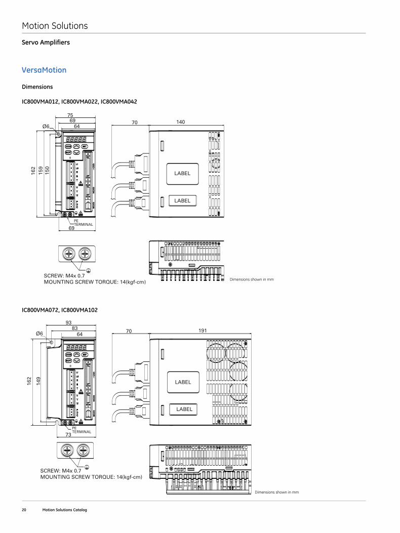
Dimensions
IC800VMA012, IC800VMA022, IC800VMA042
SCREW: M4x 0.7MOUNTING SCREW TORQUE: 14(kgf-cm)
75
Ø669
64
69
PE TERMINAL
162
159
150
70 140
LABEL
LABEL
SCREW: M4x 0.7MOUNTING SCREW TORQUE: 14(kgf-cm)
93
Ø683
64
73PE TERMINAL
162
149
70 191
LABEL
LABEL
IC800VMA072, IC800VMA102
Dimensions shown in mm
Dimensions shown in mm
Motion Solutions
GE Intelligent Platforms | www .ge-ip .com 21
Servo Amplifiers
VersaMotion
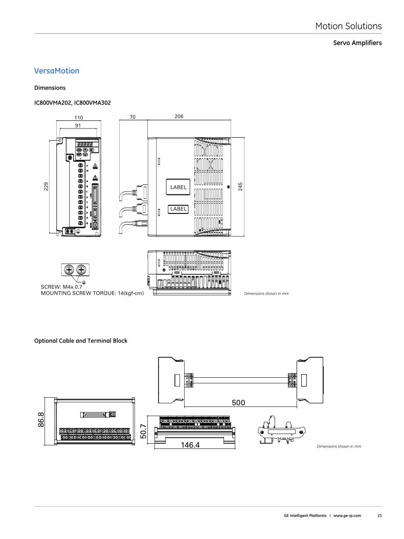
Dimensions
IC800VMA202, IC800VMA302
SCREW: M4x 0.7MOUNTING SCREW TORQUE: 14(kgf-cm)
110
91
229
245
70 206
LABEL
LABEL
Dimensions shown in mm
Dimensions shown in mm
Optional Cable and Terminal Block
146.4
50.786
.8
500
Motion Solutions
22 Motion Solutions Catalog
Servo Amplifiers
VersaMotion
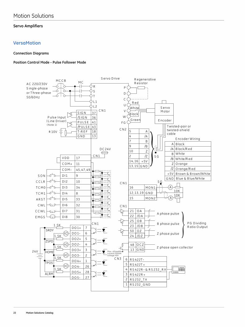
Connection Diagrams
Position Control Mode - Pulse Follower Mode
A C 220/230VS ingle-phas eor T hree-phas e50/60H z
S IG N/S IG NP U L S E/P U L S ET -R E FG N D
373641431813
R
S
T
L 2
L 1
5
4
7
9
10
2
14, 16
13, 15
P
D
C
U
V
W
F G
A
/A
B
/B
Z
/Z
+5V
G N D
C N 2
M C C B
C N 1
S G
M CS ervo D rive
P uls e Input( L ine D river)
R egenerativeR es is tor
S ervoM otor
E ncoder
R ed
W hite
B lack
G reen
T wis ted-pair ortwis ted-s hie ldcable
V D D
C O M +
C O M -
D I1
D I2
D I3
D I4
D I5
D I6
D I7
D I8
17
11
45, 47, 49
9
10
34
8
33
32
31
30
D O 1+
D O 1-
D O 2+
D O 2-
D O 3+
D O 3-
D O 4+
D O 4-
D O 5+
D O 5-
7
6
5
4
3
2
1
26
28
27
24V
1. 5K
1. 5K
1. 5K
1. 5K
1. 5K
SRDY
ZSPD
HOME
ALRM
D C 24V
C N 1
C N 1
TPOS
S O N
C C L R
A R S T
C W L
C C W L
E M G S
T C M 0
T C M 1
6
5
4
3
2
1
R S 422T -
R S 422T +
R S 422R - & R S 232_ R X
R S 422R +
R S 232_ T X
R S 232_ G N D
C N 3
( Note 1)
10V
16
12, 13, 19
15
M O N 1
G N D
M O N 2
10K10K
S G
A
A
C N 1
21
22
25
23
50
24
O A
/O A
O B
/O B
O Z
/O Z
C N 1
A phas e puls e
B phas e puls e
Z phas e puls e
P G D ividingR atio O utput
M ax. allowablecurrent 200mAvoltage 40V
48
13
O C Z
G N DZ phas e open collector
A
/A
B
/B
Z
/Z
+5V
G N D
B lack
B lack/R ed
W hite
W hite/R ed
O range
O range/R ed
B rown & B rown/W hite
B lue & B lue/W hite
E ncoder W iring
PT STANDARD CONNECTION
Motion Solutions
GE Intelligent Platforms | www .ge-ip .com 23
VersaMotion
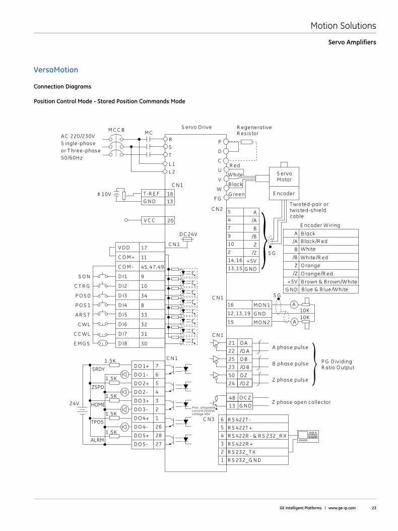
Connection Diagrams
Position Control Mode - Stored Position Commands Mode
T -R E FG N D
1813
R
S
T
L 2
L 1
M C C B
C N 1
M C
V D D
C O M +
C O M -
D I1
D I2
D I3
D I4
D I5
D I6
D I7
D I8
17
11
45, 47, 49
9
10
34
8
33
32
31
30
S O N
C T R G
P O S 0
P O S 1
A R S T
C WL
C C WL
E M G S
D O 1+
D O 1-
D O 2+
D O 2-
D O 3+
D O 3-
D O 4+
D O 4-
D O 5+
D O 5-
7
6
5
4
3
2
1
26
28
27
24V
1. 5K
1. 5K
1. 5K
1. 5K
1. 5K
D C 24V
C N 1
C N 1
A C 220/230VS ingle-phas eor T hree-phas e50/60H z
S ervo D rive R egenerativeR es is tor
S ervoM otor
E ncoder
R ed
W hite
B lack
G reen
V C C 20
5
4
7
9
10
2
14, 16
13, 15
A
/A
B
/B
Z
/Z
+5V
G N D
C N 2
S G
T wis ted-pair ortwis ted-s hie ldcable
6
5
4
3
2
1
R S 422T -
R S 422T +
R S 422R - & R S 232_R X
R S 422R +
R S 232_ T X
R S 232_ G N D
C N3
10V
P
D
C
U
V
W
F G
16
12, 13, 19
15
M O N 1
G N D
M O N 2
10K10K
S G
A
A
C N 1
21
22
25
23
50
24
O A
/O A
O B
/O B
O Z
/O Z
C N 1
A phas e puls e
B phas e puls e
Z phas e puls e
P G D ividingR atio O utput
48
13
O C Z
G N DZ phas e open collector
M ax. allowablecurrent 200mAvoltage 40V
A
/A
B
/B
Z
/Z
+5V
G N D
B lack
B lack/R ed
W hite
W hite/R ed
O range
O range/R ed
B rown & B rown/W hite
B lue & B lue/W hite
E ncoder W iring
PR STANDARD CONNECTION
SRDY
ZSPD
HOME
ALRM
TPOS
Servo Amplifiers
Motion Solutions
24 Motion Solutions Catalog
VersaMotion
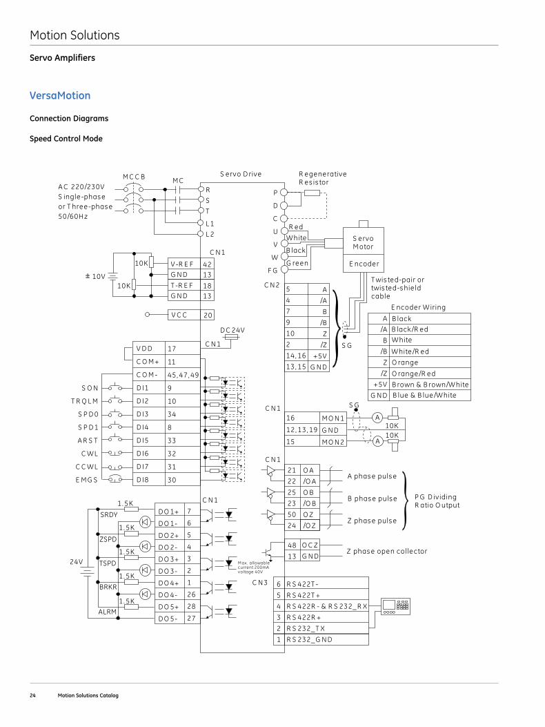
Connection Diagrams
Speed Control Mode
V-R E FG N D
4213
R
S
T
L 2
L 1
M C C B
C N 1
M C
V D D
C O M +
C O M -
D I1
D I2
D I3
D I4
D I5
D I6
D I7
D I8
17
11
45, 47, 49
9
10
34
8
33
32
31
30
S O N
T R Q L M
S P D 0
S P D 1
A R S T
C WL
C C WL
E M G S
D O 1+
D O 1-
D O 2+
D O 2-
D O 3+
D O 3-
D O 4+
D O 4-
D O 5+
D O 5-
7
6
5
4
3
2
1
26
28
27
24V
1. 5K
1. 5K
1. 5K
1. 5K
1. 5K
SRDY
ZSPD
TSPD
ALRM
D C 24V
C N 1
C N 1
BRKR
T -R E FG N D
1813
10K
10K
A C 220/230VS ingle-phas eor T hree-phas e50/60H z
S ervo D rive
V C C 20
5
4
7
9
10
2
14, 16
13, 15
P
D
C
U
V
W
F G
A
/A
B
/B
Z
/Z
+5V
G N D
C N 2
S G
R egenerativeR es is tor
S ervoM otor
E ncoder
R ed
W hite
B lack
G reen
T wis ted-pair ortwis ted-s hie ldcable
6
5
4
3
2
1
R S 422T -
R S 422T +
R S 422R - & R S 232_ R X
R S 422R +
R S 232_ T X
R S 232_ G N D
C N 3
10V
16
12, 13, 19
15
M O N 1
G N D
M O N 2
10K10K
S G
A
A
C N 1
21
22
25
23
50
24
O A
/O A
O B
/O B
O Z
/O Z
C N 1
A phas e puls e
B phas e puls e
Z phas e puls e
P G D ividingR atio O utput
48
13
O C Z
G N DZ phas e open collector
M ax. allowablecurrent 200mAvoltage 40V
A
/A
B
/B
Z
/Z
+5V
G N D
B lack
B lack/R ed
W hite
W hite/R ed
O range
O range/R ed
B rown & B rown/W hite
B lue & B lue/W hite
E ncoder W iring
S STANDARD CONNECTION
Servo Amplifiers
Motion Solutions
GE Intelligent Platforms | www .ge-ip .com 25
Servo Amplifiers
VersaMotion
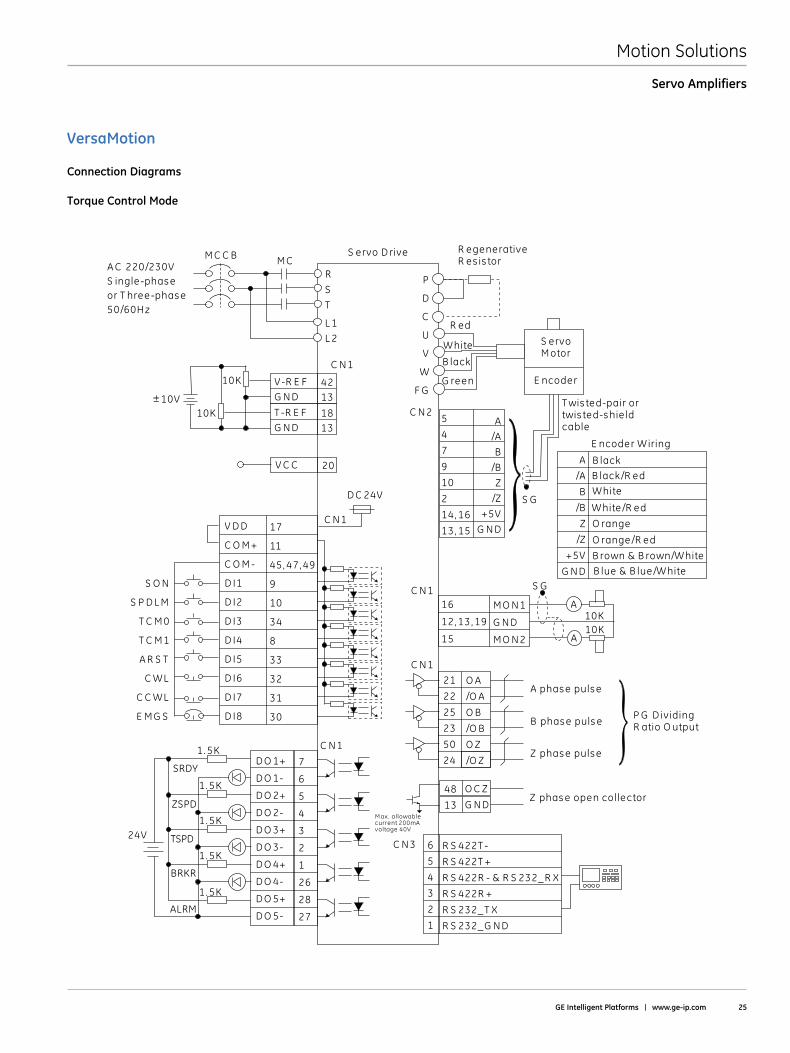
Connection Diagrams
Torque Control Mode
V-R E FG N D
4213
R
S
T
L 2
L 1
M C C B
C N 1
M C
V D D
C O M +
C O M -
D I1
D I2
D I3
D I4
D I5
D I6
D I7
D I8
17
11
45, 47, 49
9
10
34
8
33
32
31
30
S O N
S P D L M
T C M 0
T C M 1
A R S T
C WL
C C WL
E M G S
D O 1+
D O 1-
D O 2+
D O 2-
D O 3+
D O 3-
D O 4+
D O 4-
D O 5+
D O 5-
7
6
5
4
3
2
1
26
28
27
24V
1. 5K
1. 5K
1. 5K
1. 5K
1. 5K
D C 24V
C N 1
C N 1
T -R E FG N D
1813
10K
10K
A C 220/230VS ingle-phas eor T hree-phas e50/60H z
S ervo D rive
V C C 20
5
4
7
9
10
2
14, 16
13, 15
P
D
C
U
V
W
F G
A
/A
B
/B
Z
/Z
+5V
G N D
C N 2
S G
R egenerativeR es is tor
S ervoM otor
E ncoder
R ed
W hite
B lack
G reen
T wis ted-pair ortwis ted-s hie ldcable
6
5
4
3
2
1
R S 422T -
R S 422T +
R S 422R - & R S 232_ R X
R S 422R +
R S 232_ T X
R S 232_ G N D
C N 3
10V
16
12, 13, 19
15
M O N 1
G N D
M O N 2
10K10K
S G
A
A
C N 1
21
22
25
23
50
24
O A
/O A
O B
/O B
O Z
/O Z
C N 1
A phas e puls e
B phas e puls e
Z phas e puls e
P G D ividingR atio O utput
48
13
O C Z
G N DZ phas e open collector
M ax. allowablecurrent 200mAvoltage 40V
A
/A
B
/B
Z
/Z
+5V
G N D
B lack
B lack/R ed
W hite
W hite/R ed
O range
O range/R ed
B rown & B rown/W hite
B lue & B lue/W hite
E ncoder W iring
T STANDARD CONNECTION
SRDY
ZSPD
TSPD
ALRM
BRKR
Motion Solutions
26 Motion Solutions Catalog
Servo Amplifiers
VersaMotion
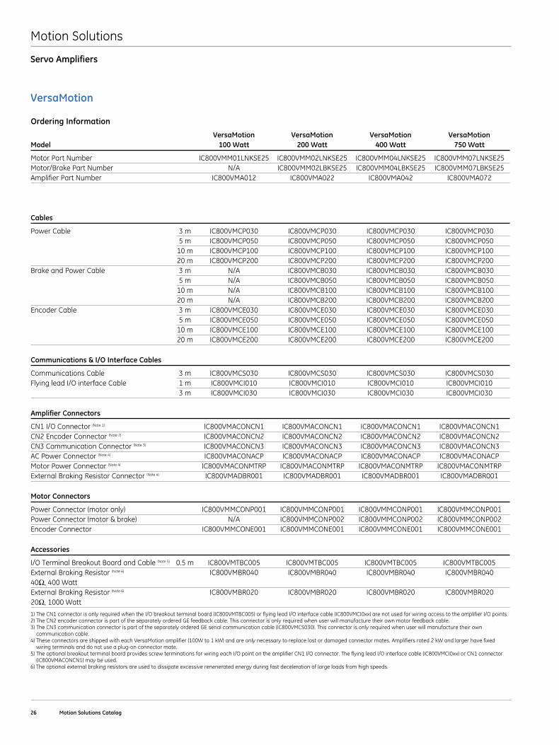
Ordering Information
VersaMotion VersaMotion VersaMotion VersaMotion Model 100 Watt 200 Watt 400 Watt 750 Watt
Motor Part Number IC800VMM01LNKSE25 IC800VMM02LNKSE25 IC800VMM04LNKSE25 IC800VMM07LNKSE25Motor/Brake Part Number N/A IC800VMM02LBKSE25 IC800VMM04LBKSE25 IC800VMM07LBKSE25Amplifier Part Number IC800VMA012 IC800VMA022 IC800VMA042 IC800VMA072
Cables
Power Cable 3 m IC800VMCP030 IC800VMCP030 IC800VMCP030 IC800VMCP030 5 m IC800VMCP050 IC800VMCP050 IC800VMCP050 IC800VMCP050 10 m IC800VMCP100 IC800VMCP100 IC800VMCP100 IC800VMCP100 20 m IC800VMCP200 IC800VMCP200 IC800VMCP200 IC800VMCP200Brake and Power Cable 3 m N/A IC800VMCB030 IC800VMCB030 IC800VMCB030 5 m N/A IC800VMCB050 IC800VMCB050 IC800VMCB050 10 m N/A IC800VMCB100 IC800VMCB100 IC800VMCB100 20 m N/A IC800VMCB200 IC800VMCB200 IC800VMCB200Encoder Cable 3 m IC800VMCE030 IC800VMCE030 IC800VMCE030 IC800VMCE030 5 m IC800VMCE050 IC800VMCE050 IC800VMCE050 IC800VMCE050 10 m IC800VMCE100 IC800VMCE100 IC800VMCE100 IC800VMCE100 20 m IC800VMCE200 IC800VMCE200 IC800VMCE200 IC800VMCE200
Communications & I/O Interface Cables
Communications Cable 3 m IC800VMCS030 IC800VMCS030 IC800VMCS030 IC800VMCS030Flying lead I/O interface Cable 1 m IC800VMCI010 IC800VMCI010 IC800VMCI010 IC800VMCI010 3 m IC800VMCI030 IC800VMCI030 IC800VMCI030 IC800VMCI030
Amplifier Connectors
CN1 I/O Connector (Note 1) IC800VMACONCN1 IC800VMACONCN1 IC800VMACONCN1 IC800VMACONCN1CN2 Encoder Connector (Note 2) IC800VMACONCN2 IC800VMACONCN2 IC800VMACONCN2 IC800VMACONCN2CN3 Communication Connector (Note 3) IC800VMACONCN3 IC800VMACONCN3 IC800VMACONCN3 IC800VMACONCN3AC Power Connector (Note 4) IC800VMACONACP IC800VMACONACP IC800VMACONACP IC800VMACONACPMotor Power Connector (Note 4) IC800VMACONMTRP IC800VMACONMTRP IC800VMACONMTRP IC800VMACONMTRPExternal Braking Resistor Connector (Note 4) IC800VMADBR001 IC800VMADBR001 IC800VMADBR001 IC800VMADBR001
Motor Connectors
Power Connector (motor only) IC800VMMCONP001 IC800VMMCONP001 IC800VMMCONP001 IC800VMMCONP001Power Connector (motor & brake) N/A IC800VMMCONP002 IC800VMMCONP002 IC800VMMCONP002Encoder Connector IC800VMMCONE001 IC800VMMCONE001 IC800VMMCONE001 IC800VMMCONE001
Accessories
I/O Terminal Breakout Board and Cable (Note 5) 0 .5 m IC800VMTBC005 IC800VMTBC005 IC800VMTBC005 IC800VMTBC005External Braking Resistor (Note 6) IC800VMBR040 IC800VMBR040 IC800VMBR040 IC800VMBR040 40Ω, 400 Watt External Braking Resistor (Note 6) IC800VMBR020 IC800VMBR020 IC800VMBR020 IC800VMBR020 20Ω, 1000 Watt
1) The CN1 connector is only required when the I/O breakout terminal board (IC800VMTBC005) or flying lead I/O interface cable (IC800VMCI0xx) are not used for wiring access to the amplifier I/O points . 2) The CN2 encoder connector is part of the separately ordered GE feedback cable . This connector is only required when user will manufacture their own motor feedback cable . 3) The CN3 communication connector is part of the separately ordered GE serial communication cable (IC800VMCS030) . This connector is only required when user will manufacture their own communication cable . 4) These connectors are shipped with each VersaMotion amplifier (100W to 1 kW) and are only necessary to replace lost or damaged connector mates . Amplifiers rated 2 kW and larger have fixed wiring terminals and do not use a plug-on connector mate . 5) The optional breakout terminal board provides screw terminations for wiring each I/O point on the amplifier CN1 I/O connector . The flying lead I/O interface cable (IC800VMCI0xx) or CN1 connector (IC800VMACONCN1) may be used . 6) The optional external braking resistors are used to dissipate excessive renenerated energy during fast deceleration of large loads from high speeds .
Motion Solutions
GE Intelligent Platforms | www .ge-ip .com 27
Servo Amplifiers
VersaMotion
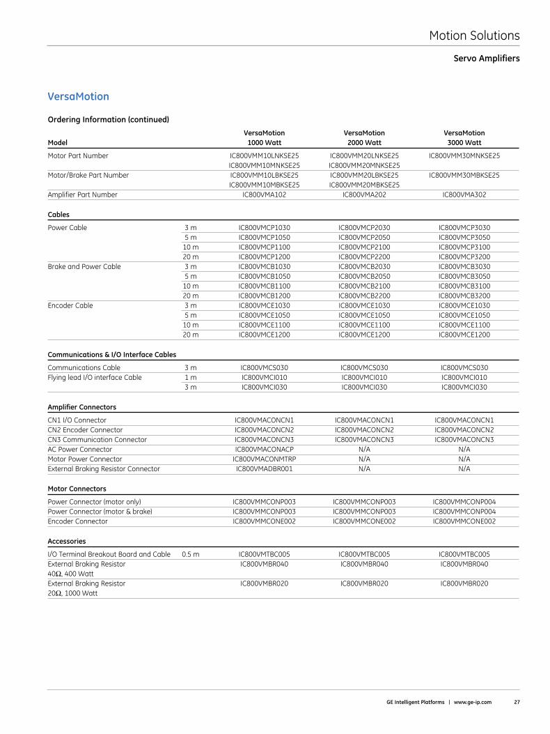
Ordering Information (continued)
VersaMotion VersaMotion VersaMotion Model 1000 Watt 2000 Watt 3000 Watt
Motor Part Number IC800VMM10LNKSE25 IC800VMM20LNKSE25 IC800VMM30MNKSE25 IC800VMM10MNKSE25 IC800VMM20MNKSE25Motor/Brake Part Number IC800VMM10LBKSE25 IC800VMM20LBKSE25 IC800VMM30MBKSE25 IC800VMM10MBKSE25 IC800VMM20MBKSE25Amplifier Part Number IC800VMA102 IC800VMA202 IC800VMA302
Cables
Power Cable 3 m IC800VMCP1030 IC800VMCP2030 IC800VMCP3030 5 m IC800VMCP1050 IC800VMCP2050 IC800VMCP3050 10 m IC800VMCP1100 IC800VMCP2100 IC800VMCP3100 20 m IC800VMCP1200 IC800VMCP2200 IC800VMCP3200Brake and Power Cable 3 m IC800VMCB1030 IC800VMCB2030 IC800VMCB3030 5 m IC800VMCB1050 IC800VMCB2050 IC800VMCB3050 10 m IC800VMCB1100 IC800VMCB2100 IC800VMCB3100 20 m IC800VMCB1200 IC800VMCB2200 IC800VMCB3200Encoder Cable 3 m IC800VMCE1030 IC800VMCE1030 IC800VMCE1030 5 m IC800VMCE1050 IC800VMCE1050 IC800VMCE1050 10 m IC800VMCE1100 IC800VMCE1100 IC800VMCE1100 20 m IC800VMCE1200 IC800VMCE1200 IC800VMCE1200
Communications & I/O Interface Cables
Communications Cable 3 m IC800VMCS030 IC800VMCS030 IC800VMCS030Flying lead I/O interface Cable 1 m IC800VMCI010 IC800VMCI010 IC800VMCI010 3 m IC800VMCI030 IC800VMCI030 IC800VMCI030
Amplifier Connectors
CN1 I/O Connector IC800VMACONCN1 IC800VMACONCN1 IC800VMACONCN1CN2 Encoder Connector IC800VMACONCN2 IC800VMACONCN2 IC800VMACONCN2CN3 Communication Connector IC800VMACONCN3 IC800VMACONCN3 IC800VMACONCN3AC Power Connector IC800VMACONACP N/A N/AMotor Power Connector IC800VMACONMTRP N/A N/AExternal Braking Resistor Connector IC800VMADBR001 N/A N/A
Motor Connectors
Power Connector (motor only) IC800VMMCONP003 IC800VMMCONP003 IC800VMMCONP004Power Connector (motor & brake) IC800VMMCONP003 IC800VMMCONP003 IC800VMMCONP004Encoder Connector IC800VMMCONE002 IC800VMMCONE002 IC800VMMCONE002
Accessories
I/O Terminal Breakout Board and Cable 0 .5 m IC800VMTBC005 IC800VMTBC005 IC800VMTBC005External Braking Resistor IC800VMBR040 IC800VMBR040 IC800VMBR040 40Ω, 400 Watt External Braking Resistor IC800VMBR020 IC800VMBR020 IC800VMBR020 20Ω, 1000 Watt
Motion Solutions
28 Motion Solutions Catalog
VersaMotion
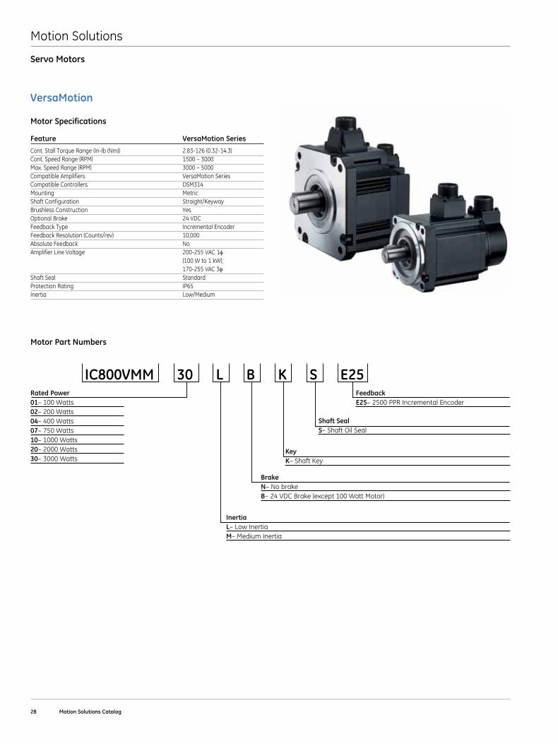
Motor Specifications
Servo Motors
Feature VersaMotion Series
Cont . Stall Torque Range (In-lb (Nm)) 2 .83-126 (0 .32-14 .3)Cont.SpeedRange(RPM) 1500–3000Max.SpeedRange(RPM) 3000–5000Compatible Amplifiers VersaMotion SeriesCompatible Controllers DSM314Mounting MetricShaft Configuration Straight/KeywayBrushless Construction YesOptional Brake 24 VDCFeedback Type Incremental EncoderFeedback Resolution (Counts/rev) 10,000Absolute Feedback NoAmplifier Line Voltage 200-255 VAC 1φ (100 W to 1 kW); 170-255 VAC 3φShaft Seal StandardProtection Rating IP65Inertia Low/Medium
Motor Part Numbers
IC800VMM 30 L B K S E25FeedbackE25–2500PPRIncrementalEncoder
Rated Power01–100Watts02–200Watts04–400Watts07–750Watts10–1000Watts20–2000Watts30–3000Watts
Shaft SealS–ShaftOilSeal
KeyK–ShaftKey
BrakeN–NobrakeB–24VDCBrake(except100WattMotor)
InertiaL–LowInertiaM–MediumInertia
Motion Solutions
GE Intelligent Platforms | www .ge-ip .com 29
Servo Motors
VersaMotion Servo Motors
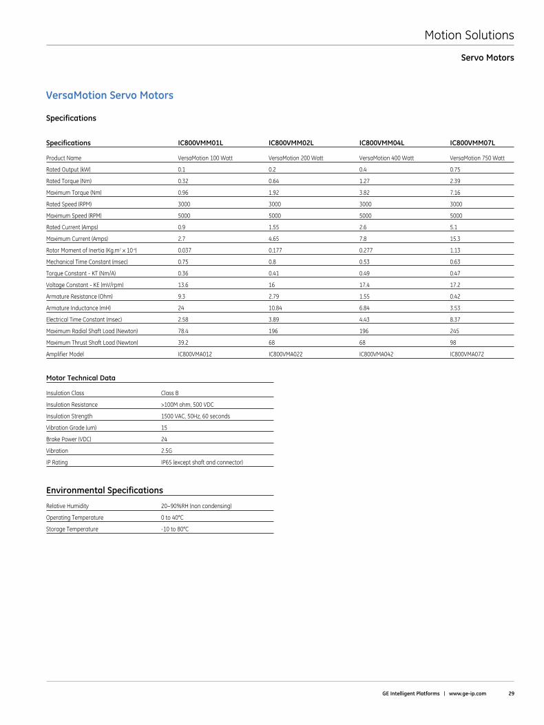
Specifications
Specifications IC800VMM01L IC800VMM02L IC800VMM04L IC800VMM07L
Product Name VersaMotion 100 Watt VersaMotion 200 Watt VersaMotion 400 Watt VersaMotion 750 Watt
Rated Output (kW) 0 .1 0 .2 0 .4 0 .75
Rated Torque (Nm) 0 .32 0 .64 1 .27 2 .39
Maximum Torque (Nm) 0 .96 1 .92 3 .82 7 .16
Rated Speed (RPM) 3000 3000 3000 3000
Maximum Speed (RPM) 5000 5000 5000 5000
Rated Current (Amps) 0 .9 1 .55 2 .6 5 .1
Maximum Current (Amps) 2 .7 4 .65 7 .8 15 .3
Rotor Moment of Inertia (Kg .m2 x 10-4) 0 .037 0 .177 0 .277 1 .13
Mechanical Time Constant (msec) 0 .75 0 .8 0 .53 0 .63
Torque Constant - KT (Nm/A) 0 .36 0 .41 0 .49 0 .47
Voltage Constant - KE (mV/rpm) 13 .6 16 17 .4 17 .2
Armature Resistance (Ohm) 9 .3 2 .79 1 .55 0 .42
Armature Inductance (mH) 24 10 .84 6 .84 3 .53
Electrical Time Constant (msec) 2 .58 3 .89 4 .43 8 .37
Maximum Radial Shaft Load (Newton) 78 .4 196 196 245
Maximum Thrust Shaft Load (Newton) 39 .2 68 68 98
Amplifier Model IC800VMA012 IC800VMA022 IC800VMA042 IC800VMA072
Motor Technical Data
Insulation Class Class B
Insulation Resistance >100M ohm, 500 VDC
Insulation Strength 1500 VAC, 50Hz, 60 seconds
Vibration Grade (um) 15
Brake Power (VDC) 24
Vibration 2 .5G
IP Rating IP65 (except shaft and connector)
Environmental Specifications
RelativeHumidity 20~90%RH(noncondensing)
Operating Temperature 0 to 40°C
Storage Temperature -10 to 80°C
Motion Solutions
30 Motion Solutions Catalog
Servo Motors
VersaMotion Servo Motors
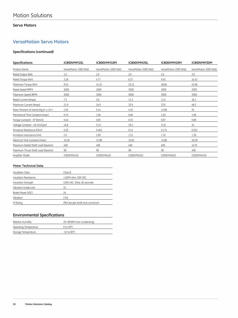
Specifications (continued)
Specifications IC800VMM10L IC800VMM10M IC800VMM20L IC800VMM20M IC800VMM30M
Product Name VersaMotion 1000 Watt VersaMotion 1000 Watt VersaMotion 2000 Watt VersaMotion 2000 Watt VersaMotion 3000 Watt
Rated Output (kW) 1 .0 1 .0 2 .0 2 .0 3 .0
Rated Torque (Nm) 3 .18 4 .77 6 .37 9 .55 14 .32
Maximum Torque (Nm) 9 .54 14 .32 19 .11 28 .66 42 .96
Rated Speed (RPM) 3000 2000 3000 2000 2000
Maximum Speed (RPM) 5000 3000 5000 3000 3000
Rated Current (Amps) 7 .3 5 .6 11 .3 11 .0 16 .1
Maximum Current (Amps) 21 .9 24 .9 33 .9 33 .0 48 .3
Rotor Moment of Inertia (Kg .m2 x 10-4) 2 .65 9 .14 4 .45 15 .88 55
Mechanical Time Constant (msec) 0 .74 1 .64 0 .66 1 .05 1 .06
Torque Constant - KT (Nm/A) 0 .44 0 .85 0 .53 0 .87 0 .89
Voltage Constant - KE (mV/rpm) 16 .8 31 .9 19 .2 31 .8 32
Armature Resistance (Ohm) 0 .20 0 .465 0 .14 0 .174 0 .052
Armature Inductance (mH) 2 .0 5 .99 1 .53 2 .76 1 .38
Electrical Time Constant (msec) 10 .26 12 .88 10 .63 15 .86 26 .39
Maximum Radial Shaft Load (Newton) 490 490 490 490 1470
Maximum Thrust Shaft Load (Newton) 98 98 98 98 490
Amplifier Model IC800VMA102 IC800VMA102 IC800VMA202 IC800VMA202 IC800VMA302
Motor Technical Data
Insulation Class Class B
Insulation Resistance >100M ohm, 500 VDC
Insulation Strength 1500 VAC, 50Hz, 60 seconds
Vibration Grade (um) 15
Brake Power (VDC) 24
Vibration 2 .5G
IP Rating IP65 (except shaft and connector)
Environmental Specifications
RelativeHumidity 20~90%RH(noncondensing)
Operating Temperature 0 to 40°C
Storage Temperature -10 to 80°C
Motion Solutions
GE Intelligent Platforms | www .ge-ip .com 31
Servo Motors
VersaMotion Servo Motors
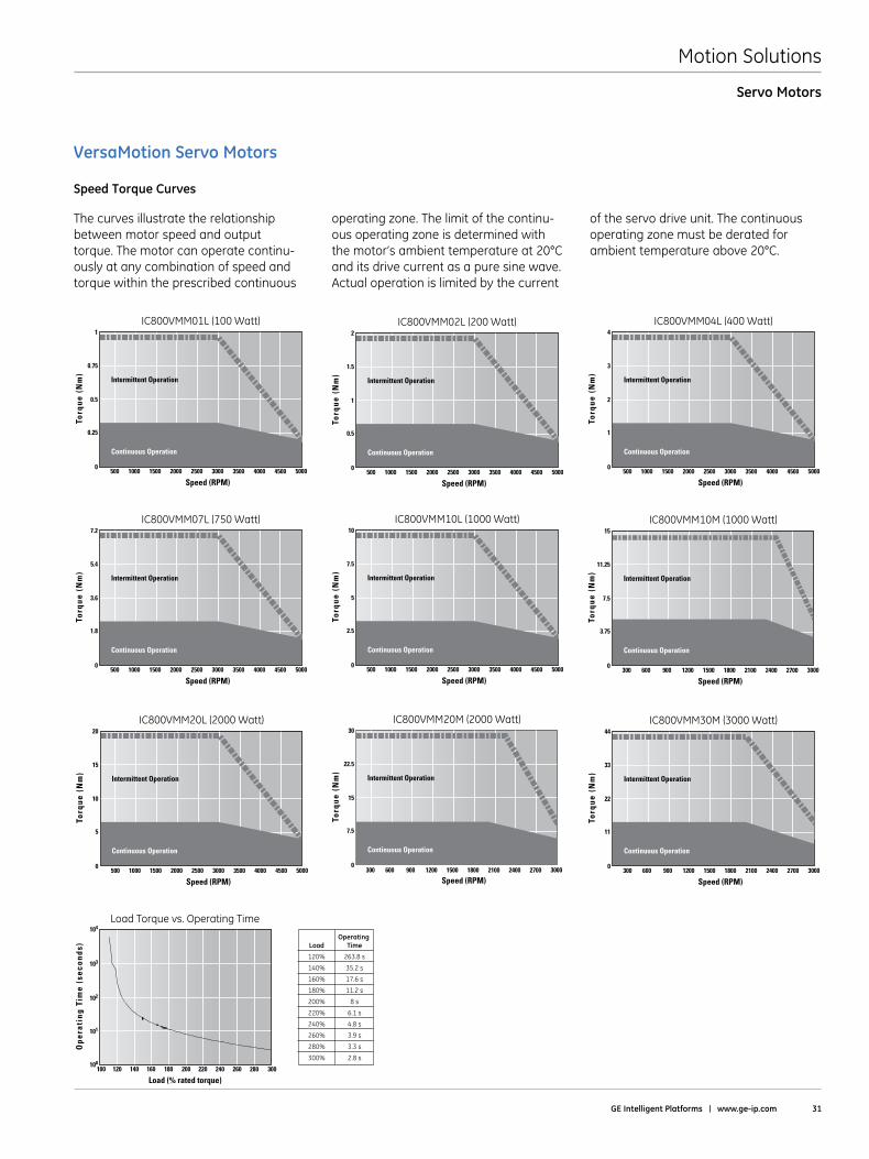
Speed Torque Curves
Torq
ue (
Nm
)IC800VMM02L (200 Watt)
Speed (RPM)
0
0.5
2
1
1.5
4500 500040003500300025001500 20001000500
Continuous Operation
Intermittent Operation
Torq
ue (
Nm
)
IC800VMM30M (3000 Watt)
Speed (RPM)
0
11
44
22
33
2700 30002400210018001500900 1200600300
Continuous Operation
Intermittent Operation
Ope
rati
ng T
ime
(sec
onds
)
Load Torque vs. Operating Time
Load (% rated torque)
101
102
103
104
280 300260240220200160 180140120100
100
Operating Load Time
120% 263.8 s
140% 35.2 s
160% 17.6 s
180% 11.2 s
200% 8 s
220% 6.1 s
240% 4.8 s
260% 3.9 s
280% 3.3 s
300% 2.8 s
Torq
ue (
Nm
)
IC800VMM10M (1000 Watt)
Speed (RPM)
0
3.75
15
7.5
11.25
Continuous Operation
Intermittent Operation
2700 30002400210018001500900 1200600300
Torq
ue (
Nm
)
IC800VMM04L (400 Watt)
Speed (RPM)
0
1
4
2
3
4500 500040003500300025001500 20001000500
Continuous Operation
Intermittent Operation
Torq
ue (
Nm
)
IC800VMM07L (750 Watt)
Speed (RPM)
0
1.8
7.2
3.6
5.4
4500 500040003500300025001500 20001000500
Continuous Operation
Intermittent Operation
Torq
ue (
Nm
)
IC800VMM01L (100 Watt)
Speed (RPM)
0
0.25
1
0.5
0.75
4500 500040003500300025001500 20001000500
Continuous Operation
Intermittent Operation
Torq
ue (
Nm
)
IC800VMM10L (1000 Watt)
Speed (RPM)
0
2.5
10
5
7.5
4500 500040003500300025001500 20001000500
Continuous Operation
Intermittent Operation
The curves illustrate the relationship between motor speed and output torque . The motor can operate continu-ously at any combination of speed and torque within the prescribed continuous
operating zone . The limit of the continu-ous operating zone is determined with the motor’s ambient temperature at 20°C and its drive current as a pure sine wave . Actual operation is limited by the current
of the servo drive unit . The continuous operating zone must be derated for ambient temperature above 20°C .
IC800VMM20M (2000 Watt)
Torq
ue (
Nm
)
Speed (RPM)
0
7.5
30
15
22.5
Continuous Operation
Intermittent Operation
2700 30002400210018001500900 1200600300
IC800VMM20L (2000 Watt)
Torq
ue (
Nm
)
Speed (RPM)
0
5
20
10
15
4500 500040003500300025001500 20001000500
Continuous Operation
Intermittent Operation
Motion Solutions
32 Motion Solutions Catalog
Servo Motors
VersaMotion Servo Motors
Dimensions
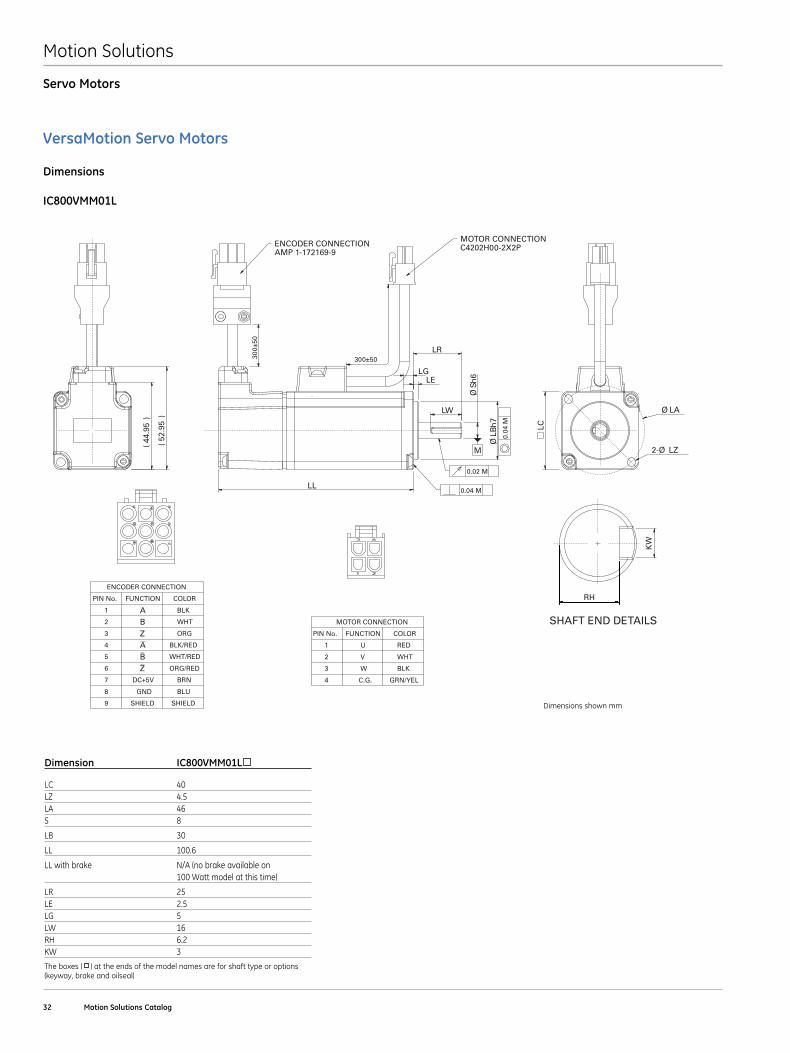
IC800VMM01L
0.0
4 M
Øh
7LB
LE
LR
300±
50
LL
Ø LA
2-Ø LZ
LC
()
44.9
5
()
52.9
5
LG
LW
RH
KW
M
Øh
6S
MOTOR CONNECTION
PIN No. FUNCTION COLOR
1 U RED
2 V WHT
3 W BLK
4 C.G. GRN/YEL
ENCODER CONNECTION
PIN No. FUNCTION COLOR
1 A BLK
2 B WHT
3 Z ORG
4 A BLK/RED
5 B WHT/RED
6 Z ORG/RED
7 DC+5V BRN
8 GND BLU
9 SHIELD SHIELD
SHAFT END DETAILS
300±50
0.04 M
ENCODER CONNECTIONAMP 1-172169-9
MOTOR CONNECTIONC4202H00-2X2P
0.02 M
Dimension IC800VMM01L
LC 40LZ 4 .5LA 46S 8
LB 30
LL 100 .6
LL with brake N/A (no brake available on 100 Watt model at this time)
LR 25LE 2 .5LG 5LW 16RH 6 .2KW 3
The boxes ( ) at the ends of the model names are for shaft type or options (keyway, brake and oilseal)
Dimensions shown mm
Motion Solutions
GE Intelligent Platforms | www .ge-ip .com 33
Servo Motors
VersaMotion Servo Motors
Dimensions
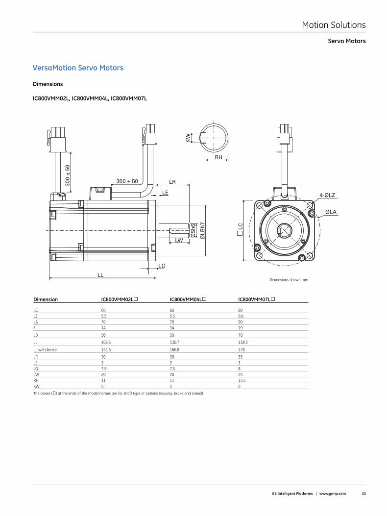
IC800VMM02L, IC800VMM04L, IC800VMM07L
300 ± 50 LR
RH
4-ØLZ
ØLA
LE
LW
LG
LL
ØS
h6
ØLB
h7
300
± 50
LC
KW
Dimension IC800VMM02L IC800VMM04L IC800VMM07L
LC 60 60 80LZ 5 .5 5 .5 6 .6LA 70 70 90S 14 14 19
LB 50 50 70
LL 105 .5 130 .7 138 .3
LL with brake 141 .6 166 .8 178
LR 30 30 35LE 3 3 3LG 7 .5 7 .5 8LW 20 20 25RH 11 11 15 .5KW 5 5 6
The boxes ( ) at the ends of the model names are for shaft type or options (keyway, brake and oilseal)
Dimensions shown mm
Motion Solutions
34 Motion Solutions Catalog
Servo Motors
VersaMotion Servo Motors
Dimensions
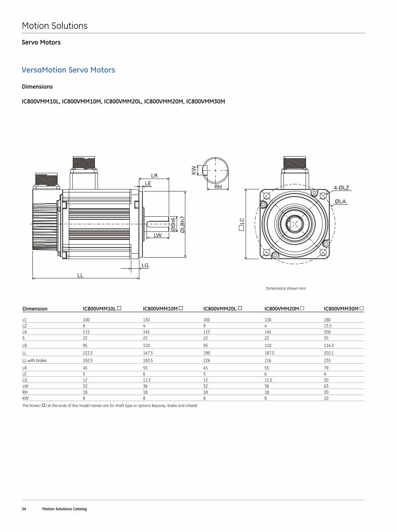
IC800VMM10L, IC800VMM10M, IC800VMM20L, IC800VMM20M, IC800VMM30M
LR
RH 4-ØLZ
ØLA
LE
LW
LG
LL
ØS
h6
ØLB
h7
LC
KW
Dimension IC800VMM10L IC800VMM10M IC800VMM20 L IC800VMM20 M IC800VMM30M
LC 100 130 100 130 180LZ 9 4 9 4 13 .5LA 115 145 115 145 200S 22 22 22 22 35
LB 95 110 95 110 114 .3
LL 153 .5 147 .5 199 187 .5 202 .1
LL with brake 192 .5 183 .5 226 216 235
LR 45 55 45 55 79LE 5 6 5 6 4LG 12 11 .5 12 11 .5 20LW 32 36 32 36 63RH 18 18 18 18 30KW 8 8 8 8 10
The boxes ( ) at the ends of the model names are for shaft type or options (keyway, brake and oilseal)
Dimensions shown mm
Motion Solutions
GE Intelligent Platforms | www .ge-ip .com 35
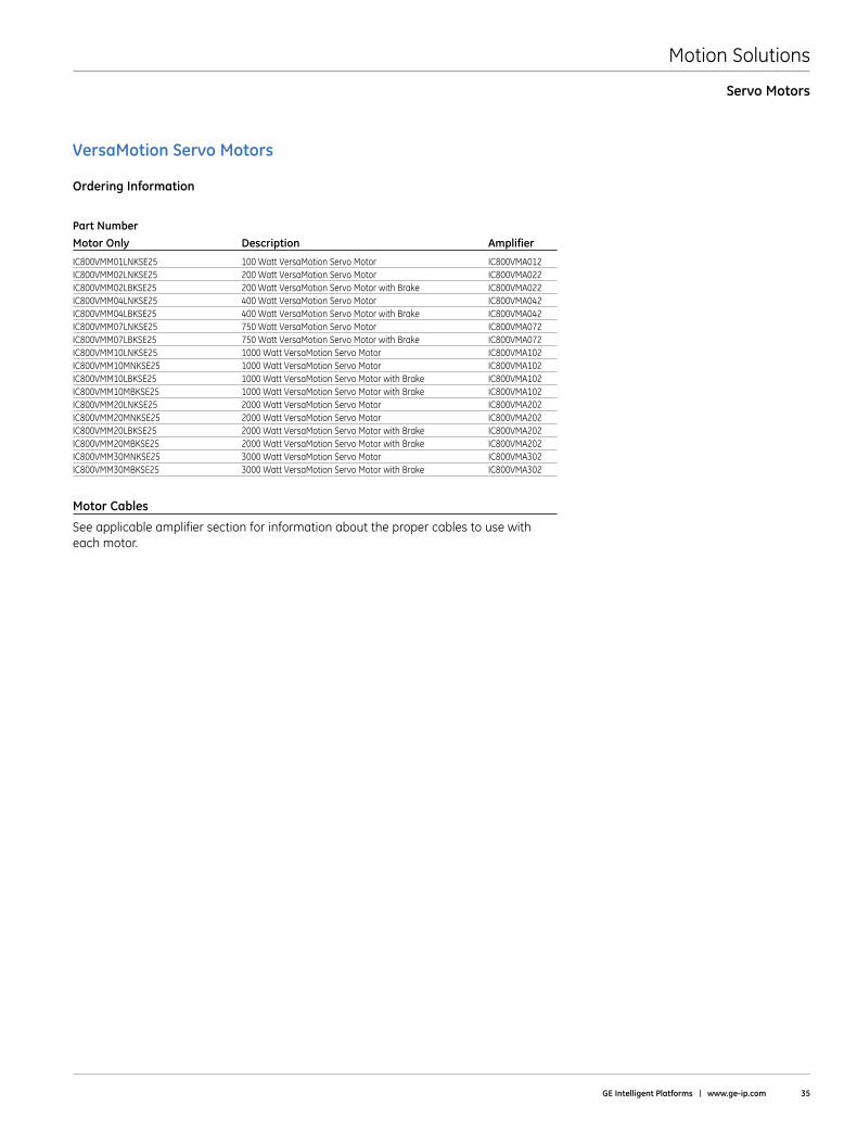
VersaMotion Servo Motors
Ordering Information
Part NumberMotor Only Description Amplifier
IC800VMM01LNKSE25 100 Watt VersaMotion Servo Motor IC800VMA012IC800VMM02LNKSE25 200 Watt VersaMotion Servo Motor IC800VMA022IC800VMM02LBKSE25 200 Watt VersaMotion Servo Motor with Brake IC800VMA022IC800VMM04LNKSE25 400 Watt VersaMotion Servo Motor IC800VMA042IC800VMM04LBKSE25 400 Watt VersaMotion Servo Motor with Brake IC800VMA042IC800VMM07LNKSE25 750 Watt VersaMotion Servo Motor IC800VMA072IC800VMM07LBKSE25 750 Watt VersaMotion Servo Motor with Brake IC800VMA072IC800VMM10LNKSE25 1000 Watt VersaMotion Servo Motor IC800VMA102IC800VMM10MNKSE25 1000 Watt VersaMotion Servo Motor IC800VMA102IC800VMM10LBKSE25 1000 Watt VersaMotion Servo Motor with Brake IC800VMA102IC800VMM10MBKSE25 1000 Watt VersaMotion Servo Motor with Brake IC800VMA102IC800VMM20LNKSE25 2000 Watt VersaMotion Servo Motor IC800VMA202IC800VMM20MNKSE25 2000 Watt VersaMotion Servo Motor IC800VMA202IC800VMM20LBKSE25 2000 Watt VersaMotion Servo Motor with Brake IC800VMA202IC800VMM20MBKSE25 2000 Watt VersaMotion Servo Motor with Brake IC800VMA202IC800VMM30MNKSE25 3000 Watt VersaMotion Servo Motor IC800VMA302IC800VMM30MBKSE25 3000 Watt VersaMotion Servo Motor with Brake IC800VMA302
Motor Cables
See applicable amplifier section for information about the proper cables to use with each motor .
Servo Motors
Motion Solutions
36 Motion Solutions Catalog
Servo Amplifiers
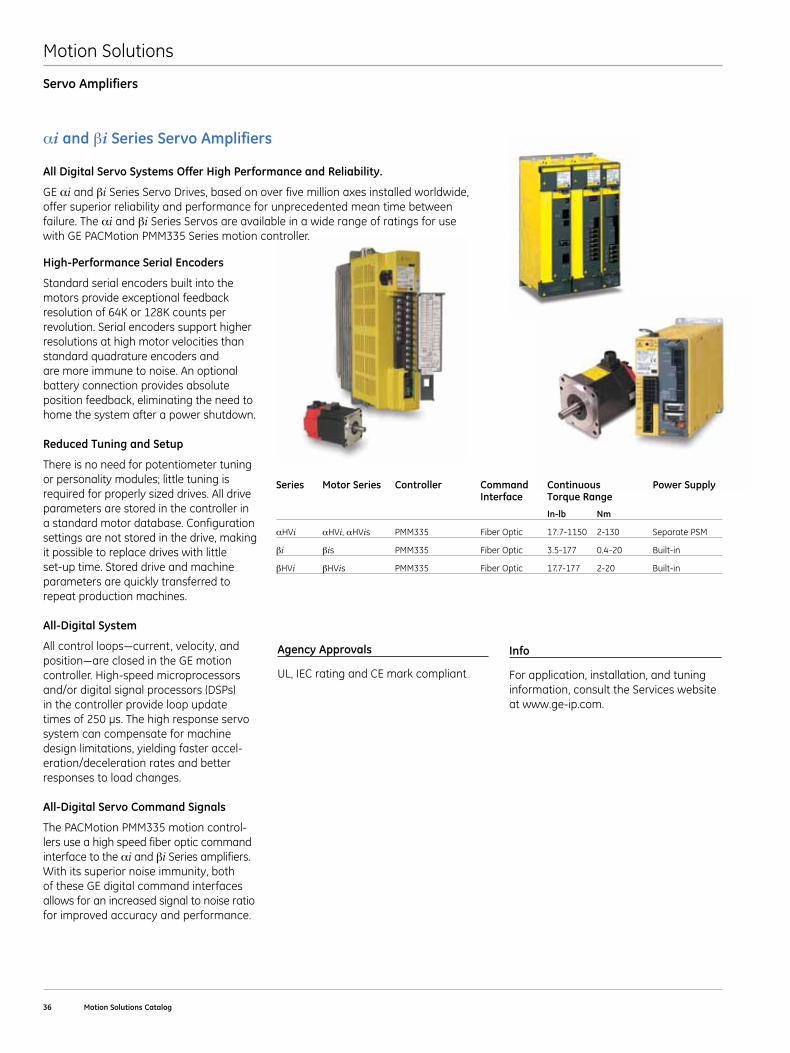
High-Performance Serial Encoders
Standard serial encoders built into the motors provide exceptional feedback resolution of 64K or 128K counts per revolution . Serial encoders support higher resolutions at high motor velocities than standard quadrature encoders and are more immune to noise . An optional battery connection provides absolute position feedback, eliminating the need to home the system after a power shutdown .
Reduced Tuning and Setup
There is no need for potentiometer tuning or personality modules; little tuning is required for properly sized drives . All drive parameters are stored in the controller in a standard motor database . Configuration settings are not stored in the drive, making it possible to replace drives with little set-up time . Stored drive and machine parameters are quickly transferred to repeat production machines .
All-Digital System
Allcontrolloops—current,velocity,andposition—areclosedintheGEmotioncontroller . High-speed microprocessors and/or digital signal processors (DSPs) in the controller provide loop update timesof250µs.Thehighresponseservosystem can compensate for machine design limitations, yielding faster accel-eration/deceleration rates and better responses to load changes .
All-Digital Servo Command Signals
The PACMotion PMM335 motion control-lers use a high speed fiber optic command interface to the αi and βi Series amplifiers . With its superior noise immunity, both of these GE digital command interfaces allows for an increased signal to noise ratio for improved accuracy and performance .
Info
For application, installation, and tuning information, consult the Services website at www .ge-ip .com .
Agency Approvals
UL, IEC rating and CE mark compliant
αi and βi Series Servo Amplifiers
All Digital Servo Systems Offer High Performance and Reliability .
GE αi and βi Series Servo Drives, based on over five million axes installed worldwide, offer superior reliability and performance for unprecedented mean time between failure . The αi and βi Series Servos are available in a wide range of ratings for use with GE PACMotion PMM335 Series motion controller .
Series Motor Series Controller Command Continuous Power Supply Interface Torque Range
In-lb Nm
αHVi αHVi, αHVis PMM335 Fiber Optic 17 .7-1150 2-130 Separate PSM
βi βis PMM335 Fiber Optic 3 .5-177 0 .4-20 Built-in
βHVi βHVis PMM335 Fiber Optic 17 .7-177 2-20 Built-in
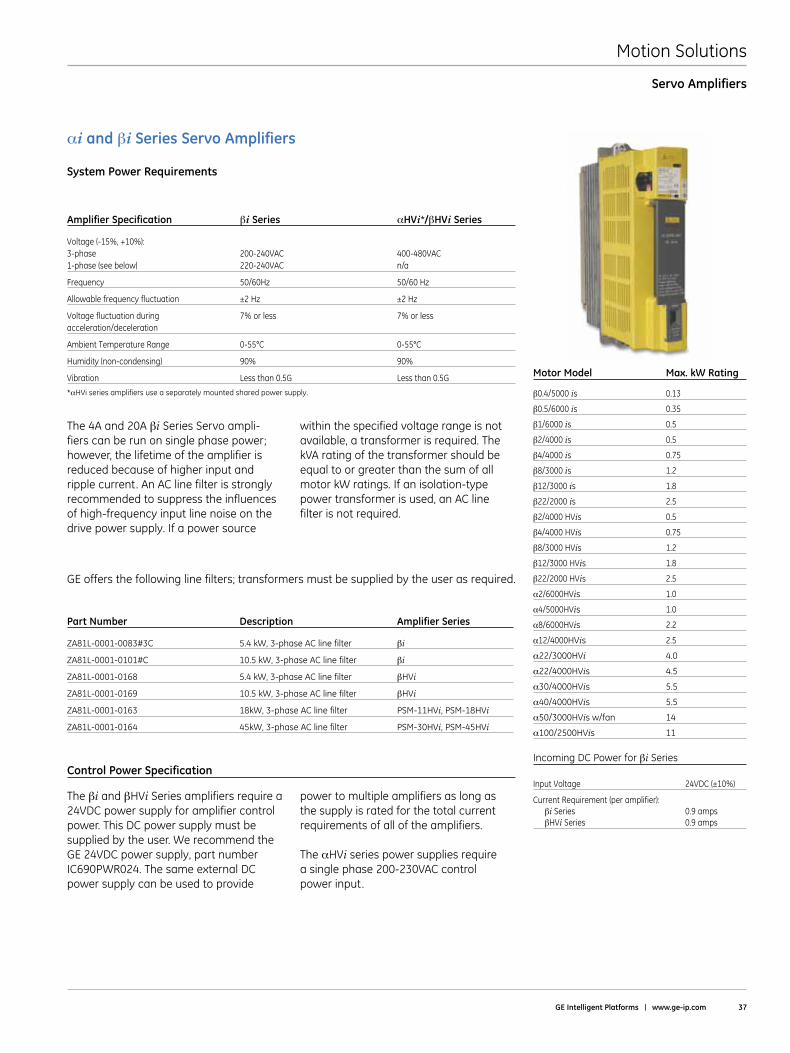
Motion Solutions
GE Intelligent Platforms | www .ge-ip .com 37
Servo Amplifiers
Part Number Description Amplifier Series
ZA81L-0001-0083#3C 5 .4 kW, 3-phase AC line filter βi
ZA81L-0001-0101#C 10 .5 kW, 3-phase AC line filter βi
ZA81L-0001-0168 5 .4 kW, 3-phase AC line filter βHVi
ZA81L-0001-0169 10 .5 kW, 3-phase AC line filter βHVi
ZA81L-0001-0163 18kW, 3-phase AC line filter PSM-11HVi, PSM-18HVi
ZA81L-0001-0164 45kW, 3-phase AC line filter PSM-30HVi, PSM-45HVi
The 4A and 20A βiSeries Servo ampli-fiers can be run on single phase power; however, the lifetime of the amplifier is reduced because of higher input and ripple current . An AC line filter is strongly recommended to suppress the influences of high-frequency input line noise on the drive power supply . If a power source
within the specified voltage range is not available, a transformer is required . The kVA rating of the transformer should be equal to or greater than the sum of all motor kW ratings . If an isolation-type power transformer is used, an AC line filter is not required .
GE offers the following line filters; transformers must be supplied by the user as required .
αi and βi Series Servo Amplifiers System Power Requirements
Amplifier Specification βiSeries αHVi*/βHViSeries
Voltage(-15%,+10%): 3-phase 200-240VAC 400-480VAC 1-phase (see below) 220-240VAC n/a
Frequency 50/60Hz 50/60 Hz
Allowable frequency fluctuation ±2 Hz ±2 Hz
Voltagefluctuationduring 7%orless 7%orless acceleration/deceleration
Ambient Temperature Range 0-55°C 0-55°C
Humidity(non-condensing) 90% 90%
Vibration Less than 0 .5G Less than 0 .5G Motor Model Max . kW Rating
β0 .4/5000 is 0 .13
β0 .5/6000 is 0 .35
β1/6000 is 0 .5
β2/4000 is 0 .5
β4/4000 is 0 .75
β8/3000 is 1 .2
β12/3000 is 1 .8
β22/2000 is 2 .5
β2/4000 HVis 0 .5
β4/4000 HVis 0 .75
β8/3000 HVis 1 .2
β12/3000 HVis 1 .8
β22/2000 HVis 2 .5
α2/6000HVis 1 .0
α4/5000HVis 1 .0
α8/6000HVis 2 .2
α12/4000HVis 2 .5
α22/3000HVi 4 .0
α22/4000HVis 4 .5
α30/4000HVis 5 .5
α40/4000HVis 5 .5
α50/3000HVis w/fan 14
α100/2500HVis 11
Incoming DC Power for βi Series
InputVoltage 24VDC(±10%)
Current Requirement (per amplifier): βi Series 0 .9 amps βHVi Series 0 .9 amps
Control Power Specification
The βi and βHVi Series amplifiers require a 24VDC power supply for amplifier control power . This DC power supply must be supplied by the user . We recommend the GE 24VDC power supply, part number IC690PWR024 . The same external DC power supply can be used to provide
power to multiple amplifiers as long as the supply is rated for the total current requirements of all of the amplifiers .
The αHVi series power supplies require a single phase 200-230VAC control power input .
*αHVi series amplifiers use a separately mounted shared power supply .
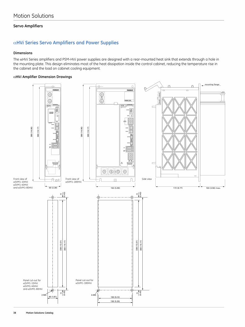
Motion Solutions
38 Motion Solutions Catalog
αHVi Series Servo Amplifiers and Power Supplies
Dimensions
αHVi Amplifier Dimension Drawings
Front view of αSVM1-180HVi
Front view of αSVM1-10HVi αSVM1-40HVi and αSVM1-80HVi
Panel cut-out for αSVM1-10HVi αSVM1-40HVi and αSVM1-80HVi
The αHVi Series amplifiers and PSM-HVi power supplies are designed with a rear-mounted heat sink that extends through a hole in the mounting plate . This design eliminates most of the heat dissipation inside the control cabinet, reducing the temperature rise in the cabinet and the load on cabinet cooling equipment .
Servo Amplifiers
FANUC
ENCODERBATTERY
CXA2B
CX5X
STATUS
BATTERY
CXA2A
COP10B
COP10A
JX5
ENC1JF1
CAUTIONHIGHVOLTAGEDISCHARGE TIME >2 min
380
(14.
96)
360
(14.
17)
172 (6.77)60 (2.36) 100 (3.94) max.
mounting flange
FANUC
CXA2B
AC200-240 V50/60 Hz
CX5X
CX1A CX1B
STATUS
CXA2A
COP10B
COP10A
JX5
ENC1JF1
CX8DBI
CX9DBC
CAUTIONWhen the LED is lit don’t touch the terminals.DISCHARGETIME
380
(14.
96)
360
(14.
17)
172 (6.77)150 (5.90) 100 (3.94) max.
mounting flange
>2 Mins
U V W
FANUC LTDYamenashi 401-0597 JAPAN
FANUC
CXA2B
AC200-240 V50/60 Hz
CX5X
CX1A CX1B
STATUS
CXA2A
COP10B
COP10A
JX5
ENC1JF1
CX8DBI
CX9DBC
CAUTIONWhen the LED is lit don’t touch the terminals.DISCHARGETIME
380
(14.
96)
360
(14.
17)
172 (6.77)150 (5.90) 100 (3.94) max.
mounting flange
>2 Mins
U V W
FANUC LTDYamenashi 401-0597 JAPAN
Side view
338
(13.
31)
1111 11 11
11 11
46 (1.81) 76 (2.99) 130 (5.12)
136 (5.35)
360
(14.
17)
(0.4
3)
(0.4
3)
(0.4
3)
338
(13.
31)
360
(14.
17)
338
(13.
31)
360
(14.
17)
2-M5 2-M5 4-M5(0.4
3)
(0.4
3)
(0.4
3)
338
(13.
31)
1111 11 11
11 11
46 (1.81) 76 (2.99) 130 (5.12)
136 (5.35)
360
(14.
17)
(0.4
3)
(0.4
3)
(0.4
3)
338
(13.
31)
360
(14.
17)
338
(13.
31)
360
(14.
17)
2-M5 2-M5 4-M5(0.4
3)
(0.4
3)
(0.4
3)
Panel cut-out for αSVM1-180HVi
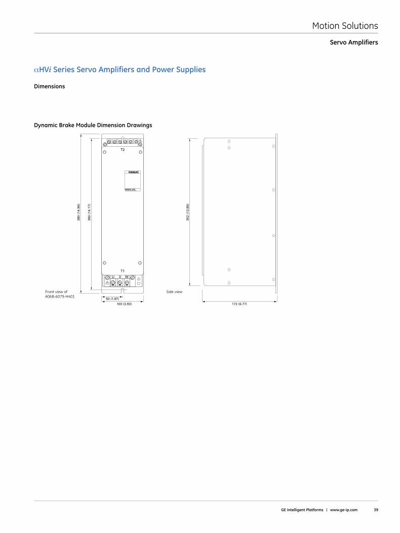
Motion Solutions
GE Intelligent Platforms | www .ge-ip .com 39
Dynamic Brake Module Dimension Drawings
αHVi Series Servo Amplifiers and Power Supplies
Dimensions
Servo Amplifiers
Front view of A06B-6079-H401
Side view
380
(14.
96)
360
(14.
17)
352
(13.
86)
100 (3.93)
50 (1.97)
172 (6.77)
U V
T1
T2
W
FANUC
Dynamic Brake Module (DBM)
FANUC LTDYamenashi 401-0597 JAPAN
380
(14.
96)
360
(14.
17)
352
(13.
86)
100 (3.93)
50 (1.97)
172 (6.77)
U V
T1
T2
W
FANUC
Dynamic Brake Module (DBM)
FANUC LTDYamenashi 401-0597 JAPAN
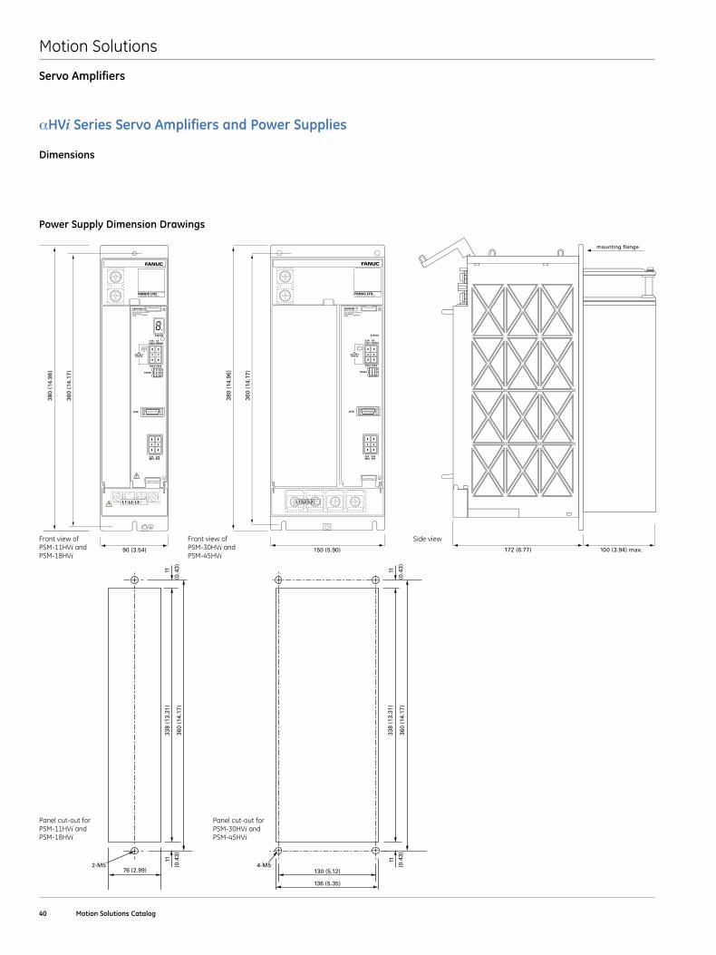
Motion Solutions
40 Motion Solutions Catalog
FANUC LTDYamenashi 401-0597 JAPAN
FANUC
CXA2A
AC200-240 V50/60 Hz
CX1A CX1B
STATUS
JX1B
CX3MCC
CX4ESP
CAUTIONWhen the LED is lit don’t touch the terminals.DISCHARGETIME
172 (6.77) 100 (3.94) max.
mounting flange
>2 Mins
L1 L2 L3
3.5AInput
1AOutput
380
(14.
96)
360
(14.
17)
90 (3.54)
Power Supply Dimension Drawings
αHVi Series Servo Amplifiers and Power Supplies
Dimensions
Servo Amplifiers
Front view of PSM-11HVi and PSM-18HVi
Front view of PSM-30HVi and PSM-45HVi
Side view
FANUC
380
(14.
96)
360
(14.
17)
172 (6.77)150 (5.90) 100 (3.94) max.
mounting flange
CXA2A
AC200-240 V50/60 Hz
CX1A CX1B
STATUS
JX1B
CX3MCC
CX4ESP
CAUTIONWhen the LED is lit don’t touch the terminals.DISCHARGETIME >2 Mins
L1 L2 L3
3.5AInput
1AOutput
FANUC LTDYamenashi 401-0597 JAPAN
FANUC
380
(14.
96)
360
(14.
17)
172 (6.77)150 (5.90) 100 (3.94) max.
mounting flange
CXA2A
AC200-240 V50/60 Hz
CX1A CX1B
STATUS
JX1B
CX3MCC
CX4ESP
CAUTIONWhen the LED is lit don’t touch the terminals.DISCHARGETIME >2 Mins
L1 L2 L3
3.5AInput
1AOutput
FANUC LTDYamenashi 401-0597 JAPAN
338
(13.
31)
1111 11 11
11 11
46 (1.81) 76 (2.99) 130 (5.12)
136 (5.35)
360
(14.
17)
(0.4
3)
(0.4
3)
(0.4
3)
338
(13.
31)
360
(14.
17)
338
(13.
31)
360
(14.
17)
2-M5 2-M5 4-M5(0.4
3)
(0.4
3)
(0.4
3)
338
(13.
31)
1111 11 11
11 11
46 (1.81) 76 (2.99) 130 (5.12)
136 (5.35)
360
(14.
17)
(0.4
3)
(0.4
3)
(0.4
3)
338
(13.
31)
360
(14.
17)
338
(13.
31)
360
(14.
17)
2-M5 2-M5 4-M5(0.4
3)
(0.4
3)
(0.4
3)
Panel cut-out for PSM-11HVi and PSM-18HVi
Panel cut-out for PSM-30HVi and PSM-45HVi
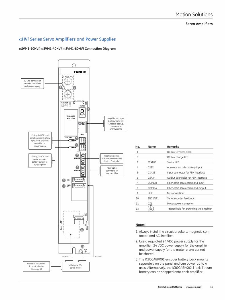
Motion Solutions
GE Intelligent Platforms | www .ge-ip .com 41
αHVi Series Servo Amplifiers and Power Supplies
αSVM1-10HVi, αSVM1-40HVi, αSVM1-80HVi Connection Diagram
Servo Amplifiers
No . Name Remarks
1 DC link terminal block
2 DC link charge LED
3 STATUS Status LED
4 CX5X Absolute encoder battery input
5 CXA2B Input connector for PSM interface
6 CXA2A Output connector for PSM interface
7 COP10B Fiber optic servo command input
8 COP10A Fiber optic servo command output
9 JX5 No connection
10 ENC1/JF1 Serial encoder feedback
11 CZ2 Motor power connector
12 Tapped hole for grounding the amplifier
FANUC
ENCODERBATTERY
CXA2B
CX5X
STATUS
BATTERY
CXA2A
COP10B
COP10A
JX5
ENC1JF1
CAUTIONHIGHVOLTAGEDISCHARGE TIME >2 min
1
3
4
5
6
7
8
9
10
11
12
2
DC Link connectionbetween amplifiersand power supply
Fiber optic cableto PACMotion PMM335
Motion Controller
Fiber opticcommand tonext amplifier
Amplifier mounted battery for Serial Encoder Backup.
(See note 3)IC800ABK002
E-stop, 24VDC andserial encoder batteryinput from previous
amplifier or power supply
E-stop, 24VDC andserial encoder
battery output to next amplifier
Optional 24V powerfor motor brake
(See note 2)
power encoder
αHVi or αHVisseries motor
Notes:
1 . Always install the circuit breakers, magnetic con-tactor, and AC line filter .
2 . Use a regulated 24 VDC power supply for the amplifier . 24 VDC power supply for the amplifier and power supply for the motor brake cannot be shared .
3 . The IC800ABK001 encoder battery pack mounts separately on the panel and can power up to 4 axes . Alternatively, the IC800ABK002 1-axis lithium battery can be snapped onto each amplifier .
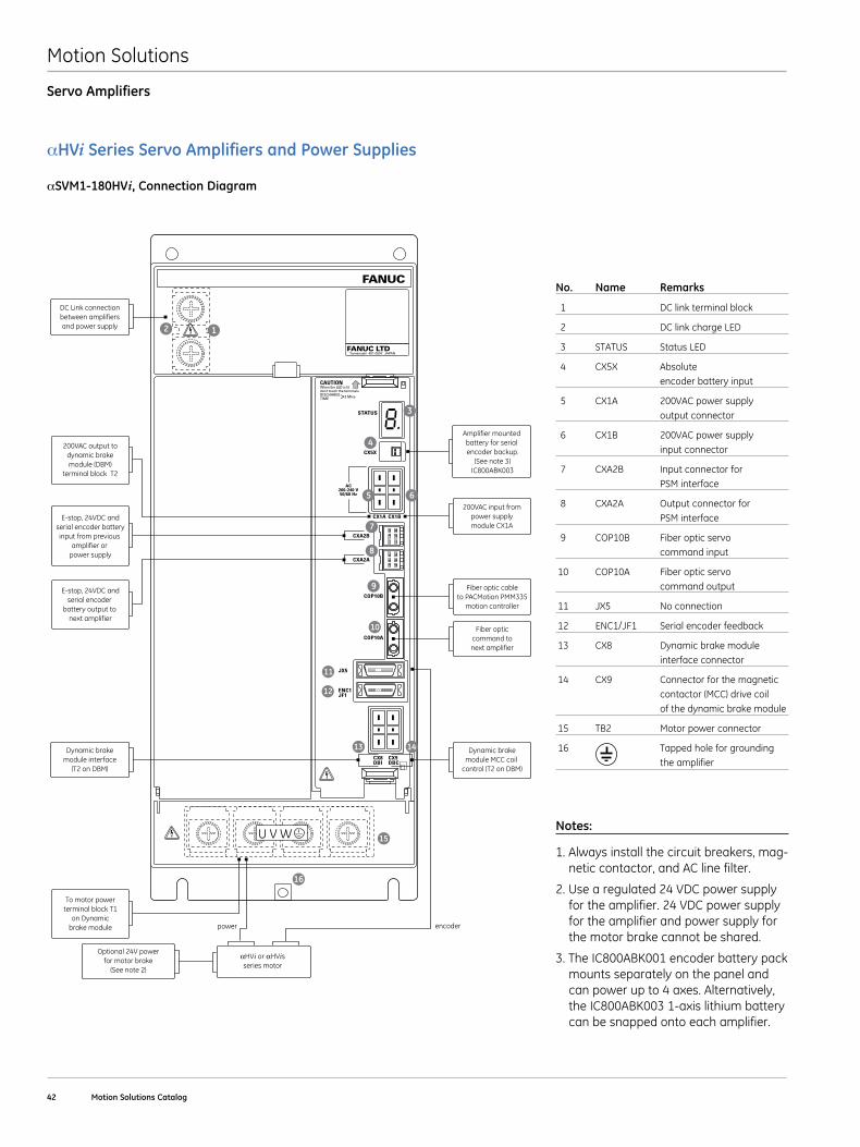
Motion Solutions
42 Motion Solutions Catalog
αHVi Series Servo Amplifiers and Power Supplies
αSVM1-180HVi, Connection Diagram
Servo Amplifiers
FANUC
CXA2B
AC200-240 V50/60 Hz
CX5X
CX1A CX1B
STATUS
CXA2A
COP10B
COP10A
JX5
ENC1JF1
CX8DBI
CX9DBC
CAUTIONWhen the LED is lit don’t touch the terminals.DISCHARGETIME >2 Mins
U V W
FANUC LTDYamenashi 401-0597 JAPAN
4
5 6
7
8
9
10
11
12
15
1413
16
12
3
DC Link connectionbetween amplifiersand power supply
Dynamic brakemodule interface
(T2 on DBM)
Amplifier mounted battery for serial encoder backup.
(See note 3)IC800ABK003
Fiber optic cableto PACMotion PMM335
motion controller
200VAC input frompower supplymodule CX1A
Dynamic brakemodule MCC coil
control (T2 on DBM)
Fiber opticcommand tonext amplifier
E-stop, 24VDC andserial encoder batteryinput from previous
amplifier or power supply
E-stop, 24VDC andserial encoder
battery output to next amplifier
200VAC output todynamic brakemodule (DBM)
terminal block T2
Optional 24V powerfor motor brake
(See note 2)
power encoder
αHVi or αHVisseries motor
To motor powerterminal block T1
on Dynamicbrake module
Dynamic brakemodule MCC coil
control (T2 on DBM)
No . Name Remarks
1 DC link terminal block
2 DC link charge LED
3 STATUS Status LED
4 CX5X Absolute encoder battery input
5 CX1A 200VAC power supply output connector
6 CX1B 200VAC power supply input connector
7 CXA2B Input connector for PSM interface
8 CXA2A Output connector for PSM interface
9 COP10B Fiber optic servo command input
10 COP10A Fiber optic servo command output
11 JX5 No connection
12 ENC1/JF1 Serial encoder feedback
13 CX8 Dynamic brake module interface connector
14 CX9 Connector for the magnetic contactor (MCC) drive coil of the dynamic brake module
15 TB2 Motor power connector
16 Tapped hole for grounding the amplifier
Notes:
1 . Always install the circuit breakers, mag-netic contactor, and AC line filter .
2 . Use a regulated 24 VDC power supply for the amplifier . 24 VDC power supply for the amplifier and power supply for the motor brake cannot be shared .
3 . The IC800ABK001 encoder battery pack mounts separately on the panel and can power up to 4 axes . Alternatively, the IC800ABK003 1-axis lithium battery can be snapped onto each amplifier .
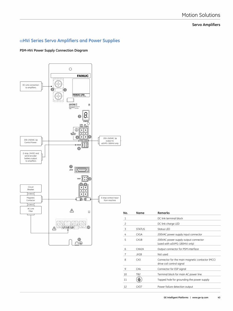
Motion Solutions
GE Intelligent Platforms | www .ge-ip .com 43
αHVi Series Servo Amplifiers and Power Supplies
PSM-HVi Power Supply Connection Diagram
Servo Amplifiers
No . Name Remarks
1 DC link terminal block
2 DC link charge LED
3 STATUS Status LED
4 CX1A 200VAC power supply input connector
5 CX1B 200VAC power supply output connector (used with αSVM1-180HVi only)
6 CXA2A Output connector for PSM interface
7 JX1B Not used
8 CX3 Connector for the main magnetic contactor (MCC) drive coil control signal
9 CX4 Connector for ESP signal
10 TB2 Terminal block for main AC power line
11 Tapped hole for grounding the power supply
12 CX37 Power failure detection output
FANUC LTDYamenashi 401-0597 JAPAN
FANUC
CXA2A
AC200-240 V50/60 Hz
CX1A CX1B
STATUS
JX1B
CX37
CX3MCC
CX4ESP
CAUTIONWhen the LED is lit don’t touch the terminals.DISCHARGETIME >2 Mins
L1 L2 L3
4 5
6
7
11
10
9
12
8
12
3
3.5AInput
1AOutput
DC Link connectionto amplifiers
MagneticContactor
E-stop contact inputfrom machine
CircuitBreaker
AC LineFilter
200–240VAC 1φoutput to
αSVM1-180HVi only
E-stop, 24VDC andserial encoder battery output
to amplifiers
200–240VAC 1φControl Power
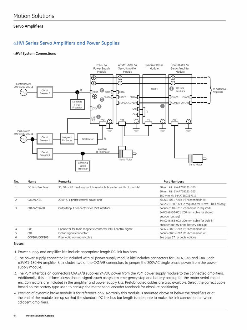
Motion Solutions
44 Motion Solutions Catalog
αHVi Series Servo Amplifiers and Power Supplies
αHVi System Connections
Notes:
1 . Power supply and amplifier kits include appropriate length DC link bus bars .
2 . The power supply connector kit included with all power supply module kits includes connectors for CX1A, CX3 and CX4 . Each αSVM1-180HVi amplifier kit includes two of the CX1A/B connectors to jumper the 200VAC single phase power from the power supply module .
3 . The PSM interface on connectors CXA2A/B supplies 24VDC power from the PSM power supply module to the connected amplifiers . Additionally, this interface allows shared signals such as system emergency stop and battery backup for the motor serial encod-ers . Connectors are included in the amplifier and power supply kits . Prefabricated cables are also available . Select the correct cable based on the battery type used to backup the motor serial encoder feedback for absolute positioning .
4 . Position of dynamic brake module is for reference only . Normally this module is mounted above or below the amplifiers or at the end of the module line up so that the standard DC link bus bar length is adequate to make the link connection between adjacent amplifiers .
No . Name Remarks Part Numbers
1 DC Link Bus Bars 30, 60 or 90 mm long bar kits available based on width of module1 60 mm kit: Z44A718031-G05 90 mm kit: Z44A718031-G03 150 mm kit: Z44A718031-G12 2 CX1A/CX1B 200VAC 1 phase control power unit2 ZA06B-6071-K203 (PSM connector kit) ZA02B-0120-K321 (2 required for αSVM1-180HVi only) 3 CXA2A/CXA2B Output/input connectors for PSM interface3 ZA06B-6110-K210 (connector: 2 required) Z44C746453-001 (200 mm cable for shared encoder battery) Z44C746453-002 (200 mm cable for built-in encoder battery or no battery backup) 4 CX3 Connector for main magnetic contactor (MCC) control signal2 ZA06B-6071-K203 (PSM connector kit) 5 CX4 E-Stop signal connector2 ZA06B-6071-K203 (PSM connector kit) 6 COP10A/COP10B Fiber optic command cable See page 17 for cable options
PSM-HViPower Supply
Module
αSVM1-180HViServo Amplifier
Module
Dynamic BrakeModule
αSVM1-80HViServo Amplifier
Module
CircuitBreaker 2
CircuitBreaker 1
Main Power400 to 480 VAC 3φ
Control Power200 to 240 VAC 1φ
MagneticContactor AC Reactor
Servo Motor
CX1A
CX4
TB2 TB2 T1 CZ2CX3MCC
CX1B CX1A
DC LinkBus Bars
CXA2A CXA2B
COP10A
CXA2A CXA2B
To AdditionalAmplifiers
CXA2A
Servo Motor
α50HVis3φ Fan MotorCircuit
Breaker 3
LightningSurge
Protector
LightningSurge
Protector
file name: aHViSystemconnection.epsfile name: aHViSystemconnection.eps
3φ
1φ
COP10B COP10B
CX8T2
CX9
COP10A
Servo Amplifiers
(Note 4)
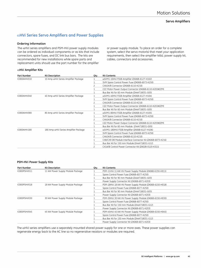
Motion Solutions
GE Intelligent Platforms | www .ge-ip .com 45
Servo Amplifiers
The αHVi series amplifiers and PSM-HVi power supply modules can be ordered as individual components or as kits that include connectors, spare fuses, and DC link bus bars . The kits are recommended for new installations while spare parts and replacement units should use the part number for the amplifier
or power supply module . To place an order for a complete system, select the servo motor(s) that meet your application requirements, then select the amplifier kit(s), power supply kit, cables, connectors and accessories .
αHVi Amplifier Kits
αHVi Series Servo Amplifiers and Power Supplies
Ordering Information
Part Number Kit Description Qty . Kit ContentsIC800AIHV010 10 Amp αHVi Series Amplifier Package 1 αSVM1-10HVi FSSB Amplifier (ZA06B-6127-H102) 1 SVM Spare Control Power Fuse (ZA06B-6073-K250) 2 CXA2A/B Connector (ZA06B-6110-K210) 1 CZ2 Motor Power Output Connector (ZA06B-6110-K203#ZZM) 1 Bus Bar Kit for 60 mm Module (Z44A718031-G05)IC800AIHV040 40 Amp αHVi Series Amplifier Package 1 αSVM1-40HVi FSSB Amplifier (ZA06B-6127-H104) 1 SVM Spare Control Power Fuse (ZA06B-6073-K250) 2 CXA2A/B Connector (ZA06B-6110-K210) 1 CZ2 Motor Power Output Connector (ZA06B-6110-K203#ZZM) 1 Bus Bar Kit for 60 mm Module (Z44A718031-G05)IC800AIHV080 80 Amp αHVi Series Amplifier Package 1 αSVM1-80HVi FSSB Amplifier (ZA06B-6127-H105) 1 SVM Spare Control Power Fuse (ZA06B-6073-K250) 2 CXA2A/B Connector (ZA06B-6110-K210) 1 CZ2 Motor Power Output Connector (ZA06B-6110-K203#ZZM) 1 Bus Bar Kit for 60 mm Module (Z44A718031-G05) IC800AIHV180 180 Amp αHVi Series Amplifier Package 1 αSVM1-180HVi FSSB Amplifier (ZA06B-6127-H106) 1 SVM Spare Control Power Fuse (ZA06B-6073-K250) 2 CXA2A/B Connector (ZA06B-6110-K210) 1 CX8/CX9 DB Module Interface Connector Kit (ZA06B-6073-K216) 1 Bus Bar Kit for 150 mm Module (Z44A718031-G12) 2 CX1A/B Control Power Connector Kit (ZA02B-0120-K321)
PSM-HVi Power Supply Kits
Part Number Kit Description Qty . Kit ContentsIC800PSHV011 11 kW Power Supply Module Package 1 PSM-11HVi 11 kW HV Power Supply Module (ZA06B-6150-H011) 1 Spare Control Power Fuse (ZA06B-6077-K250) 1 Bus Bar Kit for 90 mm Module (Z44A718031-G03) 1 Power Supply Connector Kit (ZA06B-6071-K203) IC800PSHV018 18 kW Power Supply Module Package 1 PSM-18HVi 18 kW HV Power Supply Module (ZA06B-6150-H018) 1 Spare Control Power Fuse (ZA06B-6077-K250) 1 Bus Bar Kit for 90 mm Module (Z44A718031-G03) 1 Power Supply Connector Kit (ZA06B-6071-K203) IC800PSHV030 30 kW Power Supply Module Package 1 PSM-30HVi 30 kW HV Power Supply Module (ZA06B-6150-H030) 1 Spare Control Power Fuse (ZA06B-6077-K250) 1 Bus Bar Kit for 150 mm Module (Z44A718031-G12) 1 Power Supply Connector Kit (ZA06B-6071-K203) IC800PSHV045 45 kW Power Supply Module Package 1 PSM-45HVi 45 kW HV Power Supply Module (ZA06B-6150-H045) 1 Spare Control Power Fuse (ZA06B-6077-K250) 1 Bus Bar Kit for 150 mm Module (Z44A718031-G12) 1 Power Supply Connector Kit (ZA06B-6071-K203)
The αHVi series amplifiers use a separately mounted shared power supply for one or more axes . These power supplies can regenerate energy back to the AC line so no regenerative resistors or modules are required .
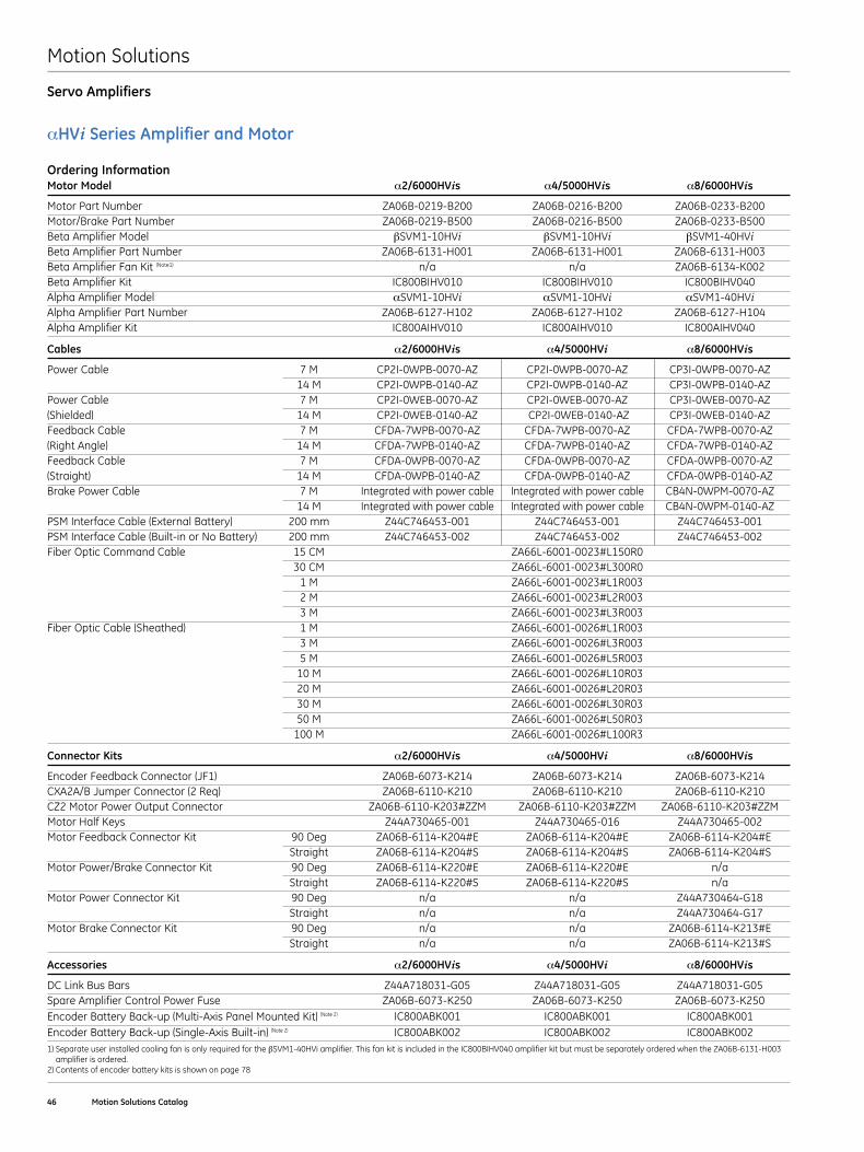
Motion Solutions
46 Motion Solutions Catalog
Servo Amplifiers
αHVi Series Amplifier and Motor
Ordering InformationMotor Model α2/6000HVis α4/5000HVis α8/6000HVis
Motor Part Number ZA06B-0219-B200 ZA06B-0216-B200 ZA06B-0233-B200Motor/Brake Part Number ZA06B-0219-B500 ZA06B-0216-B500 ZA06B-0233-B500Beta Amplifier Model βSVM1-10HVi βSVM1-10HVi βSVM1-40HViBeta Amplifier Part Number ZA06B-6131-H001 ZA06B-6131-H001 ZA06B-6131-H003Beta Amplifier Fan Kit (Note1) n/a n/a ZA06B-6134-K002Beta Amplifier Kit IC800BIHV010 IC800BIHV010 IC800BIHV040Alpha Amplifier Model αSVM1-10HVi αSVM1-10HVi αSVM1-40HViAlpha Amplifier Part Number ZA06B-6127-H102 ZA06B-6127-H102 ZA06B-6127-H104Alpha Amplifier Kit IC800AIHV010 IC800AIHV010 IC800AIHV040
Cables α2/6000HVis α4/5000HVi α8/6000HVis
Power Cable 7 M CP2I-0WPB-0070-AZ CP2I-0WPB-0070-AZ CP3I-0WPB-0070-AZ 14 M CP2I-0WPB-0140-AZ CP2I-0WPB-0140-AZ CP3I-0WPB-0140-AZPower Cable 7 M CP2I-0WEB-0070-AZ CP2I-0WEB-0070-AZ CP3I-0WEB-0070-AZ(Shielded) 14 M CP2I-0WEB-0140-AZ CP2I-0WEB-0140-AZ CP3I-0WEB-0140-AZFeedback Cable 7 M CFDA-7WPB-0070-AZ CFDA-7WPB-0070-AZ CFDA-7WPB-0070-AZ(Right Angle) 14 M CFDA-7WPB-0140-AZ CFDA-7WPB-0140-AZ CFDA-7WPB-0140-AZFeedback Cable 7 M CFDA-0WPB-0070-AZ CFDA-0WPB-0070-AZ CFDA-0WPB-0070-AZ(Straight) 14 M CFDA-0WPB-0140-AZ CFDA-0WPB-0140-AZ CFDA-0WPB-0140-AZBrake Power Cable 7 M Integrated with power cable Integrated with power cable CB4N-0WPM-0070-AZ 14 M Integrated with power cable Integrated with power cable CB4N-0WPM-0140-AZPSM Interface Cable (External Battery) 200 mm Z44C746453-001 Z44C746453-001 Z44C746453-001PSM Interface Cable (Built-in or No Battery) 200 mm Z44C746453-002 Z44C746453-002 Z44C746453-002Fiber Optic Command Cable 15 CM ZA66L-6001-0023#L150R0 30 CM ZA66L-6001-0023#L300R0 1 M ZA66L-6001-0023#L1R003 2 M ZA66L-6001-0023#L2R003 3 M ZA66L-6001-0023#L3R003Fiber Optic Cable (Sheathed) 1 M ZA66L-6001-0026#L1R003 3 M ZA66L-6001-0026#L3R003 5 M ZA66L-6001-0026#L5R003 10 M ZA66L-6001-0026#L10R03 20 M ZA66L-6001-0026#L20R03 30 M ZA66L-6001-0026#L30R03 50 M ZA66L-6001-0026#L50R03 100 M ZA66L-6001-0026#L100R3
Connector Kits α2/6000HVis α4/5000HVi α8/6000HVis
Encoder Feedback Connector (JF1) ZA06B-6073-K214 ZA06B-6073-K214 ZA06B-6073-K214CXA2A/B Jumper Connector (2 Req) ZA06B-6110-K210 ZA06B-6110-K210 ZA06B-6110-K210CZ2 Motor Power Output Connector ZA06B-6110-K203#ZZM ZA06B-6110-K203#ZZM ZA06B-6110-K203#ZZMMotor Half Keys Z44A730465-001 Z44A730465-016 Z44A730465-002Motor Feedback Connector Kit 90 Deg ZA06B-6114-K204#E ZA06B-6114-K204#E ZA06B-6114-K204#E Straight ZA06B-6114-K204#S ZA06B-6114-K204#S ZA06B-6114-K204#SMotor Power/Brake Connector Kit 90 Deg ZA06B-6114-K220#E ZA06B-6114-K220#E n/a Straight ZA06B-6114-K220#S ZA06B-6114-K220#S n/aMotor Power Connector Kit 90 Deg n/a n/a Z44A730464-G18 Straight n/a n/a Z44A730464-G17Motor Brake Connector Kit 90 Deg n/a n/a ZA06B-6114-K213#E Straight n/a n/a ZA06B-6114-K213#S
Accessories α2/6000HVis α4/5000HVi α8/6000HVis
DC Link Bus Bars Z44A718031-G05 Z44A718031-G05 Z44A718031-G05Spare Amplifier Control Power Fuse ZA06B-6073-K250 ZA06B-6073-K250 ZA06B-6073-K250Encoder Battery Back-up (Multi-Axis Panel Mounted Kit) (Note 2) IC800ABK001 IC800ABK001 IC800ABK001Encoder Battery Back-up (Single-Axis Built-in) (Note 2) IC800ABK002 IC800ABK002 IC800ABK0021) Separate user installed cooling fan is only required for the βSVM1-40HVi amplifier . This fan kit is included in the IC800BIHV040 amplifier kit but must be separately ordered when the ZA06B-6131-H003
amplifier is ordered .2) Contents of encoder battery kits is shown on page 78
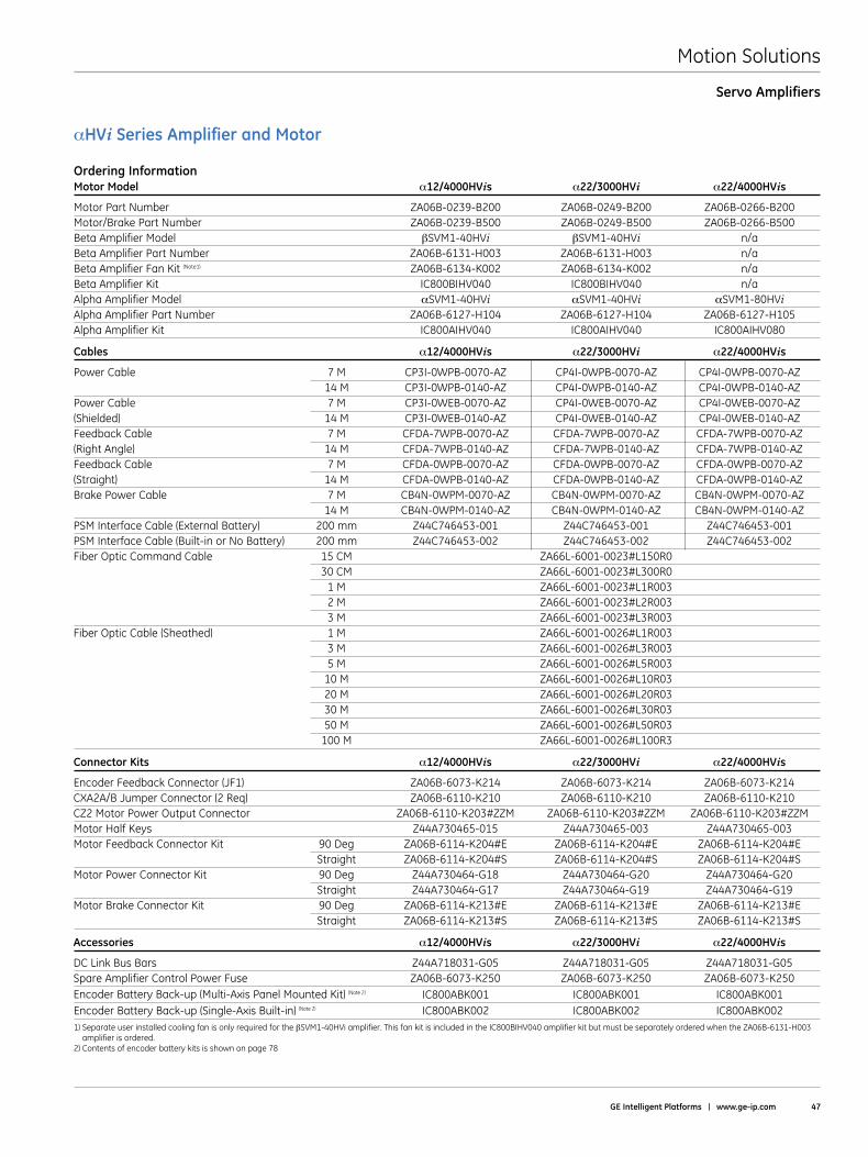
Motion Solutions
GE Intelligent Platforms | www .ge-ip .com 47
Servo Amplifiers
αHVi Series Amplifier and Motor
Ordering InformationMotor Model α12/4000HVis α22/3000HVi α22/4000HVis
Motor Part Number ZA06B-0239-B200 ZA06B-0249-B200 ZA06B-0266-B200Motor/Brake Part Number ZA06B-0239-B500 ZA06B-0249-B500 ZA06B-0266-B500Beta Amplifier Model βSVM1-40HVi βSVM1-40HVi n/aBeta Amplifier Part Number ZA06B-6131-H003 ZA06B-6131-H003 n/aBeta Amplifier Fan Kit (Note1) ZA06B-6134-K002 ZA06B-6134-K002 n/aBeta Amplifier Kit IC800BIHV040 IC800BIHV040 n/aAlpha Amplifier Model αSVM1-40HVi αSVM1-40HVi αSVM1-80HViAlpha Amplifier Part Number ZA06B-6127-H104 ZA06B-6127-H104 ZA06B-6127-H105Alpha Amplifier Kit IC800AIHV040 IC800AIHV040 IC800AIHV080
Cables α12/4000HVis α22/3000HVi α22/4000HVis
Power Cable 7 M CP3I-0WPB-0070-AZ CP4I-0WPB-0070-AZ CP4I-0WPB-0070-AZ 14 M CP3I-0WPB-0140-AZ CP4I-0WPB-0140-AZ CP4I-0WPB-0140-AZPower Cable 7 M CP3I-0WEB-0070-AZ CP4I-0WEB-0070-AZ CP4I-0WEB-0070-AZ(Shielded) 14 M CP3I-0WEB-0140-AZ CP4I-0WEB-0140-AZ CP4I-0WEB-0140-AZFeedback Cable 7 M CFDA-7WPB-0070-AZ CFDA-7WPB-0070-AZ CFDA-7WPB-0070-AZ(Right Angle) 14 M CFDA-7WPB-0140-AZ CFDA-7WPB-0140-AZ CFDA-7WPB-0140-AZFeedback Cable 7 M CFDA-0WPB-0070-AZ CFDA-0WPB-0070-AZ CFDA-0WPB-0070-AZ(Straight) 14 M CFDA-0WPB-0140-AZ CFDA-0WPB-0140-AZ CFDA-0WPB-0140-AZBrake Power Cable 7 M CB4N-0WPM-0070-AZ CB4N-0WPM-0070-AZ CB4N-0WPM-0070-AZ 14 M CB4N-0WPM-0140-AZ CB4N-0WPM-0140-AZ CB4N-0WPM-0140-AZPSM Interface Cable (External Battery) 200 mm Z44C746453-001 Z44C746453-001 Z44C746453-001PSM Interface Cable (Built-in or No Battery) 200 mm Z44C746453-002 Z44C746453-002 Z44C746453-002Fiber Optic Command Cable 15 CM ZA66L-6001-0023#L150R0 30 CM ZA66L-6001-0023#L300R0 1 M ZA66L-6001-0023#L1R003 2 M ZA66L-6001-0023#L2R003 3 M ZA66L-6001-0023#L3R003Fiber Optic Cable (Sheathed) 1 M ZA66L-6001-0026#L1R003 3 M ZA66L-6001-0026#L3R003 5 M ZA66L-6001-0026#L5R003 10 M ZA66L-6001-0026#L10R03 20 M ZA66L-6001-0026#L20R03 30 M ZA66L-6001-0026#L30R03 50 M ZA66L-6001-0026#L50R03 100 M ZA66L-6001-0026#L100R3
Connector Kits α12/4000HVis α22/3000HVi α22/4000HVis
Encoder Feedback Connector (JF1) ZA06B-6073-K214 ZA06B-6073-K214 ZA06B-6073-K214CXA2A/B Jumper Connector (2 Req) ZA06B-6110-K210 ZA06B-6110-K210 ZA06B-6110-K210CZ2 Motor Power Output Connector ZA06B-6110-K203#ZZM ZA06B-6110-K203#ZZM ZA06B-6110-K203#ZZMMotor Half Keys Z44A730465-015 Z44A730465-003 Z44A730465-003Motor Feedback Connector Kit 90 Deg ZA06B-6114-K204#E ZA06B-6114-K204#E ZA06B-6114-K204#E Straight ZA06B-6114-K204#S ZA06B-6114-K204#S ZA06B-6114-K204#SMotor Power Connector Kit 90 Deg Z44A730464-G18 Z44A730464-G20 Z44A730464-G20 Straight Z44A730464-G17 Z44A730464-G19 Z44A730464-G19Motor Brake Connector Kit 90 Deg ZA06B-6114-K213#E ZA06B-6114-K213#E ZA06B-6114-K213#E Straight ZA06B-6114-K213#S ZA06B-6114-K213#S ZA06B-6114-K213#S
Accessories α12/4000HVis α22/3000HVi α22/4000HVis
DC Link Bus Bars Z44A718031-G05 Z44A718031-G05 Z44A718031-G05Spare Amplifier Control Power Fuse ZA06B-6073-K250 ZA06B-6073-K250 ZA06B-6073-K250Encoder Battery Back-up (Multi-Axis Panel Mounted Kit) (Note 2) IC800ABK001 IC800ABK001 IC800ABK001Encoder Battery Back-up (Single-Axis Built-in) (Note 2) IC800ABK002 IC800ABK002 IC800ABK0021) Separate user installed cooling fan is only required for the βSVM1-40HVi amplifier . This fan kit is included in the IC800BIHV040 amplifier kit but must be separately ordered when the ZA06B-6131-H003
amplifier is ordered .2) Contents of encoder battery kits is shown on page 78
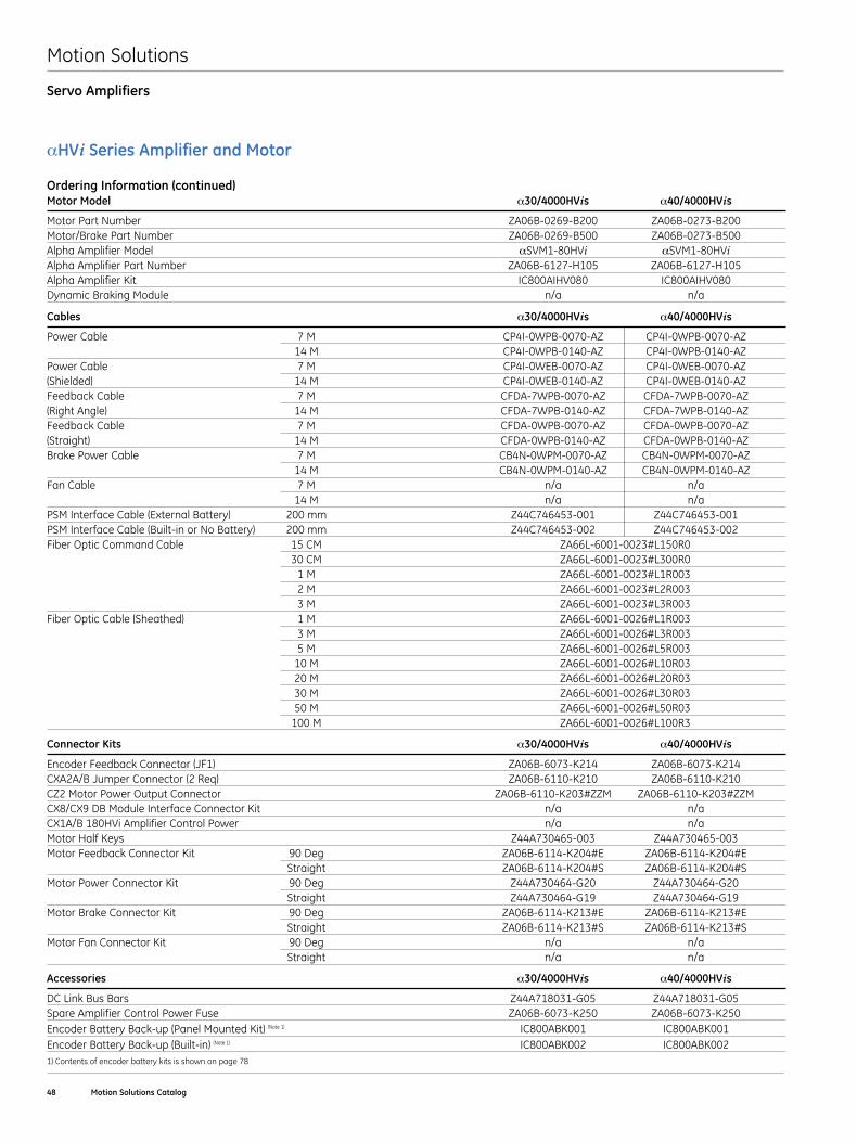
Motion Solutions
48 Motion Solutions Catalog
αHVi Series Amplifier and Motor
Ordering Information (continued)Motor Model α30/4000HVis α40/4000HVis
Motor Part Number ZA06B-0269-B200 ZA06B-0273-B200Motor/Brake Part Number ZA06B-0269-B500 ZA06B-0273-B500Alpha Amplifier Model αSVM1-80HVi αSVM1-80HViAlpha Amplifier Part Number ZA06B-6127-H105 ZA06B-6127-H105Alpha Amplifier Kit IC800AIHV080 IC800AIHV080Dynamic Braking Module n/a n/a
Cables α30/4000HVis α40/4000HVis
Power Cable 7 M CP4I-0WPB-0070-AZ CP4I-0WPB-0070-AZ 14 M CP4I-0WPB-0140-AZ CP4I-0WPB-0140-AZPower Cable 7 M CP4I-0WEB-0070-AZ CP4I-0WEB-0070-AZ(Shielded) 14 M CP4I-0WEB-0140-AZ CP4I-0WEB-0140-AZFeedback Cable 7 M CFDA-7WPB-0070-AZ CFDA-7WPB-0070-AZ(Right Angle) 14 M CFDA-7WPB-0140-AZ CFDA-7WPB-0140-AZFeedback Cable 7 M CFDA-0WPB-0070-AZ CFDA-0WPB-0070-AZ(Straight) 14 M CFDA-0WPB-0140-AZ CFDA-0WPB-0140-AZBrake Power Cable 7 M CB4N-0WPM-0070-AZ CB4N-0WPM-0070-AZ 14 M CB4N-0WPM-0140-AZ CB4N-0WPM-0140-AZFan Cable 7 M n/a n/a 14 M n/a n/aPSM Interface Cable (External Battery) 200 mm Z44C746453-001 Z44C746453-001PSM Interface Cable (Built-in or No Battery) 200 mm Z44C746453-002 Z44C746453-002Fiber Optic Command Cable 15 CM ZA66L-6001-0023#L150R0 30 CM ZA66L-6001-0023#L300R0 1 M ZA66L-6001-0023#L1R003 2 M ZA66L-6001-0023#L2R003 3 M ZA66L-6001-0023#L3R003Fiber Optic Cable (Sheathed) 1 M ZA66L-6001-0026#L1R003 3 M ZA66L-6001-0026#L3R003 5 M ZA66L-6001-0026#L5R003 10 M ZA66L-6001-0026#L10R03 20 M ZA66L-6001-0026#L20R03 30 M ZA66L-6001-0026#L30R03 50 M ZA66L-6001-0026#L50R03 100 M ZA66L-6001-0026#L100R3
Connector Kits α30/4000HVis α40/4000HVis
Encoder Feedback Connector (JF1) ZA06B-6073-K214 ZA06B-6073-K214CXA2A/B Jumper Connector (2 Req) ZA06B-6110-K210 ZA06B-6110-K210CZ2 Motor Power Output Connector ZA06B-6110-K203#ZZM ZA06B-6110-K203#ZZMCX8/CX9 DB Module Interface Connector Kit n/a n/aCX1A/B 180HVi Amplifier Control Power n/a n/aMotor Half Keys Z44A730465-003 Z44A730465-003Motor Feedback Connector Kit 90 Deg ZA06B-6114-K204#E ZA06B-6114-K204#E Straight ZA06B-6114-K204#S ZA06B-6114-K204#SMotor Power Connector Kit 90 Deg Z44A730464-G20 Z44A730464-G20 Straight Z44A730464-G19 Z44A730464-G19Motor Brake Connector Kit 90 Deg ZA06B-6114-K213#E ZA06B-6114-K213#E Straight ZA06B-6114-K213#S ZA06B-6114-K213#SMotor Fan Connector Kit 90 Deg n/a n/a Straight n/a n/a
Accessories α30/4000HVis α40/4000HVis
DC Link Bus Bars Z44A718031-G05 Z44A718031-G05Spare Amplifier Control Power Fuse ZA06B-6073-K250 ZA06B-6073-K250Encoder Battery Back-up (Panel Mounted Kit) (Note 1) IC800ABK001 IC800ABK001Encoder Battery Back-up (Built-in) (Note 1) IC800ABK002 IC800ABK0021) Contents of encoder battery kits is shown on page 78
Servo Amplifiers
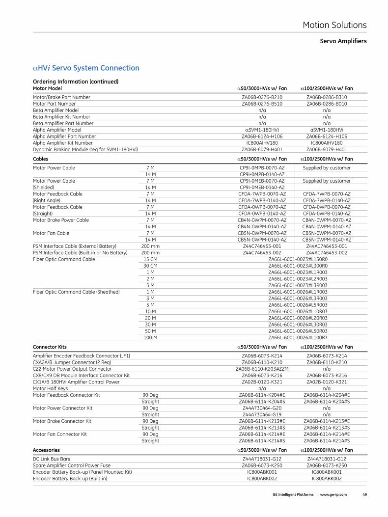
Motion Solutions
GE Intelligent Platforms | www .ge-ip .com 49
αHVi Servo System Connection
Ordering Information (continued)Motor Model α50/3000HVis w/ Fan α100/2500HVis w/ Fan
Motor/Brake Part Number ZA06B-0276-B210 ZA06B-0286-B310Motor Part Number ZA06B-0276-B510 ZA06B-0286-B010Beta Amplifier Model n/a n/aBeta Amplifier Kit Number n/a n/aBeta Amplifier Part Number n/a n/aAlpha Amplifier Model αSVM1-180HVi aSVM1-180HViAlpha Amplifier Part Number ZA06B-6124-H106 ZA06B-6124-H106Alpha Amplifier Kit Number IC800AIHV180 IC800AIHV180Dynamic Braking Module (req for SVM1-180HVi) ZA06B-6079-H401 ZA06B-6079-H401
Cables α50/3000HVis w/ Fan α100/2500HVis w/ Fan
Motor Power Cable 7 M CP9I-0MPB-0070-AZ Supplied by customer 14 M CP9I-0MPB-0140-AZMotor Power Cable 7 M CP9I-0MEB-0070-AZ Supplied by customer(Shielded) 14 M CP9I-0MEB-0140-AZ Motor Feedback Cable 7 M CFDA-7WPB-0070-AZ CFDA-7WPB-0070-AZ(Right Angle) 14 M CFDA-7WPB-0140-AZ CFDA-7WPB-0140-AZMotor Feedback Cable 7 M CFDA-0WPB-0070-AZ CFDA-0WPB-0070-AZ(Straight) 14 M CFDA-0WPB-0140-AZ CFDA-0WPB-0140-AZMotor Brake Power Cable 7 M CB4N-0WPM-0070-AZ CB4N-0WPM-0070-AZ 14 M CB4N-0WPM-0140-AZ CB4N-0WPM-0140-AZMotor Fan Cable 7 M CB5N-0WPM-0070-AZ CB5N-0WPM-0070-AZ 14 M CB5N-0WPM-0140-AZ CB5N-0WPM-0140-AZPSM Interface Cable (External Battery) 200 mm Z44C746453-001 Z44AC746453-001PSM Interface Cable (Built-in or No Battery) 200 mm Z44C746453-002 Z44AC746453-002Fiber Optic Command Cable 15 CM ZA66L-6001-0023#L150R0 30 CM ZA66L-6001-0023#L300R0 1 M ZA66L-6001-0023#L1R003 2 M ZA66L-6001-0023#L2R003 3 M ZA66L-6001-0023#L3R003Fiber Optic Command Cable (Sheathed) 1 M ZA66L-6001-0026#L1R003 3 M ZA66L-6001-0026#L3R003 5 M ZA66L-6001-0026#L5R003 10 M ZA66L-6001-0026#L10R03 20 M ZA66L-6001-0026#L20R03 30 M ZA66L-6001-0026#L30R03 50 M ZA66L-6001-0026#L50R03 100 M ZA66L-6001-0026#L100R3
Connector Kits α50/3000HVis w/ Fan α100/2500HVis w/ Fan
Amplifier Encoder Feedback Connector (JF1) ZA06B-6073-K214 ZA06B-6073-K214CXA2A/B Jumper Connector (2 Req) ZA06B-6110-K210 ZA06B-6110-K210CZ2 Motor Power Output Connector ZA06B-6110-K203#ZZM n/aCX8/CX9 DB Module Interface Connector Kit ZA06B-6073-K216 ZA06B-6073-K216CX1A/B 180HVi Amplifier Control Power ZA02B-0120-K321 ZA02B-0120-K321Motor Half Keys n/a n/aMotor Feedback Connector Kit 90 Deg ZA06B-6114-K204#E ZA06B-6114-K204#E Straight ZA06B-6114-K204#S ZA06B-6114-K204#SMotor Power Connector Kit 90 Deg Z44A730464-G20 n/a Straight Z44A730464-G19 n/aMotor Brake Connector Kit 90 Deg ZA06B-6114-K213#E ZA06B-6114-K213#E Straight ZA06B-6114-K213#S ZA06B-6114-K213#SMotor Fan Connector Kit 90 Deg ZA06B-6114-K214#E ZA06B-6114-K214#E Straight ZA06B-6114-K214#S ZA06B-6114-K214#S
Accessories α50/3000HVis w/ Fan α100/2500HVis w/ Fan
DC Link Bus Bars Z44A718031-G12 Z44A718031-G12Spare Amplifier Control Power Fuse ZA06B-6073-K250 ZA06B-6073-K250Encoder Battery Back-up (Panel Mounted Kit) IC800ABK001 IC800ABK001Encoder Battery Back-up (Built-in) IC800ABK002 IC800ABK002
Servo Amplifiers
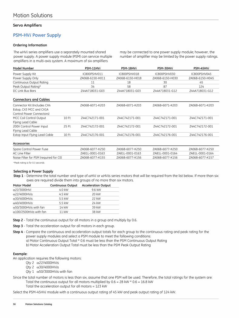
Motion Solutions
50 Motion Solutions Catalog
Servo Amplifiers
PSM-HVi Power Supply
Ordering Information
The αHVi series amplifiers use a separately mounted shared power supply . A power supply module (PSM) can service multiple amplifiers in a multi-axis system . A maximum of six amplifiers
may be connected to one power supply module; however, the number of amplifier may be limited by the power supply ratings .
Model Number PSM-11HVi PSM-18HVi PSM-30HVi PSM-45HVi
Power Supply Kit IC800PSHV011 IC800PSHV018 IC800PSHV030 IC800PSHV045Power Supply Only ZA06B-6150-H011 ZA06B-6150-H018 ZA06B-6150-H030 ZA06B-6150-H045Continuous Output Rating 11 18 30 45Peak Output Rating* 34 58 87 124DC Link Bus Bars Z44A718031-G03 Z44A718031-G03 Z44A718031-G12 Z44A718031-G12
Connectors and Cables
Connector Kit (Includes CX4 ZA06B-6071-K203 ZA06B-6071-K203 ZA06B-6071-K203 ZA06B-6071-K203 Estop, CX3 MCC and CX1A Control Power Connectors)MCC Coil Control Output 10 Ft Z44C742171-001 Z44C742171-001 Z44C742171-001 Z44C742171-001 Flying Lead Cable200V Control Power Input 25 Ft Z44C742172-001 Z44C742172-001 Z44C742172-001 Z44C742172-001 Flying Lead CableEstop Input Flying Lead Cable 10 Ft Z44C742176-001 Z44C742176-001 Z44C742176-001 Z44C742176-001
Accessories
Spare Control Power Fuse ZA06B-6077-K250 ZA06B-6077-K250 ZA06B-6077-K250 ZA06B-6077-K250AC Line Filter ZA81L-0001-0163 ZA81L-0001-0163 ZA81L-0001-0164 ZA81L-0001-0164Noise Filter for PSM (required for CE) ZA06B-6077-K155 ZA06B-6077-K156 ZA06B-6077-K156 ZA06B-6077-K157
*Peak rating is for 0 .3 seconds
Selecting a Power SupplyStep 1 - Determine the total number and type of αHVi or αHVis series motors that will be required from the list below . If more than six
axes are required divide them into groups of no more than six motors .Motor Model Continuous Output Acceleration Output α22/3000HVi 4 .0 kW 9 .6 kW α22/4000HVis 4 .5 kW 20 kW α30/4000HVis 5 .5 kW 22 kW α40/4000HVis 5 .5 kW 24 kW α50/3000HVis with fan 14 kW 39 kWα100/2500HVis with fan 11 kW 38 kW Step 2 - Total the continuous output for all motors in a group and multiply by 0 .6 .
Step 3 - Total the acceleration output for all motors in each group .
Step 4 - Compare the continuous and acceleration output totals for each group to the continuous rating and peak rating for the power supply modules and select a PSM module to meet the following conditions: a) Motor Continuous Output Total * 0 .6 must be less than the PSM Continuous Output Rating b) Motor Acceleration Output Total must be less than the PSM Peak Output Rating
Example: An application requires the following motors: Qty 2 α22/4000HVis Qty 2 α30/4000HVis Qty 1 α50/3000HVis with fan
Since the total number of motors is less than six, assume that one PSM will be used . Therefore, the total ratings for the system are: Total the continuous output for all motors multiplied by 0 .6 = 28 kW * 0 .6 = 16 .8 kW Total the acceleration output for all motors = 123 kW
Select the PSM-45HVi module with a continuous output rating of 45 kW and peak output rating of 124 kW .

Motion Solutions
GE Intelligent Platforms | www .ge-ip .com 51
Feature Comparison
Feature αHVis Series βis Series βHVis Series
Cont . Stall Torque Range (In-lb (Nm)) 17 .7-664 (2-75) 3 .5-177 (0 .4-20) 17 .7-177 (2-20)Cont . Speed Range (RPM) 2000-6000 2000-6000 2000-4000Max . Speed Range (RPM) 3000-6000 2000-6000 2000-4000Compatible Amplifiers αHVi Series βi Series βHVi SeriesCompatible Controllers PMM335/DSM324i PMM335/DSM324i PMM335/DSM324iMounting Metric Metric MetricShaft Configuration Straight/Keyway Straight/Keyway Straight/KeywayBrushless Construction Yes Yes YesOptional Brake 24VDC 24 VDC 24 VDCFeedback Type Serial Encoder Serial Encoder Serial EncoderFeedback Resolution (Counts/rev) 1 M 64 K/128 K 128 KAbsolute Feedback Yes* Yes* Yes*Amplifier Line Voltage 400-480 VAC 3 φ 220-240 VAC 1 φ 400-480 VAC 3 φ 200-240 VAC 3 φShaft Seal Standard Standard StandardProtection Rating IP65 Standard IP65 Standard IP65 Standard IP67 Optional IP67 Optional IP67 OptionalInertia Low Medium Medium
*Absolute feedback requires optional encoder battery backup for αHVi Series, βi Series, or βHVi Series amplifiers .
Servo Motor Performance for Demanding ApplicationsThe FANUC Servo motors are a rugged family of brushless servo motors covering a broad torque and speed range . These motors utilize high energy rare earth magnets for superior cost/perfor-mance ratio . Low inertia design provides high acceleration rates for improved machine cycle rates . The αi and βi Series motors use high resolution serial encoder feedback and are matched with amplifiers and PACMotion PMM335 Motion Controllers .
αi and βi Series Servo Motors
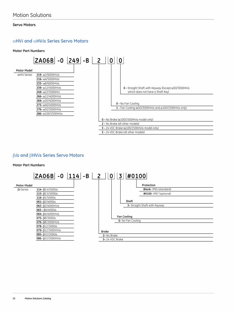
Motion Solutions
52 Motion Solutions Catalog
Servo Motors
αHVi and αHVis Series Servo Motors
Motor Part Numbers
0 - Straight Shaft with Keyway (Except α50/3000HVis which does not have a Shaft Key)
0 - No Brake (α100/2500HVis model only)2 - No Brake (all other models)3 - 24 VDC Brake (α100/2500HVis model only) 5 - 24 VDC Brake (all other models)
ZA06B 249-0 -B 2 0 0
0 - No Fan Cooling1 - Fan Cooling (α50/3000HVis and α100/2500HVis only)
Motor Model αHVi Series 219- α2/6000HVis 216- α4/5000HVis 233- α8/6000HVis 239- α12/4000HVis 249- α22/3000HVi 266- α22/4000HVis 269- α30/4000HVis 273- α40/4000HVis 276- α50/3000HVis 286- α100/2500HVis
βis and βHVis Series Servo Motors
Motor Part Numbers
Shaft3- Straight Shaft with Keyway
Brake 2- No Brake 5- 24 VDC Brake
ZA06B 114-0 -B 2 0 3
Fan Cooling 0- No Fan Cooling
Motor Model βi Series 114- β0.4/5000is 115- β0.5/5000is 116- β1/5000is 061- β2/4000is 062- β2/4000HVis 063 - β4/4000is 064- β4/4000HVis 075- β8/3000is 076- β8/3000HVis 078- β12/3000is 079- β12/3000HVis 085- β22/2000is 086- β22/2000HVis
#0100Protection Blank- IP65 (standard)
#0100- IP67 (optional)
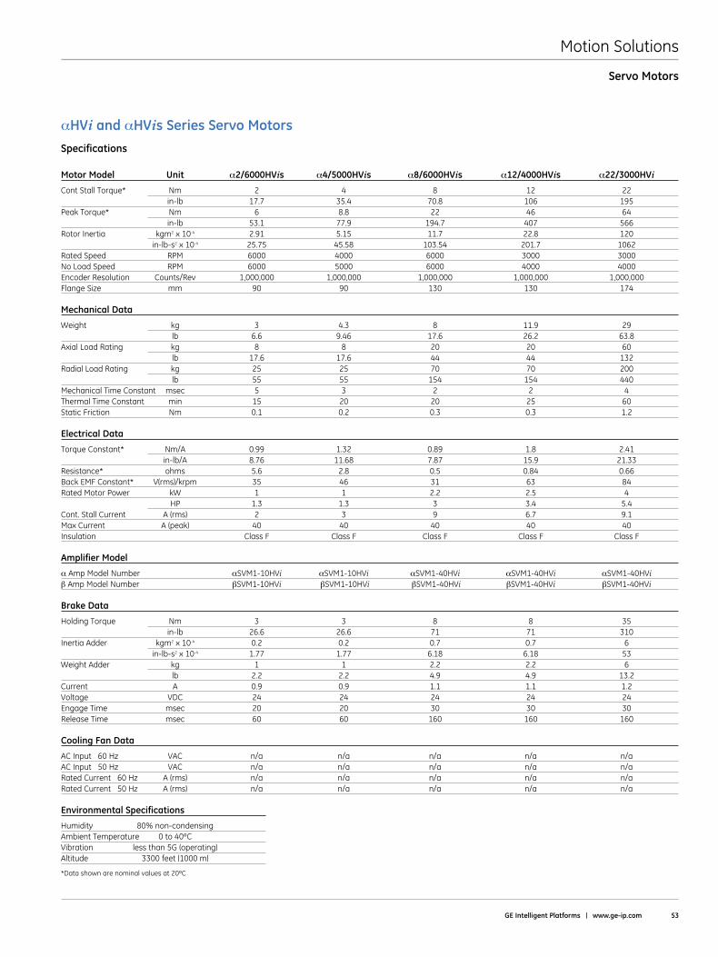
Motion Solutions
GE Intelligent Platforms | www .ge-ip .com 53
Servo Motors
αHVi and αHVis Series Servo MotorsSpecifications
Motor Model Unit α2/6000HVis α4/5000HVis α8/6000HVis α12/4000HVis α22/3000HVi
Cont Stall Torque* Nm 2 4 8 12 22 in-lb 17 .7 35 .4 70 .8 106 195Peak Torque* Nm 6 8 .8 22 46 64 in-lb 53 .1 77 .9 194 .7 407 566Rotor Inertia kgm2 x 10-4 2 .91 5 .15 11 .7 22 .8 120 in-lb-s2 x 10-4 25 .75 45 .58 103 .54 201 .7 1062Rated Speed RPM 6000 4000 6000 3000 3000No Load Speed RPM 6000 5000 6000 4000 4000Encoder Resolution Counts/Rev 1,000,000 1,000,000 1,000,000 1,000,000 1,000,000Flange Size mm 90 90 130 130 174
Mechanical Data
Weight kg 3 4 .3 8 11 .9 29 lb 6 .6 9 .46 17 .6 26 .2 63 .8Axial Load Rating kg 8 8 20 20 60 lb 17 .6 17 .6 44 44 132Radial Load Rating kg 25 25 70 70 200 lb 55 55 154 154 440Mechanical Time Constant msec 5 3 2 2 4Thermal Time Constant min 15 20 20 25 60Static Friction Nm 0 .1 0 .2 0 .3 0 .3 1 .2
Electrical Data
Torque Constant* Nm/A 0 .99 1 .32 0 .89 1 .8 2 .41 in-lb/A 8 .76 11 .68 7 .87 15 .9 21 .33Resistance* ohms 5 .6 2 .8 0 .5 0 .84 0 .66Back EMF Constant* V(rms)/krpm 35 46 31 63 84Rated Motor Power kW 1 1 2 .2 2 .5 4 HP 1 .3 1 .3 3 3 .4 5 .4Cont . Stall Current A (rms) 2 3 9 6 .7 9 .1Max Current A (peak) 40 40 40 40 40Insulation Class F Class F Class F Class F Class F
Amplifier Model
α Amp Model Number αSVM1-10HVi αSVM1-10HVi αSVM1-40HVi αSVM1-40HVi αSVM1-40HViβ Amp Model Number βSVM1-10HVi βSVM1-10HVi βSVM1-40HVi βSVM1-40HVi βSVM1-40HVi
Brake Data
Holding Torque Nm 3 3 8 8 35 in-lb 26 .6 26 .6 71 71 310Inertia Adder kgm2 x 10-4 0 .2 0 .2 0 .7 0 .7 6 in-lb-s2 x 10-4 1 .77 1 .77 6 .18 6 .18 53Weight Adder kg 1 1 2 .2 2 .2 6 lb 2 .2 2 .2 4 .9 4 .9 13 .2Current A 0 .9 0 .9 1 .1 1 .1 1 .2Voltage VDC 24 24 24 24 24Engage Time msec 20 20 30 30 30Release Time msec 60 60 160 160 160
Cooling Fan Data
AC Input 60 Hz VAC n/a n/a n/a n/a n/aAC Input 50 Hz VAC n/a n/a n/a n/a n/aRated Current 60 Hz A (rms) n/a n/a n/a n/a n/aRated Current 50 Hz A (rms) n/a n/a n/a n/a n/a
Environmental Specifications
Humidity 80%non-condensingAmbient Temperature 0 to 40ºCVibration less than 5G (operating)Altitude 3300 feet (1000 m)
*Data shown are nominal values at 20ºC
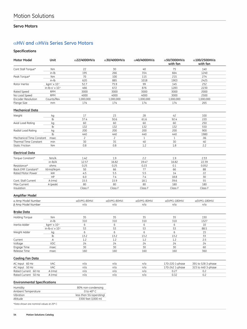
Motion Solutions
54 Motion Solutions Catalog
Servo Motors
αHVi and αHVis Series Servo MotorsSpecifications
Motor Model Unit α22/4000HVis α30/4000HVis α40/4000HVis α50/3000HVis α100/2500HVis with fan with fan
Cont Stall Torque* Nm 22 30 40 75 140 in-lb 195 266 354 664 1240Peak Torque* Nm 70 100 115 215 274 in-lb 620 885 1018 1903 2425Rotor Inertia kgm2 x 10-4 52 .7 75 .9 99 145 252 in-lb-s2 x 10-4 466 672 876 1283 2230Rated Speed RPM 3000 3000 3000 3000 2000No Load Speed RPM 4000 4000 4000 3000 2500Encoder Resolution Counts/Rev 1,000,000 1,000,000 1,000,000 1,000,000 1,000,000Flange Size mm 174 174 174 174 265
Mechanical Data
Weight kg 17 23 28 42 100 lb 37 .4 50 .6 61 .6 92 .4 220Axial Load Rating kg 60 60 60 60 250 lb 132 132 132 132 550Radial Load Rating kg 200 200 200 200 900 lb 440 440 440 440 1980Mechanical Time Constant msec 2 2 1 1 .06Thermal Time Constant min 30 35 40 30 40Static Friction Nm 0 .8 0 .8 1 .2 1 .8 2 .2
Electrical Data
Torque Constant* Nm/A 1 .42 1 .9 2 .2 1 .9 2 .53 in-lb/A 12 .57 16 .82 19 .47 16 .82 22 .39Resistance* ohms 0 .25 0 .25 0 .23 0 .1 0 .052Back EMF Constant* V(rms)/krpm 50 66 77 66 88Rated Motor Power kW 4 .5 5 .5 5 .5 14 22 HP 6 .0 7 .4 7 .4 18 .8 30Cont . Stall Current A (rms) 15 .5 15 .9 18 .1 39 .6 55Max Current A (peak) 80 80 80 180 180Insulation Class F Class F Class F Class F Class F
Amplifier Model
α Amp Model Number αSVM1-80HVi αSVM1-80HVi αSVM1-80HVi αSVM1-180HVi αSVM1-180HViβ Amp Model Number n/a n/a n/a n/a n/a
Brake Data
Holding Torque Nm 35 35 35 35 150 in-lb 310 310 310 310 1327Inertia Adder kgm2 x 10-4 6 6 6 6 10 in-lb-s2 x 10-4 53 53 53 53 88 .5Weight Adder kg 6 6 6 6 15 lb 13 .2 13 .2 13 .2 13 .2 33Current A 1 .2 1 .2 1 .2 1 .2 2 .5Voltage VDC 24 24 24 24 24Engage Time msec 30 30 30 30 60Release Time msec 160 160 160 160 360
Cooling Fan Data
AC Input 60 Hz VAC n/a n/a n/a 170-220 1-phase 391 to 528 3-phaseAC Input 50 Hz VAC n/a n/a n/a 170-242 1-phase 323 to 440 3-phaseRated Current 60 Hz A (rms) n/a n/a n/a 0 .27 0 .2Rated Current 50 Hz A (rms) n/a n/a n/a 0 .32 0 .2
Environmental Specifications
Humidity 80%non-condensing Ambient Temperature 0 to 40º C Vibration less than 5G (operating) Altitude 3300 feet (1000 m)
*Data shown are nominal values at 20º C
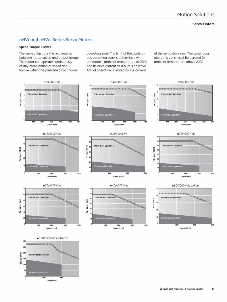
Motion Solutions
GE Intelligent Platforms | www .ge-ip .com 55
Servo Motors
αHVi and αHVis Series Servo MotorsSpeed Torque Curves
The curves illustrate the relationship between motor speed and output torque . The motor can operate continuously at any combination of speed and torque within the prescribed continuous
operating zone . The limit of the continu-ous operating zone is determined with the motor’s ambient temperature at 20°C and its drive current as a pure sine wave . Actual operation is limited by the current
of the servo drive unit . The continuous operating zone must be derated for ambient temperature above 20°C .
10000
30
40
50
20
10
60
70
2000 3000
Torq
ue
(Nm
)
α22/3000HVi
Speed (RPM)
Intermittent Operation
Continuous Operation
Torq
ue
(Nm
)
α12/4000HVis
Speed (RPM)
0
10
20
40
50
30
300020001000 4000
Intermittent Operation
Continuous Operation
Torq
ue
(Nm
)
α22/4000HVis
Speed (RPM)
0
10
20
40
50
30
60
70
80
300020001000 4000
Intermittent Operation
Continuous Operation
α4/5000HVis
Torq
ue
(Nm
)
Speed (RPM)40002000 500030001000
Intermittent Operation
Continuous Operation
0
3
4
5
2
1
6
7
8
9
10
α2/6000HVis
0
3
4
5
2
1
6
7
Torq
ue
(Nm
)
Speed (RPM)600040002000 500030001000
Intermittent Operation
Continuous Operation
α8/6000HVis
0
15
20
25
10
5
Torq
ue
(Nm
)
Speed (RPM)600040002000 500030001000
Intermittent Operation
Continuous Operation
Torq
ue
(Nm
)
α40/4000HVis
Speed (RPM)
0300020001000 4000
Intermittent Operation
80
100
140
120
20
40
60
Continuous Operation
10000
50
100
150
200
250
2000 3000
Torq
ue
(Nm
)
α50/3000HVis w/Fan
Speed (RPM)
Intermittent Operation
Continuous Operation
Torq
ue
(Nm
)
α30/4000HVis
Speed (RPM)
0300020001000 4000
Intermittent Operation80
100
120
20
40
60
Continuous Operation
Torq
ue
(Nm
)
α100/2500HVis with Fan
Speed (RPM)
020001000
Intermittent Operation200
250
300
50
100
150
Continuous Operation
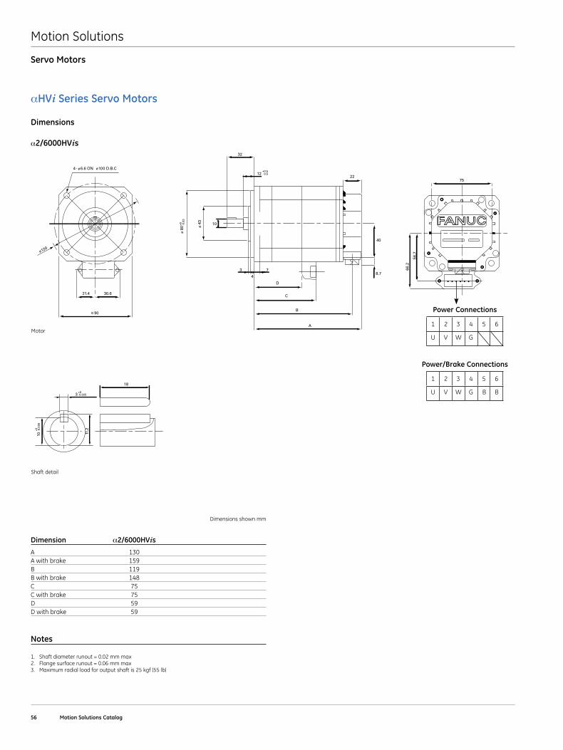
Motion Solutions
56 Motion Solutions Catalog
Servo Motors
αHVi Series Servo Motors
Dimensions
α2/6000HVis
B2/4_4/4iseries_SHAFT.eps
11.2
10
3
18
-0.025+0
-0.0
09+0
5
M5 Depth 12
16
11
-0.030+0
14
23
128
+0.0
01+0
.012
ø
90
21.4 30.6
B2/4_iseries_MOTOR.eps
ø120
4- ø6.6 ON ø100 D.B.C
73
10
32
12
D
C
B
A
4
22
40
8.7
ø 8
0 ø 4
3
-0.0
3+0
-0.5+0.5
66.2
56.7
75
Shaft detail
Motor
Dimensions shown mm
Dimension α2/6000HVis
A 130A with brake 159B 119B with brake 148C 75C with brake 75D 59D with brake 59
Notes
1 . Shaft diameter runout = 0 .02 mm max2 . Flange surface runout = 0 .06 mm max3 . Maximum radial load for output shaft is 25 kgf (55 lb)
1 2 3 4 5
U V W G
6
Power Connections
1 2 3 4 5
U V W G B B
6
Power/Brake Connections
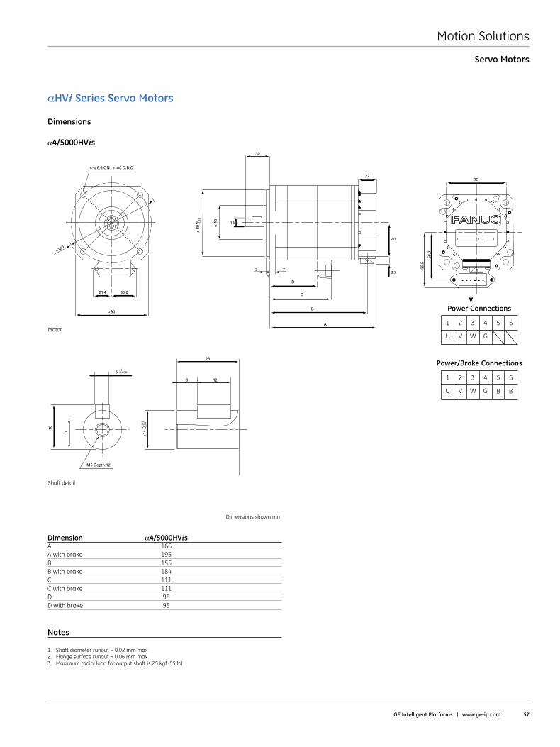
Motion Solutions
GE Intelligent Platforms | www .ge-ip .com 57
Servo Motors
αHVi Series Servo Motors
Dimensions
α4/5000HVis
B2/4_4/4iseries_SHAFT.eps
11.2
10
3
18
-0.025+0
-0.0
09+0
5
M5 Depth 12
16
11
-0.030+0
14
23
128
+0.0
01+0
.012
ø
90
21.4 30.6
B4/4_iseries_MOTOR.eps
ø120
4- ø6.6 ON ø100 D.B.C
7
30
D
C
B
A
22
40
8.7
ø 8
0 ø 4
3
-0.0
3+0
3
4
14
66.2
56.7
75
Shaft detail
Motor
Dimensions shown mm
Dimension α4/5000HVis A 166A with brake 195B 155B with brake 184C 111C with brake 111D 95D with brake 95
Notes
1 . Shaft diameter runout = 0 .02 mm max2 . Flange surface runout = 0 .06 mm max3 . Maximum radial load for output shaft is 25 kgf (55 lb)
1 2 3 4 5
U V W G
6
Power Connections
1 2 3 4 5
U V W G B B
6
Power/Brake Connections
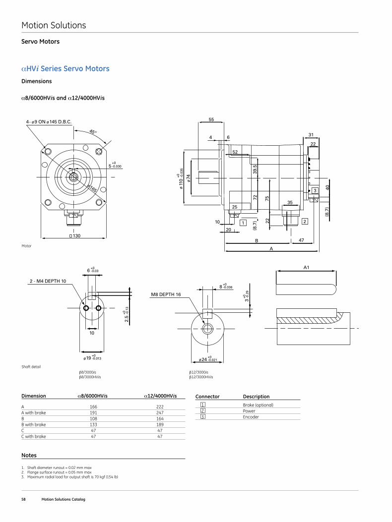
Motion Solutions
58 Motion Solutions Catalog
Servo Motors
αHVi Series Servo MotorsDimensions
α8/6000HVis and α12/4000HVis
Dimension α8/6000HVis α12/4000HVis
A 166 222A with brake 191 247B 108 164B with brake 133 189C 47 47C with brake 47 47
Notes
1 . Shaft diameter runout = 0 .02 mm max2 . Flange surface runout = 0 .05 mm max3 . Maximum radial load for output shaft is 70 kgf (154 lb)
Connector Description
1 Brake (optional) 2 Power 3 Encoder
B8/3_12/3iseries_SHAFT.eps
8
M8 DEPTH 16
24
A1
-0.036+0
3-0
.29
+0
-0.021+0
ø
2.5
10
2 - M4 DEPTH 10
-0.1
3+0
19 -0.013+0
6 -0.03+0
ø
B8/3_12/3iseries_MOTOR.eps
1
B
20
10
A
2
47
3
31
52
6
55
4
40
3525
75
(8.7
)
(8.7
)
22
39.5
72
74
110
22
ø
ø-0
.035
+0
45º
130
5
4- ø9 ON ø145 D.B.C.
ø165
-0.030+0
Shaft detail
Motor
β8/3000isβ8/3000HVis
β12/3000isβ12/3000HVis
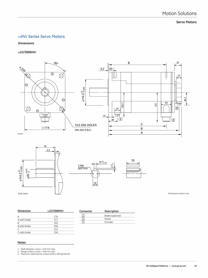
Motion Solutions
GE Intelligent Platforms | www .ge-ip .com 59
Servo Motors
αHVi Series Servo MotorsDimensions
α22/3000HVi
Connector Description
1 Brake (optional) 2 Power 3 Encoder
Dimension α22/3000HVi
A 276A with brake 317B 265B with brake 306C 215C with brake 256
Notes
1 . Shaft diameter runout = 0 .03 mm max2 . Flange surface runout = 0 .06 mm max3 . Maximum radial load for output shaft is 200 kgf (440 lb)
45º ø 230
17413.5 DIA HOLES
ON 200 D.B.C.
12
10
2-M6DEPTH10
127
102.
738
79
20
25
31
22
44
C
B
BA
48.7
ø11
4.3
-0.0
25+0
3-0
.3+0
-0.0 36+0 70
ø11
4.3
ø35
-0.0
25+0 -0+0
.01
3.2
203.2
1 2
3
Shaft detail
Motor
Dimensions shown mm
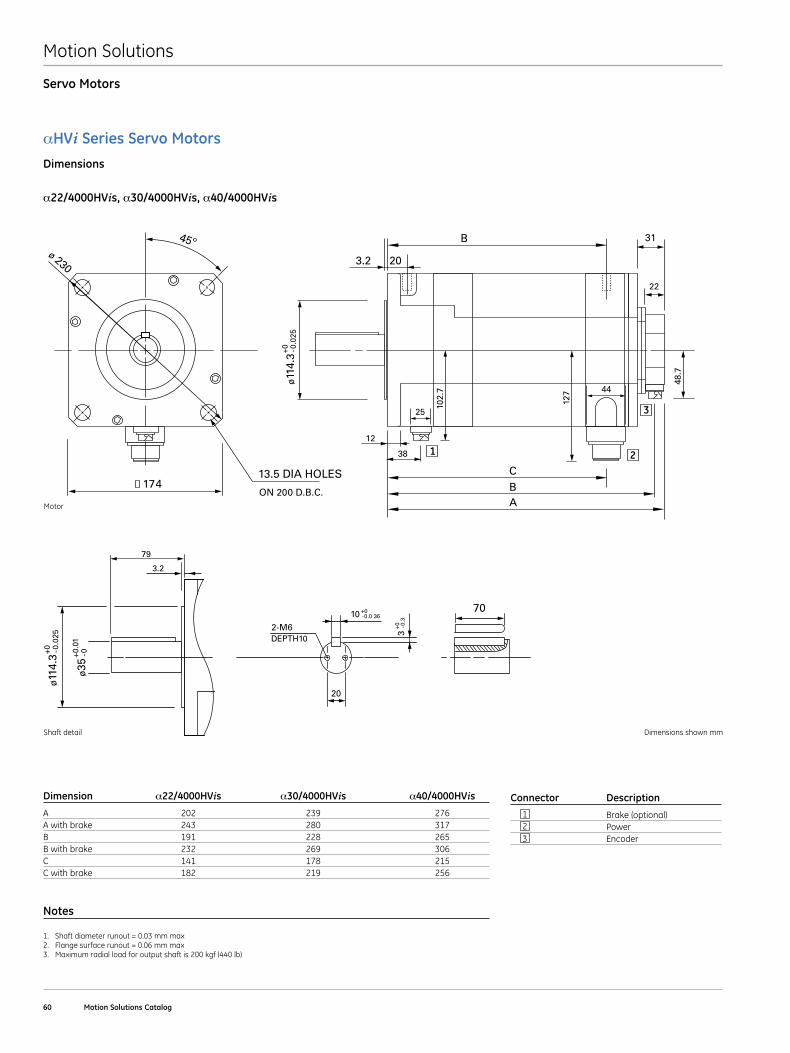
Motion Solutions
60 Motion Solutions Catalog
Servo Motors
αHVi Series Servo MotorsDimensions
α22/4000HVis, α30/4000HVis, α40/4000HVis
Connector Description
1 Brake (optional) 2 Power 3 Encoder
Dimension α22/4000HVis α30/4000HVis α40/4000HVis
A 202 239 276A with brake 243 280 317B 191 228 265B with brake 232 269 306C 141 178 215C with brake 182 219 256
Notes
1 . Shaft diameter runout = 0 .03 mm max2 . Flange surface runout = 0 .06 mm max3 . Maximum radial load for output shaft is 200 kgf (440 lb)
45º ø 230
17413.5 DIA HOLES
ON 200 D.B.C.
12
10
2-M6DEPTH10
127
102.
7
38
79
20
25
31
22
44
C
B
BA
48.7
ø11
4.3
-0.0
25+0
3-0
.3+0
-0.0 36+0 70
ø11
4.3
ø35
-0.0
25+0 -0+0
.01
3.2
203.2
1 2
3
Shaft detail
Motor
Dimensions shown mm
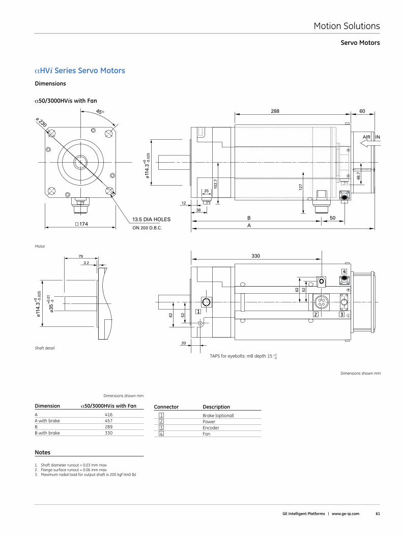
Motion Solutions
GE Intelligent Platforms | www .ge-ip .com 61
Servo Motors
αHVi Series Servo MotorsDimensions
α50/3000HVis with Fan
Dimensions shown mm
Dimension α50/3000HVis with Fan
A 416A with brake 457B 289B with brake 330
Notes
1 . Shaft diameter runout = 0 .03 mm max2 . Flange surface runout = 0 .06 mm max3 . Maximum radial load for output shaft is 200 kgf (440 lb)
Connector Description
1 Brake (optional) 2 Power 3 Encoder 4 Fan
45º ø 230
17413.5 DIA HOLES
ON 200 D.B.C.
12
20
127
102.
738
79
25
B
288
330
60
50
AIR IN
A
48.7
ø11
4.3
-0.0
25+0
ø11
4.3
ø35
-0.0
25+0 -0+0
.01
3.2
62
62 52
52
1 2 3
4
Shaft detail
Motor
Dimensions shown mm
TAPS for eyebolts: m8 depth 15 +1-0
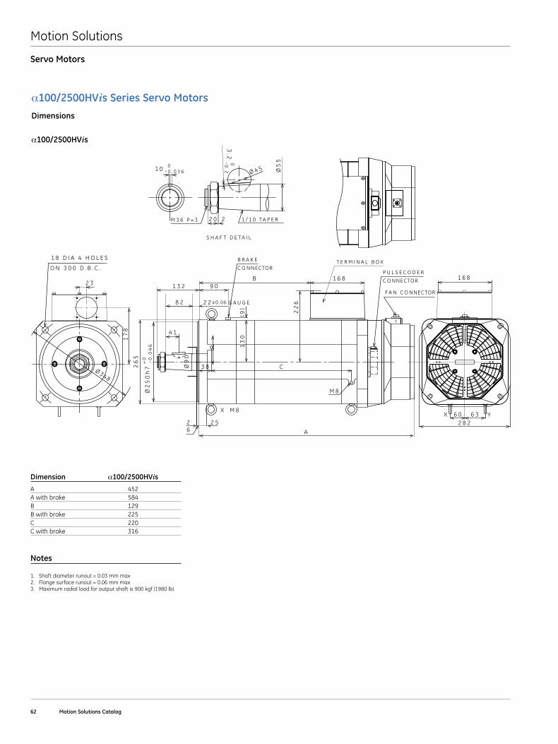
Motion Solutions
62 Motion Solutions Catalog
Servo Motors
α100/2500HVis Series Servo MotorsDimensions
α100/2500HVis
Dimension α100/2500HVis
A 452A with brake 584B 129B with brake 225C 220C with brake 316
Notes
1 . Shaft diameter runout = 0 .03 mm max2 . Flange surface runout = 0 .06 mm max3 . Maximum radial load for output shaft is 900 kgf (1980 lb)
F A N C O NNECTOR
C O NNECTOR
P U L S E C O D E RC O NNECTOR
B R A K E
S H A F T D E T A I L
M 3 6 P = 3
G A U G E
T E R M I N A L B O X
X Y6 0
M 8
X M 86 3
2 8 2
1 6 81 6 8
2 526
9 0
2 2
1 3 2
8 2
2 3
O N 3 0 0 D . B . C .
1 8 D I A 4 H O L E S
C
A
B
3 8Ø9
0
1 0 Ø5
5
26
5
17
8
0- 0 . 0 3 6
3.2
0-0.2
Ø2
50
h7
+0 - 0
.04
6
± 0 . 0 6
(9)
13
0
22
6
2 0 2
4 1
Ø 4 5
1 / 1 0 T A P E R
Ø 348
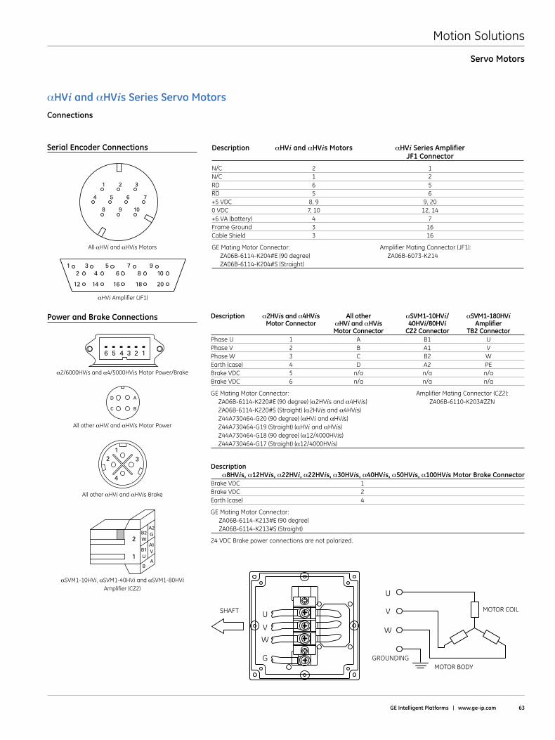
Motion Solutions
GE Intelligent Platforms | www .ge-ip .com 63
Servo Motors
αHVi and αHVis Series Servo MotorsConnections
Description αHVi and αHVis Motors αHVi Series Amplifier JF1 Connector
N/C 2 1N/C 1 2RD 6 5RD 5 6+5 VDC 8, 9 9, 200 VDC 7, 10 12, 14+6 VA (battery) 4 7Frame Ground 3 16Cable Shield 3 16
GE Mating Motor Connector: Amplifier Mating Connector (JF1): ZA06B-6114-K204#E (90 degree) ZA06B-6073-K214 ZA06B-6114-K204#S (Straight)
Description α2HVis and α4HVis All other αSVM1-10HVi/ αSVM1-180HVi Motor Connector αHVi and αHVis 40HVi/80HVi Amplifier Motor Connector CZ2 Connector TB2 ConnectorPhase U 1 A B1 UPhase V 2 B A1 VPhase W 3 C B2 WEarth (case) 4 D A2 PEBrake VDC 5 n/a n/a n/aBrake VDC 6 n/a n/a n/a
GE Mating Motor Connector: Amplifier Mating Connector (CZ2): ZA06B-6114-K220#E (90 degree) (α2HVis and α4HVis) ZA06B-6110-K203#ZZN ZA06B-6114-K220#S (Straight) (α2HVis and α4HVis) Z44A730464-G20 (90 degree) (αHVi and αHVis) Z44A730464-G19 (Straight) (αHVi and αHVis) Z44A730464-G18 (90 degree) (α12/4000HVis) Z44A730464-G17 (Straight) (α12/4000HVis)
Description α8HVis, α12HVis, α22HVi, α22HVis, α30HVis, α40HVis, α50HVis, α100HVis Motor Brake Connector
Brake VDC 1 Brake VDC 2 Earth (case) 4
GE Mating Motor Connector: ZA06B-6114-K213#E (90 degree) ZA06B-6114-K213#S (Straight)
24 VDC Brake power connections are not polarized .
Serial Encoder Connections
Power and Brake Connections
132
4
All αHVi and αHVis Motors
All other αHVi and αHVis Motor Power
All other αHVi and αHVis Brake
αSVM1-10HVi, αSVM1-40HVi and αSVM1-80HVi Amplifier (CZ2)
A
BC
D
1 2 3
8 9 10
4 5 6 7
αHVi Amplifier (JF1)
3 5 7 94 6 8 10
14 16 18 20
12
12
2B2W
B1U
BA
A1V
A2G
1
6 5 4 3 2 1
α2/6000HVis and α4/5000HVis Motor Power/Brake
U
V
W
U
G
V
W
GROUNDING
SHAFT
MOTOR BODY
MOTOR COIL
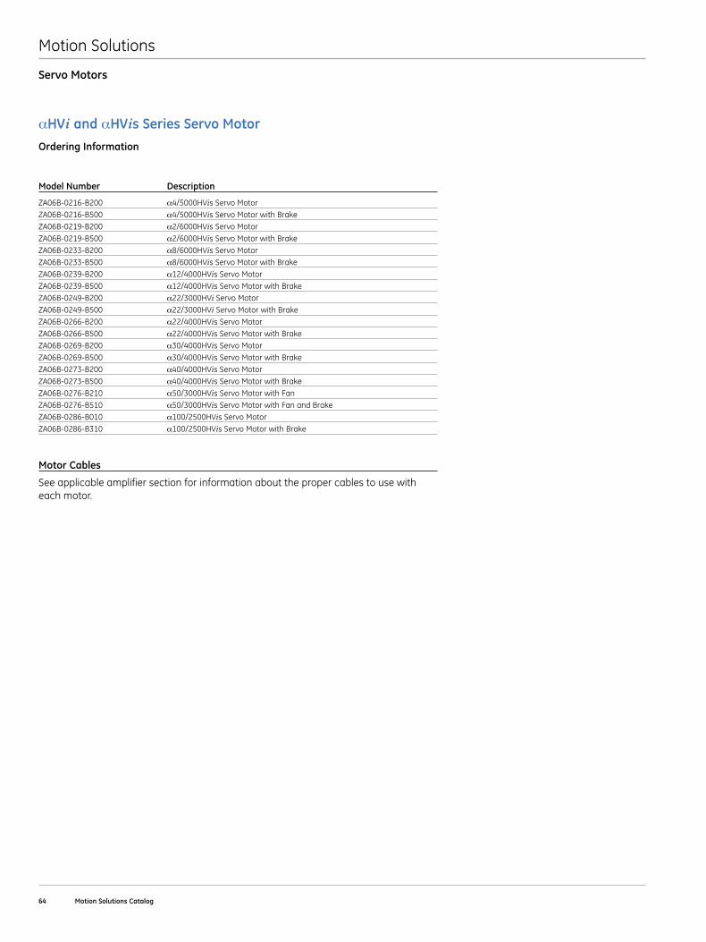
Motion Solutions
64 Motion Solutions Catalog
Servo Motors
αHVi and αHVis Series Servo MotorOrdering Information
Motor Cables
See applicable amplifier section for information about the proper cables to use with each motor .
Model Number Description
ZA06B-0216-B200 α4/5000HVis Servo MotorZA06B-0216-B500 α4/5000HVis Servo Motor with BrakeZA06B-0219-B200 α2/6000HVis Servo MotorZA06B-0219-B500 α2/6000HVis Servo Motor with BrakeZA06B-0233-B200 α8/6000HVis Servo MotorZA06B-0233-B500 α8/6000HVis Servo Motor with BrakeZA06B-0239-B200 α12/4000HVis Servo MotorZA06B-0239-B500 α12/4000HVis Servo Motor with BrakeZA06B-0249-B200 α22/3000HVi Servo MotorZA06B-0249-B500 α22/3000HVi Servo Motor with BrakeZA06B-0266-B200 α22/4000HVis Servo MotorZA06B-0266-B500 α22/4000HVis Servo Motor with BrakeZA06B-0269-B200 α30/4000HVis Servo MotorZA06B-0269-B500 α30/4000HVis Servo Motor with BrakeZA06B-0273-B200 α40/4000HVis Servo MotorZA06B-0273-B500 α40/4000HVis Servo Motor with BrakeZA06B-0276-B210 α50/3000HVis Servo Motor with FanZA06B-0276-B510 α50/3000HVis Servo Motor with Fan and BrakeZA06B-0286-B010 α100/2500HVis Servo MotorZA06B-0286-B310 α100/2500HVis Servo Motor with Brake
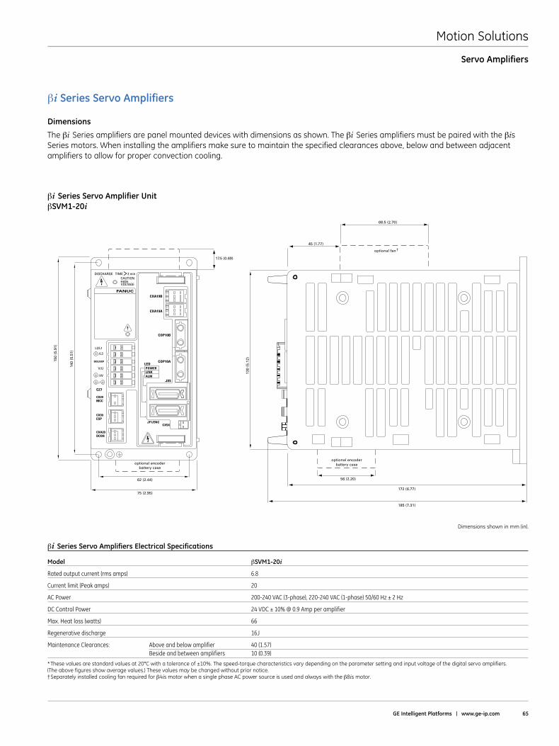
Motion Solutions
GE Intelligent Platforms | www .ge-ip .com 65
Servo Amplifiers
DISCHARGE TIMECAUTIONHIGHVOLTAGE
L2/L1
/L3
DCC/DCP
/W
V/U
CZ7
CX29 MCC
CX30 ESP
CXA20 DCOH
CXA19B
CXA19A
COP10B
COP10ALEDPOWERLINKALM
JF1/ENCCX5X
JX5
2 min
FANUC
>
130
(5.
12)
150
(5.9
1)
140
(5.5
1)
45 (1.77)
68.5 (2.70)
172 (6.77)
185 (7.31)
optional fan
optional encoderbattery caseoptional encoder
battery case
56 (2.20)62 (2.44)
75 (2.95)
17.5 (0.69)
†
βi Series Servo Amplifiers
Dimensions
The βi Series amplifiers are panel mounted devices with dimensions as shown . The βi Series amplifiers must be paired with the βis Series motors . When installing the amplifiers make sure to maintain the specified clearances above, below and between adjacent amplifiers to allow for proper convection cooling .
Dimensions shown in mm (in) .
βi Series Servo Amplifier UnitβSVM1-20i
βi Series Servo Amplifiers Electrical Specifications
Model βSVM1-20i
Rated output current (rms amps) 6.8
Current limit (Peak amps) 20
AC Power 200-240 VAC (3-phase), 220-240 VAC (1-phase) 50/60 Hz ± 2 Hz
DC Control Power 24 VDC ± 10% @ 0.9 Amp per amplifier
Max. Heat loss (watts) 66
Regenerative discharge 16J
Maintenance Clearances: Above and below amplifier 40 (1.57) Beside and between amplifiers 10 (0.39)
*Thesevaluesarestandardvaluesat20°Cwithatoleranceof±10%.Thespeed-torquecharacteristicsvarydependingontheparametersettingandinputvoltageofthedigitalservoamplifiers. (The above figures show average values .) These values may be changed without prior notice .†Separately installed cooling fan required for β4is motor when a single phase AC power source is used and always with the β8is motor .

Motion Solutions
66 Motion Solutions Catalog
Servo Amplifiers
Dimensions shown in mm (in) .
CAUTION
CAUTIONHIGHVOLTAGE DISCHARGE TIME >2 min
C24 (FRONT) C25 (CENTER) C26 (REAR)
FANUC
FANUC LTDYamenashi 401-0597 JAPAN
LEDPOWERLINKALM
C24 C25
CX5 X
SW
JF1/ENC
C26PULL HERE
A L2 V RI RCL1 W U RCREL3B
BATTERY
OPTIONALENCODER BATTERY
CASE
CX29 MCC
CX30 ESP
CXA20 DCOH
CXA19B
CXA19A
COP10B
COP10A
JX5
172 (6.77)
10 (0.39)
100 (3.94) max.
mounting flange
380
(14.
96)
360
(14.
17)
60 (2.36)
30 (1.18)
βi Series Servo Amplifiers
Dimensions
The βi Series amplifiers are panel mounted devices with dimensions as shown . The βi Series amplifiers must be paired with the βis Series motors . When installing the amplifiers make sure to maintain the specified clearances above, below and between adjacent amplifiers to allow for proper convection cooling .
βi Series Servo Amplifier UnitβSVM1-40iβSVM1-10HViβSVM1-40HVi
βi Series Servo Amplifiers Electrical Specifications
Model βSVM1-40i βSVM1-10HVi βSVM1-20HVi βSVM1-40HVi
Rated output current (rms amps) 12 3.1 5.6 9.2
Current limit (Peak amps) 40 10 20 40
AC Power 1-phase n/a n/a n/a n/a 3-phase 200-240 VAC, 50/60 Hz ± 2 Hz 400-480 VAC 400-480 VAC 400-480 VAC
DC Control Power (per amplifier) 24 VDC ± 10% @ 0.9 Amp 24 VDC ± 10% @ 0.9 Amp 24 VDC ± 10% @ 0.9 Amp 24 VDC ± 10% @ 0.9 Amp
Max. Heat loss (watts) 100 54 82 122
Regenerative discharge 50W 50W 50W 50W
Maintenance Clearances: Above and below amplifier 50 (1.97) 50 (1.97) 50 (1.97) 50 (1.97) Beside and between amplifiers n/a n/a n/a n/a
*Thesevaluesarestandardvaluesat20°Cwithatoleranceof±10%.Thespeed-torquecharacteristicsvarydependingontheparametersettingandinputvoltageofthedigitalservoamplifiers. (The above figures show average values .) These values may be changed without prior notice .
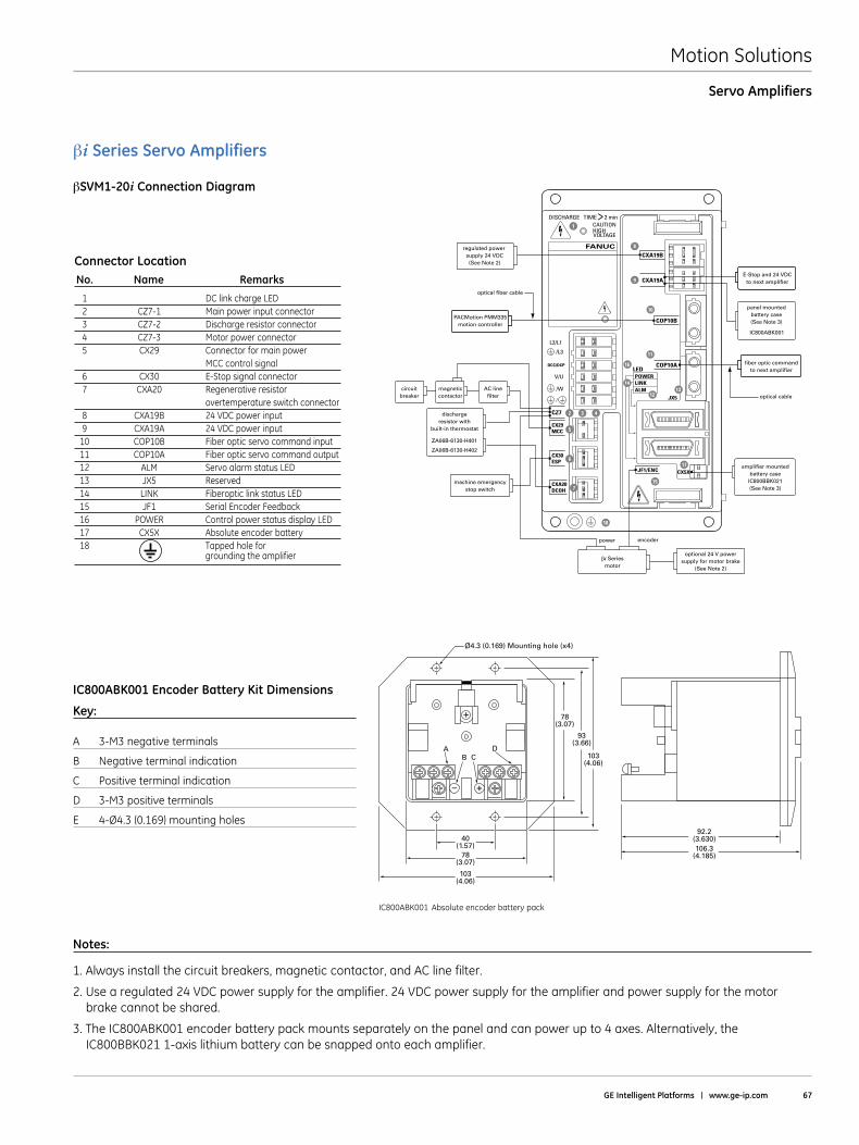
Motion Solutions
GE Intelligent Platforms | www .ge-ip .com 67
Servo Amplifiers
βi Series Servo Amplifiers
βSVM1-20i Connection Diagram
Notes:
1 . Always install the circuit breakers, magnetic contactor, and AC line filter .
2 . Use a regulated 24 VDC power supply for the amplifier . 24 VDC power supply for the amplifier and power supply for the motor brake cannot be shared .
3 . The IC800ABK001 encoder battery pack mounts separately on the panel and can power up to 4 axes . Alternatively, the IC800BBK021 1-axis lithium battery can be snapped onto each amplifier .
DISCHARGE TIMECAUTIONHIGHVOLTAGE
L2/L1
/L3
DCC/DCP
/W
V/U
CZ7
CX29MCC
CX30ESP
CXA20DCOH
CXA19B
CXA19A
COP10B
COP10ALEDPOWERLINKALM
JF1/ENC CX5X
JX5
2 min
FANUC
>
optical cable
optical fiber cable
regulated power supply 24 VDC(See Note 2)
PACMotion PMM335motion controller
AC linefilter
circuitbreaker
magneticcontactor
dischargeresistor with
built-in thermostat
ZA06B-6130-H401
ZA06B-6130-H402
machine emergencystop switch
E-Stop and 24 VDCto next amplifier
fiber optic commandto next amplifier
panel mountedbattery case(See Note 3)
IC800ABK001
1
8
9
10
11
12
15
16
18
1314
2
5
6
7
3 4
power
βi Seriesmotor
optional 24 V powersupply for motor brake
(See Note 2)
encoder
amplifier mountedbattery case
IC800BBK021(See Note 3)
17
Connector Location No . Name Remarks
1 DC link charge LED 2 CZ7-1 Main power input connector 3 CZ7-2 Discharge resistor connector 4 CZ7-3 Motor power connector 5 CX29 Connector for main power MCC control signal 6 CX30 E-Stop signal connector 7 CXA20 Regenerative resistor overtemperature switch connector 8 CXA19B 24 VDC power input 9 CXA19A 24 VDC power input 10 COP10B Fiber optic servo command input 11 COP10A Fiber optic servo command output 12 ALM Servo alarm status LED 13 JX5 Reserved 14 LINK Fiberoptic link status LED 15 JF1 Serial Encoder Feedback 16 POWER Control power status display LED 17 CX5X Absolute encoder battery 18 Tapped hole for grounding the amplifier
AB C
D
+–
+
40(1.57)
78(3.07)
103(4.06)
103(4.06)
78(3.07)
Ø4.3 (0.169) Mounting hole (x4)
93(3.66)
92.2(3.630)106.3
(4.185)
DIM_aSeriesBatteryPk.eps
file name: DIM_aSeriesBatteryPk.eps
current page in catalog: 45
source: GFH-001 pg 13
file name: DIM_aSeriesBatteryPk.eps
current page in catalog: 45
source: GFH-001 pg 13
IC800ABK001 Absolute encoder battery pack
IC800ABK001 Encoder Battery Kit Dimensions
Key:
A 3-M3 negative terminals
B Negative terminal indication
C Positive terminal indication
D 3-M3 positive terminals
E 4-Ø4 .3 (0 .169) mounting holes
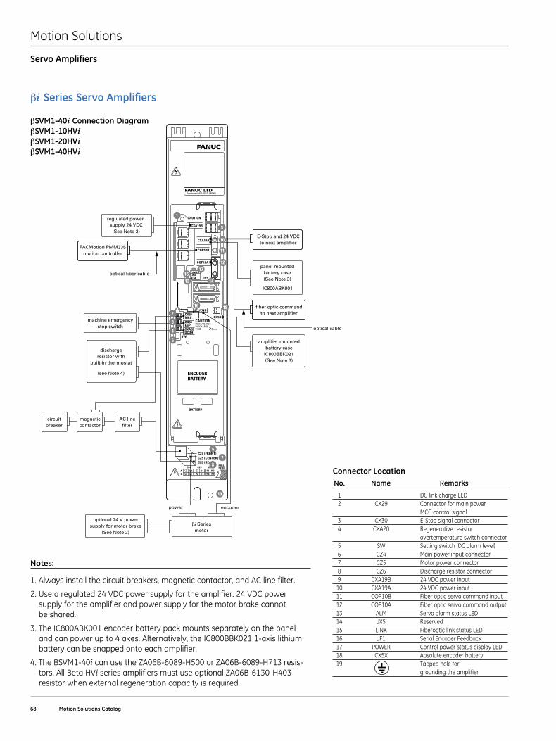
Motion Solutions
68 Motion Solutions Catalog
Servo Amplifiers
βi Series Servo Amplifiers
βSVM1-40i Connection DiagramβSVM1-10HVi βSVM1-20HVi βSVM1-40HVi
power
optical fiber cable
regulated power supply 24 VDC(See Note 2)
dischargeresistor with
built-in thermostat
(see Note 4)
machine emergencystop switch
βi Seriesmotor
optional 24 V powersupply for motor brake
(See Note 2)
E-Stop and 24 VDCto next amplifier
fiber optic commandto next amplifier
panel mountedbattery case(See Note 3)
optical cable
IC800ABK001
1
9
11
12
16 18
19
14
2
5
6
7
AC linefilter
circuitbreaker
magneticcontactor
10
encoder
PACMotion PMM335motion controller
amplifier mountedbattery case
IC800BBK021(See Note 3)
3
4
CAUTION
CAUTIONHIGHVOLTAGEDISCHARGE TIME >2 min
CZ4 (FRONT)CZ5 (CENTER)CZ6 (REAR)
FANUC
FANUC LTDYamenashi 401-0597 JAPAN
LEDPOWERLINKALM
C24 C25
SW
JF1/ENC
C26PULLHERE
A L2 V RI RCL1 W U RCREL3B
BATTERY
ENCODERBATTERY
CX29MCCCX30ESPCXA20DCOH
CXA19B
COP10B
COP10A
JX5
CXA19A
CX5X
1315
17
8
Notes:
1 . Always install the circuit breakers, magnetic contactor, and AC line filter .
2 . Use a regulated 24 VDC power supply for the amplifier . 24 VDC power supply for the amplifier and power supply for the motor brake cannot be shared .
3 . The IC800ABK001 encoder battery pack mounts separately on the panel and can power up to 4 axes . Alternatively, the IC800BBK021 1-axis lithium battery can be snapped onto each amplifier .
4 . The BSVM1-40i can use the ZA06B-6089-H500 or ZA06B-6089-H713 resis-tors . All Beta HVi series amplifiers must use optional ZA06B-6130-H403 resistor when external regeneration capacity is required .
Connector Location No . Name Remarks
1 DC link charge LED 2 CX29 Connector for main power MCC control signal 3 CX30 E-Stop signal connector 4 CXA20 Regenerative resistor overtemperature switch connector 5 SW Setting switch (DC alarm level) 6 CZ4 Main power input connector 7 CZ5 Motor power connector 8 CZ6 Discharge resistor connector 9 CXA19B 24 VDC power input 10 CXA19A 24 VDC power input 11 COP10B Fiber optic servo command input 12 COP10A Fiber optic servo command output 13 ALM Servo alarm status LED 14 JX5 Reserved 15 LINK Fiberoptic link status LED 16 JF1 Serial Encoder Feedback 17 POWER Control power status display LED 18 CX5X Absolute encoder battery 19 Tapped hole for grounding the amplifier
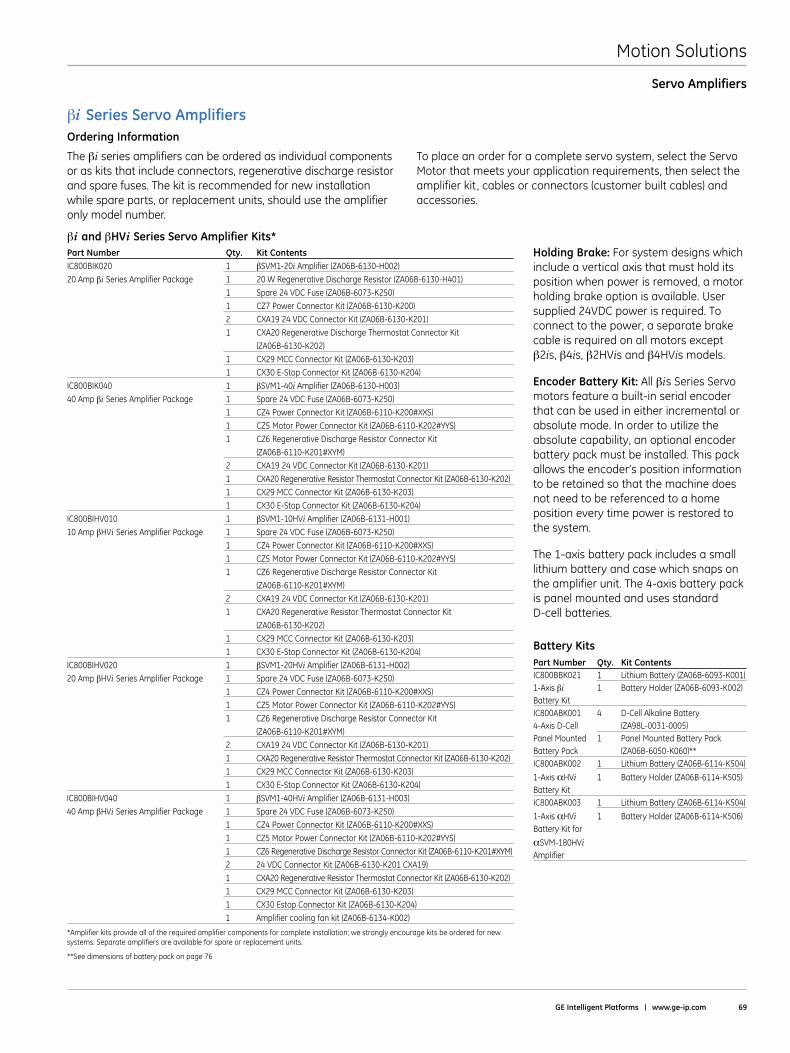
Motion Solutions
GE Intelligent Platforms | www .ge-ip .com 69
Servo Amplifiers
The βiseries amplifiers can be ordered as individual components or as kits that include connectors, regenerative discharge resistor and spare fuses . The kit is recommended for new installation while spare parts, or replacement units, should use the amplifier only model number .
To place an order for a complete servo system, select the Servo Motor that meets your application requirements, then select the amplifier kit, cables or connectors (customer built cables) and accessories .
βiand βHVi Series Servo Amplifier Kits*Part Number Qty . Kit ContentsIC800BIK020 1 βSVM1-20i Amplifier (ZA06B-6130-H002)20 Amp βi Series Amplifier Package 1 20 W Regenerative Discharge Resistor (ZA06B-6130-H401) 1 Spare 24 VDC Fuse (ZA06B-6073-K250) 1 CZ7 Power Connector Kit (ZA06B-6130-K200) 2 CXA19 24 VDC Connector Kit (ZA06B-6130-K201) 1 CXA20 Regenerative Discharge Thermostat Connector Kit (ZA06B-6130-K202) 1 CX29 MCC Connector Kit (ZA06B-6130-K203) 1 CX30 E-Stop Connector Kit (ZA06B-6130-K204)IC800BIK040 1 βSVM1-40i Amplifier (ZA06B-6130-H003)40 Amp βi Series Amplifier Package 1 Spare 24 VDC Fuse (ZA06B-6073-K250) 1 CZ4 Power Connector Kit (ZA06B-6110-K200#XXS) 1 CZ5 Motor Power Connector Kit (ZA06B-6110-K202#YYS) 1 CZ6 Regenerative Discharge Resistor Connector Kit (ZA06B-6110-K201#XYM) 2 CXA19 24 VDC Connector Kit (ZA06B-6130-K201) 1 CXA20 Regenerative Resistor Thermostat Connector Kit (ZA06B-6130-K202) 1 CX29 MCC Connector Kit (ZA06B-6130-K203) 1 CX30 E-Stop Connector Kit (ZA06B-6130-K204)IC800BIHV010 1 βSVM1-10HVi Amplifier (ZA06B-6131-H001)10 Amp βHVi Series Amplifier Package 1 Spare 24 VDC Fuse (ZA06B-6073-K250) 1 CZ4 Power Connector Kit (ZA06B-6110-K200#XXS) 1 CZ5 Motor Power Connector Kit (ZA06B-6110-K202#YYS) 1 CZ6 Regenerative Discharge Resistor Connector Kit (ZA06B-6110-K201#XYM) 2 CXA19 24 VDC Connector Kit (ZA06B-6130-K201) 1 CXA20 Regenerative Resistor Thermostat Connector Kit (ZA06B-6130-K202) 1 CX29 MCC Connector Kit (ZA06B-6130-K203) 1 CX30 E-Stop Connector Kit (ZA06B-6130-K204)IC800BIHV020 1 βSVM1-20HVi Amplifier (ZA06B-6131-H002)20 Amp βHVi Series Amplifier Package 1 Spare 24 VDC Fuse (ZA06B-6073-K250) 1 CZ4 Power Connector Kit (ZA06B-6110-K200#XXS) 1 CZ5 Motor Power Connector Kit (ZA06B-6110-K202#YYS) 1 CZ6 Regenerative Discharge Resistor Connector Kit (ZA06B-6110-K201#XYM) 2 CXA19 24 VDC Connector Kit (ZA06B-6130-K201) 1 CXA20 Regenerative Resistor Thermostat Connector Kit (ZA06B-6130-K202) 1 CX29 MCC Connector Kit (ZA06B-6130-K203) 1 CX30 E-Stop Connector Kit (ZA06B-6130-K204)IC800BIHV040 1 βSVM1-40HVi Amplifier (ZA06B-6131-H003)40 Amp βHVi Series Amplifier Package 1 Spare 24 VDC Fuse (ZA06B-6073-K250) 1 CZ4 Power Connector Kit (ZA06B-6110-K200#XXS) 1 CZ5 Motor Power Connector Kit (ZA06B-6110-K202#YYS) 1 CZ6 Regenerative Discharge Resistor Connector Kit (ZA06B-6110-K201#XYM) 2 24 VDC Connector Kit (ZA06B-6130-K201 CXA19) 1 CXA20 Regenerative Resistor Thermostat Connector Kit (ZA06B-6130-K202) 1 CX29 MCC Connector Kit (ZA06B-6130-K203) 1 CX30 Estop Connector Kit (ZA06B-6130-K204) 1 Amplifier cooling fan kit (ZA06B-6134-K002)
*Amplifier kits provide all of the required amplifier components for complete installation; we strongly encourage kits be ordered for new systems . Separate amplifiers are available for spare or replacement units .
**See dimensions of battery pack on page 76
Holding Brake: For system designs which include a vertical axis that must hold its position when power is removed, a motor holding brake option is available . User supplied 24VDC power is required . To connect to the power, a separate brake cable is required on all motors except β2is, β4is, β2HVis and β4HVis models .
Encoder Battery Kit: All βis Series Servo motors feature a built-in serial encoder that can be used in either incremental or absolute mode . In order to utilize the absolute capability, an optional encoder battery pack must be installed . This pack allows the encoder’s position information to be retained so that the machine does not need to be referenced to a home position every time power is restored to the system .
The 1-axis battery pack includes a small lithium battery and case which snaps on the amplifier unit . The 4-axis battery pack is panel mounted and uses standard D-cell batteries .
βi Series Servo AmplifiersOrdering Information
Battery KitsPart Number Qty . Kit ContentsIC800BBK021 1 Lithium Battery (ZA06B-6093-K001)1-Axis βi 1 Battery Holder (ZA06B-6093-K002)Battery Kit IC800ABK001 4 D-Cell Alkaline Battery4-Axis D-Cell (ZA98L-0031-0005)Panel Mounted 1 Panel Mounted Battery PackBattery Pack (ZA06B-6050-K060)**IC800ABK002 1 Lithium Battery (ZA06B-6114-K504)
1-Axis αHVi 1 Battery Holder (ZA06B-6114-K505) Battery KitIC800ABK003 1 Lithium Battery (ZA06B-6114-K504)
1-Axis αHVi 1 Battery Holder (ZA06B-6114-K506) Battery Kit for
αSVM-180HViAmplifier
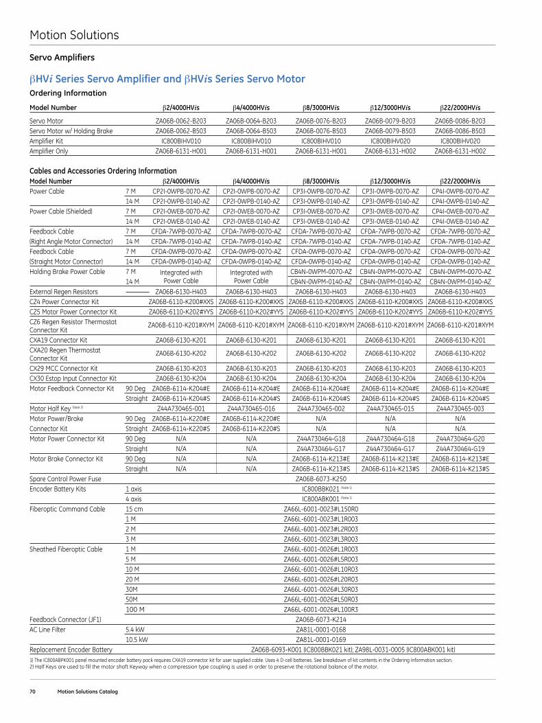
Motion Solutions
70 Motion Solutions Catalog
Servo Amplifiers
βHVi Series Servo Amplifier and βHVis Series Servo Motor Ordering Information
Model Number β2/4000HVis β4/4000HVis β8/3000HVis β12/3000HVis β22/2000HVis
Servo Motor ZA06B-0062-B203 ZA06B-0064-B203 ZA06B-0076-B203 ZA06B-0079-B203 ZA06B-0086-B203Servo Motor w/ Holding Brake ZA06B-0062-B503 ZA06B-0064-B503 ZA06B-0076-B503 ZA06B-0079-B503 ZA06B-0086-B503Amplifier Kit IC800BIHV010 IC800BIHV010 IC800BIHV010 IC800BIHV020 IC800BIHV020Amplifier Only ZA06B-6131-H001 ZA06B-6131-H001 ZA06B-6131-H001 ZA06B-6131-H002 ZA06B-6131-H002
Cables and Accessories Ordering InformationModel Number β2/4000HVis β4/4000HVis β8/3000HVis β12/3000HVis β22/2000HVisPower Cable 7 M CP2I-0WPB-0070-AZ CP2I-0WPB-0070-AZ CP3I-0WPB-0070-AZ CP3I-0WPB-0070-AZ CP4I-0WPB-0070-AZ 14 M CP2I-0WPB-0140-AZ CP2I-0WPB-0140-AZ CP3I-0WPB-0140-AZ CP3I-0WPB-0140-AZ CP4I-0WPB-0140-AZPower Cable (Shielded) 7 M CP2I-0WEB-0070-AZ CP2I-0WEB-0070-AZ CP3I-0WEB-0070-AZ CP3I-0WEB-0070-AZ CP4I-0WEB-0070-AZ 14 M CP2I-0WEB-0140-AZ CP2I-0WEB-0140-AZ CP3I-0WEB-0140-AZ CP3I-0WEB-0140-AZ CP4I-0WEB-0140-AZFeedback Cable 7 M CFDA-7WPB-0070-AZ CFDA-7WPB-0070-AZ CFDA-7WPB-0070-AZ CFDA-7WPB-0070-AZ CFDA-7WPB-0070-AZ(Right Angle Motor Connector) 14 M CFDA-7WPB-0140-AZ CFDA-7WPB-0140-AZ CFDA-7WPB-0140-AZ CFDA-7WPB-0140-AZ CFDA-7WPB-0140-AZFeedback Cable 7 M CFDA-0WPB-0070-AZ CFDA-0WPB-0070-AZ CFDA-0WPB-0070-AZ CFDA-0WPB-0070-AZ CFDA-0WPB-0070-AZ(Straight Motor Connector) 14 M CFDA-0WPB-0140-AZ CFDA-0WPB-0140-AZ CFDA-0WPB-0140-AZ CFDA-0WPB-0140-AZ CFDA-0WPB-0140-AZHolding Brake Power Cable 7 M Integrated with Integrated with CB4N-0WPM-0070-AZ CB4N-0WPM-0070-AZ CB4N-0WPM-0070-AZ 14 M Power Cable Power Cable CB4N-0WPM-0140-AZ CB4N-0WPM-0140-AZ CB4N-0WPM-0140-AZExternal Regen Resistors ZA06B-6130-H403 ZA06B-6130-H403 ZA06B-6130-H403 ZA06B-6130-H403 ZA06B-6130-H403CZ4 Power Connector Kit ZA06B-6110-K200#XXS ZA06B-6110-K200#XXS ZA06B-6110-K200#XXS ZA06B-6110-K200#XXS ZA06B-6110-K200#XXSCZ5 Motor Power Connector Kit ZA06B-6110-K202#YYS ZA06B-6110-K202#YYS ZA06B-6110-K202#YYS ZA06B-6110-K202#YYS ZA06B-6110-K202#YYSCZ6 Regen Resistor Thermostat ZA06B-6110-K201#XYM ZA06B-6110-K201#XYM ZA06B-6110-K201#XYM ZA06B-6110-K201#XYM ZA06B-6110-K201#XYMConnector KitCXA19 Connector Kit ZA06B-6130-K201 ZA06B-6130-K201 ZA06B-6130-K201 ZA06B-6130-K201 ZA06B-6130-K201CXA20 Regen Thermostat ZA06B-6130-K202 ZA06B-6130-K202 ZA06B-6130-K202 ZA06B-6130-K202 ZA06B-6130-K202Connector KitCX29 MCC Connector Kit ZA06B-6130-K203 ZA06B-6130-K203 ZA06B-6130-K203 ZA06B-6130-K203 ZA06B-6130-K203CX30 Estop Input Connector Kit ZA06B-6130-K204 ZA06B-6130-K204 ZA06B-6130-K204 ZA06B-6130-K204 ZA06B-6130-K204Motor Feedback Connector Kit 90 Deg ZA06B-6114-K204#E ZA06B-6114-K204#E ZA06B-6114-K204#E ZA06B-6114-K204#E ZA06B-6114-K204#E Straight ZA06B-6114-K204#S ZA06B-6114-K204#S ZA06B-6114-K204#S ZA06B-6114-K204#S ZA06B-6114-K204#SMotor Half Key (Note 2) Z44A730465-001 Z44A730465-016 Z44A730465-002 Z44A730465-015 Z44A730465-003Motor Power/Brake 90 Deg ZA06B-6114-K220#E ZA06B-6114-K220#E N/A N/A N/AConnector Kit Straight ZA06B-6114-K220#S ZA06B-6114-K220#S N/A N/A N/AMotor Power Connector Kit 90 Deg N/A N/A Z44A730464-G18 Z44A730464-G18 Z44A730464-G20 Straight N/A N/A Z44A730464-G17 Z44A730464-G17 Z44A730464-G19Motor Brake Connector Kit 90 Deg N/A N/A ZA06B-6114-K213#E ZA06B-6114-K213#E ZA06B-6114-K213#E Straight N/A N/A ZA06B-6114-K213#S ZA06B-6114-K213#S ZA06B-6114-K213#SSpare Control Power Fuse ZA06B-6073-K250Encoder Battery Kits 1 axis IC800BBK021 (Note 1)
4 axis IC800ABK001 (Note 1)
Fiberoptic Command Cable 15 cm ZA66L-6001-0023#L150R0 1 M ZA66L-6001-0023#L1R003 2 M ZA66L-6001-0023#L2R003 3 M ZA66L-6001-0023#L3R003Sheathed Fiberoptic Cable 1 M ZA66L-6001-0026#L1R003 5 M ZA66L-6001-0026#L5R003 10 M ZA66L-6001-0026#L10R03 20 M ZA66L-6001-0026#L20R03 30M ZA66L-6001-0026#L30R03 50M ZA66L-6001-0026#L50R03 100 M ZA66L-6001-0026#L100R3Feedback Connector (JF1) ZA06B-6073-K214AC Line Filter 5 .4 kW ZA81L-0001-0168 10 .5 kW ZA81L-0001-0169Replacement Encoder Battery ZA06B-6093-K001 (IC800BBK021 kit); ZA98L-0031-0005 (IC800ABK001 kit)1) The IC800ABPK001 panel mounted encoder battery pack requires CXA19 connector kit for user supplied cable . Uses 4 D-cell batteries . See breakdown of kit contents in the Ordering Information section .2) Half Keys are used to fill the motor shaft Keyway when a compression type coupling is used in order to preserve the rotational balance of the motor .
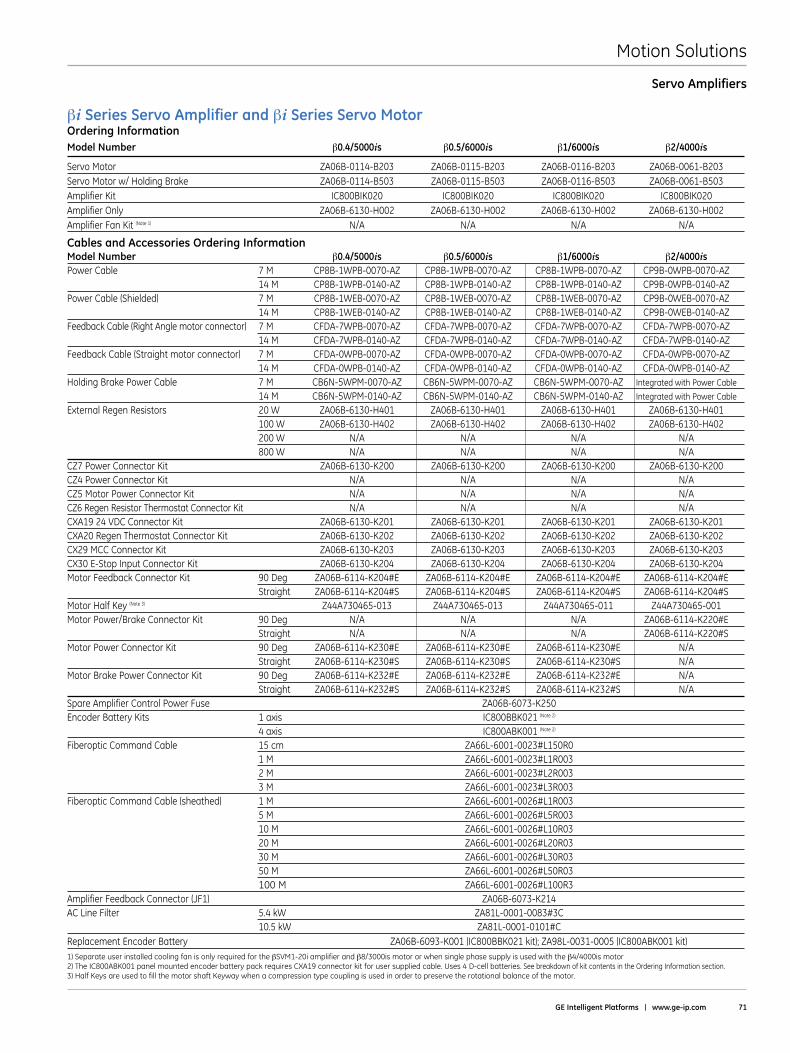
Motion Solutions
GE Intelligent Platforms | www .ge-ip .com 71
Servo Amplifiers
βi Series Servo Amplifier and βi Series Servo MotorOrdering InformationModel Number β0 .4/5000is β0 .5/6000is β1/6000is β2/4000is
Servo Motor ZA06B-0114-B203 ZA06B-0115-B203 ZA06B-0116-B203 ZA06B-0061-B203Servo Motor w/ Holding Brake ZA06B-0114-B503 ZA06B-0115-B503 ZA06B-0116-B503 ZA06B-0061-B503Amplifier Kit IC800BIK020 IC800BIK020 IC800BIK020 IC800BIK020Amplifier Only ZA06B-6130-H002 ZA06B-6130-H002 ZA06B-6130-H002 ZA06B-6130-H002Amplifier Fan Kit (Note 1) N/A N/A N/A N/A
Cables and Accessories Ordering InformationModel Number β0 .4/5000is β0 .5/6000is β1/6000is β2/4000isPower Cable 7 M CP8B-1WPB-0070-AZ CP8B-1WPB-0070-AZ CP8B-1WPB-0070-AZ CP9B-0WPB-0070-AZ 14 M CP8B-1WPB-0140-AZ CP8B-1WPB-0140-AZ CP8B-1WPB-0140-AZ CP9B-0WPB-0140-AZPower Cable (Shielded) 7 M CP8B-1WEB-0070-AZ CP8B-1WEB-0070-AZ CP8B-1WEB-0070-AZ CP9B-0WEB-0070-AZ 14 M CP8B-1WEB-0140-AZ CP8B-1WEB-0140-AZ CP8B-1WEB-0140-AZ CP9B-0WEB-0140-AZFeedback Cable (Right Angle motor connector) 7 M CFDA-7WPB-0070-AZ CFDA-7WPB-0070-AZ CFDA-7WPB-0070-AZ CFDA-7WPB-0070-AZ 14 M CFDA-7WPB-0140-AZ CFDA-7WPB-0140-AZ CFDA-7WPB-0140-AZ CFDA-7WPB-0140-AZFeedback Cable (Straight motor connector) 7 M CFDA-0WPB-0070-AZ CFDA-0WPB-0070-AZ CFDA-0WPB-0070-AZ CFDA-0WPB-0070-AZ 14 M CFDA-0WPB-0140-AZ CFDA-0WPB-0140-AZ CFDA-0WPB-0140-AZ CFDA-0WPB-0140-AZHolding Brake Power Cable 7 M CB6N-5WPM-0070-AZ CB6N-5WPM-0070-AZ CB6N-5WPM-0070-AZ Integrated with Power Cable
14 M CB6N-5WPM-0140-AZ CB6N-5WPM-0140-AZ CB6N-5WPM-0140-AZ Integrated with Power Cable
External Regen Resistors 20 W ZA06B-6130-H401 ZA06B-6130-H401 ZA06B-6130-H401 ZA06B-6130-H401 100 W ZA06B-6130-H402 ZA06B-6130-H402 ZA06B-6130-H402 ZA06B-6130-H402 200 W N/A N/A N/A N/A 800 W N/A N/A N/A N/ACZ7 Power Connector Kit ZA06B-6130-K200 ZA06B-6130-K200 ZA06B-6130-K200 ZA06B-6130-K200CZ4 Power Connector Kit N/A N/A N/A N/ACZ5 Motor Power Connector Kit N/A N/A N/A N/ACZ6 Regen Resistor Thermostat Connector Kit N/A N/A N/A N/ACXA19 24 VDC Connector Kit ZA06B-6130-K201 ZA06B-6130-K201 ZA06B-6130-K201 ZA06B-6130-K201CXA20 Regen Thermostat Connector Kit ZA06B-6130-K202 ZA06B-6130-K202 ZA06B-6130-K202 ZA06B-6130-K202CX29 MCC Connector Kit ZA06B-6130-K203 ZA06B-6130-K203 ZA06B-6130-K203 ZA06B-6130-K203CX30 E-Stop Input Connector Kit ZA06B-6130-K204 ZA06B-6130-K204 ZA06B-6130-K204 ZA06B-6130-K204Motor Feedback Connector Kit 90 Deg ZA06B-6114-K204#E ZA06B-6114-K204#E ZA06B-6114-K204#E ZA06B-6114-K204#E Straight ZA06B-6114-K204#S ZA06B-6114-K204#S ZA06B-6114-K204#S ZA06B-6114-K204#SMotor Half Key (Note 3) Z44A730465-013 Z44A730465-013 Z44A730465-011 Z44A730465-001Motor Power/Brake Connector Kit 90 Deg N/A N/A N/A ZA06B-6114-K220#E Straight N/A N/A N/A ZA06B-6114-K220#SMotor Power Connector Kit 90 Deg ZA06B-6114-K230#E ZA06B-6114-K230#E ZA06B-6114-K230#E N/A Straight ZA06B-6114-K230#S ZA06B-6114-K230#S ZA06B-6114-K230#S N/AMotor Brake Power Connector Kit 90 Deg ZA06B-6114-K232#E ZA06B-6114-K232#E ZA06B-6114-K232#E N/A Straight ZA06B-6114-K232#S ZA06B-6114-K232#S ZA06B-6114-K232#S N/ASpare Amplifier Control Power Fuse ZA06B-6073-K250Encoder Battery Kits 1 axis IC800BBK021 (Note 2)
4 axis IC800ABK001 (Note 2)
Fiberoptic Command Cable 15 cm ZA66L-6001-0023#L150R0 1 M ZA66L-6001-0023#L1R003 2 M ZA66L-6001-0023#L2R003 3 M ZA66L-6001-0023#L3R003Fiberoptic Command Cable (sheathed) 1 M ZA66L-6001-0026#L1R003 5 M ZA66L-6001-0026#L5R003 10 M ZA66L-6001-0026#L10R03 20 M ZA66L-6001-0026#L20R03 30 M ZA66L-6001-0026#L30R03 50 M ZA66L-6001-0026#L50R03 100 M ZA66L-6001-0026#L100R3Amplifier Feedback Connector (JF1) ZA06B-6073-K214AC Line Filter 5 .4 kW ZA81L-0001-0083#3C 10 .5 kW ZA81L-0001-0101#CReplacement Encoder Battery ZA06B-6093-K001 (IC800BBK021 kit); ZA98L-0031-0005 (IC800ABK001 kit)1) Separate user installed cooling fan is only required for the βSVM1-20i amplifier and β8/3000is motor or when single phase supply is used with the β4/4000is motor2) The IC800ABK001 panel mounted encoder battery pack requires CXA19 connector kit for user supplied cable . Uses 4 D-cell batteries . See breakdown of kit contents in the Ordering Information section .3) Half Keys are used to fill the motor shaft Keyway when a compression type coupling is used in order to preserve the rotational balance of the motor .
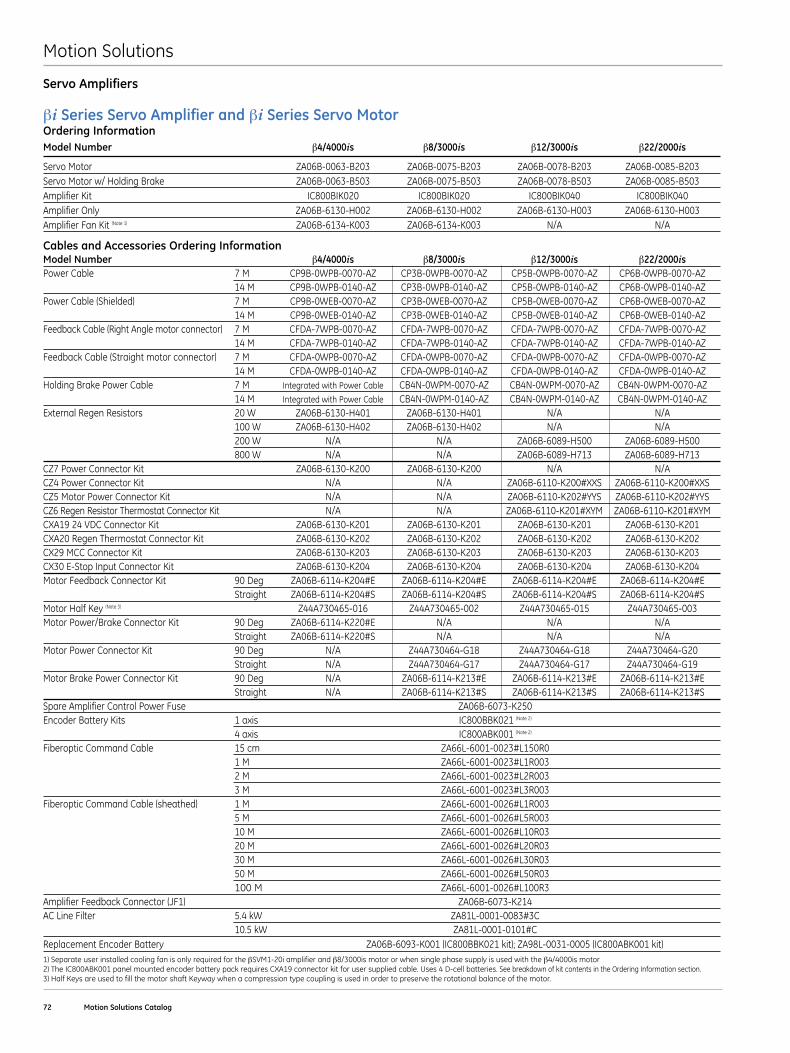
Motion Solutions
72 Motion Solutions Catalog
Servo Amplifiers
βi Series Servo Amplifier and βi Series Servo MotorOrdering InformationModel Number β4/4000is β8/3000is β12/3000is β22/2000is
Servo Motor ZA06B-0063-B203 ZA06B-0075-B203 ZA06B-0078-B203 ZA06B-0085-B203Servo Motor w/ Holding Brake ZA06B-0063-B503 ZA06B-0075-B503 ZA06B-0078-B503 ZA06B-0085-B503Amplifier Kit IC800BIK020 IC800BIK020 IC800BIK040 IC800BIK040Amplifier Only ZA06B-6130-H002 ZA06B-6130-H002 ZA06B-6130-H003 ZA06B-6130-H003Amplifier Fan Kit (Note 1) ZA06B-6134-K003 ZA06B-6134-K003 N/A N/A
Cables and Accessories Ordering InformationModel Number β4/4000is β8/3000is β12/3000is β22/2000isPower Cable 7 M CP9B-0WPB-0070-AZ CP3B-0WPB-0070-AZ CP5B-0WPB-0070-AZ CP6B-0WPB-0070-AZ 14 M CP9B-0WPB-0140-AZ CP3B-0WPB-0140-AZ CP5B-0WPB-0140-AZ CP6B-0WPB-0140-AZPower Cable (Shielded) 7 M CP9B-0WEB-0070-AZ CP3B-0WEB-0070-AZ CP5B-0WEB-0070-AZ CP6B-0WEB-0070-AZ 14 M CP9B-0WEB-0140-AZ CP3B-0WEB-0140-AZ CP5B-0WEB-0140-AZ CP6B-0WEB-0140-AZFeedback Cable (Right Angle motor connector) 7 M CFDA-7WPB-0070-AZ CFDA-7WPB-0070-AZ CFDA-7WPB-0070-AZ CFDA-7WPB-0070-AZ 14 M CFDA-7WPB-0140-AZ CFDA-7WPB-0140-AZ CFDA-7WPB-0140-AZ CFDA-7WPB-0140-AZFeedback Cable (Straight motor connector) 7 M CFDA-0WPB-0070-AZ CFDA-0WPB-0070-AZ CFDA-0WPB-0070-AZ CFDA-0WPB-0070-AZ 14 M CFDA-0WPB-0140-AZ CFDA-0WPB-0140-AZ CFDA-0WPB-0140-AZ CFDA-0WPB-0140-AZHolding Brake Power Cable 7 M Integrated with Power Cable CB4N-0WPM-0070-AZ CB4N-0WPM-0070-AZ CB4N-0WPM-0070-AZ 14 M Integrated with Power Cable CB4N-0WPM-0140-AZ CB4N-0WPM-0140-AZ CB4N-0WPM-0140-AZExternal Regen Resistors 20 W ZA06B-6130-H401 ZA06B-6130-H401 N/A N/A 100 W ZA06B-6130-H402 ZA06B-6130-H402 N/A N/A 200 W N/A N/A ZA06B-6089-H500 ZA06B-6089-H500 800 W N/A N/A ZA06B-6089-H713 ZA06B-6089-H713CZ7 Power Connector Kit ZA06B-6130-K200 ZA06B-6130-K200 N/A N/ACZ4 Power Connector Kit N/A N/A ZA06B-6110-K200#XXS ZA06B-6110-K200#XXSCZ5 Motor Power Connector Kit N/A N/A ZA06B-6110-K202#YYS ZA06B-6110-K202#YYSCZ6 Regen Resistor Thermostat Connector Kit N/A N/A ZA06B-6110-K201#XYM ZA06B-6110-K201#XYMCXA19 24 VDC Connector Kit ZA06B-6130-K201 ZA06B-6130-K201 ZA06B-6130-K201 ZA06B-6130-K201CXA20 Regen Thermostat Connector Kit ZA06B-6130-K202 ZA06B-6130-K202 ZA06B-6130-K202 ZA06B-6130-K202CX29 MCC Connector Kit ZA06B-6130-K203 ZA06B-6130-K203 ZA06B-6130-K203 ZA06B-6130-K203CX30 E-Stop Input Connector Kit ZA06B-6130-K204 ZA06B-6130-K204 ZA06B-6130-K204 ZA06B-6130-K204Motor Feedback Connector Kit 90 Deg ZA06B-6114-K204#E ZA06B-6114-K204#E ZA06B-6114-K204#E ZA06B-6114-K204#E Straight ZA06B-6114-K204#S ZA06B-6114-K204#S ZA06B-6114-K204#S ZA06B-6114-K204#SMotor Half Key (Note 3) Z44A730465-016 Z44A730465-002 Z44A730465-015 Z44A730465-003Motor Power/Brake Connector Kit 90 Deg ZA06B-6114-K220#E N/A N/A N/A Straight ZA06B-6114-K220#S N/A N/A N/AMotor Power Connector Kit 90 Deg N/A Z44A730464-G18 Z44A730464-G18 Z44A730464-G20 Straight N/A Z44A730464-G17 Z44A730464-G17 Z44A730464-G19Motor Brake Power Connector Kit 90 Deg N/A ZA06B-6114-K213#E ZA06B-6114-K213#E ZA06B-6114-K213#E Straight N/A ZA06B-6114-K213#S ZA06B-6114-K213#S ZA06B-6114-K213#SSpare Amplifier Control Power Fuse ZA06B-6073-K250Encoder Battery Kits 1 axis IC800BBK021 (Note 2)
4 axis IC800ABK001 (Note 2)
Fiberoptic Command Cable 15 cm ZA66L-6001-0023#L150R0 1 M ZA66L-6001-0023#L1R003 2 M ZA66L-6001-0023#L2R003 3 M ZA66L-6001-0023#L3R003Fiberoptic Command Cable (sheathed) 1 M ZA66L-6001-0026#L1R003 5 M ZA66L-6001-0026#L5R003 10 M ZA66L-6001-0026#L10R03 20 M ZA66L-6001-0026#L20R03 30 M ZA66L-6001-0026#L30R03 50 M ZA66L-6001-0026#L50R03 100 M ZA66L-6001-0026#L100R3Amplifier Feedback Connector (JF1) ZA06B-6073-K214AC Line Filter 5 .4 kW ZA81L-0001-0083#3C 10 .5 kW ZA81L-0001-0101#CReplacement Encoder Battery ZA06B-6093-K001 (IC800BBK021 kit); ZA98L-0031-0005 (IC800ABK001 kit)1) Separate user installed cooling fan is only required for the βSVM1-20i amplifier and β8/3000is motor or when single phase supply is used with the β4/4000is motor2) The IC800ABK001 panel mounted encoder battery pack requires CXA19 connector kit for user supplied cable . Uses 4 D-cell batteries . See breakdown of kit contents in the Ordering Information section .3) Half Keys are used to fill the motor shaft Keyway when a compression type coupling is used in order to preserve the rotational balance of the motor .
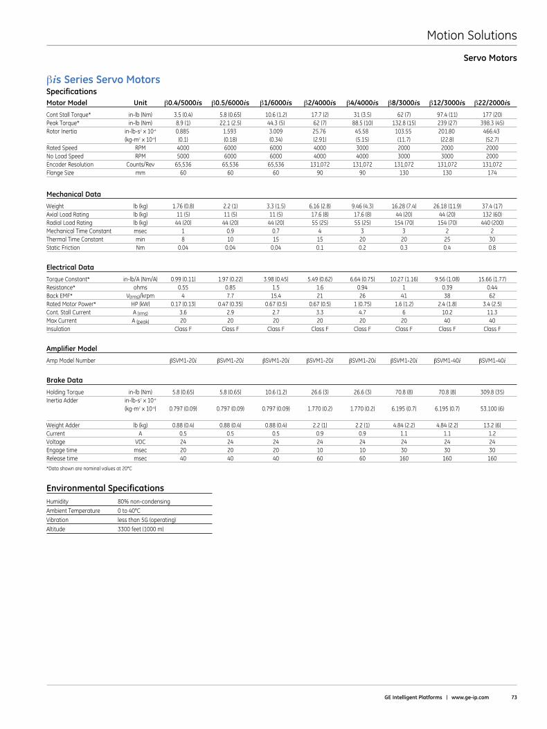
Motion Solutions
GE Intelligent Platforms | www .ge-ip .com 73
Servo Motors
βisSeries Servo MotorsSpecificationsMotor Model Unit β0 .4/5000is β0 .5/6000is β1/6000is β2/4000is β4/4000is β8/3000is β12/3000is β22/2000is
Cont Stall Torque* in-lb (Nm) 3 .5 (0 .4) 5 .8 (0 .65) 10 .6 (1 .2) 17 .7 (2) 31 (3 .5) 62 (7) 97 .4 (11) 177 (20)Peak Torque* in-lb (Nm) 8 .9 (1) 22 .1 (2 .5) 44 .3 (5) 62 (7) 88 .5 (10) 132 .8 (15) 239 (27) 398 .3 (45)Rotor Inertia in-lb-s2 x 10-4 0 .885 1 .593 3 .009 25 .76 45 .58 103 .55 201 .80 466 .43 (kg-m2 x 10-4) (0 .1) (0 .18) (0 .34) (2 .91) (5 .15) (11 .7) (22 .8) (52 .7) Rated Speed RPM 4000 6000 6000 4000 3000 2000 2000 2000No Load Speed RPM 5000 6000 6000 4000 4000 3000 3000 2000Encoder Resolution Counts/Rev 65,536 65,536 65,536 131,072 131,072 131,072 131,072 131,072Flange Size mm 60 60 60 90 90 130 130 174
Mechanical Data
Weight lb (kg) 1 .76 (0 .8) 2 .2 (1) 3 .3 (1 .5) 6 .16 (2 .8) 9 .46 (4 .3) 16 .28 (7 .4) 26 .18 (11 .9) 37 .4 (17)Axial Load Rating lb (kg) 11 (5) 11 (5) 11 (5) 17 .6 (8) 17 .6 (8) 44 (20) 44 (20) 132 (60)Radial Load Rating lb (kg) 44 (20) 44 (20) 44 (20) 55 (25) 55 (25) 154 (70) 154 (70) 440 (200)Mechanical Time Constant msec 1 0 .9 0 .7 4 3 3 2 2Thermal Time Constant min 8 10 15 15 20 20 25 30Static Friction Nm 0 .04 0 .04 0 .04 0 .1 0 .2 0 .3 0 .4 0 .8
Electrical Data
Torque Constant* in-lb/A (Nm/A) 0 .99 (0 .11) 1 .97 (0 .22) 3 .98 (0 .45) 5 .49 (0 .62) 6 .64 (0 .75) 10 .27 (1 .16) 9 .56 (1 .08) 15 .66 (1 .77)Resistance* ohms 0 .55 0 .85 1 .5 1 .6 0 .94 1 0 .39 0 .44Back EMF* V(rms)/krpm 4 7 .7 15 .4 21 26 41 38 62Rated Motor Power* HP (kW) 0 .17 (0 .13) 0 .47 (0 .35) 0 .67 (0 .5) 0 .67 (0 .5) 1 (0 .75) 1 .6 (1 .2) 2 .4 (1 .8) 3 .4 (2 .5)Cont . Stall Current A (rms) 3 .6 2 .9 2 .7 3 .3 4 .7 6 10 .2 11 .3Max Current A (peak) 20 20 20 20 20 20 40 40Insulation Class F Class F Class F Class F Class F Class F Class F Class F
Amplifier Model
Amp Model Number βSVM1-20i βSVM1-20i βSVM1-20i βSVM1-20i βSVM1-20i βSVM1-20i βSVM1-40i βSVM1-40i
Brake Data
Holding Torque in-lb (Nm) 5 .8 (0 .65) 5 .8 (0 .65) 10 .6 (1 .2) 26 .6 (3) 26 .6 (3) 70 .8 (8) 70 .8 (8) 309 .8 (35)Inertia Adder in-lb-s2 x 10-4 (kg-m2 x 10-4) 0 .797 (0 .09) 0 .797 (0 .09) 0 .797 (0 .09) 1 .770 (0 .2) 1 .770 (0 .2) 6 .195 (0 .7) 6 .195 (0 .7) 53 .100 (6) Weight Adder lb (kg) 0 .88 (0 .4) 0 .88 (0 .4) 0 .88 (0 .4) 2 .2 (1) 2 .2 (1) 4 .84 (2 .2) 4 .84 (2 .2) 13 .2 (6)Current A 0 .5 0 .5 0 .5 0 .9 0 .9 1 .1 1 .1 1 .2Voltage VDC 24 24 24 24 24 24 24 24Engage time msec 20 20 20 10 10 30 30 30Release time msec 40 40 40 60 60 160 160 160
*Data shown are nominal values at 20°C
Environmental SpecificationsHumidity 80%non-condensingAmbient Temperature 0 to 40°CVibration less than 5G (operating)Altitude 3300 feet (1000 m)
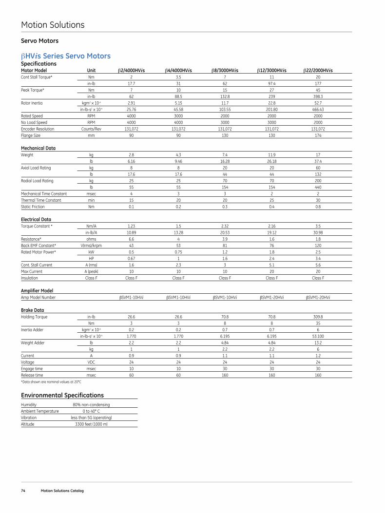
Motion Solutions
74 Motion Solutions Catalog
Servo Motors
βHVisSeries Servo MotorsSpecificationsMotor Model Unit β2/4000HVis β4/4000HVis β8/3000HVis β12/3000HVis β22/2000HVisCont Stall Torque* Nm 2 3 .5 7 11 20 in-lb 17 .7 31 62 97 .4 177Peak Torque* Nm 7 10 15 27 45 in-lb 62 88 .5 132 .8 239 398 .3Rotor Inertia kgm2 x 10-4 2 .91 5 .15 11 .7 22 .8 52 .7 in-lb-s2 x 10-4 25 .76 45 .58 103 .55 201 .80 466 .43Rated Speed RPM 4000 3000 2000 2000 2000No Load Speed RPM 4000 4000 3000 3000 2000Encoder Resolution Counts/Rev 131,072 131,072 131,072 131,072 131,072Flange Size mm 90 90 130 130 174
Mechanical DataWeight kg 2 .8 4 .3 7 .4 11 .9 17 lb 6 .16 9 .46 16 .28 26 .18 37 .4Axial Load Rating kg 8 8 20 20 60 lb 17 .6 17 .6 44 44 132Radial Load Rating kg 25 25 70 70 200 lb 55 55 154 154 440Mechanical Time Constant msec 4 3 3 2 2Thermal Time Constant min 15 20 20 25 30Static Friction Nm 0 .1 0 .2 0 .3 0 .4 0 .8
Electrical DataTorque Constant * Nm/A 1 .23 1 .5 2 .32 2 .16 3 .5 in-lb/A 10 .89 13 .28 20 .53 19 .12 30 .98Resistance* ohms 6 .6 4 3 .9 1 .6 1 .8Back EMF Constant* V(rms)/krpm 43 53 81 76 120Rated Motor Power* kW 0 .5 0 .75 1 .2 1 .8 2 .5 HP 0 .67 1 1 .6 2 .4 3 .4Cont . Stall Current A (rms) 1 .6 2 .3 3 5 .1 5 .6Max Current A (peak) 10 10 10 20 20Insulation Class F Class F Class F Class F Class F Class F
Amplifier ModelAmp Model Number βSVM1-10HVi βSVM1-10HVi βSVM1-10HVi βSVM1-20HVi βSVM1-20HVi
Brake DataHolding Torque in-lb 26 .6 26 .6 70 .8 70 .8 309 .8 Nm 3 3 8 8 35Inertia Adder kgm2 x 10-4 0 .2 0 .2 0 .7 0 .7 6 in-lb-s2 x 10-4 1 .770 1 .770 6 .195 6 .195 53 .100Weight Adder lb 2 .2 2 .2 4 .84 4 .84 13 .2 kg 1 1 2 .2 2 .2 6Current A 0 .9 0 .9 1 .1 1 .1 1 .2Voltage VDC 24 24 24 24 24Engage time msec 10 10 30 30 30Release time msec 60 60 160 160 160*Data shown are nominal values at 20°C
Environmental SpecificationsHumidity 80%non-condensingAmbient Temperature 0 to 40° CVibration less than 5G (operating)Altitude 3300 feet (1000 m)
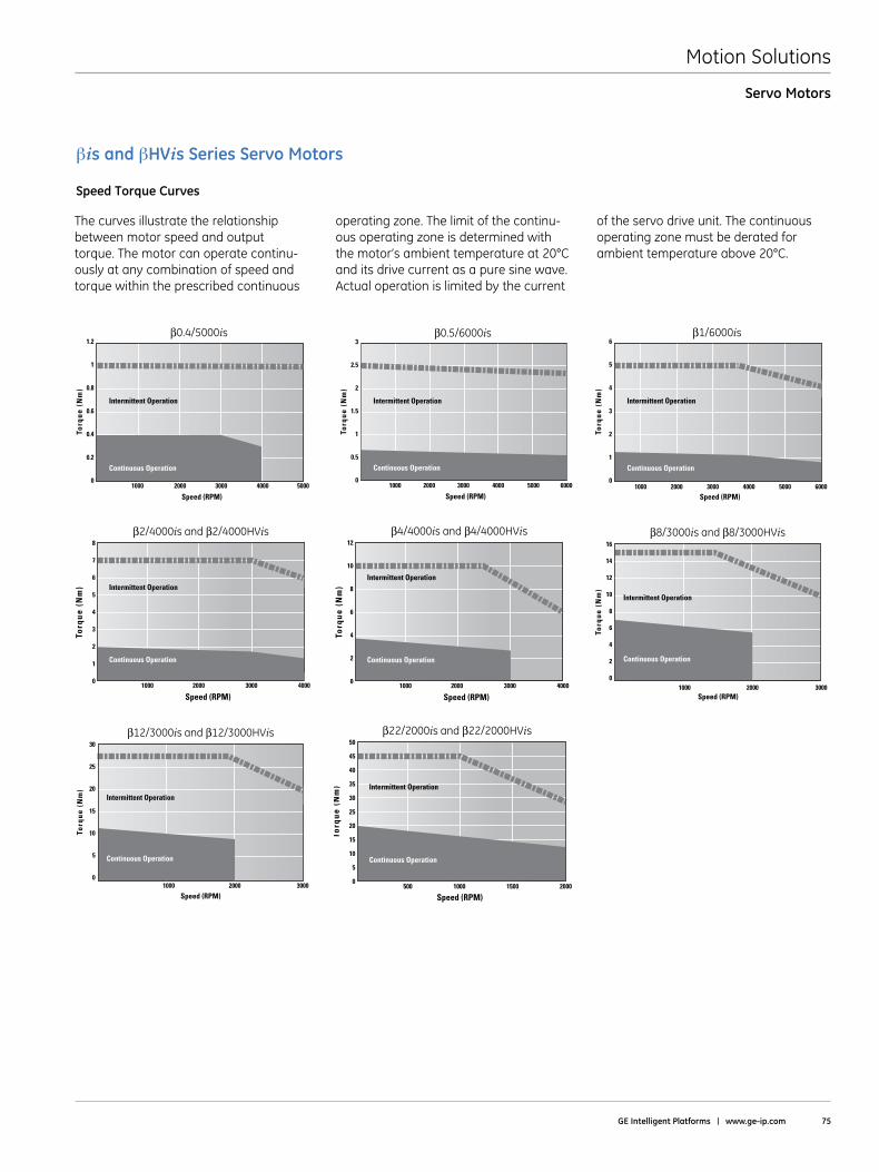
Motion Solutions
GE Intelligent Platforms | www .ge-ip .com 75
Servo Motors
10000
15
20
25
10
5
30
2000 3000
Torq
ue (
Nm
)
β12/3000is and β12/3000HVis
Speed (RPM)
Intermittent Operation
Continuous Operation
Torq
ue (
Nm
)
β22/2000is and β22/2000HVis
Speed (RPM)
0
5
10
20
30
25
40
35
45
15
50
15001000500
Intermittent Operation
2000
Continuous Operation
4000 6000500010000
3
2.5
2
1.5
1
0.5
2000 3000
Torq
ue (
Nm
)β0.5/6000is
Speed (RPM)
Intermittent Operation
Continuous Operation
4000 5000 600010000
6
5
4
3
2
1
2000 3000
Torq
ue (
Nm
)
β1/6000is
Speed (RPM)
Intermittent Operation
Continuous Operation
4000 500010000
1.2
1
0.8
0.6
0.4
0.2
2000 3000
Torq
ue (
Nm
)
β0.4/5000is
Speed (RPM)
Intermittent Operation
Continuous Operation
10000
6
8
10
4
2
12
14
16
2000 3000
Torq
ue (
Nm
)
β8/3000is and β8/3000HVis
Speed (RPM)
Intermittent Operation
Continuous Operation
Torq
ue (
Nm
)
β2/4000is and β2/4000HVis
Speed (RPM)
0
1
2
4
6
5
7
3
8
300020001000
Intermittent Operation
Continuous Operation
4000
Torq
ue (
Nm
)
β4/4000is and β4/4000HVis
Speed (RPM)
0
2
4
8
10
6
12
300020001000
Intermittent Operation
Continuous Operation
4000
The curves illustrate the relationship between motor speed and output torque . The motor can operate continu-ously at any combination of speed and torque within the prescribed continuous
operating zone . The limit of the continu-ous operating zone is determined with the motor’s ambient temperature at 20°C and its drive current as a pure sine wave . Actual operation is limited by the current
of the servo drive unit . The continuous operating zone must be derated for ambient temperature above 20°C .
βis and βHVis Series Servo Motors
Speed Torque Curves
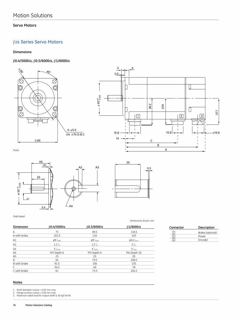
Motion Solutions
76 Motion Solutions Catalog
Servo Motors
(3)
3.5
20
A4
A5
A2 A3
20
0.5
A1
ø 5
0-0
.025
+0
B04/4_05/5_1/5iseries_SHAFT.eps
βis Series Servo Motors
Dimensions
β0 .4/5000is, β0 .5/6000is, β1/6000is
16.8
63
0.5
38.2
37.6
37.7
15.8 15.8
14C
B
A
ø 5
0-0
.025
+0
ø
1 2 3
B04/5_05/5_1/5iseries_MOTOR.eps
45º
ø 80
60
4- ø5.5
ON ø70 D.B.C
Connector Description
1 Brake (optional) 2 Power 3 Encoder
Shaft detail
Motor
Dimensions shown mm
Dimension β0 .4/5000is β0 .5/6000is β1/6000is
A 75 89 .5 118 .5A with brake 101 .5 116 145
A1 ø9 0-0 .009 ø9 0
-0 .009 ø14 0-0 .011
A2 1 .2 0-0 .1 1 .2 0
-0 .1 2 0-0 .1
A3 3 0-0 .025 3 0
-0 .025 5 0-0 .33
A4 M3 Depth 6 M3 Depth 6 M4 Depth 10A5 25 25 30B 65 79 .5 108 .5B with brake 91 .5 106 135C 34 .5 49 78C with brake 61 75 .5 104 .5
Notes
1 . Shaft diameter runout = 0 .02 mm max2 . Flange surface runout = 0 .06 mm max3 . Maximum radial load for output shaft is 20 kgf (44 lb)
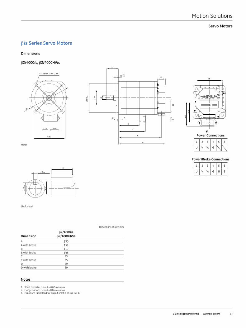
Motion Solutions
GE Intelligent Platforms | www .ge-ip .com 77
Servo Motors
βis Series Servo Motors
Dimensions
β2/4000is, β2/4000HVis
B2/4_4/4iseries_SHAFT.eps
11.2
10
3
18
-0.025+0
-0.0
09+0
5
M5 Depth 12
16
11
-0.030+0
14
23
128
+0.0
01+0
.012
ø90
21.4 30.6
B2/4_iseries_MOTOR.eps
ø120
4- ø6.6 ON ø100 D.B.C
73
10
32
12
D
C
B
A
4
22
40
8.7
ø 8
0 ø 4
3
-0.0
3+0
-0.5+0.5
66.2
56.7
75
Shaft detail
Motor
Dimensions shown mm
β2/4000is Dimension β2/4000HVis
A 130A with brake 159B 119B with brake 148C 75C with brake 75D 59D with brake 59
Notes
1 . Shaft diameter runout = 0 .02 mm max2 . Flange surface runout = 0 .06 mm max3 . Maximum radial load for output shaft is 25 kgf (55 lb)
1 2 3 4 5
U V W G
6
Power Connections
1 2 3 4 5
U V W G B B
6
Power/Brake Connections
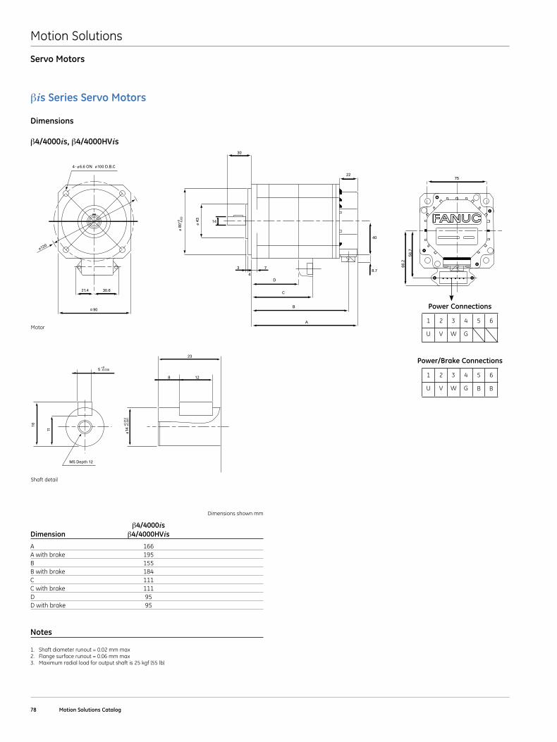
Motion Solutions
78 Motion Solutions Catalog
Servo Motors
βis Series Servo Motors
Dimensions
β4/4000is, β4/4000HVis
B2/4_4/4iseries_SHAFT.eps
11.2
10
3
18
-0.025+0
-0.0
09+0
5
M5 Depth 12
16
11
-0.030+0
14
23
128
+0.0
01+0
.012
ø
90
21.4 30.6
B4/4_iseries_MOTOR.eps
ø120
4- ø6.6 ON ø100 D.B.C
7
30
D
C
B
A
22
40
8.7
ø 8
0 ø 4
3
-0.0
3+0
3
4
14
66.2
56.7
75
Shaft detail
Motor
Dimensions shown mm
β4/4000is Dimension β4/4000HVis
A 166A with brake 195B 155B with brake 184C 111C with brake 111D 95D with brake 95
Notes
1 . Shaft diameter runout = 0 .02 mm max2 . Flange surface runout = 0 .06 mm max3 . Maximum radial load for output shaft is 25 kgf (55 lb)
1 2 3 4 5
U V W G
6
Power Connections
1 2 3 4 5
U V W G B B
6
Power/Brake Connections
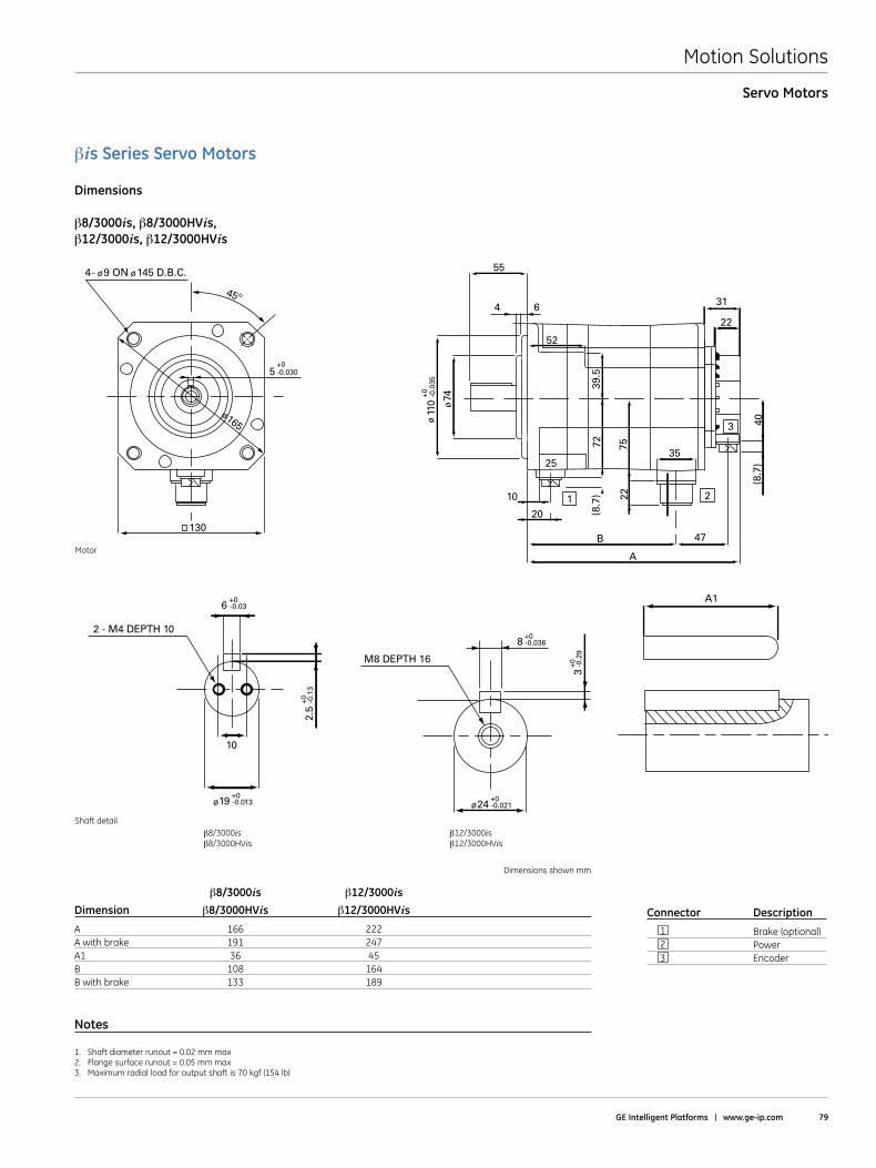
Motion Solutions
GE Intelligent Platforms | www .ge-ip .com 79
Servo Motors
B8/3_12/3iseries_SHAFT.eps
8
M8 DEPTH 16
24
A1
-0.036+0
3-0
.29
+0
-0.021+0
ø
2.5
10
2 - M4 DEPTH 10
-0.1
3+0
19 -0.013+0
6 -0.03+0
ø
B8/3_12/3iseries_MOTOR.eps
1
B
20
10
A
2
47
3
31
52
6
55
4
40
3525
75
(8.7
)
(8.7
)
22
39.5
72
74
110
22
ø
ø-0
.035
+0
45º
130
5
4- ø9 ON ø145 D.B.C.
ø165
-0.030+0
Connector Description
1 Brake (optional) 2 Power 3 Encoder
Shaft detail
Motor
βis Series Servo Motors
Dimensions
β8/3000is, β8/3000HVis, β12/3000is, β12/3000HVis
Dimensions shown mm
β8/3000is β12/3000is Dimension β8/3000HVis β12/3000HVis
A 166 222A with brake 191 247A1 36 45
B 108 164B with brake 133 189
Notes
1 . Shaft diameter runout = 0 .02 mm max2 . Flange surface runout = 0 .05 mm max3 . Maximum radial load for output shaft is 70 kgf (154 lb)
β8/3000isβ8/3000HVis
β12/3000isβ12/3000HVis
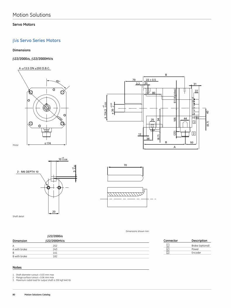
Motion Solutions
80 Motion Solutions Catalog
Servo Motors
B22/2iseries_SHAFT.eps
70
32 - M6 DEPTH 10
-0.3
0+0
20
10 -0.038+0
1
B
B
12
38
25
A
2
50
44
22
31
80
3.279
2022 ± 0.5
40(8
.7)
(8.7
) (22)
105
94
51 (
4 si
des
)
114.
3 35
3
ø
ø-0
.025
+0 -0+0.0
1
B22/2iseries_MOTOR.eps
45º
174
4- ø13.5 ON ø200 D.B.C.
ø230
Connector Description
1 Brake (optional) 2 Power 3 Encoder
Shaft detail
Motor
βis Servo Series Motors
Dimensions
β22/2000is, β22/2000HVis
Dimensions shown mm
β22/2000isDimension β22/2000HVis
A 202A with brake 243B 141B with brake 182
Notes
1 . Shaft diameter runout = 0 .03 mm max2 . Flange surface runout = 0 .06 mm max3 . Maximum radial load for output shaft is 200 kgf (440 lb)
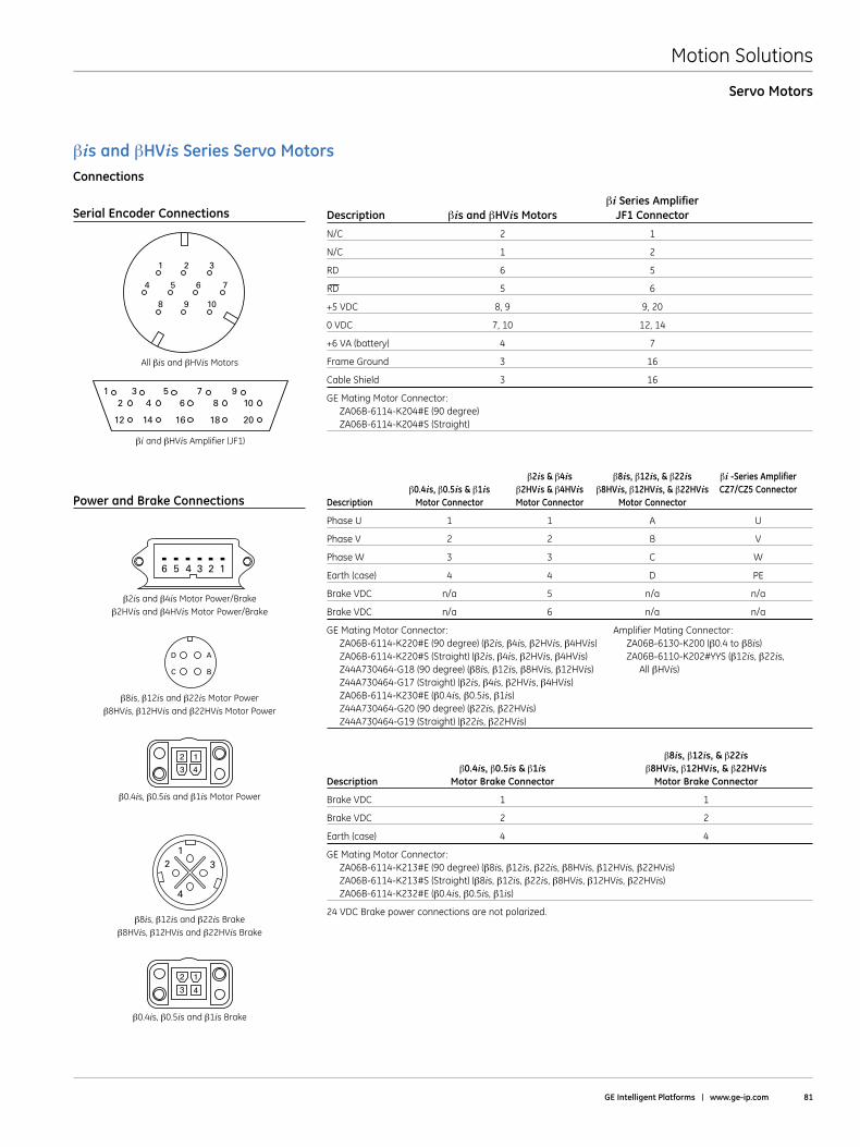
Motion Solutions
GE Intelligent Platforms | www .ge-ip .com 81
Servo Motors
βi Series Amplifier Description βis and βHVis Motors JF1 Connector
N/C 2 1
N/C 1 2
RD 6 5
RD 5 6
+5 VDC 8, 9 9, 20
0 VDC 7, 10 12, 14
+6 VA (battery) 4 7
Frame Ground 3 16
Cable Shield 3 16
GE Mating Motor Connector: ZA06B-6114-K204#E (90 degree) ZA06B-6114-K204#S (Straight)
β2is & β4is β8is, β12is, & β22is βi -Series Amplifier β0 .4is, β0 .5is & β1is β2HVis & β4HVis β8HVis, β12HVis, & β22HVis CZ7/CZ5 Connector Description Motor Connector Motor Connector Motor Connector
Phase U 1 1 A U
Phase V 2 2 B V
Phase W 3 3 C W
Earth (case) 4 4 D PE
Brake VDC n/a 5 n/a n/a
Brake VDC n/a 6 n/a n/a
GE Mating Motor Connector: Amplifier Mating Connector: ZA06B-6114-K220#E (90 degree) (β2is, β4is, β2HVis, β4HVis) ZA06B-6130-K200 (β0 .4 to β8is) ZA06B-6114-K220#S (Straight) (β2is, β4is, β2HVis, β4HVis) ZA06B-6110-K202#YYS (β12is, β22is, Z44A730464-G18 (90 degree) (β8is, β12is, β8HVis, β12HVis) All βHVis) Z44A730464-G17 (Straight) (β2is, β4is, β2HVis, β4HVis) ZA06B-6114-K230#E (β0 .4is, β0 .5is, β1is) Z44A730464-G20 (90 degree) (β22is, β22HVis) Z44A730464-G19 (Straight) (β22is, β22HVis)
β8is, β12is, & β22is β0 .4is, β0 .5is & β1is β8HVis, β12HVis, & β22HVis Description Motor Brake Connector Motor Brake Connector
Brake VDC 1 1
Brake VDC 2 2
Earth (case) 4 4
GE Mating Motor Connector: ZA06B-6114-K213#E (90 degree) (β8is, β12is, β22is, β8HVis, β12HVis, β22HVis) ZA06B-6114-K213#S (Straight) (β8is, β12is, β22is, β8HVis, β12HVis, β22HVis) ZA06B-6114-K232#E (β0 .4is, β0 .5is, β1is)
24 VDC Brake power connections are not polarized .
All βis and βHVis Motors
Connections
Serial Encoder Connections
1 2 3
8 9 10
4 5 6 7
132
4
23
14
β8is, β12is and β22is Motor Powerβ8HVis, β12HVis and β22HVis Motor Power
β0 .4is, β0 .5is and β1is Motor Power
β8is, β12is and β22is Brakeβ8HVis, β12HVis and β22HVis Brake
β0 .4is, β0 .5is and β1is Brake
Power and Brake Connections
A
BC
D
23
14
6 5 4 3 2 1
β2is and β4is Motor Power/Brakeβ2HVis and β4HVis Motor Power/Brake
βiand βHVis Amplifier (JF1)
3 5 7 94 6 8 10
14 16 18 20
12
12
βis and βHVis Series Servo Motors
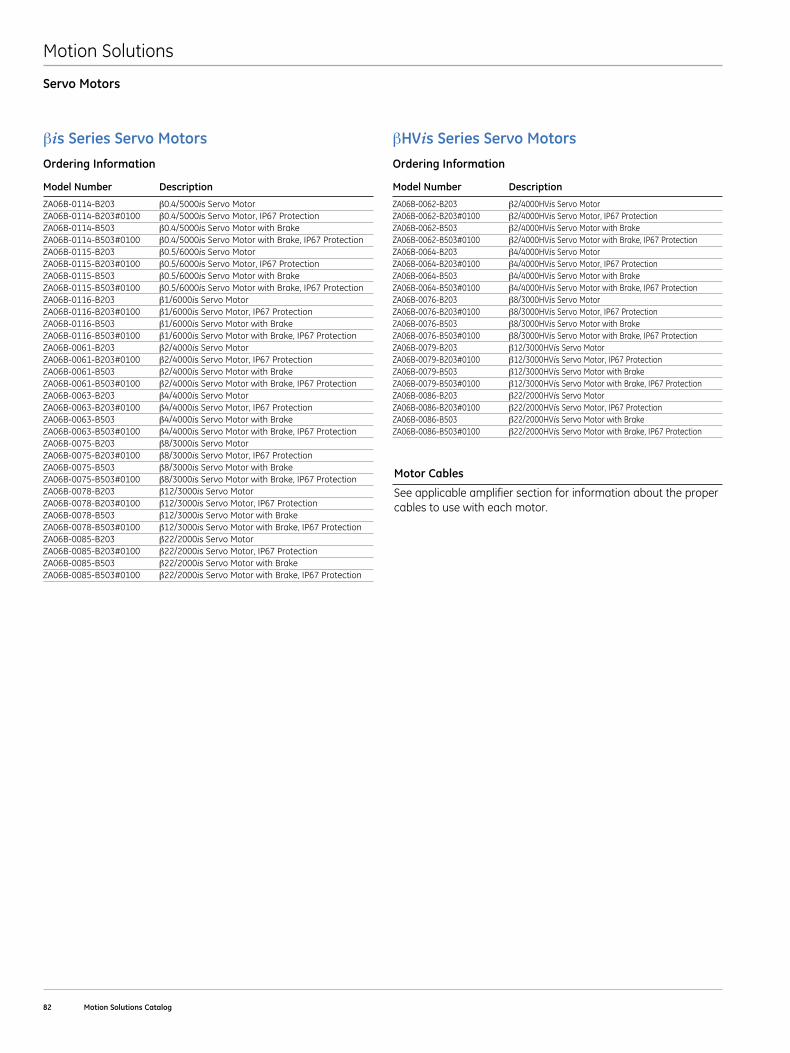
Motion Solutions
82 Motion Solutions Catalog
Servo Motors
βis Series Servo Motors Ordering Information
Model Number Description
ZA06B-0114-B203 β0 .4/5000is Servo MotorZA06B-0114-B203#0100 β0 .4/5000is Servo Motor, IP67 ProtectionZA06B-0114-B503 β0 .4/5000is Servo Motor with Brake ZA06B-0114-B503#0100 β0 .4/5000is Servo Motor with Brake, IP67 ProtectionZA06B-0115-B203 β0 .5/6000is Servo MotorZA06B-0115-B203#0100 β0 .5/6000is Servo Motor, IP67 ProtectionZA06B-0115-B503 β0 .5/6000is Servo Motor with BrakeZA06B-0115-B503#0100 β0 .5/6000is Servo Motor with Brake, IP67 ProtectionZA06B-0116-B203 β1/6000is Servo MotorZA06B-0116-B203#0100 β1/6000is Servo Motor, IP67 ProtectionZA06B-0116-B503 β1/6000is Servo Motor with BrakeZA06B-0116-B503#0100 β1/6000is Servo Motor with Brake, IP67 ProtectionZA06B-0061-B203 β2/4000is Servo MotorZA06B-0061-B203#0100 β2/4000is Servo Motor, IP67 ProtectionZA06B-0061-B503 β2/4000is Servo Motor with BrakeZA06B-0061-B503#0100 β2/4000is Servo Motor with Brake, IP67 ProtectionZA06B-0063-B203 β4/4000is Servo MotorZA06B-0063-B203#0100 β4/4000is Servo Motor, IP67 ProtectionZA06B-0063-B503 β4/4000is Servo Motor with BrakeZA06B-0063-B503#0100 β4/4000is Servo Motor with Brake, IP67 ProtectionZA06B-0075-B203 β8/3000is Servo MotorZA06B-0075-B203#0100 β8/3000is Servo Motor, IP67 ProtectionZA06B-0075-B503 β8/3000is Servo Motor with BrakeZA06B-0075-B503#0100 β8/3000is Servo Motor with Brake, IP67 ProtectionZA06B-0078-B203 β12/3000is Servo MotorZA06B-0078-B203#0100 β12/3000is Servo Motor, IP67 ProtectionZA06B-0078-B503 β12/3000is Servo Motor with BrakeZA06B-0078-B503#0100 β12/3000is Servo Motor with Brake, IP67 ProtectionZA06B-0085-B203 β22/2000is Servo MotorZA06B-0085-B203#0100 β22/2000is Servo Motor, IP67 ProtectionZA06B-0085-B503 β22/2000is Servo Motor with BrakeZA06B-0085-B503#0100 β22/2000is Servo Motor with Brake, IP67 Protection
βHVis Series Servo MotorsOrdering Information
Model Number Description
ZA06B-0062-B203 β2/4000HVis Servo MotorZA06B-0062-B203#0100 β2/4000HVis Servo Motor, IP67 ProtectionZA06B-0062-B503 β2/4000HVis Servo Motor with BrakeZA06B-0062-B503#0100 β2/4000HVis Servo Motor with Brake, IP67 ProtectionZA06B-0064-B203 β4/4000HVis Servo MotorZA06B-0064-B203#0100 β4/4000HVis Servo Motor, IP67 ProtectionZA06B-0064-B503 β4/4000HVis Servo Motor with BrakeZA06B-0064-B503#0100 β4/4000HVis Servo Motor with Brake, IP67 ProtectionZA06B-0076-B203 β8/3000HVis Servo MotorZA06B-0076-B203#0100 β8/3000HVis Servo Motor, IP67 ProtectionZA06B-0076-B503 β8/3000HVis Servo Motor with BrakeZA06B-0076-B503#0100 β8/3000HVis Servo Motor with Brake, IP67 ProtectionZA06B-0079-B203 β12/3000HVis Servo MotorZA06B-0079-B203#0100 β12/3000HVis Servo Motor, IP67 ProtectionZA06B-0079-B503 β12/3000HVis Servo Motor with BrakeZA06B-0079-B503#0100 β12/3000HVis Servo Motor with Brake, IP67 ProtectionZA06B-0086-B203 β22/2000HVis Servo MotorZA06B-0086-B203#0100 β22/2000HVis Servo Motor, IP67 ProtectionZA06B-0086-B503 β22/2000HVis Servo Motor with BrakeZA06B-0086-B503#0100 β22/2000HVis Servo Motor with Brake, IP67 Protection
Motor Cables
See applicable amplifier section for information about the proper cables to use with each motor .
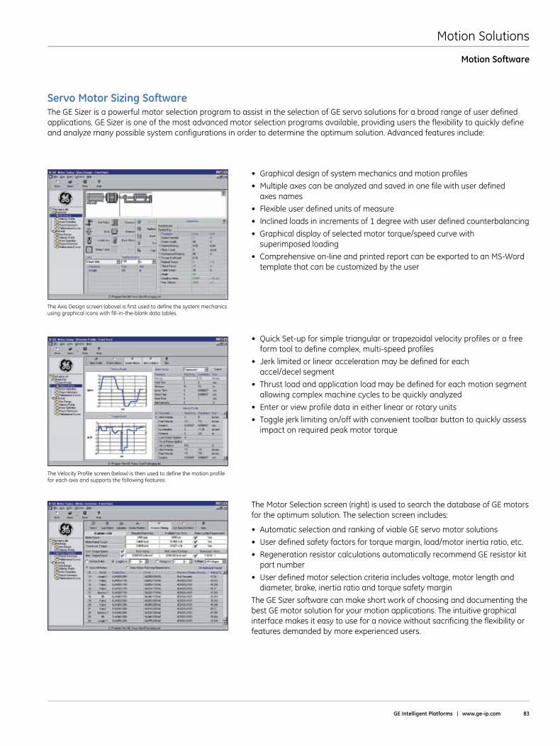
Motion Solutions
GE Intelligent Platforms | www .ge-ip .com 83
Motion Software
The GE Sizer is a powerful motor selection program to assist in the selection of GE servo solutions for a broad range of user defined applications . GE Sizer is one of the most advanced motor selection programs available, providing users the flexibility to quickly define and analyze many possible system configurations in order to determine the optimum solution . Advanced features include:
Servo Motor Sizing Software
• Graphicaldesignofsystemmechanicsandmotionprofiles
• Multipleaxescanbeanalyzedandsavedinonefilewithuserdefined axes names
• Flexibleuserdefinedunitsofmeasure
• Inclinedloadsinincrementsof1degreewithuserdefinedcounterbalancing
• Graphicaldisplayofselectedmotortorque/speedcurvewith superimposed loading
• Comprehensiveon-lineandprintedreportcanbeexportedtoanMS-Wordtemplate that can be customized by the user
The Axis Design screen (above) is first used to define the system mechanics using graphical icons with fill-in-the-blank data tables .
The Velocity Profile screen (below) is then used to define the motion profile for each axis and supports the following features:
• QuickSet-upforsimpletriangularortrapezoidalvelocityprofilesorafreeform tool to define complex, multi-speed profiles
• Jerklimitedorlinearaccelerationmaybedefinedforeach accel/decel segment
• Thrustloadandapplicationloadmaybedefinedforeachmotionsegmentallowing complex machine cycles to be quickly analyzed
• Enterorviewprofiledataineitherlinearorrotaryunits
• Togglejerklimitingon/offwithconvenienttoolbarbuttontoquicklyassessimpact on required peak motor torque
The Motor Selection screen (right) is used to search the database of GE motors for the optimum solution . The selection screen includes:
• AutomaticselectionandrankingofviableGEservomotorsolutions
• Userdefinedsafetyfactorsfortorquemargin,load/motorinertiaratio,etc.
• RegenerationresistorcalculationsautomaticallyrecommendGEresistorkitpart number
• Userdefinedmotorselectioncriteriaincludesvoltage,motorlengthanddiameter, brake, inertia ratio and torque safety margin
The GE Sizer software can make short work of choosing and documenting the best GE motor solution for your motion applications . The intuitive graphical interface makes it easy to use for a novice without sacrificing the flexibility or features demanded by more experienced users .

Motion Solutions
84 Motion Solutions Catalog
Index
Product Number Product Name Page Number Product Number Product Name Page Number
CB4N-0WPM-0070-AZ Holding Brake Power Cable, 7 M . . . . . . . . . . . . . . . . . . . . . . 46-49, 70, 72
CB4N-0WPM-0140-AZ Holding Brake Power Cable, 14 M . . . . . . . . . . . . . . . . . . . . . 46-49, 70, 72
CB5N-0WPM-0070-AZ Fan Cable, 7 M . . . . . . . . . . . . . . . . . . . . . . . . . . . . . . . . . . . . . . . . . . . . . . . . . . 49
CB5N-0WPM-0140-AZ Fan Cable, 14 M . . . . . . . . . . . . . . . . . . . . . . . . . . . . . . . . . . . . . . . . . . . . . . . . . 49
CB6N-5WPM-0070-AZ Holding Brake Power Cable, 7 M . . . . . . . . . . . . . . . . . . . . . . . . . . . . . . . . . 71
CB6N-5WPM-0140-AZ Holding Brake Power Cable, 14 M . . . . . . . . . . . . . . . . . . . . . . . . . . . . . . . . 71
CFDA-0WPB-0070-AZ Feedback Cable (Straight motor connector), 7 M . . . . . . . . 46-49, 70-72
CFDA-0WPB-0140-AZ Feedback Cable (Straight motor connector), 14 M . . . . . . . . 46-49, 70-72
CFDA-7WPB-0070-AZ Feedback Cable (Right Angle motor connector), 7 M . . . . 46-49, 70-72
CFDA-7WPB-0140-AZ Feedback Cable (Right Angle motor connector), 14 M . . . 46-49, 70-72
CP2I-0WEB-0070-AZ Power Cable (Shielded), 7 M . . . . . . . . . . . . . . . . . . . . . . . . . . . . . . . . . 46, 70
CP2I-0WEB-0140-AZ Power Cable (Shielded), 14 M . . . . . . . . . . . . . . . . . . . . . . . . . . . . . . . . 46, 70
CP2I-0WPB-0070-AZ Power Cable, 7 M . . . . . . . . . . . . . . . . . . . . . . . . . . . . . . . . . . . . . . . . . . . 46, 70
CP2I-0WPB-0140-AZ Power Cable, 14 M . . . . . . . . . . . . . . . . . . . . . . . . . . . . . . . . . . . . . . . . . . 46, 70
CP3B-0WEB-0070-AZ Power Cable (Shielded), 7 M . . . . . . . . . . . . . . . . . . . . . . . . . . . . . . . . . . . . . 72
CP3B-0WEB-0140-AZ Power Cable (Shielded), 14 M . . . . . . . . . . . . . . . . . . . . . . . . . . . . . . . . . . . . 72
CP3B-0WPB-0070-AZ Power Cable, 7 M . . . . . . . . . . . . . . . . . . . . . . . . . . . . . . . . . . . . . . . . . . . . . . . 72
CP3B-0WPB-0140-AZ Power Cable, 14 M . . . . . . . . . . . . . . . . . . . . . . . . . . . . . . . . . . . . . . . . . . . . . . 72
CP2I-0WEB-0070-AZ Power Cable (Shielded), 7 M . . . . . . . . . . . . . . . . . . . . . . . . . . . . . . . . . 46, 70
CP2I-0WEB-0140-AZ Power Cable (Shielded), 14 M . . . . . . . . . . . . . . . . . . . . . . . . . . . . . . . . 46, 70
CP2I-0WPB-0070-AZ Power Cable, 7 M . . . . . . . . . . . . . . . . . . . . . . . . . . . . . . . . . . . . . . . . . . . 46, 70
CP2I-0WPB-0140-AZ Power Cable, 14 M . . . . . . . . . . . . . . . . . . . . . . . . . . . . . . . . . . . . . . . . . . 46, 70
CP3I-0WEB-0070-AZ Power Cable (Shielded), 7 M . . . . . . . . . . . . . . . . . . . . . . . . . . . . . . 46, 47, 70
CP3I-0WEB-0140-AZ Power Cable (Shielded), 14 M . . . . . . . . . . . . . . . . . . . . . . . . . . . . . 46, 47, 70
CP3I-0WPB-0070-AZ Power Cable, 7 M . . . . . . . . . . . . . . . . . . . . . . . . . . . . . . . . . . . . . . . . 46, 47, 70
CP3I-0WPB-0140-AZ Power Cable, 14 M . . . . . . . . . . . . . . . . . . . . . . . . . . . . . . . . . . . . . . . 46, 47, 70
CP4I-0WEB-0070-AZ Power Cable (Shielded), 7 M . . . . . . . . . . . . . . . . . . . . . . . . . . . . . . 47, 48, 70
CP4I-0WEB-0140-AZ Power Cable (Shielded), 14 M . . . . . . . . . . . . . . . . . . . . . . . . . . . . . 47, 48, 70
CP4I-0WPB-0070-AZ Power Cable, 7 M . . . . . . . . . . . . . . . . . . . . . . . . . . . . . . . . . . . . . . . . 47, 48, 70
CP4I-0WPB-0140-AZ Power Cable, 14 M . . . . . . . . . . . . . . . . . . . . . . . . . . . . . . . . . . . . . . . 47, 48, 70
CP5B-0WEB-0070-AZ Power Cable (Shielded), 7 M . . . . . . . . . . . . . . . . . . . . . . . . . . . . . . . . . . . . . 72
CP5B-0WEB-0140-AZ Power Cable (Shielded), 14 M . . . . . . . . . . . . . . . . . . . . . . . . . . . . . . . . . . . . 72
CP5B-0WPB-0070-AZ Power Cable, 7 M . . . . . . . . . . . . . . . . . . . . . . . . . . . . . . . . . . . . . . . . . . . . . . . 72
CP5B-0WPB-0140-AZ Power Cable, 14 M . . . . . . . . . . . . . . . . . . . . . . . . . . . . . . . . . . . . . . . . . . . . . . 72
CP6B-0WEB-0070-AZ Power Cable (Shielded), 7 M . . . . . . . . . . . . . . . . . . . . . . . . . . . . . . . . . . . . . 72
CP6B-0WEB-0140-AZ Power Cable (Shielded), 14 M . . . . . . . . . . . . . . . . . . . . . . . . . . . . . . . . . . . . 72
CP6B-0WPB-0070-AZ Power Cable, 7 M . . . . . . . . . . . . . . . . . . . . . . . . . . . . . . . . . . . . . . . . . . . . . . . 72
CP6B-0WPB-0140-AZ Power Cable, 14 M . . . . . . . . . . . . . . . . . . . . . . . . . . . . . . . . . . . . . . . . . . . . . . 72
CP8B-1WEB-0070-AZ Power Cable (Shielded), 7 M . . . . . . . . . . . . . . . . . . . . . . . . . . . . . . . . . . . . . 71
CP8B-1WEB-0140-AZ Power Cable (Shielded), 14 M . . . . . . . . . . . . . . . . . . . . . . . . . . . . . . . . . . . . 71
CP8B-1WPB-0070-AZ Power Cable, 7 M . . . . . . . . . . . . . . . . . . . . . . . . . . . . . . . . . . . . . . . . . . . . . . . 71
CP8B-1WPB-0140-AZ Power Cable, 14 M . . . . . . . . . . . . . . . . . . . . . . . . . . . . . . . . . . . . . . . . . . . . . . 71
CP9B-0WEB-0070-AZ Power Cable (Shielded), 7 M . . . . . . . . . . . . . . . . . . . . . . . . . . . . . . . . . 71, 72
CP9B-0WEB-0140-AZ Power Cable (Shielded), 14 M . . . . . . . . . . . . . . . . . . . . . . . . . . . . . . . . 71, 72
CP9B-0WPB-0070-AZ Power Cable, 7 M . . . . . . . . . . . . . . . . . . . . . . . . . . . . . . . . . . . . . . . . . . . 71, 72
CP9B-0WPB-0140-AZ Power Cable, 14 M . . . . . . . . . . . . . . . . . . . . . . . . . . . . . . . . . . . . . . . . . . 71, 72
CP9I-0MEB-0070-AZ Power Cable (Shielded), 7 M . . . . . . . . . . . . . . . . . . . . . . . . . . . . . . . . . . . . . 49
CP9I-0MEB-0140-AZ Power Cable (Shielded), 14 M . . . . . . . . . . . . . . . . . . . . . . . . . . . . . . . . . . . . 49
CP9I-0MPB-0070-AZ Power Cable, 7 M . . . . . . . . . . . . . . . . . . . . . . . . . . . . . . . . . . . . . . . . . . . . . . . 49
CP9I-0MPB-0140-AZ Power Cable, 14 M . . . . . . . . . . . . . . . . . . . . . . . . . . . . . . . . . . . . . . . . . . . . . . 49
IC646MBP001 Machine Edition Professional Development Suite
without GlobalCare . Complete with Software key . . . . . . . . . . . . . . . . . 5
IC646MPP001 Logic Developer PLC Professional without GlobalCare .
Complete with Software key . . . . . . . . . . . . . . . . . . . . . . . . . . . . . . . . . . . . . 5
IC693CBL316 Serial Cable for Programming (1 per system) . . . . . . . . . . . . . . . . . . . . . . 5
IC694TBB032 High Density 36 point Captive Screw Terminals . . . . . . . . . . . . . . . . . . 10
IC694TBB132 High Density Captive Screw Terminals, Extended Shroud . . . . . . . . . 10
IC694TBS032 High Density 36 point Spring Clip Terminals . . . . . . . . . . . . . . . . . . . . . . 10
IC694TBS132 High Density Spring Clip Terminals, Extended Shroud . . . . . . . . . . . . . 10
IC695FTB001 Optional Fiber Terminal Block (without terminal headers) . . . 5, 12, 13
IC695FTB1B032 Optional Fiber I/O Terminal Block (with screw terminal headers) . . . 5
IC695FTB1S032 Optional Fiber I/O Terminal Block
(with spring clip terminal headers) . . . . . . . . . . . . . . . . . . . . . . . . . . . . . . . . 5
IC695FTB1B132 Optional Fiber I/O Terminal Block
(with extended shroud screw terminal headers) . . . . . . . . . . . . . . . . . . . 5
IC695FTB1S132 Optional Fiber I/O Terminal Block
(with extended shroud spring clip terminal headers) . . . . . . . . . . . . . . 5
IC695PMM335 PACMotion Motion Controller for RX3i . . . . . . . . . . . . . . . . . . . . . . . . . . . . . 5
IC800ABK001 Encoder Battery Backup Kits,
Panel Mounted, 4 axis . . . . . . . . . . . . . . . . . . . . . . . . 41, 42, 46-49, 67-72
IC800ABK002 Encoder Battery Backup Kits, Built-in . . . . . . . . . . . . . . . . . . 41, 46-49, 69
IC800ABK003 Encoder Battery Backup Kits, Built-in . . . . . . . . . . . . . . . . . . . . . . . . 42, 69
IC800AIHV010 10 Amp αHVi Series Amplifier Package . . . . . . . . . . . . . . . . . . . . . . 45, 46
IC800AIHV040 40 Amp αHVi Series Amplifier Package . . . . . . . . . . . . . . . . . . . . . . 45-47
IC800AIHV080 80 Amp αHVi Series Amplifier Package . . . . . . . . . . . . . . . . . . . 45, 47, 48
IC800AIHV180 180 Amp αHVi Series Amplifier Package . . . . . . . . . . . . . . . . . . . . . 45, 49
IC800BBK021 Encoder Battery Kits, 1 axis . . . . . . . . . . . . . . . . . . . . . . . . . . . . . . . . . . 67-72
IC800BIHV010 10 Amp βHVi Series Amplifier Package . . . . . . . . . . . . . . . . . . . . 46, 69, 70
IC800BIHV020 20 Amp βHVi Series Amplifier Package . . . . . . . . . . . . . . . . . . . . . . . 69, 70
IC800BIHV040 40 Amp βHVi Series Amplifier Package . . . . . . . . . . . . . . . . . . . . 46, 47, 69
IC800BIK020 20 Amp βi series Amplifier Package . . . . . . . . . . . . . . . . . . . . . . . 69, 71, 72
IC800BIK040 40 Amp βi series Amplifier Package . . . . . . . . . . . . . . . . . . . . . . . . . . 69, 72
IC800PSHV011 11 kW Power Supply Module Package . . . . . . . . . . . . . . . . . . . . . . . 45, 50
IC800PSHV018 18 kW Power Supply Module Package . . . . . . . . . . . . . . . . . . . . . . . 45, 50
IC800PSHV030 30 kW Power Supply Module Package . . . . . . . . . . . . . . . . . . . . . . . 45, 50
IC800PSHV045 45 kW Power Supply Module Package . . . . . . . . . . . . . . . . . . . . . . . 45, 50
IC800VMA012 100W, 220VAC; 50/60 Hz
VersaMotion Servo Amplifier . . . . . . . . . . . . . . . . . . . . . . . 19, 20, 26, 29, 35
IC800VMA022 200W, 220VAC; 50/60 Hz
VersaMotion Servo Amplifier . . . . . . . . . . . . . . . . . . . . . . . 19, 20, 26, 29, 35
IC800VMA042 400W, 220VAC; 50/60 Hz
VersaMotion Servo Amplifier . . . . . . . . . . . . . . . . . . . . . . . 19, 20, 26, 29, 35
IC800VMA072 750W, 220VAC; 50/60 Hz
VersaMotion Servo Amplifier . . . . . . . . . . . . . . . . . . . . . . . 19, 20, 26, 29, 35
IC800VMA102 1000W, 220VAC; 50/60 Hz
VersaMotion Servo Amplifier . . . . . . . . . . . . . . . . . . . . . . . 19, 20, 27, 30, 35
IC800VMA202 2000W, 220VAC; 50/60 Hz
VersaMotion Servo Amplifier . . . . . . . . . . . . . . . . . . . . . . . 19, 20, 27, 30, 35
IC800VMA302 3000W, 220VAC; 50/60 Hz
VersaMotion Servo Amplifier . . . . . . . . . . . . . . . . . . . . . . . 19, 20, 27, 30, 35
IC800VMACONACP AC Power Connector . . . . . . . . . . . . . . . . . . . . . . . . . . . . . . . . . . . . . . . . 26, 27
IC800VMACONCN1 CN1 I/O Connector . . . . . . . . . . . . . . . . . . . . . . . . . . . . . . . . . . . . . . . . . . 26, 27
IC800VMACONCN2 CN2 Encoder Connector . . . . . . . . . . . . . . . . . . . . . . . . . . . . . . . . . . . . . 26, 27
IC800VMACONCN3 CN3 Communication Connector . . . . . . . . . . . . . . . . . . . . . . . . . . . . . 26, 27
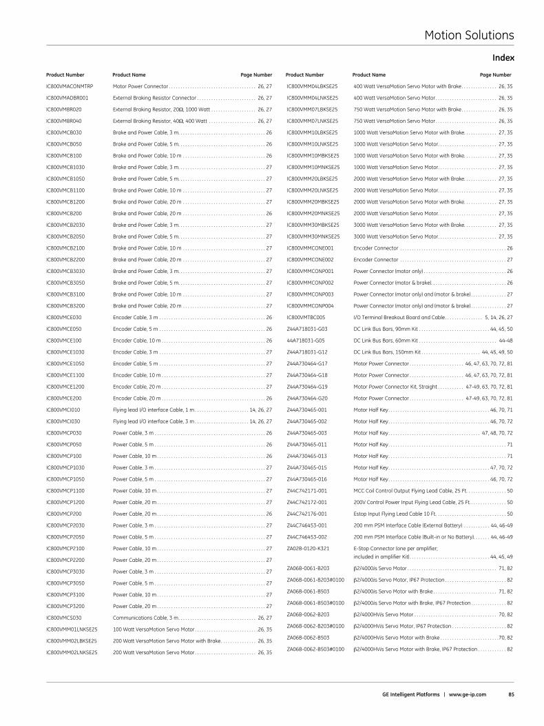
Motion Solutions
GE Intelligent Platforms | www .ge-ip .com 85
Index
Product Number Product Name Page Number Product Number Product Name Page Number
IC800VMACONMTRP Motor Power Connector . . . . . . . . . . . . . . . . . . . . . . . . . . . . . . . . . . . . . 26, 27
IC800VMADBR001 External Braking Resistor Connector . . . . . . . . . . . . . . . . . . . . . . . . . 26, 27
IC800VMBR020 External Braking Resistor, 20Ω, 1000 Watt . . . . . . . . . . . . . . . . . . . 26, 27
IC800VMBR040 External Braking Resistor, 40Ω, 400 Watt . . . . . . . . . . . . . . . . . . . . 26, 27
IC800VMCB030 Brake and Power Cable, 3 m . . . . . . . . . . . . . . . . . . . . . . . . . . . . . . . . . . . . . 26
IC800VMCB050 Brake and Power Cable, 5 m . . . . . . . . . . . . . . . . . . . . . . . . . . . . . . . . . . . . . 26
IC800VMCB100 Brake and Power Cable, 10 m . . . . . . . . . . . . . . . . . . . . . . . . . . . . . . . . . . . 26
IC800VMCB1030 Brake and Power Cable, 3 m . . . . . . . . . . . . . . . . . . . . . . . . . . . . . . . . . . . . . 27
IC800VMCB1050 Brake and Power Cable, 5 m . . . . . . . . . . . . . . . . . . . . . . . . . . . . . . . . . . . . . 27
IC800VMCB1100 Brake and Power Cable, 10 m . . . . . . . . . . . . . . . . . . . . . . . . . . . . . . . . . . . 27
IC800VMCB1200 Brake and Power Cable, 20 m . . . . . . . . . . . . . . . . . . . . . . . . . . . . . . . . . . . 27
IC800VMCB200 Brake and Power Cable, 20 m . . . . . . . . . . . . . . . . . . . . . . . . . . . . . . . . . . . 26
IC800VMCB2030 Brake and Power Cable, 3 m . . . . . . . . . . . . . . . . . . . . . . . . . . . . . . . . . . . . . 27
IC800VMCB2050 Brake and Power Cable, 5 m . . . . . . . . . . . . . . . . . . . . . . . . . . . . . . . . . . . . . 27
IC800VMCB2100 Brake and Power Cable, 10 m . . . . . . . . . . . . . . . . . . . . . . . . . . . . . . . . . . . 27
IC800VMCB2200 Brake and Power Cable, 20 m . . . . . . . . . . . . . . . . . . . . . . . . . . . . . . . . . . . 27
IC800VMCB3030 Brake and Power Cable, 3 m . . . . . . . . . . . . . . . . . . . . . . . . . . . . . . . . . . . . . 27
IC800VMCB3050 Brake and Power Cable, 5 m . . . . . . . . . . . . . . . . . . . . . . . . . . . . . . . . . . . . . 27
IC800VMCB3100 Brake and Power Cable, 10 m . . . . . . . . . . . . . . . . . . . . . . . . . . . . . . . . . . . 27
IC800VMCB3200 Brake and Power Cable, 20 m . . . . . . . . . . . . . . . . . . . . . . . . . . . . . . . . . . . 27
IC800VMCE030 Encoder Cable, 3 m . . . . . . . . . . . . . . . . . . . . . . . . . . . . . . . . . . . . . . . . . . . . . 26
IC800VMCE050 Encoder Cable, 5 m . . . . . . . . . . . . . . . . . . . . . . . . . . . . . . . . . . . . . . . . . . . . . 26
IC800VMCE100 Encoder Cable, 10 m . . . . . . . . . . . . . . . . . . . . . . . . . . . . . . . . . . . . . . . . . . . . 26
IC800VMCE1030 Encoder Cable, 3 m . . . . . . . . . . . . . . . . . . . . . . . . . . . . . . . . . . . . . . . . . . . . . 27
IC800VMCE1050 Encoder Cable, 5 m . . . . . . . . . . . . . . . . . . . . . . . . . . . . . . . . . . . . . . . . . . . . . 27
IC800VMCE1100 Encoder Cable, 10 m . . . . . . . . . . . . . . . . . . . . . . . . . . . . . . . . . . . . . . . . . . . . 27
IC800VMCE1200 Encoder Cable, 20 m . . . . . . . . . . . . . . . . . . . . . . . . . . . . . . . . . . . . . . . . . . . . 27
IC800VMCE200 Encoder Cable, 20 m . . . . . . . . . . . . . . . . . . . . . . . . . . . . . . . . . . . . . . . . . . . . 26
IC800VMCI010 Flying lead I/O interface Cable, 1 m . . . . . . . . . . . . . . . . . . . . . . . 14, 26, 27
IC800VMCI030 Flying lead I/O interface Cable, 3 m . . . . . . . . . . . . . . . . . . . . . . . 14, 26, 27
IC800VMCP030 Power Cable, 3 m . . . . . . . . . . . . . . . . . . . . . . . . . . . . . . . . . . . . . . . . . . . . . . . 26
IC800VMCP050 Power Cable, 5 m . . . . . . . . . . . . . . . . . . . . . . . . . . . . . . . . . . . . . . . . . . . . . . . 26
IC800VMCP100 Power Cable, 10 m . . . . . . . . . . . . . . . . . . . . . . . . . . . . . . . . . . . . . . . . . . . . . . 26
IC800VMCP1030 Power Cable, 3 m . . . . . . . . . . . . . . . . . . . . . . . . . . . . . . . . . . . . . . . . . . . . . . . 27
IC800VMCP1050 Power Cable, 5 m . . . . . . . . . . . . . . . . . . . . . . . . . . . . . . . . . . . . . . . . . . . . . . . 27
IC800VMCP1100 Power Cable, 10 m . . . . . . . . . . . . . . . . . . . . . . . . . . . . . . . . . . . . . . . . . . . . . . 27
IC800VMCP1200 Power Cable, 20 m . . . . . . . . . . . . . . . . . . . . . . . . . . . . . . . . . . . . . . . . . . . . . . 27
IC800VMCP200 Power Cable, 20 m . . . . . . . . . . . . . . . . . . . . . . . . . . . . . . . . . . . . . . . . . . . . . . 26
IC800VMCP2030 Power Cable, 3 m . . . . . . . . . . . . . . . . . . . . . . . . . . . . . . . . . . . . . . . . . . . . . . . 27
IC800VMCP2050 Power Cable, 5 m . . . . . . . . . . . . . . . . . . . . . . . . . . . . . . . . . . . . . . . . . . . . . . . 27
IC800VMCP2100 Power Cable, 10 m . . . . . . . . . . . . . . . . . . . . . . . . . . . . . . . . . . . . . . . . . . . . . . 27
IC800VMCP2200 Power Cable, 20 m . . . . . . . . . . . . . . . . . . . . . . . . . . . . . . . . . . . . . . . . . . . . . . 27
IC800VMCP3030 Power Cable, 3 m . . . . . . . . . . . . . . . . . . . . . . . . . . . . . . . . . . . . . . . . . . . . . . . 27
IC800VMCP3050 Power Cable, 5 m . . . . . . . . . . . . . . . . . . . . . . . . . . . . . . . . . . . . . . . . . . . . . . . 27
IC800VMCP3100 Power Cable, 10 m . . . . . . . . . . . . . . . . . . . . . . . . . . . . . . . . . . . . . . . . . . . . . . 27
IC800VMCP3200 Power Cable, 20 m . . . . . . . . . . . . . . . . . . . . . . . . . . . . . . . . . . . . . . . . . . . . . . 27
IC800VMCS030 Communications Cable, 3 m . . . . . . . . . . . . . . . . . . . . . . . . . . . . . . . . . 26, 27
IC800VMM01LNKSE25 100 Watt VersaMotion Servo Motor . . . . . . . . . . . . . . . . . . . . . . . . . . .26, 35
IC800VMM02LBKSE25 200 Watt VersaMotion Servo Motor with Brake . . . . . . . . . . . . . . . 26, 35
IC800VMM02LNKSE25 200 Watt VersaMotion Servo Motor . . . . . . . . . . . . . . . . . . . . . . . . . . 26, 35
IC800VMM04LBKSE25 400 Watt VersaMotion Servo Motor with Brake . . . . . . . . . . . . . . . 26, 35
IC800VMM04LNKSE25 400 Watt VersaMotion Servo Motor . . . . . . . . . . . . . . . . . . . . . . . . . . 26, 35
IC800VMM07LBKSE25 750 Watt VersaMotion Servo Motor with Brake . . . . . . . . . . . . . . . 26, 35
IC800VMM07LNKSE25 750 Watt VersaMotion Servo Motor . . . . . . . . . . . . . . . . . . . . . . . . . . 26, 35
IC800VMM10LBKSE25 1000 Watt VersaMotion Servo Motor with Brake . . . . . . . . . . . . . . 27, 35
IC800VMM10LNKSE25 1000 Watt VersaMotion Servo Motor . . . . . . . . . . . . . . . . . . . . . . . . . 27, 35
IC800VMM10MBKSE25 1000 Watt VersaMotion Servo Motor with Brake . . . . . . . . . . . . . . 27, 35
IC800VMM10MNKSE25 1000 Watt VersaMotion Servo Motor . . . . . . . . . . . . . . . . . . . . . . . . . 27, 35
IC800VMM20LBKSE25 2000 Watt VersaMotion Servo Motor with Brake . . . . . . . . . . . . . . 27, 35
IC800VMM20LNKSE25 2000 Watt VersaMotion Servo Motor . . . . . . . . . . . . . . . . . . . . . . . . . 27, 35
IC800VMM20MBKSE25 2000 Watt VersaMotion Servo Motor with Brake . . . . . . . . . . . . . . 27, 35
IC800VMM20M NKSE25 2000 Watt VersaMotion Servo Motor . . . . . . . . . . . . . . . . . . . . . . . . . 27, 35
IC800VMM30MBKSE25 3000 Watt VersaMotion Servo Motor with Brake . . . . . . . . . . . . . . 27, 35
IC800VMM30MNKSE25 3000 Watt VersaMotion Servo Motor . . . . . . . . . . . . . . . . . . . . . . . . . 27, 35
IC800VMMCONE001 Encoder Connector . . . . . . . . . . . . . . . . . . . . . . . . . . . . . . . . . . . . . . . . . . . . . 26
IC800VMMCONE002 Encoder Connector . . . . . . . . . . . . . . . . . . . . . . . . . . . . . . . . . . . . . . . . . . . . . 27
IC800VMMCONP001 Power Connector (motor only) . . . . . . . . . . . . . . . . . . . . . . . . . . . . . . . . . . . 26
IC800VMMCONP002 Power Connector (motor & brake) . . . . . . . . . . . . . . . . . . . . . . . . . . . . . . . . 26
IC800VMMCONP003 Power Connector (motor only) and (motor & brake) . . . . . . . . . . . . . . . 27
IC800VMMCONP004 Power Connector (motor only) and (motor & brake) . . . . . . . . . . . . . . . 27
IC800VMTBC005 I/O Terminal Breakout Board and Cable . . . . . . . . . . . . . . . . 5, 14, 26, 27
Z44A718031-G03 DC Link Bus Bars, 90mm Kit . . . . . . . . . . . . . . . . . . . . . . . . . . . . . . 44, 45, 50
44A718031-G05 DC Link Bus Bars, 60mm Kit . . . . . . . . . . . . . . . . . . . . . . . . . . . . . . . . . 44-48
Z44A718031-G12 DC Link Bus Bars, 150mm Kit . . . . . . . . . . . . . . . . . . . . . . . . . 44, 45, 49, 50
Z44A730464-G17 Motor Power Connector . . . . . . . . . . . . . . . . . . . . . . . 46, 47, 63, 70, 72, 81
Z44A730464-G18 Motor Power Connector . . . . . . . . . . . . . . . . . . . . . . . 46, 47, 63, 70, 72, 81
Z44A730464-G19 Motor Power Connector Kit, Straight . . . . . . . . . . . 47-49, 63, 70, 72, 81
Z44A730464-G20 Motor Power Connector . . . . . . . . . . . . . . . . . . . . . . . 47-49, 63, 70, 72, 81
Z44A730465-001 Motor Half Key . . . . . . . . . . . . . . . . . . . . . . . . . . . . . . . . . . . . . . . . . . . 46, 70, 71
Z44A730465-002 Motor Half Key . . . . . . . . . . . . . . . . . . . . . . . . . . . . . . . . . . . . . . . . . . . 46, 70, 72
Z44A730465-003 Motor Half Key . . . . . . . . . . . . . . . . . . . . . . . . . . . . . . . . . . . . . . . 47, 48, 70, 72
Z44A730465-011 Motor Half Key . . . . . . . . . . . . . . . . . . . . . . . . . . . . . . . . . . . . . . . . . . . . . . . . . . 71
Z44A730465-013 Motor Half Key . . . . . . . . . . . . . . . . . . . . . . . . . . . . . . . . . . . . . . . . . . . . . . . . . . 71
Z44A730465-015 Motor Half Key . . . . . . . . . . . . . . . . . . . . . . . . . . . . . . . . . . . . . . . . . . . 47, 70, 72
Z44A730465-016 Motor Half Key . . . . . . . . . . . . . . . . . . . . . . . . . . . . . . . . . . . . . . . . . . . 46, 70, 72
Z44C742171-001 MCC Coil Control Output Flying Lead Cable, 25 Ft . . . . . . . . . . . . . . . . . 50
Z44C742172-001 200V Control Power Input Flying Lead Cable, 25 Ft . . . . . . . . . . . . . . . . 50
Z44C742176-001 Estop Input Flying Lead Cable 10 Ft . . . . . . . . . . . . . . . . . . . . . . . . . . . . . . 50
Z44C746453-001 200 mm PSM Interface Cable (External Battery) . . . . . . . . . . . 44, 46-49
Z44C746453-002 200 mm PSM Interface Cable (Built-in or No Battery) . . . . . . . 44, 46-49
ZA02B-0120-K321 E-Stop Connector (one per amplifier;
included in amplifier Kit) . . . . . . . . . . . . . . . . . . . . . . . . . . . . . . . . . . 44, 45, 49
ZA06B-0061-B203 β2/4000is Servo Motor . . . . . . . . . . . . . . . . . . . . . . . . . . . . . . . . . . . . . . 71, 82
ZA06B-0061-B203#0100 β2/4000is Servo Motor, IP67 Protection . . . . . . . . . . . . . . . . . . . . . . . . . . 82
ZA06B-0061-B503 β2/4000is Servo Motor with Brake . . . . . . . . . . . . . . . . . . . . . . . . . . . 71, 82
ZA06B-0061-B503#0100 β2/4000is Servo Motor with Brake, IP67 Protection . . . . . . . . . . . . . . . 82
ZA06B-0062-B203 β2/4000HVis Servo Motor . . . . . . . . . . . . . . . . . . . . . . . . . . . . . . . . . . . 70, 82
ZA06B-0062-B203#0100 β2/4000HVis Servo Motor, IP67 Protection . . . . . . . . . . . . . . . . . . . . . . . 82
ZA06B-0062-B503 β2/4000HVis Servo Motor with Brake . . . . . . . . . . . . . . . . . . . . . . . . .70, 82
ZA06B-0062-B503#0100 β2/4000HVis Servo Motor with Brake, IP67 Protection . . . . . . . . . . . . 82
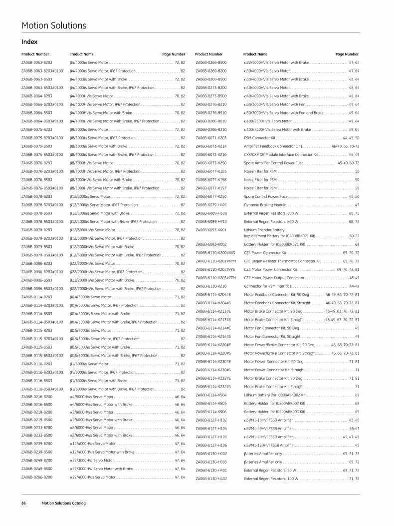
Motion Solutions
86 Motion Solutions Catalog
Product Number Product Name Page Number Product Number Product Name Page Number
ZA06B-0063-B203 β4/4000is Servo Motor . . . . . . . . . . . . . . . . . . . . . . . . . . . . . . . . . . . . . . 72, 82
ZA06B-0063-B203#0100 β4/4000is Servo Motor, IP67 Protection . . . . . . . . . . . . . . . . . . . . . . . . . . 82
ZA06B-0063-B503 β4/4000is Servo Motor with Brake . . . . . . . . . . . . . . . . . . . . . . . . . . . 72, 82
ZA06B-0063-B503#0100 β4/4000is Servo Motor with Brake, IP67 Protection . . . . . . . . . . . . . . . 82
ZA06B-0064-B203 β4/4000HVis Servo Motor . . . . . . . . . . . . . . . . . . . . . . . . . . . . . . . . . . . 70, 82
ZA06B-0064-B203#0100 β4/4000HVis Servo Motor, IP67 Protection . . . . . . . . . . . . . . . . . . . . . . . 82
ZA06B-0064-B503 β4/4000HVis Servo Motor with Brake . . . . . . . . . . . . . . . . . . . . . . . . 70, 82
ZA06B-0064-B503#0100 β4/4000HVis Servo Motor with Brake, IP67 Protection . . . . . . . . . . . . 82
ZA06B-0075-B203 β8/3000is Servo Motor . . . . . . . . . . . . . . . . . . . . . . . . . . . . . . . . . . . . . . 72, 82
ZA06B-0075-B203#0100 β8/3000is Servo Motor, IP67 Protection . . . . . . . . . . . . . . . . . . . . . . . . . . 82
ZA06B-0075-B503 β8/3000is Servo Motor with Brake . . . . . . . . . . . . . . . . . . . . . . . . . . . 72, 82
ZA06B-0075-B503#0100 β8/3000is Servo Motor with Brake, IP67 Protection . . . . . . . . . . . . . . . 82
ZA06B-0076-B203 β8/3000HVis Servo Motor . . . . . . . . . . . . . . . . . . . . . . . . . . . . . . . . . . . 70, 82
ZA06B-0076-B203#0100 β8/3000HVis Servo Motor, IP67 Protection . . . . . . . . . . . . . . . . . . . . . . . 82
ZA06B-0076-B503 β8/3000HVis Servo Motor with Brake . . . . . . . . . . . . . . . . . . . . . . . . 70, 82
ZA06B-0076-B503#0100 β8/3000HVis Servo Motor with Brake, IP67 Protection . . . . . . . . . . . . 82
ZA06B-0078-B203 β12/3000is Servo Motor . . . . . . . . . . . . . . . . . . . . . . . . . . . . . . . . . . . . . 72, 82
ZA06B-0078-B203#0100 β12/3000is Servo Motor, IP67 Protection . . . . . . . . . . . . . . . . . . . . . . . . . 82
ZA06B-0078-B503 β12/3000is Servo Motor with Brake . . . . . . . . . . . . . . . . . . . . . . . . . . 72, 82
ZA06B-0078-B503#0100 β12/3000is Servo Motor with Brake, IP67 Protection . . . . . . . . . . . . . . 82
ZA06B-0079-B203 β12/3000HVis Servo Motor . . . . . . . . . . . . . . . . . . . . . . . . . . . . . . . . . . 70, 82
ZA06B-0079-B203#0100 β12/3000HVis Servo Motor, IP67 Protection . . . . . . . . . . . . . . . . . . . . . . 82
ZA06B-0079-B503 β12/3000HVis Servo Motor with Brake . . . . . . . . . . . . . . . . . . . . . . . 70, 82
ZA06B-0079-B503#0100 β12/3000HVis Servo Motor with Brake, IP67 Protection . . . . . . . . . . . 82
ZA06B-0086-B203 β22/2000HVis Servo Motor . . . . . . . . . . . . . . . . . . . . . . . . . . . . . . . . . . 70, 82
ZA06B-0086-B203#0100 β22/2000HVis Servo Motor, IP67 Protection . . . . . . . . . . . . . . . . . . . . . . 82
ZA06B-0086-B503 β22/2000HVis Servo Motor with Brake . . . . . . . . . . . . . . . . . . . . . . . 70, 82
ZA06B-0086-B503#0100 β22/2000HVis Servo Motor with Brake, IP67 Protection . . . . . . . . . . . 82
ZA06B-0114-B203 β0 .4/5000is Servo Motor . . . . . . . . . . . . . . . . . . . . . . . . . . . . . . . . . . . . 71, 82
ZA06B-0114-B203#0100 β0 .4/5000is Servo Motor, IP67 Protection . . . . . . . . . . . . . . . . . . . . . . . . 82
ZA06B-0114-B503 β0 .4/5000is Servo Motor with Brake . . . . . . . . . . . . . . . . . . . . . . . . . 71, 82
ZA06B-0114-B503#0100 β0 .4/5000is Servo Motor with Brake, IP67 Protection . . . . . . . . . . . . . 82
ZA06B-0115-B203 β0 .5/6000is Servo Motor . . . . . . . . . . . . . . . . . . . . . . . . . . . . . . . . . . . . 71, 82
ZA06B-0115-B203#0100 β0 .5/6000is Servo Motor, IP67 Protection . . . . . . . . . . . . . . . . . . . . . . . . 82
ZA06B-0115-B503 β0 .5/6000is Servo Motor with Brake . . . . . . . . . . . . . . . . . . . . . . . . . 71, 82
ZA06B-0115-B503#0100 β0 .5/6000is Servo Motor with Brake, IP67 Protection . . . . . . . . . . . . . 82
ZA06B-0116-B203 β1/6000is Servo Motor . . . . . . . . . . . . . . . . . . . . . . . . . . . . . . . . . . . . . . 71, 82
ZA06B-0116-B203#0100 β1/6000is Servo Motor, IP67 Protection . . . . . . . . . . . . . . . . . . . . . . . . . . 82
ZA06B-0116-B503 β1/6000is Servo Motor with Brake . . . . . . . . . . . . . . . . . . . . . . . . . . . 71, 82
ZA06B-0116-B503#0100 β1/6000is Servo Motor with Brake, IP67 Protection . . . . . . . . . . . . . . . 82
ZA06B-0216-B200 α4/5000HVis Servo Motor . . . . . . . . . . . . . . . . . . . . . . . . . . . . . . . . . . . 46, 64
ZA06B-0216-B500 α4/5000HVis Servo Motor with Brake . . . . . . . . . . . . . . . . . . . . . . . . 46, 64
ZA06B-0219-B200 α2/6000HVis Servo Motor . . . . . . . . . . . . . . . . . . . . . . . . . . . . . . . . . . . 46, 64
ZA06B-0219-B500 α2/6000HVis Servo Motor with Brake . . . . . . . . . . . . . . . . . . . . . . . . 46, 64
ZA06B-0233-B200 α8/6000HVis Servo Motor . . . . . . . . . . . . . . . . . . . . . . . . . . . . . . . . . . . 46, 64
ZA06B-0233-B500 α8/6000HVis Servo Motor with Brake . . . . . . . . . . . . . . . . . . . . . . . . .46, 64
ZA06B-0239-B200 α12/4000HVis Servo Motor . . . . . . . . . . . . . . . . . . . . . . . . . . . . . . . . . . 47, 64
ZA06B-0239-B500 α12/4000HVis Servo Motor with Brake . . . . . . . . . . . . . . . . . . . . . . . .47, 64
ZA06B-0249-B200 α22/3000HVi Servo Motor . . . . . . . . . . . . . . . . . . . . . . . . . . . . . . . . . . . 47, 64
ZA06B-0249-B500 α22/3000HVi Servo Motor with Brake . . . . . . . . . . . . . . . . . . . . . . . . 47, 64
ZA06B-0266-B200 α22/4000HVis Servo Motor . . . . . . . . . . . . . . . . . . . . . . . . . . . . . . . . . . 47, 64
ZA06B-0266-B500 α22/4000HVis Servo Motor with Brake . . . . . . . . . . . . . . . . . . . . . . . 47, 64
ZA06B-0269-B200 α30/4000HVis Servo Motor . . . . . . . . . . . . . . . . . . . . . . . . . . . . . . . . . . 47, 64
ZA06B-0269-B500 α30/4000HVis Servo Motor with Brake . . . . . . . . . . . . . . . . . . . . . . . 48, 64
ZA06B-0273-B200 α40/4000HVis Servo Motor . . . . . . . . . . . . . . . . . . . . . . . . . . . . . . . . . . 48, 64
ZA06B-0273-B500 α40/4000HVis Servo Motor with Brake . . . . . . . . . . . . . . . . . . . . . . . 48, 64
ZA06B-0276-B210 α50/3000HVis Servo Motor with Fan . . . . . . . . . . . . . . . . . . . . . . . . . 49, 64
ZA06B-0276-B510 α50/3000HVis Servo Motor with Fan and Brake . . . . . . . . . . . . . . 49, 64
ZA06B-0286-B010 α100/2500HVis Servo Motor . . . . . . . . . . . . . . . . . . . . . . . . . . . . . . . . 49, 64
ZA06B-0286-B310 α100/2500HVis Servo Motor with Brake . . . . . . . . . . . . . . . . . . . . . 49, 64
ZA06B-6071-K203 PSM Connector Kit . . . . . . . . . . . . . . . . . . . . . . . . . . . . . . . . . . . . . . . 44, 45, 50
ZA06B-6073-K214 Amplifier Feedback Connector (JF1) . . . . . . . . . . . . . . . . 46-49, 63, 70-72
ZA06B-6073-K216 CX8/CX9 DB Module Interface Connector Kit . . . . . . . . . . . . . . . . . 45, 49
ZA06B-6073-K250 Spare Amplifier Control Power Fuse . . . . . . . . . . . . . . . . . . . 45-49, 69-72
ZA06B-6077-K155 Noise Filter for PSM . . . . . . . . . . . . . . . . . . . . . . . . . . . . . . . . . . . . . . . . . . . . . 50
ZA06B-6077-K156 Noise Filter for PSM . . . . . . . . . . . . . . . . . . . . . . . . . . . . . . . . . . . . . . . . . . . . . 50
ZA06B-6077-K157 Noise Filter for PSM . . . . . . . . . . . . . . . . . . . . . . . . . . . . . . . . . . . . . . . . . . . . . 50
ZA06B-6077-K250 Spare Control Power Fuse . . . . . . . . . . . . . . . . . . . . . . . . . . . . . . . . . . . 45, 50
ZA06B-6079-H401 Dynamic Braking Module . . . . . . . . . . . . . . . . . . . . . . . . . . . . . . . . . . . . . . . . 49
ZA06B-6089-H500 External Regen Resistors, 200 W . . . . . . . . . . . . . . . . . . . . . . . . . . . . . 68, 72
ZA06B-6089-H713 External Regen Resistors, 800 W . . . . . . . . . . . . . . . . . . . . . . . . . . . . . 68, 72
ZA06B-6093-K001 Lithium Encoder Battery
(replacement battery for IC800BBK021 Kit) . . . . . . . . . . . . . . . . . . . 69-72
ZA06B-6093-K002 Battery Holder (for IC800BBK021 Kit) . . . . . . . . . . . . . . . . . . . . . . . . . . . . . 69
ZA06B-6110-K200#XXS CZ4 Power Connector Kit . . . . . . . . . . . . . . . . . . . . . . . . . . . . . . . . . 69, 70, 72
ZA06B-6110-K201#XYM CZ6 Regen Resistor Thermostat Connector Kit . . . . . . . . . . . . . 69, 70, 72
ZA06B-6110-K202#YYS CZ5 Motor Power Connector Kit . . . . . . . . . . . . . . . . . . . . . . 69, 70, 72, 81
ZA06B-6110-K203#ZZM CZ2 Motor Power Output Connector . . . . . . . . . . . . . . . . . . . . . . . . . . 45-49
ZA06B-6110-K210 Connector for PSM Interface . . . . . . . . . . . . . . . . . . . . . . . . . . . . . . . . . 44-49
ZA06B-6114-K204#E Motor Feedback Connector Kit, 90 Deg . . . . . . . . 46-49, 63, 70-72, 81
ZA06B-6114-K204#S Motor Feedback Connector Kit, Straight . . . . . . . . 46-49, 63, 70-72, 81
ZA06B-6114-K213#E Motor Brake Connector Kit, 90 Deg . . . . . . . . . . . . 46-49, 63, 70, 72, 81
ZA06B-6114-K213#S Motor Brake Connector Kit, Straight . . . . . . . . . . . . 46-49, 63, 70, 72, 81
ZA06B-6114-K214#E Motor Fan Connector Kit, 90 Deg . . . . . . . . . . . . . . . . . . . . . . . . . . . . . . . . 49
ZA06B-6114-K214#S Motor Fan Connector Kit, Straight . . . . . . . . . . . . . . . . . . . . . . . . . . . . . . . 49
ZA06B-6114-K220#E Motor Power/Brake Connector Kit, 90 Deg . . . . . . . . . 46, 63, 70-72, 81
ZA06B-6114-K220#S Motor Power/Brake Connector Kit, Straight . . . . . . . . . 46, 63, 70-72, 81
ZA06B-6114-K230#E Motor Power Connector Kit, 90 Deg . . . . . . . . . . . . . . . . . . . . . . . . . . 71, 81
ZA06B-6114-K230#S Motor Power Connector Kit, Straight . . . . . . . . . . . . . . . . . . . . . . . . . . . . . 71
ZA06B-6114-K232#E Motor Brake Connector Kit, 90 Deg . . . . . . . . . . . . . . . . . . . . . . . . . . 71, 81
ZA06B-6114-K232#S Motor Brake Connector Kit, Straight . . . . . . . . . . . . . . . . . . . . . . . . . . . . . 71
ZA06B-6114-K504 Lithium Battery (for IC800ABK002 Kit) . . . . . . . . . . . . . . . . . . . . . . . . . . . . 69
ZA06B-6114-K505 Battery Holder (for IC800ABK002 Kit) . . . . . . . . . . . . . . . . . . . . . . . . . . . . . 69
ZA06B-6114-K506 Battery Holder (for IC800ABK003 Kit) . . . . . . . . . . . . . . . . . . . . . . . . . . . . . 69
ZA06B-6127-H102 αSVM1-10HVi FSSB Amplifier . . . . . . . . . . . . . . . . . . . . . . . . . . . . . . . . 45, 46
ZA06B-6127-H104 αSVM1-40HVi FSSB Amplifier . . . . . . . . . . . . . . . . . . . . . . . . . . . . . . . . 45-47
ZA06B-6127-H105 αSVM1-80HVi FSSB Amplifier . . . . . . . . . . . . . . . . . . . . . . . . . . . . . 45, 47, 48
ZA06B-6127-H106 αSVM1-180HVi FSSB Amplifier . . . . . . . . . . . . . . . . . . . . . . . . . . . . . . . . . . . 45
ZA06B-6130-H002 βi series Amplifier only . . . . . . . . . . . . . . . . . . . . . . . . . . . . . . . . . . . 69, 71, 72
ZA06B-6130-H003 βi series Amplifier only . . . . . . . . . . . . . . . . . . . . . . . . . . . . . . . . . . . . . . 69, 72
ZA06B-6130-H401 External Regen Resistors, 20 W . . . . . . . . . . . . . . . . . . . . . . . . . . . 69, 71, 72
ZA06B-6130-H402 External Regen Resistors, 100 W . . . . . . . . . . . . . . . . . . . . . . . . . . . . . 71, 72
Index
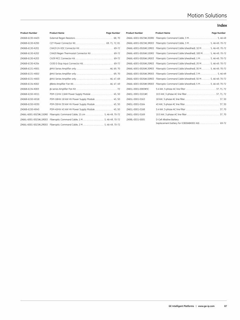
Motion Solutions
GE Intelligent Platforms | www .ge-ip .com 87
Product Number Product Name Page Number Product Number Product Name Page Number
ZA06B-6130-H403 External Regen Resistors . . . . . . . . . . . . . . . . . . . . . . . . . . . . . . . . . . . . 68, 70
ZA06B-6130-K200 CZ7 Power Connector Kit . . . . . . . . . . . . . . . . . . . . . . . . . . . . . 69, 71, 72, 81
ZA06B-6130-K201 CXA19 24 VDC Connector Kit . . . . . . . . . . . . . . . . . . . . . . . . . . . . . . . . 69-72
ZA06B-6130-K202 CXA20 Regen Thermostat Connector Kit . . . . . . . . . . . . . . . . . . . . . 69-72
ZA06B-6130-K203 CX29 MCC Connector Kit . . . . . . . . . . . . . . . . . . . . . . . . . . . . . . . . . . . . 69-72
ZA06B-6130-K204 CX30 E-Stop Input Connector Kit . . . . . . . . . . . . . . . . . . . . . . . . . . . . . 69-72
ZA06B-6131-H001 βHVi Series Amplifier only . . . . . . . . . . . . . . . . . . . . . . . . . . . . . . . . 46, 69, 70
ZA06B-6131-H002 βHVi Series Amplifier only . . . . . . . . . . . . . . . . . . . . . . . . . . . . . . . . . . . 69, 70
ZA06B-6131-H003 βHVi Series Amplifier only . . . . . . . . . . . . . . . . . . . . . . . . . . . . . . . . 46, 47, 69
ZA06B-6134-K002 βBeta Amplifier Fan Kit . . . . . . . . . . . . . . . . . . . . . . . . . . . . . . . . . . . 46, 47, 49
ZA06B-6134-K003 βi series Amplifier Fan Kit . . . . . . . . . . . . . . . . . . . . . . . . . . . . . . . . . . . . . . . 72
ZA06B-6150-H011 PSM-11HVi 11kW Power Supply Module . . . . . . . . . . . . . . . . . . . . . 45, 50
ZA06B-6150-H018 PSM-18HVi 18 kW HV Power Supply Module . . . . . . . . . . . . . . . . . 45, 50
ZA06B-6150-H030 PSM-30HVi 30 kW HV Power Supply Module . . . . . . . . . . . . . . . . . 45, 50
ZA06B-6150-H045 PSM-45HVi 45 kW HV Power Supply Module . . . . . . . . . . . . . . . . . 45, 50
ZA66L-6001-0023#L150R0 Fiberoptic Command Cable, 15 cm . . . . . . . . . . . . . . . . . 5, 46-49, 70-72
ZA66L-6001-0023#L1R003 Fiberoptic Command Cable, 1 M . . . . . . . . . . . . . . . . . . . . 5, 46-49, 70-72
ZA66L-6001-0023#L2R003 Fiberoptic Command Cable, 2 M . . . . . . . . . . . . . . . . . . . . 5, 46-49, 70-72
ZA66L-6001-0023#L300R0 Fiberoptic Command Cable, 3 M . . . . . . . . . . . . . . . . . . . . . . . . . . . 5, 46-49
ZA66L-6001-0023#L3R003 Fiberoptic Command Cable, 3 M . . . . . . . . . . . . . . . . . . . . 5, 46-49, 70-72
ZA66L-6001-0026#L10R03 Fiberoptic Command Cable (sheathed), 10 M . . . . . . . . 5, 46-49, 70-72
ZA66L-6001-0026#L100R3 Fiberoptic Command Cable (sheathed), 100 M . . . . . . . 5, 46-49, 70-72
ZA66L-6001-0026#L1R003 Fiberoptic Command Cable (sheathed), 1 M . . . . . . . . . 5, 46-49, 70-72
ZA66L-6001-0026#L20R03 Fiberoptic Command Cable (sheathed), 20 M . . . . . . . . 5, 46-49, 70-72
ZA66L-6001-0026#L30R03 Fiberoptic Command Cable (sheathed), 30 M . . . . . . . . 5, 46-49, 70-72
ZA66L-6001-0026#L3R003 Fiberoptic Command Cable (sheathed), 3 M . . . . . . . . . . . . . . . . 5, 46-49
ZA66L-6001-0026#L50R03 Fiberoptic Command Cable (sheathed), 50 M . . . . . . . . 5, 46-49, 70-72
ZA66L-6001-0026#L5R003 Fiberoptic Command Cable (sheathed), 5 M . . . . . . . . . .5, 46-49, 70-72
ZA81L-0001-0083#3C 5 .4 kW, 3-phase AC line filter . . . . . . . . . . . . . . . . . . . . . . . . . . . . . 37, 71, 72
ZA81L-0001-0101#C 10 .5 kW, 3-phase AC line filter . . . . . . . . . . . . . . . . . . . . . . . . . . . . 37, 71, 72
ZA81L-0001-0163 18 kW, 3-phase AC line filter . . . . . . . . . . . . . . . . . . . . . . . . . . . . . . . . . 37, 50
ZA81L-0001-0164 45 kW, 3-phase AC line filter . . . . . . . . . . . . . . . . . . . . . . . . . . . . . . . . . 37, 50
ZA81L-0001-0168 5 .4 kW, 3-phase AC line filter . . . . . . . . . . . . . . . . . . . . . . . . . . . . . . . . 37, 70
ZA81L-0001-0169 10 .5 kW, 3-phase AC line filter . . . . . . . . . . . . . . . . . . . . . . . . . . . . . . . 37, 70
ZA98L-0031-0005 D-Cell Alkaline Battery
(replacement battery for IC800ABK001 Kit) . . . . . . . . . . . . . . . . . . . 69-72
Index

Motion Solutions
88 Motion Solutions Catalog


01 .12 GFA-483U
©2012 GE Intelligent Platforms, Inc . All rights reserved .*Trademark of GE Intelligent Platforms, Inc .All other brands or names are property of their respective holders .
GE Intelligent Platforms Contact Information
Americas: 1 800 433 2682 or 1 434 978 5100 Global regional phone numbers are listed by location on our web site at www .ge-ip .com/contact
www .ge-ip .com