
More information 14 Dimensions 14 Directional spool valves, … · 2020-04-24 · – Pressure...
16
RE 22334, edition: 2013-04, Bosch Rexroth AG Directional spool valves, directly operated, with manual and fluid logics actuation Features ▶ 4/3-, 4/2- or 3/2-way version ▶ Porting pattern according to ISO 4401-05-04-0-05 and NFPA T3.5.1 R2-2002 D05 ▶ Types of actuation: – Hand lever – Pneumatic – Hydraulic Contents Features 1 Ordering code 2 Symbols 3 Types of actuation 4, 5 Function, section 6 Technical data 7 Characteristic curves 8 Performance limits 9, 10 Dimensions 11 … 14 More information 14 ▶ Size 10 ▶ Component series 5X ▶ Maximum operating pressure 350 bar [5076 psi] ▶ Maximum flow 160 l/min [42.3 US gpm] RE 22334 Edition: 2013-04 Replaces: 22331 Type WMM, WN and WP
Transcript of More information 14 Dimensions 14 Directional spool valves, … · 2020-04-24 · – Pressure...

Inhalt
Features 1Contents 1Ordering code 2Symbols 3Types of actuation: Type WMM 4Types of actuation: WN and WP 5Function, section 6Technical data (for applications outside these parameters, please consult us!) 7Characteristic curves (measured with HLP46, ϑOil = 40 ± 5 °C [104 ± 9 °F]) 8Performance limits (measured with HLP46, ϑOil = 40 ± 5 °C [104 ± 9 °F]) 9Performance limits (measured with HLP46, ϑOil = 40 ± 5 °C [104 ± 9 °F]) 10Dimensions: Type WMM (dimensions in mm [inch]) 11Dimensions: Type WM (dimensions in mm [inch]) 12Dimensions: Type WP (dimensions in mm [inch]) 13Dimensions 14More information 14Notes 15Notes 16
RE 22334, edition: 2013-04, Bosch Rexroth AG
Directional spool valves, directly operated, with manual and fluid logics actuation
Features
▶ 4/3-, 4/2- or 3/2-way version ▶ Porting pattern according to ISO 4401-05-04-0-05 and
NFPA T3.5.1 R2-2002 D05 ▶ Types of actuation:
– Hand lever – Pneumatic – Hydraulic
Contents
Features 1Ordering code 2Symbols 3Types of actuation 4, 5Function, section 6Technical data 7Characteristic curves 8Performance limits 9, 10Dimensions 11 … 14More information 14
▶ Size 10 ▶ Component series 5X ▶ Maximum operating pressure 350 bar [5076 psi] ▶ Maximum flow 160 l/min [42.3 US gpm]
RE 22334 Edition: 2013-04Replaces: 22331Type WMM, WN and WP
2/14 WMM; WN; WP | Directional spool valve
Bosch Rexroth AG, RE 22334, edition: 2013-04
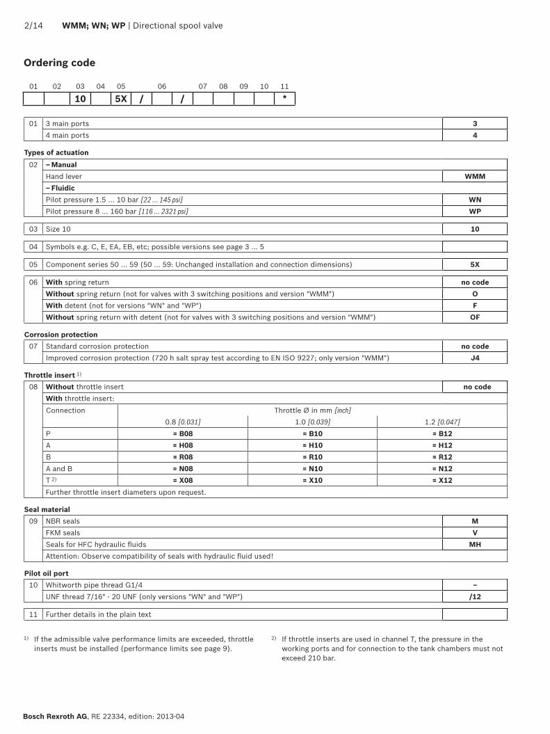
Ordering code
01 3 main ports 34 main ports 4
Types of actuation02 – Manual
Hand lever WMM– FluidicPilot pressure 1.5 … 10 bar [22 … 145 psi] WNPilot pressure 8 … 160 bar [116 … 2321 psi] WP
03 Size 10 10
04 Symbols e.g. C, E, EA, EB, etc; possible versions see page 3 … 5
05 Component series 50 … 59 (50 … 59: Unchanged installation and connection dimensions) 5X
06 With spring return no codeWithout spring return (not for valves with 3 switching positions and version "WMM") OWith detent (not for versions "WN" and "WP") FWithout spring return with detent (not for valves with 3 switching positions and version "WMM") OF
Corrosion protection07 Standard corrosion protection no code
Improved corrosion protection (720 h salt spray test according to EN ISO 9227; only version "WMM") J4
Throttle insert 1) 08 Without throttle insert no code
With throttle insert:Connection Throttle Ø in mm [inch]
0.8 [0.031] 1.0 [0.039] 1.2 [0.047]P = B08 = B10 = B12A = H08 = H10 = H12B = R08 = R10 = R12A and B = N08 = N10 = N12T 2) = X08 = X10 = X12Further throttle insert diameters upon request.
Seal material09 NBR seals M
FKM seals VSeals for HFC hydraulic fluids MHAttention: Observe compatibility of seals with hydraulic fluid used!
Pilot oil port10 Whitworth pipe thread G1/4 –
UNF thread 7/16" - 20 UNF (only versions "WN" and "WP") /12
11 Further details in the plain text
01 02 03 04 05 06 07 08 09 10 11
10 5X / / *
1) If the admissible valve performance limits are exceeded, throttle inserts must be installed (performance limits see page 9).
2) If throttle inserts are used in channel T, the pressure in the working ports and for connection to the tank chambers must not exceed 210 bar.

A B
P T
a b a b
A B
P T
= A
= C
= D
a b
A B
P T
a b
A B
P T
= B
= L
= M
= E 1)
= F
= G
= H
= J
A B
P T
a 0 a 0
A B
P T
b b
A B
P T
a 0 a 0
A B
P T
A B
P T
0 0
A B
P T
b b
= .A 1)
= .B 1)
= R
= T
= U
= V
= W
= P
= Q
= J73
Directional spool valve | WMM; WN; WP 3/14
RE 22334, edition: 2013-04, Bosch Rexroth AG
1) Example: – Symbol E with switching position "a": Ordering code ..EA..
– Symbol E with switching position "b": Ordering code ..EA..
Symbols
4/14 WMM; WN; WP | Directional spool valve
Bosch Rexroth AG, RE 22334, edition: 2013-04
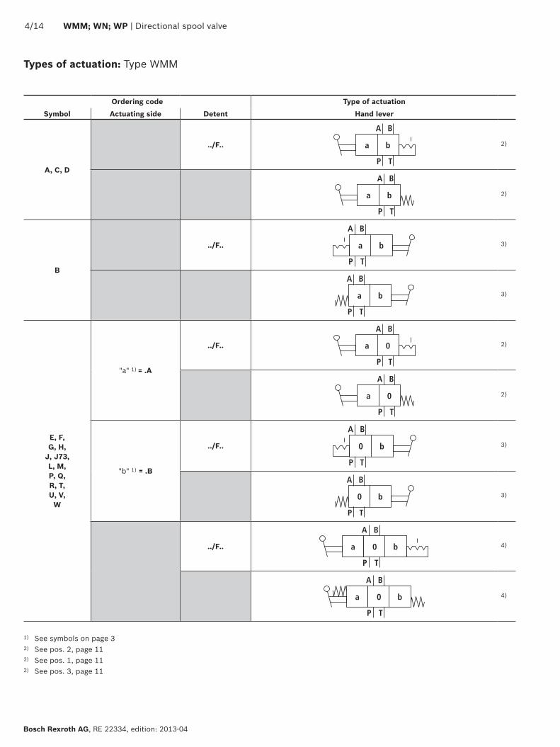
1) See symbols on page 32) See pos. 2, page 112) See pos. 1, page 112) See pos. 3, page 11
Ordering code Type of actuationSymbol Actuating side Detent Hand lever
A, C, D
../F.. a b
A B
P T
2)
a b
A B
P T
2)
B
../F.. a b
A B
P T
3)
a b
A B
P T
3)
E, F, G, H,
J, J73, L, M, P, Q, R, T, U, V,
W
"a" 1) = .A
../F.. a 0
A B
P T
2)
a 0
A B
P T
2)
"b" 1) = .B
../F.. 0 b
A B
P T
3)
0 b
A B
P T
3)
../F.. 0 ba
A B
P T
4)
0 ba
A B
P T
4)
Types of actuation: Type WMM
Directional spool valve | WMM; WN; WP 5/14
RE 22334, edition: 2013-04, Bosch Rexroth AG
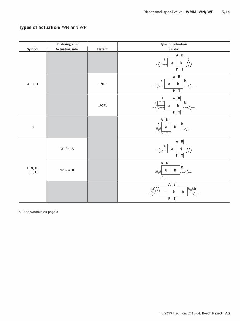
Types of actuation: WN and WP
1) See symbols on page 3
Ordering code Type of actuationSymbol Actuating side Detent Fluidic
A, C, D
a b
A B
P T
ba
../O.. a bb
A B
P T
a
../OF.. a b
A B
P T
ba
B a b
A B
P T
ba
E, G, H, J, L, U
"a" 1) = .A a 0
A B
P T
a
"b" 1) = .B 0 b
A B
P T
b
0 b
A B
P T
ba
a
��� � � �
�� ��� � �
�
��� ���� �� �
�� ��� � �
�
6/14 WMM; WN; WP | Directional spool valve
Bosch Rexroth AG, RE 22334, edition: 2013-04
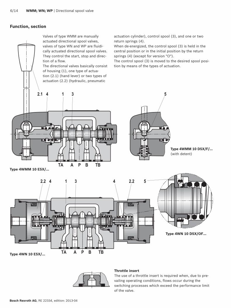
Valves of type WMM are manually actuated directional spool valves, valves of type WN and WP are fluidi-cally actuated directional spool valves.They control the start, stop and direc-tion of a flow.The directional valves basically consist of housing (1), one type of actua-tion (2.1) (hand lever) or two types of actuation (2.2) (hydraulic, pneumatic
Type 4WMM 10 E5X/...
Type 4WMM 10 D5X/F/... (with detent)
Function, section
actuation cylinder), control spool (3), and one or two return springs (4).When de-energized, the control spool (3) is held in the central position or in the initial position by the return springs (4) (except for version "O").The control spool (3) is moved to the desired spool posi-tion by means of the types of actuation.
Type 4WN 10 E5X/…
Type 4WN 10 D5X/OF…
Throttle insertThe use of a throttle insert is required when, due to pre-vailing operating conditions, flows occur during the switching processes which exceed the performance limit of the valve.
Directional spool valve | WMM; WN; WP 7/14
RE 22334, edition: 2013-04, Bosch Rexroth AG
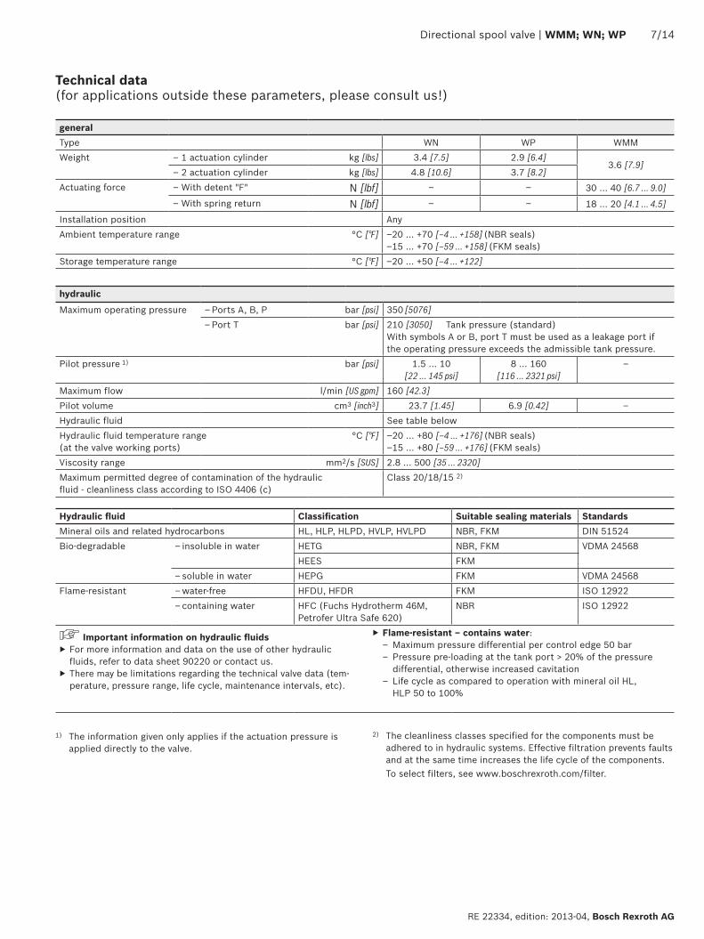
Technical data (for applications outside these parameters, please consult us!)
1) The information given only applies if the actuation pressure is applied directly to the valve.
hydraulic
Maximum operating pressure – Ports A, B, P bar [psi] 350 [5076]– Port T bar [psi] 210 [3050] Tank pressure (standard)
With symbols A or B, port T must be used as a leakage port if the operating pressure exceeds the admissible tank pressure.
Pilot pressure 1) bar [psi] 1.5 … 10 [22 … 145 psi]
8 … 160 [116 … 2321 psi]
–
Maximum flow l/min [US gpm] 160 [42.3]Pilot volume cm3 [inch3] 23.7 [1.45] 6.9 [0.42] –Hydraulic fluid See table belowHydraulic fluid temperature range (at the valve working ports)
°C [°F] –20 … +80 [–4 … +176] (NBR seals)–15 … +80 [–59 … +176] (FKM seals)
Viscosity range mm2/s [SUS] 2.8 … 500 [35 … 2320]Maximum permitted degree of contamination of the hydraulic fluid - cleanliness class according to ISO 4406 (c)
Class 20/18/15 2)
generalType WN WP WMMWeight – 1 actuation cylinder kg [lbs] 3.4 [7.5] 2.9 [6.4]
3.6 [7.9]– 2 actuation cylinder kg [lbs] 4.8 [10.6] 3.7 [8.2]
Actuating force – With detent "F" N [lbf] – – 30 … 40 [6.7 … 9.0]
– With spring return N [lbf] – – 18 … 20 [4.1 … 4.5]
Installation position AnyAmbient temperature range °C [°F] –20 … +70 [–4 … +158] (NBR seals)
–15 … +70 [–59 … +158] (FKM seals)Storage temperature range °C [°F] –20 … +50 [–4 … +122]
Hydraulic fluid Classification Suitable sealing materials StandardsMineral oils and related hydrocarbons HL, HLP, HLPD, HVLP, HVLPD NBR, FKM DIN 51524Bio-degradable – insoluble in water HETG NBR, FKM VDMA 24568
HEES FKM– soluble in water HEPG FKM VDMA 24568
Flame-resistant – water-free HFDU, HFDR FKM ISO 12922– containing water HFC (Fuchs Hydrotherm 46M,
Petrofer Ultra Safe 620)NBR ISO 12922
Important information on hydraulic fluids ▶ For more information and data on the use of other hydraulic fluids, refer to data sheet 90220 or contact us.
▶ There may be limitations regarding the technical valve data (tem-perature, pressure range, life cycle, maintenance intervals, etc).
▶ Flame-resistant – contains water: – Maximum pressure differential per control edge 50 bar – Pressure pre-loading at the tank port > 20% of the pressure differential, otherwise increased cavitation
– Life cycle as compared to operation with mineral oil HL, HLP 50 to 100%
2) The cleanliness classes specified for the components must be adhered to in hydraulic systems. Effective filtration prevents faults and at the same time increases the life cycle of the components.
To select filters, see www.boschrexroth.com/filter.

1234567
9
11
20 403010 50 60 70 80 90 100 110 120
8
4
12
16
20
2426
130 140 15000
8
10
[4] [8] [12] [16] [39.6][20] [24] [28] [30] [32][0]
[0]
[40]
[80]
[120]
[200]
[160]
[240]
[280]
[300]
[377]
20 403010 50 60 70 80 90 100 110 120
8
4
12
16
20
2426
130 140 15000
12
1314151617181920212223
24
[0]
[40]
[80]
[120]
[200]
[160]
[240]
[280]
[300]
[377]
[0] [4] [8] [12] [16] [39.6][20] [24] [28] [30] [32]
8/14 WMM; WN; WP | Directional spool valve
Bosch Rexroth AG, RE 22334, edition: 2013-04
Characteristic curves (measured with HLP46, ϑOil = 40 ± 5 °C [104 ± 9 °F])
∆p-qV characteristic curve
Flow in l/min [US gpm] →
Flow in l/min [US gpm] →
Pres
sure
diff
eren
tial i
n ba
r [p
si] →
Pres
sure
diff
eren
tial i
n ba
r [p
si] →
Symbol
Direction of flow
P – A P – B A – T B – T
A; B 6 6 – –
C 1 2 5 7
D 2 2 5 7
E 17 16 19 21
F 2 3 22 23
G 4 4 24 24
H 14 14 20 21
J 3 3 9 11
J73 22 21 23 24
L 3 3 9 9
M 14 14 6 8
P 17 14 20 23
Q 16 17 4 8
R 18 21 18 24
T 18 4 10 24
U 3 3 6 11
V 17 17 18 20
W Upon request
Central position:
Symbol
Direction of flow
P – A P – B B – T A – T P – T
H 12 12 13 13 15

��
���
���
���
���
���
���
�� ������ �� �� �� �� �� ��� ��� ��� ��� ��� ����
��� ��� ��� ���� ���� ���������� ���� ���� ���� ����
���
������
�
�����
������
������
������
������
������
������
������
������
���������
�
�
�
���
����
�
��
���
���
���
���
���
���
���
������
�
�����
������
������
������
������
������
������
������
������
���������
�
�
�
�
�� ������ �� �� �� �� �� ��� ��� ��� ��� ��� ���� ���
��� ��� ��� ���� ���� ���������� ���� ���� ���� ���� ����
Directional spool valve | WMM; WN; WP 9/14
RE 22334, edition: 2013-04, Bosch Rexroth AG
Performance limits (measured with HLP46, ϑOil = 40 ± 5 °C [104 ± 9 °F])
Ope
ratin
g pr
essu
re in
bar
[psi]
→O
pera
ting
pres
sure
in b
ar [p
si] →
Flow in l/min [US gpm] →
Flow in l/min [US gpm] →
Notice!The specified performance limits are valid for operation with two directions of flow (e. g. from P to A and simulta-neous return flow from B to T).Due to the flow forces acting within the valves, the
admissible switching power limit may be considerably lower with only one direction of flow (e. g. from P to A while port B is blocked).In such cases, please consult us.
With spring return "–"
Characteristic curve
Symbol
1 C, D, E, J, J73, L, M, Q, U, V, W
2 H
3 T, G
With detent "F"
Characteristic curve
Symbol
4 C, D, E, J, J73, L, M, Q, U
5 T, G, H
Characteristic curve
Symbol
6 C, C/OF, D, D/OF, E, J, L, M, U
7 H
8 G9 A, B
Type WMM
Type WN

��
���
���
���
���
���
���
���
������
�
�����
������
������
������
������
������
������
������
������
���������
��
�� �� ��
��
�� ������ �� �� �� �� �� ��� ��� ��� ��� ��� ����
��� ��� ��� ���� ���� ���������� ���� ���� ���� ����
���
����
10/14 WMM; WN; WP | Directional spool valve
Bosch Rexroth AG, RE 22334, edition: 2013-04
Performance limits (measured with HLP46, ϑOil = 40 ± 5 °C [104 ± 9 °F])
Ope
ratin
g pr
essu
re in
bar
[psi]
→
Flow in l/min [US gpm] →
Notice!The specified performance limits are valid for operation with two directions of flow (e. g. from P to A and simul-taneous return flow from B to T).Due to the flow forces acting within the valves, the admissible switching power limit may be considerably
lower with only one direction of flow (e. g. from P to A while port B is blocked).In such cases, please consult us.
Characteristic curve
Symbol
11 C, C/OF, D, D/OF, E, J, L, M, U
12 B
13 A14 G15 H
Type WP

���� ����
��
��
����
���
����
�� ��
�����
� �
����
����
����
� ��� �
�
�
�
�
�
� �
������ ������
������
����
��
����
��
����
��
�����
�
�������
����
��
�������
������
������
�� ��
���
��� ��
����
� ��
���
����
��
� �
������
����������
������
�� ����
����
� �
���� ������ ���� ������
� ������
����� ������
� ��
�
0,01/100[0.0004/4.0]
Rzmax 4
Directional spool valve | WMM; WN; WP 11/14
RE 22334, edition: 2013-04, Bosch Rexroth AG
1 Valves with 2 switching positions, symbol B and .B2 Valves with 2 switching positions, symbol A, C, D .A3 Valves with 3 switching positions4 Cover and hand lever5 Name plate6 Identical seal rings for port A, B, P, TA, TB7 Additional port TB can optionally be used8 Porting pattern according to ISO 4401-05-04-0-05 and
NFPA T3.5.1 R2-2002 D05
Dimensions: Type WMM (dimensions in mm [inch])
Notes ▶ Deviating from ISO 4401, port T is called TA in this data sheet; port T1 is called TB.
▶ For valves with 2 switching positions and symbols B and .B, the hand lever is installed on valve side B.
▶ The dimensions are nominal dimensions which are subject to tolerances.
Valve mounting screws and subplates see page 14.
Required surface quality of the valve contact surface
Rzmax 4
0,01/100
� �
����
���
� ��
�
�
���
�� �
���� ������ ����������������
������
����
����
�������
����
��
��������
��
�����
�
�� ��
���
��� ��
����
��
� �
����
���� ������
������
����
����
������
������
��� ������
��
12/14 WMM; WN; WP | Directional spool valve
Bosch Rexroth AG, RE 22334, edition: 2013-04
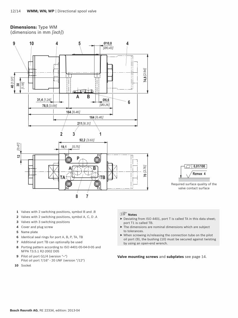
Dimensions: Type WM (dimensions in mm [inch])
Notes ▶ Deviating from ISO 4401, port T is called TA in this data sheet; port T1 is called TB.
▶ The dimensions are nominal dimensions which are subject to tolerances.
▶ When screwing in/releasing the connection tube on the pilot oil port (9), the bushing (10) must be secured against twisting by using an open-end wrench.
Required surface quality of the valve contact surface
1 Valves with 2 switching positions, symbol B and .B2 Valves with 2 switching positions, symbol A, C, D .A3 Valves with 3 switching positions4 Cover and plug screw5 Name plate6 Identical seal rings for port A, B, P, TA, TB7 Additional port TB can optionally be used8 Porting pattern according to ISO 4401-05-04-0-05 and
NFPA T3.5.1 R2-2002 D059 Pilot oil port G1/4 (version "–")
Pilot oil port 7/16" - 20 UNF (version "/12")10 Socket
Valve mounting screws and subplates see page 14.

Rzmax 4
0,01/100
� �
�� ��
���
��� ��
����
����
���
��
���
����
����
��
���
� ��
�
� �
�
���
�� �
�������
������
��
�����
�
���� ������
���� ������
������
�������
������
������
������
������
����
��
����
����
����
����
��
��
Directional spool valve | WMM; WN; WP 13/14
RE 22334, edition: 2013-04, Bosch Rexroth AG
Dimensions: Type WP (dimensions in mm [inch])
Notes ▶ Deviating from ISO 4401, port T is called TA in this data sheet; port T1 is called TB.
▶ The dimensions are nominal dimensions which are subject to tolerances.
▶ When screwing in/releasing the connection tube on the pilot oil port (9), the bushing (10) must be secured against twisting by using an open-end wrench.
Required surface quality of the valve contact surface
1 Valves with 2 switching positions, symbol B and .B2 Valves with 2 switching positions, symbol A, C, D, EA...3 Valves with 3 switching positions4 Cover and plug screw for valves with 2 switching positions,
symbol B, Y, EB...5 Name plate6 Identical seal rings for port A, B, P, TA, TB7 Additional port TB can optionally be used8 Porting pattern according to ISO 4401-05-04-0-05 and
NFPA T3.5.1 R2-2002 D059 Metric pilot oil port: G1/4
UNC pilot oil port: 7/16" - 20 UNF10 Socket
Valve mounting screws and subplates see page 14.

Bosch Rexroth AG, RE 22334, edition: 2013-04
14/14 WMM; WN; WP | Directional spool valve
Bosch Rexroth AG HydraulicsZum Eisengießer 197816 Lohr am Main, Germany Phone +49 (0) 93 52 / 18-0 [email protected] www.boschrexroth.de
© This document, as well as the data, specifications and other information set forth in it, are the exclusive property of Bosch Rexroth AG. It may not be reproduced or given to third parties without its consent.The data specified above only serve to describe the product. No statements concerning a certain condition or suitability for a certain application can be derived from our information. The information given does not release the user from the obligation of own judgment and verification. It must be remembered that our products are subject to a natural process of wear and aging.
More information
▶ Subplates Data sheet 45054 ▶ Hydraulic fluids on mineral oil basis Data sheet 90220 ▶ General product information on hydraulic products Data sheet 07008 ▶ Installation, commissioning and maintenance of industrial valves Data sheet 07300 ▶ Hydraulic valves for industrial applications Data sheet 07600-B ▶ Selection of the filters www.boschrexroth.com/filter
Dimensions
Subplates according to data sheet 45054 (separate order) G 66/01 (G3/8) 1) G 67/01 (G1/2) 1) G 534/01 (G3/4) 1)
G 66/12 (SAE-6; 9/16-18) 2) G 67/12 (SAE-8; 3/4-16) 2) G 534/12 (SAE-12; 1-1/16-12) 2)
1) For version "J4" upon request2) Upon request
Valve mounting screws (separate order)4 metric hexagon socket head cap screws ISO 4762 - M6 x 40 - 10.9-flZn-240h-L (Friction coefficient µtotal = 0.09 to 0.14); Tightening torque MA = 12.5 Nm [9.2 ft-lbs] ± 10%, material no. R913000058 or 4 hexagon socket head cap screws ISO 4762 - M6 x 40 - 10.9 (self procurement) (Friction coefficient µtotal = 0.12 to 0.17); Tightening torque MA = 15.5 Nm [11.4 ft-lbs] ± 10%
4 UNC hexagon socket head cap screws 1/4-20 UNC x 1-1/2" ASTM-A574 (Friction coefficient µtotal = 0.19 to 0.24); Tightening torque MA = 25 Nm [18.4 ft-lbs] ± 15%, (Friction coefficient µtotal = 0.12 to 0.17); Tightening torque MA = 19 Nm [14.0 ft-lbs] ± 10%, material no. R978800710
With different friction coefficients, the tightening torques are to be adjusted accordingly.

Bosch Rexroth AG HydraulicsZum Eisengießer 197816 Lohr am Main, Germany Phone +49 (0) 93 52 / 18-0 [email protected] www.boschrexroth.de
© This document, as well as the data, specifications and other information set forth in it, are the exclusive property of Bosch Rexroth AG. It may not be reproduced or given to third parties without its consent.The data specified above only serve to describe the product. No statements concerning a certain condition or suitability for a certain application can be derived from our information. The information given does not release the user from the obligation of own judgment and verification. It must be remembered that our products are subject to a natural process of wear and aging.
Directional spool valve | WMM; WN; WP 15/14
RE 22334, edition: 2013-04, Bosch Rexroth AG
Notes

Bosch Rexroth AG, RE 22334, edition: 2013-04
16/14 WMM; WN; WP | Directional spool valve
Notes