Validation of the frequency modulation technique applied ...
Upload
paul-malcolmCategory
view
81download
2description
AM Modulators: ReviewEE 179, Lecture 9, Handout #14
◮ Multiplier modulator (perhaps using variable gain amplifier)
◮ Nonlinear modulator, using square-law device
◮ Switching modulator effectively multiplies signal by square wave
Multiplying a signal by a sinusoid shifts the frequency band.
Super-heterodyning: ωmix = ωc + ωI .
Sub-heterodyning: ωmix = ωc − ωI .
EE 179, April 18, 2014 Lecture 9, Page 1
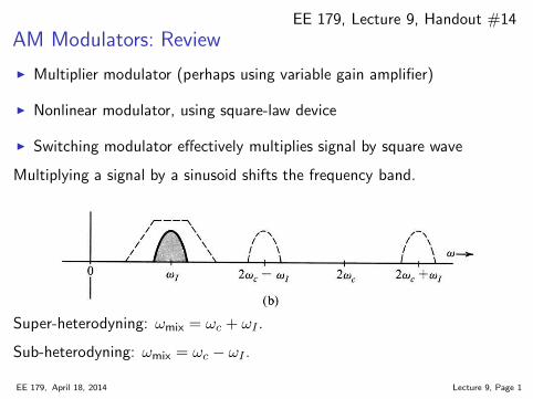
Demodulation of DSB-SC Signals
Both modulator and demodulator use a multiplier by carrier signal.
◮ Modulator uses bandpass filter
◮ Demodulator uses lowpass filter
The carrier used by the demodulator must be in phase with the transmittercarrier (taking into account transmission delay).
Such a receiver is called synchronous, coherent, homodyne.
0 0.5 1 1.5 2 2.5 3 3.5 4 4.5 5−0.5
0
0.5e2(t) = x(t) * sin(2*pi*fc*t)
0 0.5 1 1.5 2 2.5 3 3.5 4 4.5 5−0.1
−0.05
0
0.05
0.1e2(t) low−pass filtered
homo = same, dyne = power (irregular suffix)
EE 179, April 18, 2014 Lecture 9, Page 2
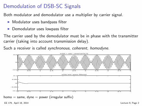
Demodulation of DSB-SC Signals (cont.)
The phase of the carrier in the received signal must be extracted.
Suppose that the signal is not ideal (frequency is shifted):
r(t) = Acm(t− t0) cos(
(ωc +∆ω)(t− t0))
= Acm(t− t0) cos(
(ωc +∆ω)t− θd)
where θd = (ωc +∆ω)t0.
The receiver has a local oscillator that must be adjusted to stay in phasewith the received signal.
A voltage-controlled oscillator (VCO) that is controlled by a phase-lockedloop (PLL) is commonly used.
If the goal is cheap receivers, then we can eliminate the PLL bytransmitting the carrier signal along with the modulated message.
ϕAM(t) = A cosωct+m(t) cos ωct = (A+m(t)) cos ωct
The tone A cosωct contains the desired carrier in correct phase.
EE 179, April 18, 2014 Lecture 9, Page 3
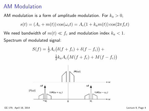
AM Modulation
AM modulation is a form of amplitude modulation. For ka > 0,
s(t) = (Ac +m(t)) cos(ωct) = Ac(1 + kam(t)) cos(2πfct)
We need bandwidth of m(t) ≪ fc and modulation index ka < 1.
Spectrum of modulated signal:
S(f) = 1
2Ac
(
δ(f + fc) + δ(f − fc))
+
1
2kaAc
(
M(f + fc) +M(f − fc))
EE 179, April 18, 2014 Lecture 9, Page 4
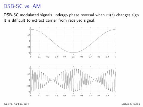
DSB-SC vs. AM
DSB-SC modulated signals undergo phase reversal when m(t) changes sign.It is difficult to extract carrier from received signal.
0 0.1 0.2 0.3 0.4 0.5 0.6 0.7 0.8 0.9 1
−1
−0.5
0
0.5
1
0 0.1 0.2 0.3 0.4 0.5 0.6 0.7 0.8 0.9 1
−1
−0.5
0
0.5
1
EE 179, April 18, 2014 Lecture 9, Page 5
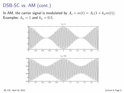
DSB-SC vs. AM (cont.)
In AM, the carrier signal is modulated by Ac +m(t) = Ac(1 + kam(t)).Examples: ka = 1 and ka = 0.5.
0 0.2 0.4 0.6 0.8 1 1.2 1.4 1.6 1.8 2−2
−1
0
1
2
ka = 1
0 0.2 0.4 0.6 0.8 1 1.2 1.4 1.6 1.8 2−1.5
−1
−0.5
0
0.5
1
1.5
ka = 0.5
EE 179, April 18, 2014 Lecture 9, Page 6
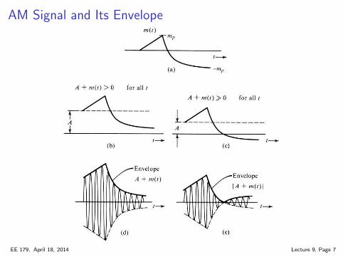
AM Signal and Its Envelope
EE 179, April 18, 2014 Lecture 9, Page 7
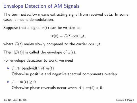
Envelope Detection of AM Signals
The term detection means extracting signal from received data. In somecases it means demodulation.
Suppose that a signal x(t) can be written as
x(t) = E(t) cos ωct ,
where E(t) varies slowly compared to the carrier cosωct.
Then |E(t)| is called the envelope of x(t).
For envelope detection to work, we need
◮ fc ≫ bandwidth of m(t)
Otherwise positive and negative spectral components overlap.
◮ A+m(t) ≥ 0
Otherwise phase reversals occur when A+m(t) < 0.
EE 179, April 18, 2014 Lecture 9, Page 8
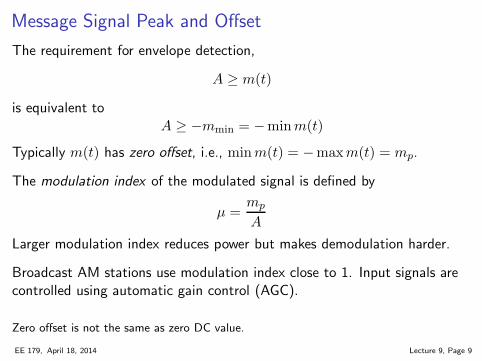
Message Signal Peak and Offset
The requirement for envelope detection,
A ≥ m(t)
is equivalent toA ≥ −mmin = −minm(t)
Typically m(t) has zero offset, i.e., minm(t) = −maxm(t) = mp.
The modulation index of the modulated signal is defined by
µ =mp
A
Larger modulation index reduces power but makes demodulation harder.
Broadcast AM stations use modulation index close to 1. Input signals arecontrolled using automatic gain control (AGC).
Zero offset is not the same as zero DC value.
EE 179, April 18, 2014 Lecture 9, Page 9
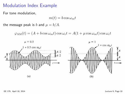
Modulation Index Example
For tone modulation,m(t) = b cosωmt
the message peak is b and µ = b/A.
ϕAM(t) = (A+ b cosωmt) cos ωct = A(1 + µ cosωmt) cosωct
EE 179, April 18, 2014 Lecture 9, Page 10
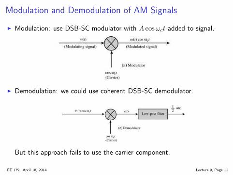
Modulation and Demodulation of AM Signals
◮ Modulation: use DSB-SC modulator with A cosωct added to signal.
◮ Demodulation: we could use coherent DSB-SC demodulator.
But this approach fails to use the carrier component.
EE 179, April 18, 2014 Lecture 9, Page 11
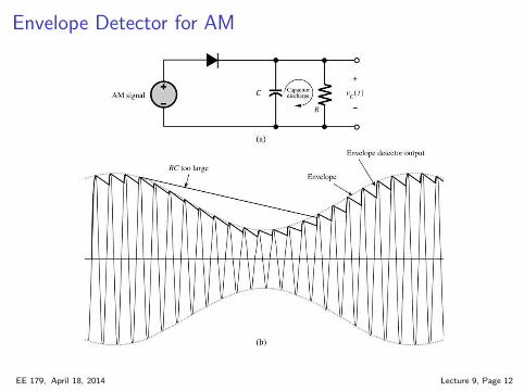
Envelope Detector for AM
EE 179, April 18, 2014 Lecture 9, Page 12
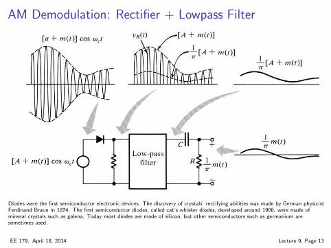
AM Demodulation: Rectifier + Lowpass Filter
Diodes were the first semiconductor electronic devices. The discovery of crystals’ rectifying abilities was made by German physicist
Ferdinand Braun in 1874. The first semiconductor diodes, called cat’s whisker diodes, developed around 1906, were made of
mineral crystals such as galena. Today most diodes are made of silicon, but other semiconductors such as germanium are
sometimes used.
EE 179, April 18, 2014 Lecture 9, Page 13
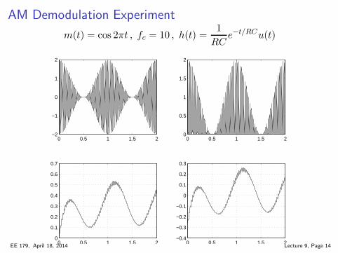
AM Demodulation Experiment
m(t) = cos 2πt , fc = 10 , h(t) =1
RCe−t/RCu(t)
0 0.5 1 1.5 2−2
−1
0
1
2
0 0.5 1 1.5 20
0.5
1
1.5
2
0 0.5 1 1.5 20
0.1
0.2
0.3
0.4
0.5
0.6
0.7
0 0.5 1 1.5 2−0.4
−0.3
−0.2
−0.1
0
0.1
0.2
0.3
EE 179, April 18, 2014 Lecture 9, Page 14
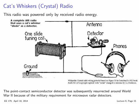
Cat’s Whiskers (Crystal) Radio
This radio was powered only by received radio energy.
The point-contact semiconductor detector was subsequently resurrected around WorldWar II because of the military requirement for microwave radar detectors.
EE 179, April 18, 2014 Lecture 9, Page 15
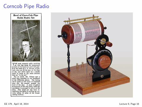
Corncob Pipe Radio
EE 179, April 18, 2014 Lecture 9, Page 16
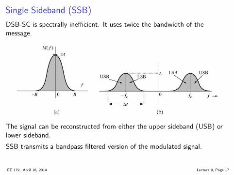
Single Sideband (SSB)
DSB-SC is spectrally inefficient. It uses twice the bandwidth of themessage.
The signal can be reconstructed from either the upper sideband (USB) orlower sideband.
SSB transmits a bandpass filtered version of the modulated signal.
EE 179, April 18, 2014 Lecture 9, Page 17
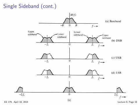
Single Sideband (cont.)
EE 179, April 18, 2014 Lecture 9, Page 18

Single Sideband (cont.)
EE 179, April 18, 2014 Lecture 9, Page 19
Single Sideband Modulation and Demodulation
◮ SSB can be transmitted using a DSB-SC modulator with a narrowerbandpass filter. For USB, center frequency is
f̃c = fc +1
2B
and cutoff frequency is B/2.
The bandfilter must roll off quickly to eliminate unwanted contributionsfrom the other sideband.
Message frequencies near 0 will be affected by the nonideal filter.
◮ SSB demodulation can use a DSB-SC demodulator with no change.
The input to the lowpass filter is different from that of DSB-SC.
EE 179, April 18, 2014 Lecture 9, Page 20

![FM- Frequency Modulation PM - Phase · PDF file7 PM and digital modulation [] [] s p where 2 is the pk-pk phase change in one symbol duration, T For Digital signals the modulation](https://static.fdocument.org/doc/165x107/5abcf34a7f8b9a567c8e631b/fm-frequency-modulation-pm-phase-pm-and-digital-modulation-s-p-where-2.jpg)