Modeling and Control of Crane Payload Lift-off and Lay … PD Trolley Hook Controller Hook...
12
© Faculty of Mechanical Engineering, Belgrade. All rights reserved FME Transactions (2016) 44, 237-248 237 Received: September 2015, Accepted: April 2016 Correspondence to: William Singhose Georgia Insitute of Technology, Woodruff School of Mechanical Engineering, USA E-mail: [email protected] doi:10.5937/fmet1603237S William Singhose Professor Georgia Institute of Technology Woodruff School of Mechanical Engineering USA Kelvin Peng Graduate Research Assistant Georgia Institute of Technology Woodruff School of Mechanical Engineering USA Anthony Garcia Graduate Research Assistant Georgia Institute of Technology Woodruff School of Mechanical Engineering USA Aldo Ferri Professor Georgia Institute of Technology Woodruff School of Mechanical Engineering USA Modeling and Control of Crane Payload Lift-off and Lay-down Operations When crane payloads are lifted off the ground, the payload may unexpectedly swing sideways. This occurs when the payload is not directly beneath the hoist. Because the hoist point is far above the payload, it is difficult for crane operators to know if the hoist cable is perfectly vertical before they start to lift the payload. Some amount of horizontal motion of the payload will always occur at lift off. If an off-centered lift results in significant horizontal motion, then it creates a hazard for the human operators, the payload, and the surrounding environment. This paper presents dynamic models of off-centered lifts and experimental verification of the theoretical predictions. The inverse problem of setting a large payload on the ground can also be challenging. For example, when laying down a long payload starting from a near-vertical orientation in the air, to a horizontal position on a flat surface, the payload can unexpectedly slide sideways. This paper presents motion-control solutions that aid operators performing challenging lay-down operations. Keywords: cranes, payload swing, crane safety. 1. INTRODUCTION Cranes are ubiquitous machines that provide essential heavy lifting capabilities for a wide range of industries. Although cranes are very useful, and are one of the most successful machines in the history of engineering, they are also dangerous machines that have several failure modes. One of the most common causes of crane- related injuries and fatalities is "side pull"[1], wherein the payload hoist cable does not hang straight down, but rather to the side. In such cases, dangerous payload sliding and swinging may occur. In a typical lift, the hook is suspended from the trolley by hoist cable(s) and attached to the payload with an arrangement of rigging cable(s). The correct procedure for lifting is to position the hoist directly over the payload’s center of mass[2]. However, accurately positioning the overhead trolley may be challenging for the crane operator because the position of the hoist is difficult to judge, especially when it is high above the payload. An off-centered lift occurs when the payload is horizontally offset from the hoist. This situation is shown in Figure 1. If the crane hoists in this configuration, then the payload may slide sideways, and swing in the air when it comes off the ground. Clearly, this presents an undesirable dynamic effect. Most crane-related research publications focus on modeling a payload swinging in the air while payload interaction with the ground is largely ignored. The most popular choice to model the swinging payload is the lumped-mass single pendulum [3]. Some prior work used more complex models to address specific situations such as varying the hoist cable length [4, 5], double pendulums [6-8], and distributed loads [9]. Trolley Hoist! Cable Rigging! Cable Payload Hook Figure 1: Off-centre crane payload hoist Barrett and Hrudey investigated lifting payloads off the ground using various hoist cable tensions[10]. However, their work focused on the dynamic forces exerted on the crane structure, rather than the motion of the payload. Modeling the contact dynamics and friction between the payload and ground is a crucial part of understanding the dynamics of off-centered lifts. A number of contact modes can exist between the payload and ground: stiction (zero relative tangential velocity between contact surfaces), sliding/slipping (non-zero relative velocity), and separation of contact (non-zero normal velocity) [11]. The choice of friction model is important for determining the mode of contact. In order to limit dangerous effects of off-center lifts, a control system can be added to the crane that aids the human operator by automatically centering the trolley over the payload. A commercial product containing such
Transcript of Modeling and Control of Crane Payload Lift-off and Lay … PD Trolley Hook Controller Hook...
© Faculty of Mechanical Engineering, Belgrade. All rights reserved FME Transactions (2016) 44, 237-248 237
Received: September 2015, Accepted: April 2016
Correspondence to: William Singhose
Georgia Insitute of Technology, Woodruff School
of Mechanical Engineering, USA
E-mail: [email protected]
doi:10.5937/fmet1603237S
William Singhose Professor
Georgia Institute of Technology Woodruff School of Mechanical Engineering
USA
Kelvin Peng
Graduate Research Assistant Georgia Institute of Technology
Woodruff School of Mechanical Engineering USA
Anthony Garcia Graduate Research Assistant
Georgia Institute of Technology Woodruff School of Mechanical Engineering
USA
Aldo Ferri
Professor Georgia Institute of Technology
Woodruff School of Mechanical Engineering USA
Modeling and Control of Crane Payload Lift-off and Lay-down Operations
When crane payloads are lifted off the ground, the payload may
unexpectedly swing sideways. This occurs when the payload is not directly
beneath the hoist. Because the hoist point is far above the payload, it is
difficult for crane operators to know if the hoist cable is perfectly vertical
before they start to lift the payload. Some amount of horizontal motion of
the payload will always occur at lift off. If an off-centered lift results in
significant horizontal motion, then it creates a hazard for the human
operators, the payload, and the surrounding environment. This paper
presents dynamic models of off-centered lifts and experimental verification
of the theoretical predictions. The inverse problem of setting a large
payload on the ground can also be challenging. For example, when laying
down a long payload starting from a near-vertical orientation in the air, to
a horizontal position on a flat surface, the payload can unexpectedly slide
sideways. This paper presents motion-control solutions that aid operators
performing challenging lay-down operations.
Keywords: cranes, payload swing, crane safety.
1. INTRODUCTION
Cranes are ubiquitous machines that provide essential
heavy lifting capabilities for a wide range of industries.
Although cranes are very useful, and are one of the most
successful machines in the history of engineering, they
are also dangerous machines that have several failure
modes. One of the most common causes of crane-
related injuries and fatalities is "side pull"[1], wherein
the payload hoist cable does not hang straight down, but
rather to the side. In such cases, dangerous payload
sliding and swinging may occur.
In a typical lift, the hook is suspended from the
trolley by hoist cable(s) and attached to the payload
with an arrangement of rigging cable(s). The correct
procedure for lifting is to position the hoist directly over
the payload’s center of mass[2]. However, accurately
positioning the overhead trolley may be challenging for
the crane operator because the position of the hoist is
difficult to judge, especially when it is high above the
payload.
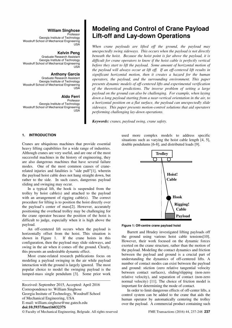
An off-centered lift occurs when the payload is
horizontally offset from the hoist. This situation is
shown in Figure 1. If the crane hoists in this
configuration, then the payload may slide sideways, and
swing in the air when it comes off the ground. Clearly,
this presents an undesirable dynamic effect.
Most crane-related research publications focus on
modeling a payload swinging in the air while payload
interaction with the ground is largely ignored. The most
popular choice to model the swinging payload is the
lumped-mass single pendulum [3]. Some prior work
used more complex models to address specific
situations such as varying the hoist cable length [4, 5],
double pendulums [6-8], and distributed loads [9].
Trolley
Hoist!
Cable
Rigging!
Cable
Payload
Hook
Figure 1: Off-centre crane payload hoist
Barrett and Hrudey investigated lifting payloads off
the ground using various hoist cable tensions[10].
However, their work focused on the dynamic forces
exerted on the crane structure, rather than the motion of
the payload. Modeling the contact dynamics and friction
between the payload and ground is a crucial part of
understanding the dynamics of off-centered lifts. A
number of contact modes can exist between the payload
and ground: stiction (zero relative tangential velocity
between contact surfaces), sliding/slipping (non-zero
relative velocity), and separation of contact (non-zero
normal velocity) [11]. The choice of friction model is
important for determining the mode of contact.
In order to limit dangerous effects of off-center lifts, a
control system can be added to the crane that aids the
human operator by automatically centering the trolley
over the payload. A commercial product containing such
238 ▪ VOL. 44, No 3, 2016 FME Transactions
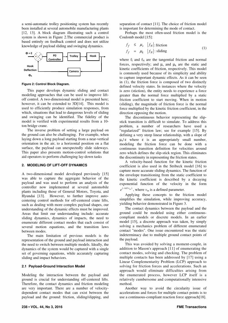
a semi-automatic trolley positioning system has recently
been installed at several automobile manufacturing plants
[12, 13]. A block diagram illustrating such a control
system is shown in Figure 2.The commercial product is
based entirely on feedback control and does not utilize
knowledge of payload sliding and swinging dynamics.
Camera
Trolley Hook PD
Controller
Hook
Deflection
ΦA
Φ = 0
Figure 2: Control Block Diagram.
This paper develops dynamic sliding and contact
modeling approaches that can be used to improve lift-
off control. A two-dimensional model is presented here;
however, it can be extended to 3D[14]. This model is
used to efficiently produce simulation responses, from
which, situations that lead to dangerous levels of sliding
and swinging can be identified. The fidelity of the
model is verified with experimental results from a 10-
ton bridge crane.
The inverse problem of setting a large payload on
the ground can also be challenging. For example, when
laying down a long payload starting from a near-vertical
orientation in the air, to a horizontal position on a flat
surface, the payload can unexpectedly slide sideways.
This paper also presents motion-control solutions that
aid operators to perform challenging lay-down tasks
2. MODELING OF LIFT-OFF DYNAMICS
A two-dimensional model developed previously [15]
was able to capture the aggregate behavior of the
payload and was used to perform an analysis of the
controller now implemented at several automobile
plants including those of General Motors, Toyota, and
Hyundai [13]. However, to further improve auto-
centering control methods for off-centered crane lifts,
such as dealing with more complex payload shapes, our
understanding of the dynamic effects must be improved.
Areas that limit our understanding include: accurate
sliding dynamics, dynamics of impacts, the need to
enumerate different contact modes that each consist of
several motion equations, and the transition laws
between modes.
The main limitation of previous models is the
representation of the ground and payload interaction and
the need to switch between multiple models. Ideally, the
dynamics of the system would be captured with a single
set of governing equations, while accurately capturing
sliding and impact behaviors.
2.1 Payload-Ground Interaction Model
Modeling the interaction between the payload and
ground is crucial for understanding off-centered lifts.
Therefore, the contact dynamics and friction modeling
are very important. There are a number of velocity-
dependent contact modes that can exist between the
payload and the ground: friction, sliding/slipping, and
separation of contact [11]. The choice of friction model
is important for determining the mode of contact.
Perhaps the most often-used friction model is the
Coulomb model [15]:
: friction
: sliding
f s N
f k N
f f
f f
µ
µ
≤
= (1)
where ff and fN are the tangential friction and normal
forces, respectively; and µs and µk are the static and
kinetic coefficients of friction, respectively. This model
is commonly used because of its simplicity and ability
to capture important dynamic effects. As it can be seen
in (1), the friction force is composed of two distinctly
defined velocity states. In instances where the velocity
is zero (stiction), the entity needs to experience a force
greater than the normal force multiplied by a static
friction coefficient to start moving. When in motion
(sliding), the magnitude of friction force is the normal
force multiplied by the kinetic friction coefficient, in the
direction opposing the motion.
The discontinuous behavior representing the slip-
stick transition is difficult to simulate. To address this
problem, a number of researchers have used a
“regularized” friction law; see for example [15]. By
defining a very steep linear relationship, with a slope of
µs/ ε where ε is an appropriately small number,
modeling the friction force can be done with a
continuous transition definition for velocities around
zero which defines the slip-stick region. This eliminates
the discontinuity in representing the friction states.
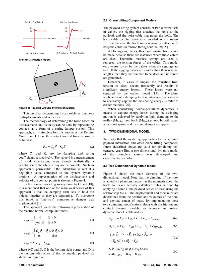
A velocity-based function for the kinetic friction
coefficient is also used in the Stribeck model [16] to
capture more accurate sliding dynamics. The function of
the envelope transitioning from the static coefficient to
the kinetic coefficient is described by a decaying
exponential function of the velocity in the form )/||( mvv
e−
, where vm is a defined parameter.
Applying these concepts to the friction model
simplifies the simulation, while improving accuracy,
yielding behavior demonstrated in Figure 3.
The contact dynamics between the payload and the
ground could be modeled using either continuous-
compliant models or discrete models. In an earlier
model [15], a discrete approach was taken, by simply
solving a mechanics problem of different enumerated
contact "modes". One issue encountered was the static
indeterminacy due to multiple ground contact points of
the payload.
This was avoided by solving a moment-couple, in
addition to Mason's approach [11] of enumerating the
contact modes, solving and checking. The problem of
multiple contacts has been addressed by [17] using a
Linear Complementarity Problem (LCP) approach to
solving for friction forces and accelerations. Such an
approach would eliminate difficulties arising from
the enumerated process, however LCP itself is a
relatively cumbersome and computationally intensive
method.
Another way to avoid the circularity issue of
accelerations and forces for multiple contact points is to
use a continuous-compliant reaction force approach[18].
FME Transactions VOL. 44, No 3, 2016 ▪ 239
Friction Coefficient Friction Coefficient
μs
μk
μs
μk
Velocity Velocity
a) Stribeck Friction b) Continuous Stribeck Friction
Friction 3: Friction Model.
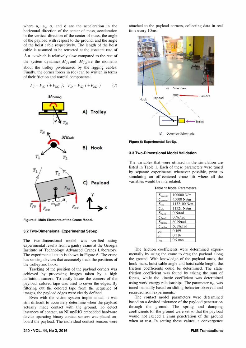
Figure 4: Payload-Ground Interaction Model.
This involves determining forces solely as functions
of displacements and velocities.
The methodology of determining the force based on
displacements and velocity can be done by representing
contacts as a form of a spring-damper system. This
approach, in its simplest form, is known as the Kelvin-
Voigt model. Here the contact normal force is simply
defined as:
N d sF C Kδ δ= +� (2)
where Cd and Ks are the damping and spring
coefficients, respectively. The value δ is a measurement
of local indentation, even though realistically a
penetration of the objects may not be possible. Such an
approach is permissible if the indentation is kept at a
negligible value compared to the system dynamic
motions. A representation of the displacement and
velocity of the contact points is shown in Figure 4.
In the contact modeling survey done by Gilardi[18],
it is mentioned that one of the main weaknesses of this
approach is that the damping term acts to hold the
objects together as they are separating. To overcome
this issue, a "one-way" compressive damper was
implemented [19].
This approach yields the following representation of
the reaction normal compliant forces:
0 0,
0.
tNKi
s i t
FK
δ
δ δ
>=
− ≤ (3)
0, 0
0, else
d i i iNCi
CF
δ δ δ ≤ ≤=
� �
(4)
Nt NCt NKiF F F= + (5)
where i=C and D. C is the bottom right corner and D is
the bottom left corner of the rectangular payload, as
shown in Figure 4.
2.2 Crane Lifting Component Models
The payload lifting system consists of two different sets
of cables, the rigging that attaches the hook to the
payload, and the hoist cable that raises the hook. The
hoist cable can be reasonably modeled as a massless
stiff rod because the hook mass is usually sufficient to
keep the cables in tension throughout the lift[15].
As for rigging cables, this same assumption cannot
be made because there are instances where these cables
are slack. Therefore, massless springs are used to
represent the tension forces of the cables. This model
only exerts forces by the cables when the riggings are
taut. If the rigging cables are shorter than their original
lengths, then they are assumed to be slack and no forces
are generated.
However, in cases of impact, the transition from
tension to slack occurs frequently and results in
significant energy losses. These losses were not
captured by the earlier model [15]. Therefore,
application of a damping term is introduced as a means
to accurately capture the dissipating energy, similar to
earlier methods [20].
When considering double-pendulum dynamics, a
means to capture energy losses during the swinging
motion is achieved by applying light damping to the
trolley (MTrolley) and hook (MHook) pivots. In both cases,
a torsional spring and torsional damper are applied.
3. TWO-DIMENSIONAL MODEL
To verify that the modeling approaches for the ground-
payload interaction and other crane lifting component
forces described above are valid for simulating off-
centered crane lifts, a two-dimensional dynamic model
of the complete system was developed and
experimentally verified.
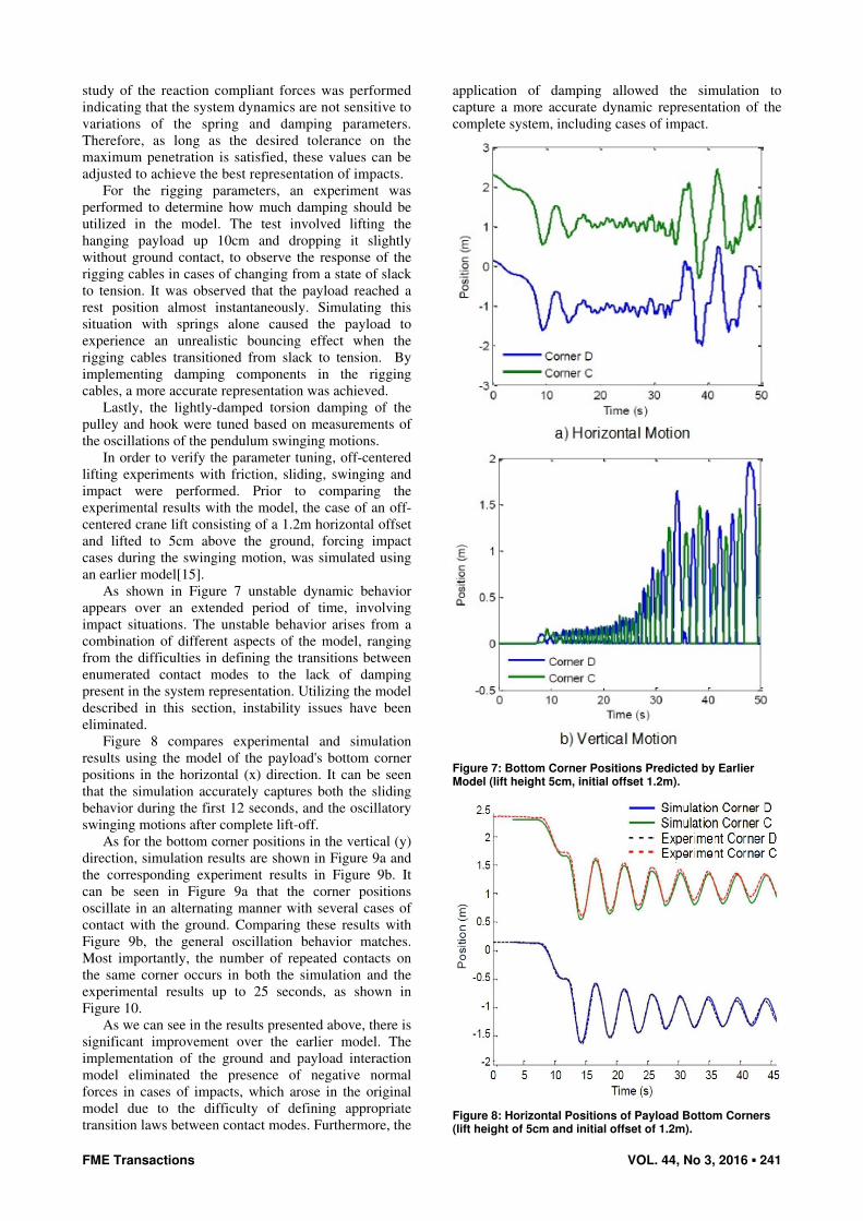
3.1 Two-Dimensional Dynamic Model
Figure 5 shows the main elements of the two-
dimensional model. Note that the damping of the hook
is actually a phantom damper, as the moments about the
hook are never actually calculated. This is done by
applying a force at the payload center of mass using the
relationship τ=Fr. The displacement and their rates are
determined from the position and velocities of the hook
and payload center of mass. By implementing these
extra damping modifications along with the friction and
contact dynamic models, an accurate and robust
dynamic model is obtained as:
MHookxxxfDfCxp FTTFFam ++++= 21 (6a)
MHookyyyNDNCyp FTTFFam ++++= 21 (6b)
1 21 2
( ) ( )
( ) ( )
p C C D D
T T
I k r F r F
r T r T
α = × + × +
+ × + ×
� � �� ���
� �� � (6c)
1 2
sin 2h h h
Trolley T T
I m Lg m LL
M M M
ϕ ϕ ϕ+ + =
= + +
��� �
(6d)
240 ▪ VOL. 44, No 3, 2016 FME Transactions
where ax, ay, α, and φ are the acceleration in the
horizontal direction of the center of mass, acceleration
in the vertical direction of the center of mass, the angle
of the payload with respect to the ground, and the angle
of the hoist cable respectively. The length of the hoist
cable is assumed to be retracted at the constant rate of
vL −=� which is relatively slow compared to the rest of
the system dynamics. 1TM and 2TM are the moments
about the trolley pivotcaused by the rigging cables.
Finally, the corner forces in (6c) can be written in terms
of their friction and normal components:
jFiFFjFiFF NDfDDNCfCC
������
+=+= ; (7)
Figure 5: Main Elements of the Crane Model.
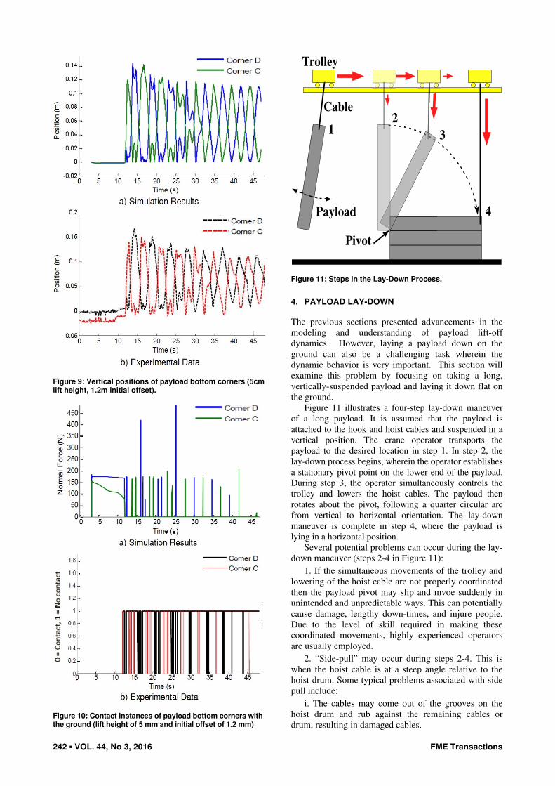
3.2 Two-Dimensional Experimental Set-up
The two-dimensional model was verified using
experimental results from a gantry crane at the Georgia
Institute of Technology Advanced Cranes Laboratory.
The experimental setup is shown in Figure 6. The crane
has sensing devices that accurately track the positions of
the trolley and hook.
Tracking of the position of the payload corners was
achieved by processing images taken by a high
definition camera. To easily locate the corners of the
payload, colored tape was used to cover the edges. By
filtering out the colored tape from the sequence of
images, the payload edges were clearly defined.
Even with the vision system implemented, it was
still difficult to accurately determine when the payload
actually made contact with the ground. To detect
instances of contact, an NI myRIO embedded hardware
device operating binary contact sensors was placed on-
board the payload. The individual contact sensors were
attached to the payload corners, collecting data in real
time every 10ms.
Figure 6: Experimental Set-Up.
3.3 Two-Dimensional Model Validation
The variables that were utilized in the simulation are
listed in Table 1. Each of these parameters were tuned
by separate experiments whenever possible, prior to
simulating an off-centered crane lift where all the
variables would be interrelated.
Table 1: Model Parameters.
Kground 100000 N/m
Cground 45000 Ns/m
Krig 1132100 N/m
Crig 11321 Ns/m
Khook 0 N/rad
Chook 0 Ns/rad
Kpulley 60 N/rad
Cpulley 60 Ns/rad
μk 0.169
μs 0.316
vm 0.9 m/s
The friction coefficients were determined experi-
mentally by using the crane to drag the payload along
the ground. With knowledge of the payload mass, the
hook mass, hoist cable angle and hoist cable length, the
friction coefficients could be determined. The static
friction coefficient was found by taking the sum of
forces, while the kinetic coefficient was determined
using work-energy relationships. The parameter υm, was
tuned manually based on sliding behavior observed and
recorded from experiments.
The contact model parameters were determined
based on a desired tolerance of the payload penetration
through the ground. The spring and damping
coefficients for the ground were set so that the payload
would not exceed a 2mm penetration of the ground
when at rest. In setting these values, a convergence
FME Transactions VOL. 44, No 3, 2016 ▪ 241
study of the reaction compliant forces was performed
indicating that the system dynamics are not sensitive to
variations of the spring and damping parameters.
Therefore, as long as the desired tolerance on the
maximum penetration is satisfied, these values can be
adjusted to achieve the best representation of impacts.
For the rigging parameters, an experiment was
performed to determine how much damping should be
utilized in the model. The test involved lifting the
hanging payload up 10cm and dropping it slightly
without ground contact, to observe the response of the
rigging cables in cases of changing from a state of slack
to tension. It was observed that the payload reached a
rest position almost instantaneously. Simulating this
situation with springs alone caused the payload to
experience an unrealistic bouncing effect when the
rigging cables transitioned from slack to tension. By
implementing damping components in the rigging
cables, a more accurate representation was achieved.
Lastly, the lightly-damped torsion damping of the
pulley and hook were tuned based on measurements of
the oscillations of the pendulum swinging motions.
In order to verify the parameter tuning, off-centered
lifting experiments with friction, sliding, swinging and
impact were performed. Prior to comparing the
experimental results with the model, the case of an off-
centered crane lift consisting of a 1.2m horizontal offset
and lifted to 5cm above the ground, forcing impact
cases during the swinging motion, was simulated using
an earlier model[15].
As shown in Figure 7 unstable dynamic behavior
appears over an extended period of time, involving
impact situations. The unstable behavior arises from a
combination of different aspects of the model, ranging
from the difficulties in defining the transitions between
enumerated contact modes to the lack of damping
present in the system representation. Utilizing the model
described in this section, instability issues have been
eliminated.
Figure 8 compares experimental and simulation
results using the model of the payload's bottom corner
positions in the horizontal (x) direction. It can be seen
that the simulation accurately captures both the sliding
behavior during the first 12 seconds, and the oscillatory
swinging motions after complete lift-off.
As for the bottom corner positions in the vertical (y)
direction, simulation results are shown in Figure 9a and
the corresponding experiment results in Figure 9b. It
can be seen in Figure 9a that the corner positions
oscillate in an alternating manner with several cases of
contact with the ground. Comparing these results with
Figure 9b, the general oscillation behavior matches.
Most importantly, the number of repeated contacts on
the same corner occurs in both the simulation and the
experimental results up to 25 seconds, as shown in
Figure 10.
As we can see in the results presented above, there is
significant improvement over the earlier model. The
implementation of the ground and payload interaction
model eliminated the presence of negative normal
forces in cases of impacts, which arose in the original
model due to the difficulty of defining appropriate
transition laws between contact modes. Furthermore, the
application of damping allowed the simulation to
capture a more accurate dynamic representation of the
complete system, including cases of impact.
Figure 7: Bottom Corner Positions Predicted by Earlier Model (lift height 5cm, initial offset 1.2m).
Figure 8: Horizontal Positions of Payload Bottom Corners (lift height of 5cm and initial offset of 1.2m).
242 ▪ VOL. 44, No 3, 2016 FME Transactions
Figure 9: Vertical positions of payload bottom corners (5cm lift height, 1.2m initial offset).
Figure 10: Contact instances of payload bottom corners with the ground (lift height of 5 mm and initial offset of 1.2 mm)
Payload
Trolley
Cable
Pivot
12
3
4
Figure 11: Steps in the Lay-Down Process.
4. PAYLOAD LAY-DOWN
The previous sections presented advancements in the
modeling and understanding of payload lift-off
dynamics. However, laying a payload down on the
ground can also be a challenging task wherein the
dynamic behavior is very important. This section will
examine this problem by focusing on taking a long,
vertically-suspended payload and laying it down flat on
the ground.
Figure 11 illustrates a four-step lay-down maneuver
of a long payload. It is assumed that the payload is
attached to the hook and hoist cables and suspended in a
vertical position. The crane operator transports the
payload to the desired location in step 1. In step 2, the
lay-down process begins, wherein the operator establishes
a stationary pivot point on the lower end of the payload.
During step 3, the operator simultaneously controls the
trolley and lowers the hoist cables. The payload then
rotates about the pivot, following a quarter circular arc
from vertical to horizontal orientation. The lay-down
maneuver is complete in step 4, where the payload is
lying in a horizontal position.
Several potential problems can occur during the lay-
down maneuver (steps 2-4 in Figure 11):
1. If the simultaneous movements of the trolley and
lowering of the hoist cable are not properly coordinated
then the payload pivot may slip and mvoe suddenly in
unintended and unpredictable ways. This can potentially
cause damage, lengthy down-times, and injure people.
Due to the level of skill required in making these
coordinated movements, highly experienced operators
are usually employed.
2. “Side-pull” may occur during steps 2-4. This is
when the hoist cable is at a steep angle relative to the
hoist drum. Some typical problems associated with side
pull include:
i. The cables may come out of the grooves on the
hoist drum and rub against the remaining cables or
drum, resulting in damaged cables.
FME Transactions VOL. 44, No 3, 2016 ▪ 243
ii. Side pull may cause unintended stress on certain
crane components.
iii. Dangerous and unpredictable payload sliding
and swinging.
The goal of the work presented in this section is to
study the dynamics of lay-down maneuvers. Then,
obtain motion-control solutions that aid operators to
avoid the problems listed above. As the process of
formulating lay-down dynamic models is similar to that
of payload lift-up, similar analysis tools can be used.
Coulomb friction is used to prescribe limit conditions
pertaining to the payload pivot.
There is very little past work concerning the lay-
down of long payloads. The closest work was by
Hermann et al., who analyzed the dynamics of
longitudinal pressure vessels and mobile cranes [21].
The focus of their paper, however, was on the erection
of these pressure vessels, rather than the lay-down
process. Traditionally, two or more mobile cranes are
employed in such operations. Erection is difficult due to
the complicated maneuvering and high levels of
coordination between the cranes. Forces and motions
during the process were modeled, which helped the
design of an innovative rigging solution that could erect
the long payload using only one crane.
One direct application of this work is in the lay-
down of 30’ (9.1m) aluminum ingots. The ingots are
lifted vertically from smelting pits, and then transported
to a storage area by a crane. The crane stores the ingots
by stacking them horizontally using a lay-down
procedure similar to that shown Figure 11. However,
one of the main problems with this procedure is that
operators can unintentionally put the crane in side-pull
situations, where the hoist cable angle is too large. This
can be a costly problem due to the frequent down-times
that are required to repair the rubbing hoist cables and
other crane components.
5. LAY-DOWN DYNAMICS
Figure 12 illustrates the dynamic model of the lay-down
process and Figure 13 is the payload’s free body
diagram. The following describes the model and its
assumptions:
1. Establishing the pivot, O, is not considered here.
This is a highly-skilled task that is more suitable for
manual operation. This is because establishing the pivot
involves collisions, sliding, and stiction between
surfaces. An automated solution would be impractical,
as it would require many expensive sensors or extensive
hardware modifications. Therefore, this research
considers steps 2-4 in Figure 11
2. The payload has a width (into/out of the page)
such that it has sufficient stability in the out of plane
direction. Therefore, out of plane movements (e.g.
buckling or trolley motions in that direction) are not
considered. The payload length is also much greater
than its thickness.
3. The pivot point, O, is the origin of the Cartesian
coordinate reference frame. The frame axes unit vectors
are i and j, as indicated in Figure 12.
4. The payload is modeled as a uniform slender
beam of length L, pinned on the lower end at the pivot
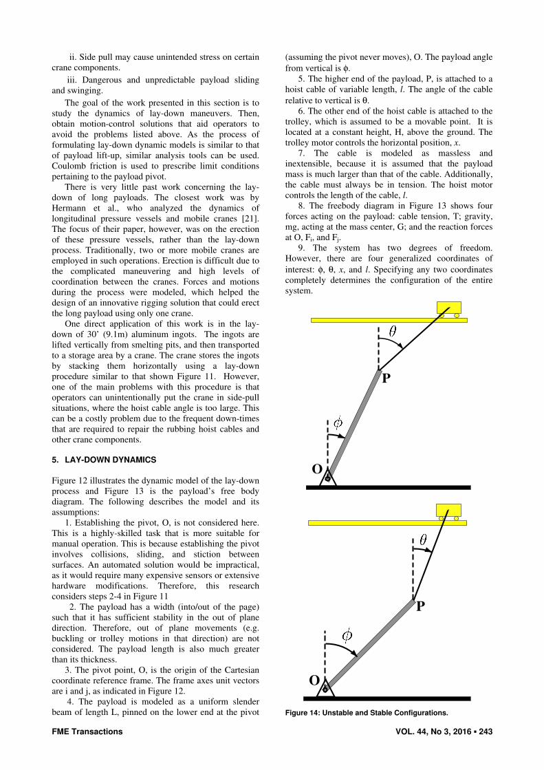
(assuming the pivot never moves), O. The payload angle
from vertical is φ.
5. The higher end of the payload, P, is attached to a
hoist cable of variable length, l. The angle of the cable
relative to vertical is θ.
6. The other end of the hoist cable is attached to the
trolley, which is assumed to be a movable point. It is
located at a constant height, H, above the ground. The
trolley motor controls the horizontal position, x.
7. The cable is modeled as massless and
inextensible, because it is assumed that the payload
mass is much larger than that of the cable. Additionally,
the cable must always be in tension. The hoist motor
controls the length of the cable, l.
8. The freebody diagram in Figure 13 shows four
forces acting on the payload: cable tension, T; gravity,
mg, acting at the mass center, G; and the reaction forces
at O, Fi, and Fj.
9. The system has two degrees of freedom.
However, there are four generalized coordinates of
interest: φ, θ, x, and l. Specifying any two coordinates
completely determines the configuration of the entire
system.
O
P
O
P
Figure 14: Unstable and Stable Configurations.
244 ▪ VOL. 44, No 3, 2016 FME Transactions
5.1 Range of Motions and Coordinate Relationships
The range of payload angles, φ, that are considered in
this investigation is from 5o (nearly vertical position,
after the operator has manually established the pivot) to
90o (horizontal position). The range of hoist cable
angles, θ, that are considered is: -90o<θ <φ.
The configuration specified by the lower bound on
θ indicates that x would be negative infinity, which is
physically impossible. The hoist cable angle upper
bound is φ, because as the top of Figure 14 shows, a
configuration with θ>φ is physically unstable. In these
cases, the payload rotates under gravity to a more
stable configuration, such that θ<φ, as shown in the
bottom of Figure 14. Note that the position of the
trolley, x, and the cable length, l, is the same in both
configurations.
The following are positional constraints in the i and j
directions that give the relationship between all four
coordinates of interest: φ, θ, x, and l.
cos cos 0
sin sin 0
L l H
L l x
φ θ
φ θ
− − =
− − = (8)
5.2 Equations of Motion
The derivation of the dynamic equations of motion for
the payload begins with the position vector from the
pivot, O, to the payload mass center, G:
( )/ sin cos2
G O
Lr i jφ φ= +
� �� (9)
The acceleration of G is found by differentiating
with respect to time:
( )
( ) ( )( )/ /
2 2cos sin sin cos2
G G O G Oa k r k k r
Li j
φ φ φ
φ φ φ φ φ φ φ φ
= − × − × − × =
= − + − −
� � �� � ��� � �
� ��� � �� �
(10)
The equations of motion can be derived in terms of
the two angles. First, the counter clockwise sum of
moments about point O is (note that φ is defined to be
positive in the clockwise direction):
( )1
cos sin sin cos sin2
OM I
TL mgL I
φ
θ φ θ φ φ φ
= −
⇒ − − = −
∑ ��
�� (11)
where 21
3I mL= is the payload moment of inertia about
O. Next, the sum of forces in the i direction is:
( )21sin cos sin
2
G
i
F i ma i
F T mLθ φ φ φ φ
⋅ = ⋅
⇒ + = −
∑� ��
�� � (12)
And the sum of forces in the j direction is:
( )21cos sin cos
2
G
j
F j ma j
F T mg mLθ φ φ φ φ
⋅ = ⋅
⇒ + − = − −
∑� ��
�� � (13)
5.3 Successful Lay-Down Conditions: Force Constraints
The primary condition for a successful lay-down
maneuver, i.e. if the motion is stable in the dynamic
sense, is that the pivot must not slip:
istatic
j
F
Fµ≤ (14)
where µstatic is the dry static coefficient of friction
between the payload and the ground. Additionally, the
payload must always maintain contact with the surface
at the pivot:
0jF ≥ (15)
and the cable must always be in tension:
(16)
Collectively, the above conditions are known as
force constraints.
5.4 Allowable Static Configurations
To determine how to best lay down the payload, it is
important to know bounds at which the system
configuration becomes unstable. The first step in this
investigation is to consider only the static case. That is,
accelerations and velocities are set to zero such that the
equations of motion are reduced to equations that
balance forces and moments in static equilibrium:
( )1
cos sin sin cos sin 02
sin 0
cos 0
i
j
TL mgL
F T
F mg
θ φ θ θ φ
θ
θ
− − =
+ =
+ − =
(17)
The above equations can be rearranged to explicitly
show T, Fi, and Fj:
( )
( )
( )( )
sin
2sin
sin sin
2sin
sin cos 2cos sin
2sin
i
j
mgT
mgF
mgF
θ
φ θ
θ φ
φ θ
φ θ φ θ
φ θ
=−
= −−
−=
−
(18)
Then, for each angle in the range of payload and
hoist cable angles being considered, it can be
determined whether the configuration is statically
allowable. The range of statically stable and allowable
configurations can then be determined.
5.4.1 Constraint on Cable Tension
By inspection, the tension is always positive, because
sinφ > 0 for the range of φ considered; and sin(φ-θ) > 0
because φ >θ at all times. Therefore, the constraint on
the cable always being in tension is always satisfied.
5.4.2 Constraint on Pivot Contact
The equation for Fj is used to determine whether the
constraint on pivot contact with the surface is satisfied.
FME Transactions VOL. 44, No 3, 2016 ▪ 245
By inspection, sin cos 2cos sin 0φ θ φ θ− ≥ needs to be
true in order to satisfy this constraint. Therefore, the
condition on θ for pivot contact is:
1arctan tan
2cθ θ φ
≤ =
(19)
5.4.3 Constraint on Pivot Slip
To determine the conditions on pivot slip, Fi is divided
by Fj to yield:
sin sin
sin cos 2cos sin
i
j
F
F
φ θ
φ θ φ θ
−=
− (20)
This is then evaluated with the constraint on pivot
slip to determine the range of hoist cable angles where
the pivot does not slip. Defining:
1 1
2 2
sinarctan ,
sin 2 cos 2 2
sinarctan ,
sin 2 cos 2 2
static
static
static
static
µ µ
µ µ
µ φ π πθ θ
φ µ φ
µ φ π πθ θ
φ µ φ
= − − < <−
= − < <+
(21)
the conditional cases on θ such that the pivot does not
slip are:
1 2 1 2
1 2 1 2
, if
OR if
µ µ µ µ
µ µ µ µ
θ θ θ θ θ
θ θ θ θ θ θ
< < <
≥ ≤ > (22)
5.5 Algorithm for Finding the Range of Allowable
Static Configurations
The allowable static configurations are found by
evaluating whether the constraints are satisfied by
iterating though the entire range of angles:
for φin the range 5o<φ< 90o
forθ in the range -90o<θ<φ if (19) AND (22) are satisfied then
The configuration is statically allowable
else
The configuration is not statically allowable
end if
end for
end for
One insight to be gained from analyzing the
constraints is that in the static case, the inequalities that
describe the allowable configurations are only dependent
on φ and µstatic. Therefore, these constraints are applicable
to all payloads regardless of size, L, and mass, µ.
5.6 Allowable Static Configurations Example
An example with the crane and payload parameters in
Table 2 is used to illustrate the process of finding
allowable static configurations. These parameters reflect
a typical aluminum ingot lay-down application.
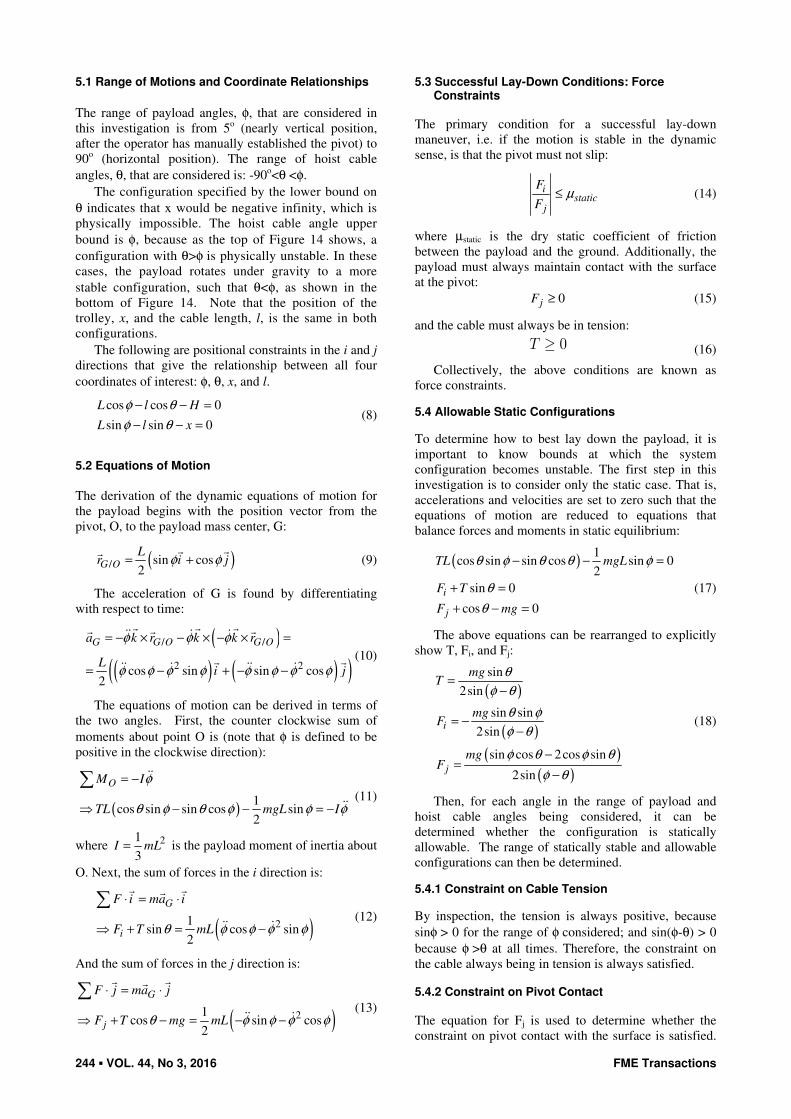
Figure 15a) shows the forces as a function of θ for
φ=10o. This is the case when the payload is close to a
vertical position near the start of lay-down. As the cable
angle approaches 0o from -90o, the cable tension
increases, but the vertical pivot force, Fj, decreases. This
makes sense, because as the cable angle becomes more
vertical, an increasing portion of the payload’s weight is
supported by the cable tension, rather than the contact at
the pivot. The critical angle at which the pivot begins to
lose contact with the surface, i.e. when Fj = 0, is
indicated on the figure as θc. In this case, the payload
will lose pivot contact when θ increases beyond a few
degrees above 0. Also, note that pivot horizontal forces,
Fi, are relatively small until θ approaches the value of φ.
Table 2: Aluminum Ingot Lay-Down Example: Crane and Payload Parameters.
Parameter Value
m 8400 kg
L 10 m
H 12 m
μstatic 0.6 (Aluminum and mild steel, dry)
a)
b)
Figure 15: Example Static Case, φφφφ = 10o.
Figure 15b) shows the ratio of horizontal to vertical
pivot force for the same range of configurations. In this
case, 1 2µ µθ θ> . The figure also shows that the force
ratio will exceed µstatic (i.e. the pivot will slip) in a
narrow range between θμ1 and θμ2. However, note that
this may be inconsequential, depending on the location
of θc in Figure 15b). For example, if θc<θµ2, then the
pivot would have already lost contact before it can slip.
246 ▪ VOL. 44, No 3, 2016 FME Transactions
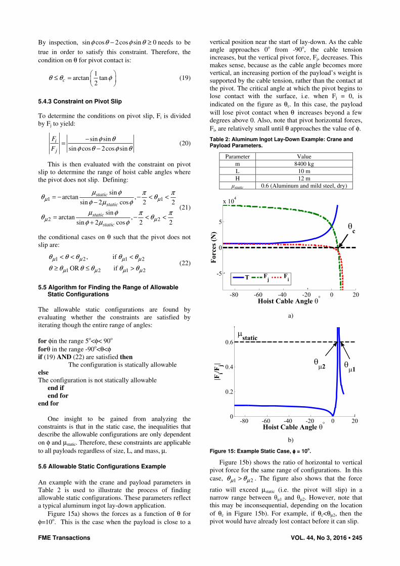
b)
Figure 16: Wooden Box Payload For Lay-Down Experiments.
5.7 Example Lay-Down Using a Bridge Crane
The methods presented above were implemented on the
10-ton bridge crane. The payload was a long wooden
box. Figure 16a) is a picture that shows the
experimental setup, when the payload is positioned
close to upright at the start of the lay-down maneuver.
Figure 16b) shows the payload in the finish position.
Note there is a hook that connects the hoist cables to the
payload. However, for the purpose of this
demonstration, the effects of the hook can be neglected.
Figure 17 shows the static and dynamic boundaries
of allowable configurations in the payload angle, φ−θ
space. (The dynamic boundaries are formed by using
additional motor constraints that limit the velocities and
accelerations of the trolley and hoist motors.) Two
features are worth noting: 1) compared to the aluminum
ingot example, the range of allowable configurations
begins to narrow starting at a lower value when φ is
approximately 35o; and 2) the dynamic boundaries are
very similar to the static boundaries. Therefore, the
static boundaries can be used to determine the lay-down
trajectory.
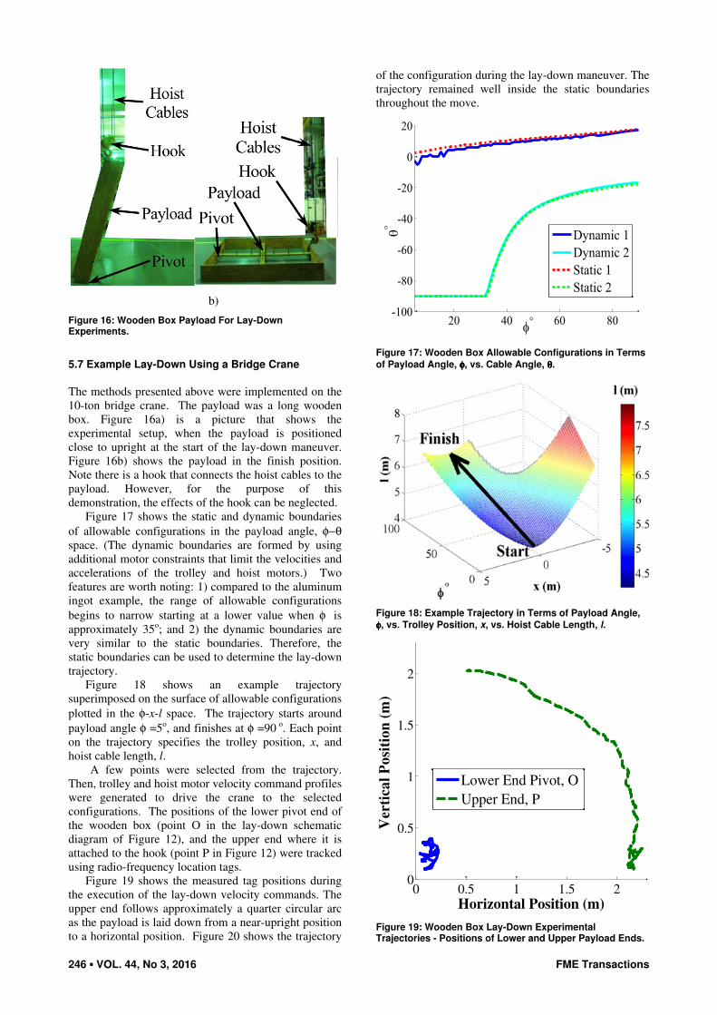
Figure 18 shows an example trajectory
superimposed on the surface of allowable configurations
plotted in the φ-x-l space. The trajectory starts around
payload angle φ =5o, and finishes at φ =90 o. Each point
on the trajectory specifies the trolley position, x, and
hoist cable length, l.
A few points were selected from the trajectory.
Then, trolley and hoist motor velocity command profiles
were generated to drive the crane to the selected
configurations. The positions of the lower pivot end of
the wooden box (point O in the lay-down schematic
diagram of Figure 12), and the upper end where it is
attached to the hook (point P in Figure 12) were tracked
using radio-frequency location tags.
Figure 19 shows the measured tag positions during
the execution of the lay-down velocity commands. The
upper end follows approximately a quarter circular arc
as the payload is laid down from a near-upright position
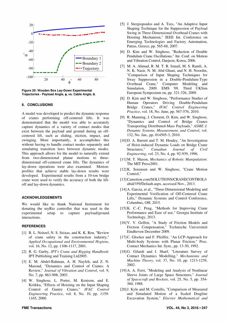
to a horizontal position. Figure 20 shows the trajectory
of the configuration during the lay-down maneuver. The
trajectory remained well inside the static boundaries
throughout the move.
Figure 17: Wooden Box Allowable Configurations in Terms
of Payload Angle, φφφφ, vs. Cable Angle, θθθθ.
Figure 18: Example Trajectory in Terms of Payload Angle,
φφφφ, vs. Trolley Position, x, vs. Hoist Cable Length, l.
0 0.5 1 1.5 20
0.5
1
1.5
2
Horizontal Position (m)
Ver
tica
l P
osi
tio
n (
m)
Lower End Pivot, O
Upper End, P
Figure 19: Wooden Box Lay-Down Experimental Trajectories - Positions of Lower and Upper Payload Ends.
FME Transactions VOL. 44, No 3, 2016 ▪ 247
Figure 20: Wooden Box Lay-Down Experimental
Trajectories - Payload Angle, φφφφ, vs. Cable Angle, θθθθ.
6. CONCLUSIONS
A model was developed to predict the dynamic response
of cranes performing off-centered lifts. It was
demonstrated that the model was able to accurately
capture dynamics of a variety of contact modes that
exist between the payload and ground during an off-
centered lift, such as sliding, stiction, impact, and
swinging. More importantly, it accomplishes this
without having to handle contact modes separately and
simulating transition laws between dynamic modes.
This approach allows for the model to naturally extend
from two-dimensional planar motions to three-
dimensional off-centered crane lifts. The dynamics of
lay-down operations were also examined. Motion-
profiles that achieve stable lay-down results were
developed. Experimental results from a 10-ton bridge
crane were used to verify the accuracy of both the lift-
off and lay-down dynamics.
ACKNOWLEDGEMENTS
We would like to thank National Instrument for
donating the myRio controller that was used in the
experimental setup to capture payload/ground
interactions.
REFERENCES
[1] R. L. Neitzel, N. S. Seixas, and K. K. Ren, "Review
of crane safety in the construction industry,"
Applied Occupational and Environmental Hygiene,
vol. 16, No. 12, pp. 1106-1117, 2001.
[2] R. G. Garby, IPT's Crane and Rigging Handbook:
IPT Publishing and Training Ltd2005.
[3] E. M. Abdel-Rahman, A. H. Nayfeh, and Z. N.
Masoud, "Dynamics and Control of Cranes: A
Review," Journal of Vibration and Control, vol. 9,
No. 7, pp. 863-908, 2003.
[4] W. Singhose, L. Porter, M. Kenison, and E.
Kriikku, "Effects of Hoisting on the Input Shaping
Control of Gantry Cranes," IFAC Control
Engineering Practice, vol. 8, No. 10, pp. 1159-
1165, 2000.
[5] J. Stergiopoulos and A. Tzes, "An Adaptive Input
Shaping Technique for the Suppression of Payload
Swing in Three-Dimensional Overhead Cranes with
Hoisting Mechanism," IEEE Int. Conference on
Emerging Technologies and Factory Automation,
Patras, Greece, pp. 565-68, 2007.
[6] D. Kim and W. Singhose, "Reduction of Double
Pendulum Crane Oscillations," Int. Conf. on Motion
and Vibration Control, Daejeon, Korea, 2006.
[7] M. A. Ahmad, R. M. T. R. Ismail, M. S. Ramli, A.
N. K. Nasir, N. M. Abd Ghani, and N. H. Noordin,
"Comparison of Input Shaping Techniques for
Sway Suppression in a Double-Pendulum-Type
Overhead Crane," Computer Modeling and
Simulation, 2009. EMS '09. Third UKSim
European Symposium on, pp. 321-326, 2009.
[8] D. Kim and W. Singhose, "Performance Studies of
Human Operators Driving Double-Pendulum
Bridge Cranes," IFAC Control Engineering
Practice, vol. 18, No. June, pp. 567-576, 2010.
[9] R. Manning, J. Clement, D. Kim, and W. Singhose,
"Dynamics and Control of Bridge Cranes
Transporting Distributed-Mass Payloads," ASME J.
Dynamic Systems, Measurement, and Control, vol.
132, No. Jan., pp. 014505-3, 2010.
[10] D. A. Barrett and T. M. Hrudey, "An Investigation
of Hoist-induced Dynamic Loads on Bridge Crane
Structures," Canadian Journal of Civil
Engineering, vol. 23, No. 4, pp. 92-939, 1996.
[11] M. T. Mason, Mechanics of Robotic Manipulation:
The MIT Press2001.
[12] K. Sorensen and W. Singhose, "Crane Motion
Control,"
[13] Camotion.com/SOLUTIONS/CRANECONTROL/t
abid/359/Default.aspx, accessed Nov., 2013.
[14] A. Garcia, et al., "Three-Dimensional Modeling and
Experimental Verification of Off-Centered Crane
Lifts," Dynamic Systems and Control Conference,
Columbus, OH, 2015.
[15] K. C.-C. Peng, "Methods for Improving Crane
Performance and Ease of use," Georgia Institute of
Technology, 2013.
[16] V. V. Geffen, "A Study of Friction Models and
Friction Compensation," Technische Universiteit
Eindhoven December 2009.
[17] C. Glocker and F. Pfeiffer, "An LCP-Approach for
Multi-body Systems with Planar Friction," Proc.
Contact Mechanics Int. Sym., pp. 13-30, 1992.
[18] G. Gilardi and I. Sharf, "Literature Survey of
Contact Dynamics Modelling," Mechanisms and
Machine Theory, vol. 37, No. 10, pp. 1213-1239,
2002.
[19] A. A. Ferri, "Modeling and Analysis of Nonlinear
Sleeve Joints of Large Space Structures," Journal
of Spacecraft and Rockets, vol. 25, No. 5, pp. 354-
360, 1988.
[20] J. Kyle and M. Costello, "Comparison of Measured
and Simulated Motion of a Scaled Dragline
Excavation System," Elsevier Mathematical and
248 ▪ VOL. 44, No 3, 2016 FME Transactions
Computer Modelling, vol. 44, No. 9-10, pp. 816-
833, 2006.
[21] U. H. Hermann, S. Hasan, M. Al-Hussein, and A.
Bouferguene, "Innovative system for off-the-
ground rotation of long objects using mobile
cranes," Journal of Construction Engineering and
Management, vol. 137, No. 7, pp. 478-485, 2011.
МОДЕЛОВАЊЕ И УПРАВЉАЊЕ
ДИЗАЛИЧНИМ ОПЕРАЦИЈАМА
ПОДИЗАЊА И СПУШТАЊА КОРИСНОГ
ТЕРЕТА
В. Сингхос, К. Пенг, А. Гарсија, А. Фери
Када дизалица подиже терет са земље може доћи до
његовог неочекиваног љуљања у страну. Ово се
дешава када терет није директно испод витла у
вертикалном правцу. Како је велико растојање
између витла и терета, руковаоци дизалицом не
могу да знају да ли је уже, пре почетка операције
дизања терета, потпуно у вертикалном положају.
При подизању терета по правилу долази до његовог
хоризонталног кретања у одређеном опсегу. Ако се
врши дизање терета које није у вертикали са витлом
долази до његовог значајног хоризонталног кретања,
настаје опасност по руковаоце дизалицом, терет и
околину. У раду се приказују динамички модели
подизања терета вертикално померених у односу на
витло као и експериментална верификација
теоријских претпоставки. Инверзни проблем
спуштања великог терета на земљу може такође да
представља изазов. На пример, када се спушта
дугачак терет у хоризонтални положај на равној
површини, полазећи од приближне вертикалне
оријентације у ваздуху, терет може неочекивано да
склизне у страну. Рад приказује решења за
управљање кретањем која могу помоћи руковаоцима
дизалицом у извођењу операције спуштања терета,
која је пуна изазова.