Model 4200-SCS - UCYModel 4200-SCS’s back panel slots, just like an SMU, and a dual-channel pulse...
20
The simple choice for complex characterization tasks A GREATER MEASURE OF CONFIDENCE www.keithley.com 4200 SCS Model 4200-SCS Semiconductor Characterization System
Transcript of Model 4200-SCS - UCYModel 4200-SCS’s back panel slots, just like an SMU, and a dual-channel pulse...
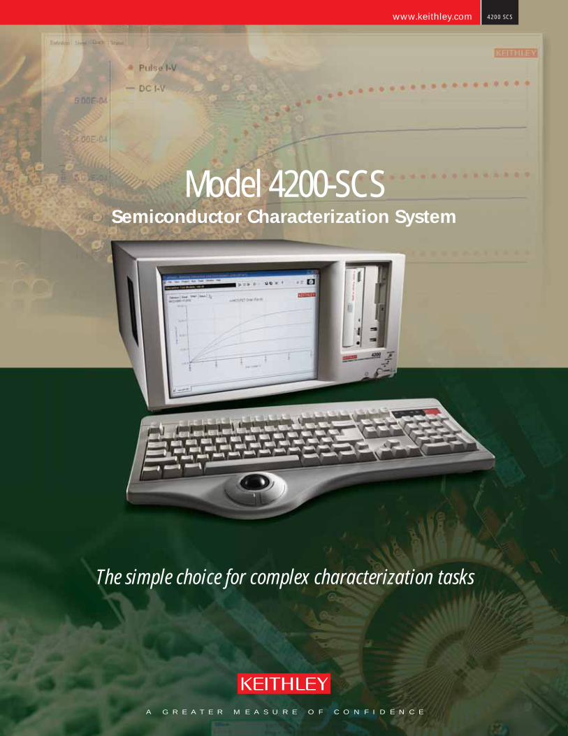
The simple choice for complex characterization tasks
A G R E A T E R M E A S U R E O F C O N F I D E N C E
www.keithley.com 4200 SCS
Model 4200-SCSSemiconductor Characterization System
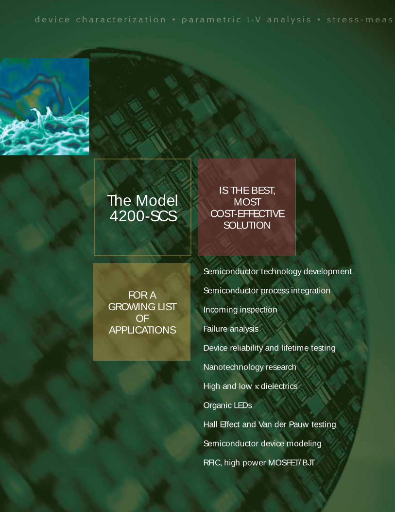
Semiconductor technology development
Semiconductor process integration
Incoming inspection
Failure analysis
Device reliability and lifetime testing
Nanotechnology research
High and low κ dielectrics
Organic LEDs
Hall Effect and Van der Pauw testing
Semiconductor device modeling
RFIC, high power MOSFET/BJT
IS THE BEST,MOST
COST-EFFECTIVE SOLUTION
FOR A GROWING LIST
OF APPLICATIONS
The Model 4200-SCS
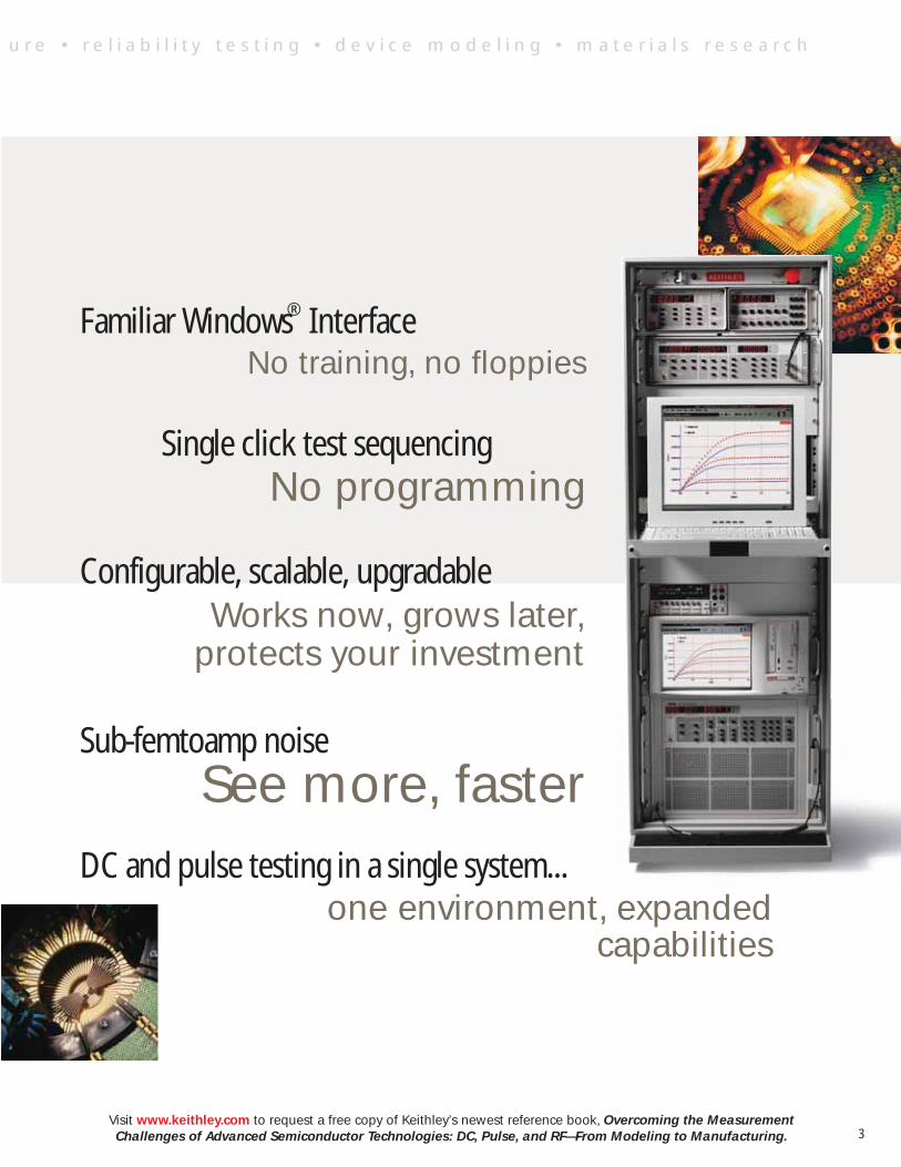
Familiar Windows ® Interface No training, no floppies
Single click test sequencing No programming
Configurable, scalable, upgradableWorks now, grows later,
protects your investment
Sub-femtoamp noise
See more, faster DC and pulse testing in a single system... one environment, expanded
capabilities
Visit www.keithley.com to request a free copy of Keithley’s newest reference book, Overcoming the Measurement Challenges of Advanced Semiconductor Technologies: DC, Pulse, and RF—From Modeling to Manufacturing.
u r e • r e l i a b i l i t y t e s t i n g • d e v i c e m o d e l i n g • m a t e r i a l s r e s e a r c h
3
KEITHLEY INTERACTIVE TEST ENVIRONMENT (KITE)
• Even infrequent users can begin testing productively right away, without programming assistance, for a lower cost of test and faster ROI.
• The flexible user interface makes it easy to change parameters on the fly and test devices interactively with just a mouse click.
• The optional Pulse I-V bundle, complete with dual-channel pulse generation and measurement, expands the Model 4200-SCS’s applications for leading-edge device and materials development, reliability, modeling, and failure analysis labs.
• Easy transition from the Agilent 4145/56. Work more productively by acquiring data, analyzing plots, and printing reports simultaneously.
• Export test settings, data, and plots to .xls, delimited text, .bmp, .jpg, or .tif file formats.
• Sample tests and projects for a variety of applications are included to simplify startup.
• Powerful stress-measure capabilities make reliability testing easier.
• Factory-supplied drivers for capacitance meters, switch matrices, pulse generators, and a variety of probers simplify building configurations for specialized applications.
• Optional drivers for leading modeling software packages let the Model 4200-SCS fit into any lab's test environment.
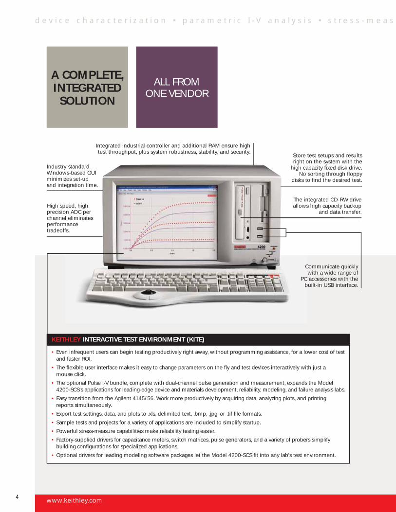
Industry-standard Windows-based GUI minimizes set-up and integration time.
Integrated industrial controller and additional RAM ensure high test throughput, plus system robustness, stability, and security.
Store test setups and results right on the system with the
high capacity fixed disk drive. No sorting through floppy
disks to find the desired test.
High speed, high precision ADC per channel eliminates performance tradeoffs.
The integrated CD-RW drive allows high capacity backup
and data transfer.
Communicate quickly with a wide range of
PC accessories with the built-in USB interface.
www.keithley.com
d e v i c e c h a r a c t e r i z a t i o n • p a r a m e t r i c I - V a n a l y s i s • s t r e s s - m e a s
ALL FROM ONE VENDOR
A COMPLETE, INTEGRATED SOLUTION
4
For more details on the Model 4200-SCS and Version 6.0 of the Keithley Test Environment Interactive (KTEI), download the Model 4200-SCS Technical Data Booklet at www.keithley.com.
Minimum pulse width of dual-channel pulse generator: 10ns (20ns period)
Maximum voltage of dual-channel pulse generator: ±20V into 50Ω
Dual-channel high speed measurement: 1.25 gigasamples/sec/channel
Bandwidth: 750MHz
Measurement resolution: 8-bit A/D
KEY AC SPECIFICATIONS
SMU Measurement Voltage 1µV/200VRange Current 0.1fA/1A
SMU Measurement Voltage 1µVResolution Current 0.1fA
SMU Measurement Voltage 100µVAccuracy Current 10fA
VMU Mode Resolution 1µV Accuracy 80µV
Ground Unit Max. Triax 2.6ACurrent Binding post 4.4A
KEY DC SPECIFICATIONS
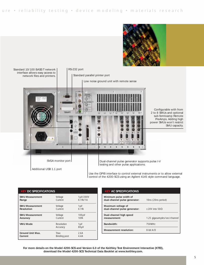
Additional USB 1.1 port
RS-232 port
Low noise ground unit with remote sense
Standard parallel printer port
Configurable with from 2 to 8 SMUs and optional
sub-femtoamp Remote PreAmps. Adding high
power SMUs won’t restrict SMU capacity.
Use the GPIB interface to control external instruments or to allow external control of the 4200-SCS using an Agilent 4145 style command language.
SVGA monitor port
Standard 10/100 BASE-T network interface allows easy access to
network files and printers.
u r e • r e l i a b i l i t y t e s t i n g • d e v i c e m o d e l i n g • m a t e r i a l s r e s e a r c h
5
Dual-channel pulse generator supports pulse I-V testing and other pulse applications.
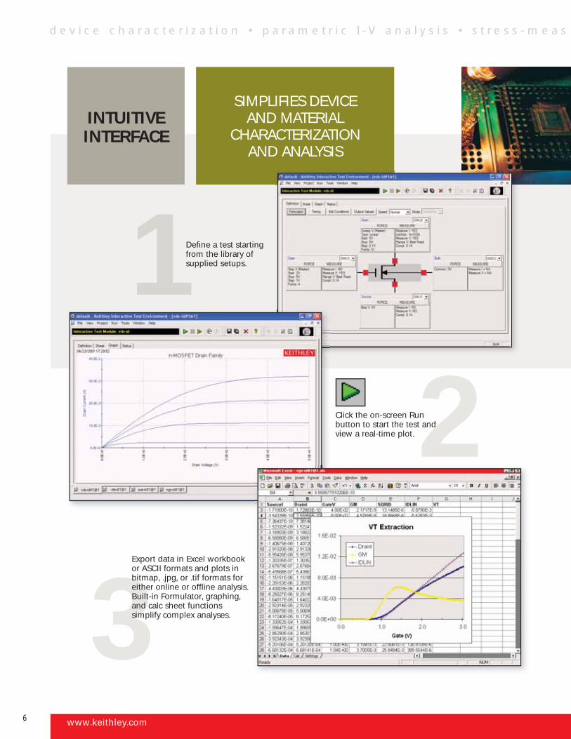
SIMPLIFIES DEVICE AND MATERIAL
CHARACTERIZATION AND ANALYSIS
1
3Export data in Excel workbook or ASCII formats and plots in bitmap, .jpg, or .tif formats for either online or offline analysis. Built-in Formulator, graphing, and calc sheet functions simplify complex analyses.
Define a test starting from the library of supplied setups.
2Click the on-screen Run button to start the test and view a real-time plot.
d e v i c e c h a r a c t e r i z a t i o n • p a r a m e t r i c I - V a n a l y s i s • s t r e s s - m e a s
www.keithley.com
INTUITIVEINTERFACE
6
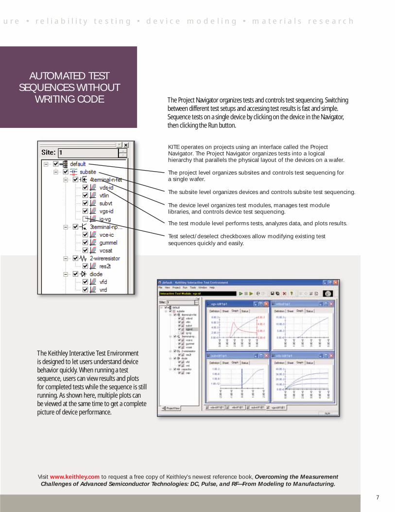
The Project Navigator organizes tests and controls test sequencing. Switching between different test setups and accessing test results is fast and simple. Sequence tests on a single device by clicking on the device in the Navigator, then clicking the Run button.
The Keithley Interactive Test Environment is designed to let users understand device behavior quickly. When running a test sequence, users can view results and plots for completed tests while the sequence is still running. As shown here, multiple plots can be viewed at the same time to get a complete picture of device performance.
KITE operates on projects using an interface called the Project Navigator. The Project Navigator organizes tests into a logical hierarchy that parallels the physical layout of the devices on a wafer.
The project level organizes subsites and controls test sequencing for a single wafer.
The subsite level organizes devices and controls subsite test sequencing.
The device level organizes test modules, manages test module libraries, and controls device test sequencing.
The test module level performs tests, analyzes data, and plots results.
Test select/deselect checkboxes allow modifying existing test sequences quickly and easily.
u r e • r e l i a b i l i t y t e s t i n g • d e v i c e m o d e l i n g • m a t e r i a l s r e s e a r c h
Visit www.keithley.com to request a free copy of Keithley’s newest reference book, Overcoming the Measurement Challenges of Advanced Semiconductor Technologies: DC, Pulse, and RF—From Modeling to Manufacturing.
AUTOMATED TEST SEQUENCES WITHOUT
WRITING CODE
7
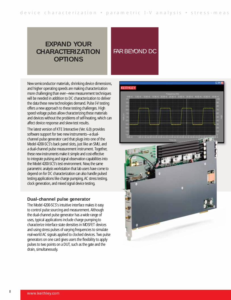
New semiconductor materials, shrinking device dimensions, and higher operating speeds are making characterization more challenging than ever—new measurement techniques will be needed in addition to DC characterization to deliver the data these new technologies demand. Pulse I-V testing offers a new approach to these testing challenges. High speed voltage pulses allow characterizing these materials and devices without the problems of self-heating, which can affect device response and skew test results.
The latest version of KTE Interactive (Ver. 6.0) provides software support for two new instruments—a dual- channel pulse generator card that plugs into one of the Model 4200-SCS’s back panel slots, just like an SMU, and a dual-channel pulse measurement instrument. Together, these new instruments make it simple and cost-effective to integrate pulsing and signal observation capabilities into the Model 4200-SCS’s test environment. Now, the same parametric analysis workstation that lab users have come to depend on for DC characterization can also handle pulsed testing applications like charge pumping, AC stress testing, clock generation, and mixed signal device testing.
Dual-channel pulse generatorThe Model 4200-SCS’s intuitive interface makes it easy to control pulse sourcing and measurement. Although the dual-channel pulse generator has a wide range of uses, typical applications include charge pumping to characterize interface state densities in MOSFET devices and using stress pulses of varying frequencies to simulate real-world AC signals applied to clocked devices. Two pulse generators on one card gives users the flexibility to apply pulses to two points on a DUT, such as the gate and the drain, simultaneously.
www.keithley.com
EXPAND YOUR CHARACTERIZATION
OPTIONSFAR BEYOND DC
d e v i c e c h a r a c t e r i z a t i o n • p a r a m e t r i c I - V a n a l y s i s • s t r e s s - m e a s
8
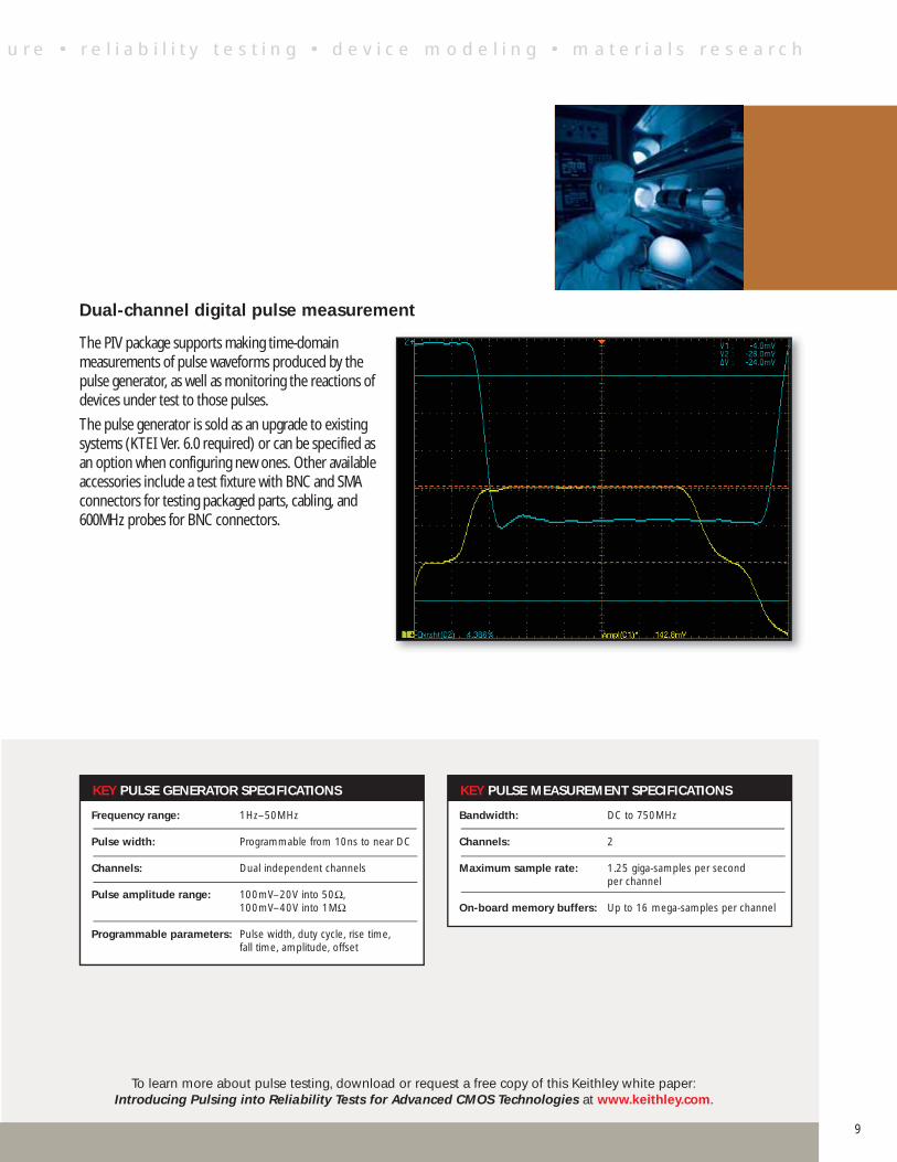
Dual-channel digital pulse measurement
The PIV package supports making time-domain measurements of pulse waveforms produced by the pulse generator, as well as monitoring the reactions of devices under test to those pulses.
The pulse generator is sold as an upgrade to existing systems (KTEI Ver. 6.0 required) or can be specified as an option when configuring new ones. Other available accessories include a test fixture with BNC and SMA connectors for testing packaged parts, cabling, and 600MHz probes for BNC connectors.
Frequency range: 1Hz–50MHz
Pulse width: Programmable from 10ns to near DC
Channels: Dual independent channels
Pulse amplitude range: 100mV–20V into 50Ω, 100mV–40V into 1MΩ
Programmable parameters: Pulse width, duty cycle, rise time, fall time, amplitude, offset
KEY PULSE GENERATOR SPECIFICATIONS
Bandwidth: DC to 750MHz
Channels: 2
Maximum sample rate: 1.25 giga-samples per second per channel
On-board memory buffers: Up to 16 mega-samples per channel
KEY PULSE MEASUREMENT SPECIFICATIONS
To learn more about pulse testing, download or request a free copy of this Keithley white paper: Introducing Pulsing into Reliability Tests for Advanced CMOS Technologies at www.keithley.com.
u r e • r e l i a b i l i t y t e s t i n g • d e v i c e m o d e l i n g • m a t e r i a l s r e s e a r c h
9
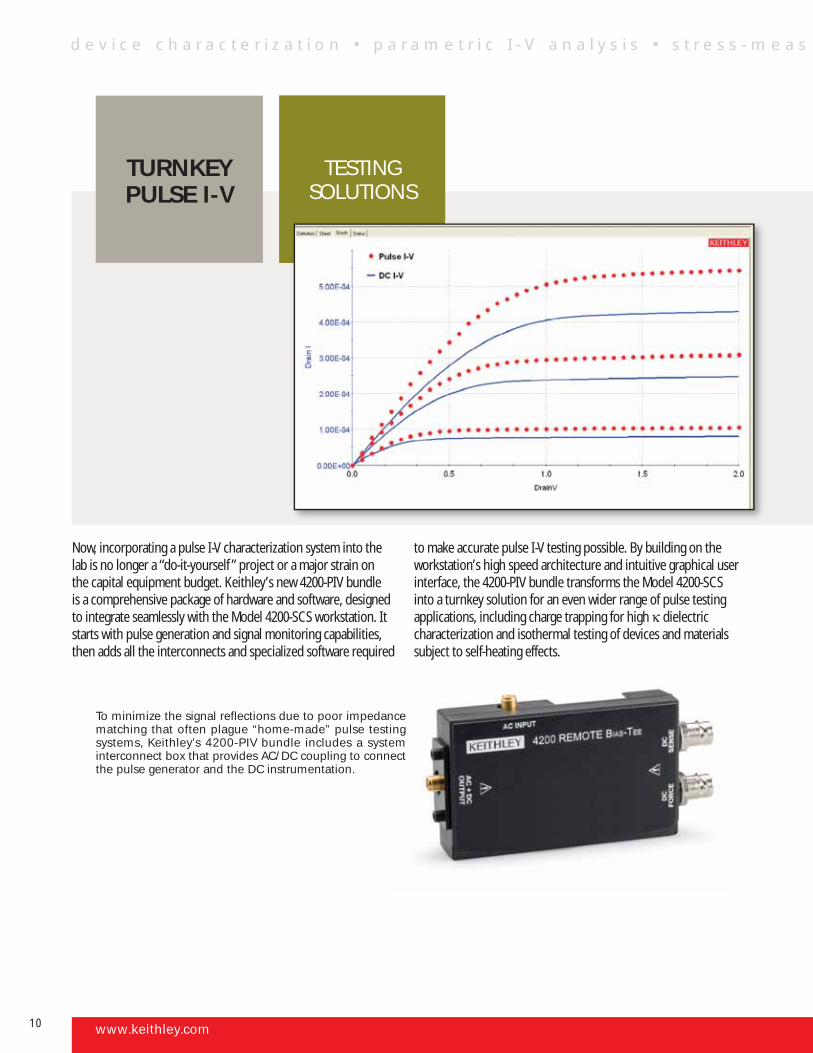
Now, incorporating a pulse I-V characterization system into the lab is no longer a “do-it-yourself ” project or a major strain on the capital equipment budget. Keithley’s new 4200-PIV bundle is a comprehensive package of hardware and software, designed to integrate seamlessly with the Model 4200-SCS workstation. It starts with pulse generation and signal monitoring capabilities, then adds all the interconnects and specialized software required
to make accurate pulse I-V testing possible. By building on the workstation’s high speed architecture and intuitive graphical user interface, the 4200-PIV bundle transforms the Model 4200-SCS into a turnkey solution for an even wider range of pulse testing applications, including charge trapping for high κ dielectric characterization and isothermal testing of devices and materials subject to self-heating effects.
To minimize the signal reflections due to poor impedance matching that often plague “home-made” pulse testing systems, Keithley’s 4200-PIV bundle includes a system interconnect box that provides AC/DC coupling to connect the pulse generator and the DC instrumentation.
www.keithley.com
TESTING SOLUTIONS
TURNKEY PULSE I-V
d e v i c e c h a r a c t e r i z a t i o n • p a r a m e t r i c I - V a n a l y s i s • s t r e s s - m e a s
10
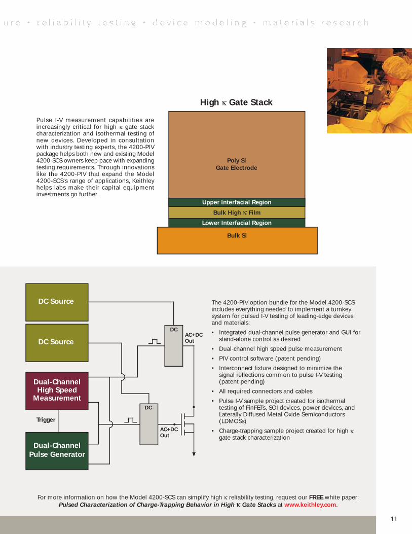
Pulse I-V measurement capabilities are increasingly critical for high κ gate stack characterization and isothermal testing of new devices. Developed in consultation with industry testing experts, the 4200-PIV package helps both new and existing Model 4200-SCS owners keep pace with expanding testing requirements. Through innovations like the 4200-PIV that expand the Model 4200-SCS’s range of applications, Keithley helps labs make their capital equipment investments go further.
The 4200-PIV option bundle for the Model 4200-SCS includes everything needed to implement a turnkey system for pulsed I-V testing of leading-edge devices and materials:
• Integrated dual-channel pulse generator and GUI for stand-alone control as desired
• Dual-channel high speed pulse measurement
• PIV control software (patent pending)
• Interconnect fixture designed to minimize the signal reflections common to pulse I-V testing (patent pending)
• All required connectors and cables
• Pulse I-V sample project created for isothermal testing of FinFETs, SOI devices, power devices, and Laterally Diffused Metal Oxide Semiconductors (LDMOSs)
• Charge-trapping sample project created for high κ gate stack characterization
For more information on how the Model 4200-SCS can simplify high κ reliability testing, request our FREE white paper: Pulsed Characterization of Charge-Trapping Behavior in High κ Gate Stacks at www.keithley.com.
Poly Si Gate Electrode
Bulk High κ Film
Lower Interfacial Region
Bulk Si
Upper Interfacial Region
High κ Gate Stack
DC Source
DC Source
Dual-Channel High Speed
Measurement
Dual-Channel Pulse Generator
Trigger
AC+DC Out
DC
DCAC+DC Out
11
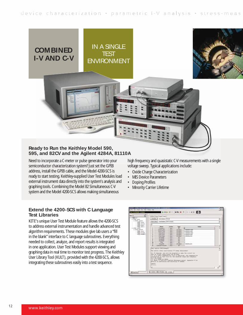
Extend the 4200-SCS with C Language Test LibrariesKITE’s unique User Test Module feature allows the 4200-SCS to address external instrumentation and handle advanced test algorithm requirements. These modules give lab users a “fill in the blank” interface to C language subroutines. Everything needed to collect, analyze, and report results is integrated in one application. User Test Modules support viewing and graphing data in real time to monitor test progress. The Keithley User Library Tool (KULT), provided with the 4200-SCS, allows integrating these subroutines easily into a test sequence.
www.keithley.com
IN A SINGLE TEST
ENVIRONMENT
COMBINED I-V AND C-V
Ready to Run the Keithley Model 590, 595, and 82CV and the Agilent 4284A, 81110A Need to incorporate a C-meter or pulse generator into your semiconductor characterization system? Just set the GPIB address, install the GPIB cable, and the Model 4200-SCS is ready to start testing. Keithley-supplied User Test Modules load external instrument data directly into the system’s analysis and graphing tools. Combining the Model 82 Simultaneous C-V system and the Model 4200-SCS allows making simultaneous
high frequency and quasistatic C-V measurements with a single voltage sweep. Typical applications include:• Oxide Charge Characterization• MIS Device Parameters• Doping Profiles• Minority Carrier Lifetime
12
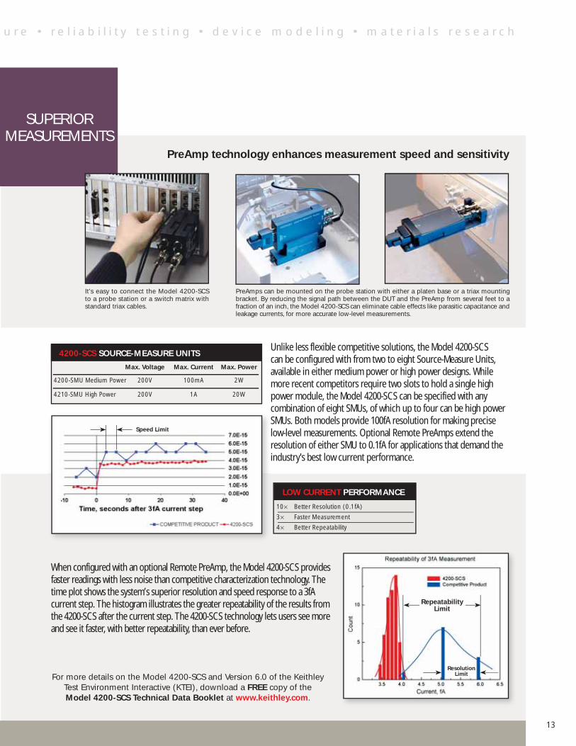
PreAmp technology enhances measurement speed and sensitivity
Unlike less flexible competitive solutions, the Model 4200-SCS can be configured with from two to eight Source-Measure Units, available in either medium power or high power designs. While more recent competitors require two slots to hold a single high power module, the Model 4200-SCS can be specified with any combination of eight SMUs, of which up to four can be high power SMUs. Both models provide 100fA resolution for making precise low-level measurements. Optional Remote PreAmps extend the resolution of either SMU to 0.1fA for applications that demand the industry's best low current performance.
When configured with an optional Remote PreAmp, the Model 4200-SCS provides faster readings with less noise than competitive characterization technology. The time plot shows the system’s superior resolution and speed response to a 3fA current step. The histogram illustrates the greater repeatability of the results from the 4200-SCS after the current step. The 4200-SCS technology lets users see more and see it faster, with better repeatability, than ever before.
LOW CURRENT PERFORMANCE
10× Better Resolution (0.1fA)
3× Faster Measurement
4× Better Repeatability
It's easy to connect the Model 4200-SCS to a probe station or a switch matrix with standard triax cables.
PreAmps can be mounted on the probe station with either a platen base or a triax mounting bracket. By reducing the signal path between the DUT and the PreAmp from several feet to a fraction of an inch, the Model 4200-SCS can eliminate cable effects like parasitic capacitance and leakage currents, for more accurate low-level measurements.
Speed Limit
4200-SCS SOURCE-MEASURE UNITS
Max. Voltage Max. Current Max. Power
4200-SMU Medium Power 200V 100mA 2W
4210-SMU High Power 200V 1A 20W
Resolution Limit
Repeatability Limit
SUPERIOR MEASUREMENTS
For more details on the Model 4200-SCS and Version 6.0 of the Keithley Test Environment Interactive (KTEI), download a FREE copy of the Model 4200-SCS Technical Data Booklet at www.keithley.com.
u r e • r e l i a b i l i t y t e s t i n g • d e v i c e m o d e l i n g • m a t e r i a l s r e s e a r c h
13
A variety of options to expand the Model 4200-SCS’s capabilities Data acquisition applications in the modeling labWe’ve given the Model 4200-SCS the flexibility to interface with Cadence’s BSIMPro and Agilent’s IC-CAP modeling applications or Silvaco’s UTMOST SPICE modeling software via the system’s built-in GPIB interface. Instrument drivers allow these packages to control the Model 4200-SCS directly, just like any piece of instrumentation linked to the modeling station.
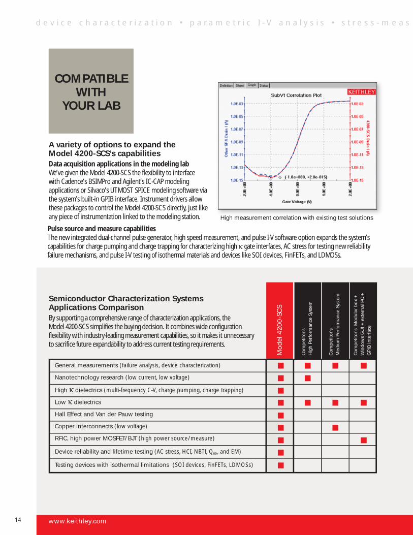
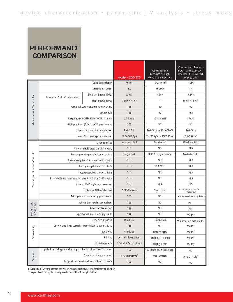
Semiconductor Characterization Systems Applications ComparisonBy supporting a comprehensive range of characterization applications, the Model 4200-SCS simplifies the buying decision. It combines wide configuration flexibility with industry-leading measurement capabilities, so it makes it unnecessary to sacrifice future expandability to address current testing requirements.
High measurement correlation with existing test solutions
General measurements (failure analysis, device characterization)
Nanotechnology research (low current, low voltage)
High κ dielectrics (multi-frequency C-V, charge pumping, charge trapping)
Low κ dielectrics
Hall Effect and Van der Pauw testing
Copper interconnects (low voltage)
RFIC, high power MOSFET/BJT (high power source/measure)
Device reliability and lifetime testing (AC stress, HCI, NBTI, QBD, and EM)
Testing devices with isothermal limitations (SOI devices, FinFETs, LDMOSs)
Mod
el 4
200-
SCS
Com
petit
or’s
H
igh
Perf
orm
ance
Sys
tem
Com
petit
or’s
Med
ium
Per
form
ance
Sys
tem
Com
petit
or’s
Mod
ular
box
+
Win
dow
s G
UI +
ext
erna
l PC
+
GPI
B in
terf
ace
COMPATIBLE WITH
YOUR LAB
Pulse source and measure capabilitiesThe new integrated dual-channel pulse generator, high speed measurement, and pulse I-V software option expands the system’s capabilities for charge pumping and charge trapping for characterizing high κ gate interfaces, AC stress for testing new reliability failure mechanisms, and pulse I-V testing of isothermal materials and devices like SOI devices, FinFETs, and LDMOSs.
www.keithley.com
d e v i c e c h a r a c t e r i z a t i o n • p a r a m e t r i c I - V a n a l y s i s • s t r e s s - m e a s
14
General Purpose
<100pAUses Model 7071 switch card
Low Current
<1pAUses Model 7072 switch card
Ultra Low Current
<100fAUses Model 7174A switch card
STANDARD SWITCH MATRIX CONFIGURATIONS
• Component ATE
• Best match to the 4200-SCS without optional PreAmps
• Excellent for remote sense applications
• Low cost, high density cables
• Expandable from 8×12 to 8×72
• Basic device characterization
• Good match to the 4200-SCS with or without optional PreAmps
• Local sense, excellent for C-V meters and pulse generators
• Standard triax cables
• Expandable from 8×12 to 8×72
• High performance device characterization
• Best match for the 4200-SCS when equipped with optional PreAmps
• Standard triax cables
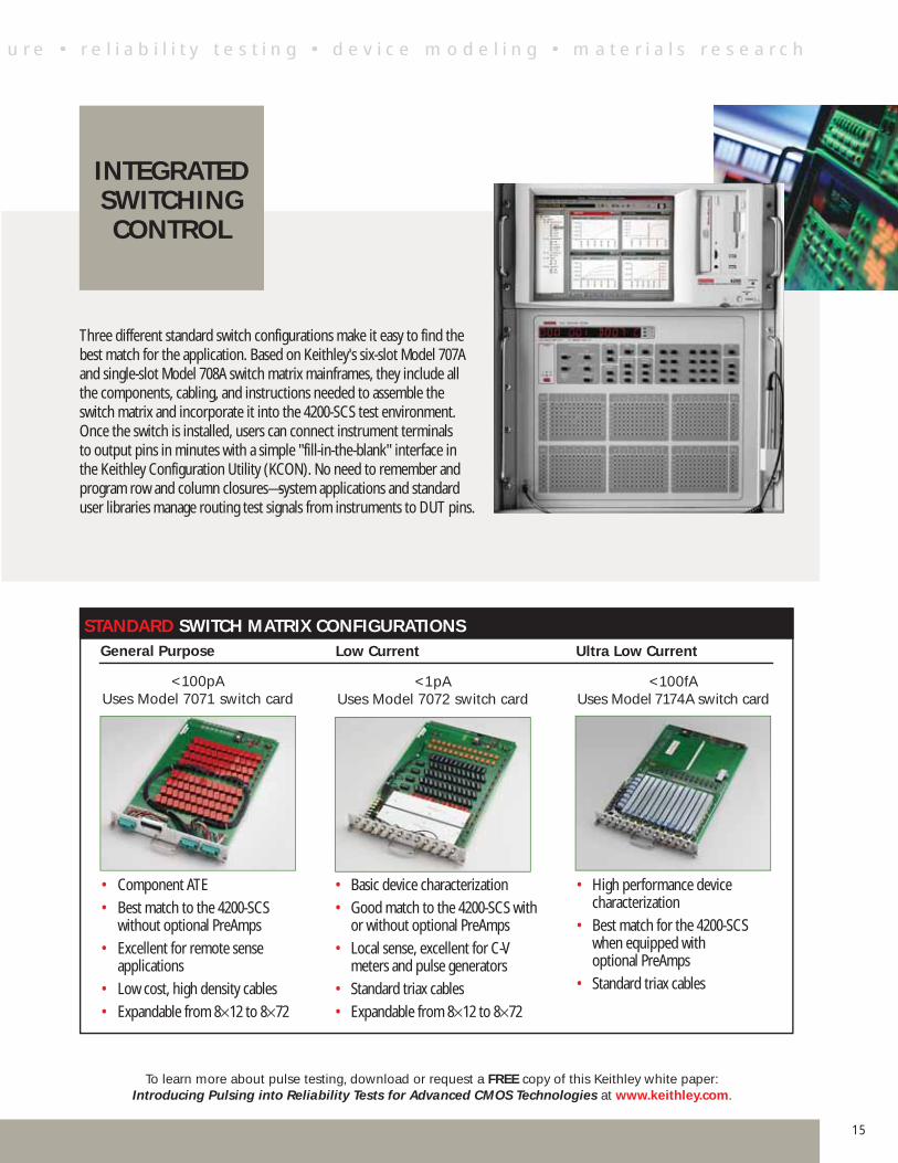
Three different standard switch configurations make it easy to find the best match for the application. Based on Keithley's six-slot Model 707A and single-slot Model 708A switch matrix mainframes, they include all the components, cabling, and instructions needed to assemble the switch matrix and incorporate it into the 4200-SCS test environment. Once the switch is installed, users can connect instrument terminals to output pins in minutes with a simple "fill-in-the-blank" interface in the Keithley Configuration Utility (KCON). No need to remember and program row and column closures—system applications and standard user libraries manage routing test signals from instruments to DUT pins.
INTEGRATED SWITCHING CONTROL
To learn more about pulse testing, download or request a FREE copy of this Keithley white paper: Introducing Pulsing into Reliability Tests for Advanced CMOS Technologies at www.keithley.com.
u r e • r e l i a b i l i t y t e s t i n g • d e v i c e m o d e l i n g • m a t e r i a l s r e s e a r c h
15
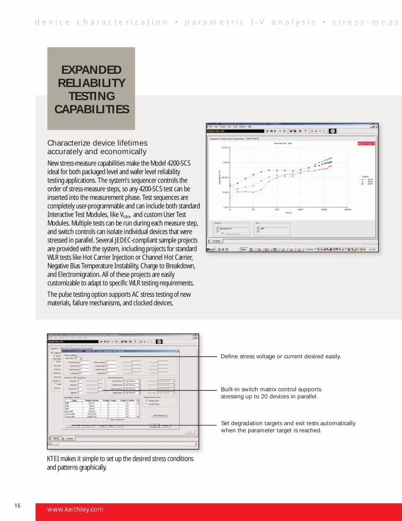
Characterize device lifetimes accurately and economicallyNew stress-measure capabilities make the Model 4200-SCS ideal for both packaged level and wafer level reliability testing applications. The system’s sequencer controls the order of stress-measure steps, so any 4200-SCS test can be inserted into the measurement phase. Test sequences are completely user-programmable and can include both standard Interactive Test Modules, like Vt-lin, and custom User Test Modules. Multiple tests can be run during each measure step, and switch controls can isolate individual devices that were stressed in parallel. Several JEDEC-compliant sample projects are provided with the system, including projects for standard WLR tests like Hot Carrier Injection or Channel Hot Carrier, Negative Bias Temperature Instability, Charge to Breakdown, and Electromigration. All of these projects are easily customizable to adapt to specific WLR testing requirements.
The pulse testing option supports AC stress testing of new materials, failure mechanisms, and clocked devices.
KTEI makes it simple to set up the desired stress conditions and patterns graphically.
Define stress voltage or current desired easily.
Set degradation targets and exit tests automatically when the parameter target is reached.
Built-in switch matrix control supports stressing up to 20 devices in parallel.
EXPANDED RELIABILITY
TESTING CAPABILITIES
www.keithley.com
d e v i c e c h a r a c t e r i z a t i o n • p a r a m e t r i c I - V a n a l y s i s • s t r e s s - m e a s
16
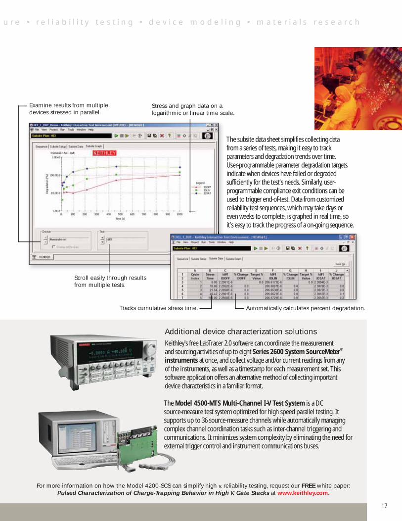
The subsite data sheet simplifies collecting data from a series of tests, making it easy to track parameters and degradation trends over time. User-programmable parameter degradation targets indicate when devices have failed or degraded sufficiently for the test’s needs. Similarly, user-programmable compliance exit conditions can be used to trigger end-of-test. Data from customized reliability test sequences, which may take days or even weeks to complete, is graphed in real time, so it’s easy to track the progress of a on-going sequence.
Stress and graph data on a logarithmic or linear time scale.
Examine results from multiple devices stressed in parallel.
Scroll easily through results from multiple tests.
Tracks cumulative stress time. Automatically calculates percent degradation.
Additional device characterization solutionsKeithley's free LabTracer 2.0 software can coordinate the measurement and sourcing activities of up to eight Series 2600 System SourceMeter® instruments at once, and collect voltage and/or current readings from any of the instruments, as well as a timestamp for each measurement set. This software application offers an alternative method of collecting important device characteristics in a familiar format.
The Model 4500-MTS Multi-Channel I-V Test System is a DC source-measure test system optimized for high speed parallel testing. It supports up to 36 source-measure channels while automatically managing complex channel coordination tasks such as inter-channel triggering and communications. It minimizes system complexity by eliminating the need for external trigger control and instrument communications buses.
For more information on how the Model 4200-SCS can simplify high κ reliability testing, request our FREE white paper: Pulsed Characterization of Charge-Trapping Behavior in High κ Gate Stacks at www.keithley.com.
u r e • r e l i a b i l i t y t e s t i n g • d e v i c e m o d e l i n g • m a t e r i a l s r e s e a r c h
17
Current resolution
Maximum current
Medium Power SMUs
High Power SMUs
Optional Low Noise Remote PreAmp
Upgradable
Required self-calibration (ACAL) interval
High precision (22-bit) ADC per channel
Lowest SMU current range/offset
Lowest SMU voltage range/offset
User interface
View multiple tests simultaneously
Test sequencing on devices or wafers
Factory-supplied C-V drivers and analysis
Factory-supplied switch drivers
Factory-supplied prober drivers
Extendable GUI can support any RS-232 or GPIB device
Agilent 4145 style command set
Hardware/GUI architecture
Microprocessor/memory per channel
Built-in Excel-style spreadsheet
Direct .xls file export
Export graphs to .bmp, .jpg, or .tif
Operating system
CD-RW and high capacity fixed disk for data archiving
Networking
Printing
Portable media
Supplied by a single vendor responsible for all service & support
Ongoing software support
Supports instrument drivers added by users
0.1fA
1A
8 MP
4 MP + 4 HP
YES
YES
24 hours
YES
1pA/10fA
200mV/80µV
Windows GUI
YES
Single click
YES
YES
YES
YES
YES
PCI/Windows
YES
YES
YES
YES
Windows
YES
Windows
Any Windows driver
CD-RW & floppy drives
YES
KTE Interactive1
YES
Mea
sure
men
t C
apab
ilitie
sD
ata
Acqu
isiti
on a
nd C
ontr
olPl
ottin
g an
d Re
port
ing
Con
nect
ivity
Supp
ort
10fA or 1fA
100mA
4 MP
—
NO
NO
30 minutes
NO
1nA/3pA or 10pA/20fA
2V/700µV or 2V/200µV
Pushbutton
NO
IBASIC programming
NO
Sort of. . .
NO
NO
YES
Front panel
NO
NO
NO
NO
Proprietary
NO
Limited NFS
Limited HP printer
Floppy drive
YES (front panel operation)
User-written
NO
10fA
1A
8 MP
0 MP + 4 HP
NO
YES
1 hour
NO
1nA/3pA
2V/700µV
Windows GUI
YES
Multiple clicks
YES
YES
YES
YES
NO
PC→Windows→USB→GPIB →
Proprietary
NO
NO
Via PC
Windows on external PC
Via PC
Via PC
Via PC
Via PC
NO
IC/V 2.1 Lite2
NO
Model 4200-SCS
Competitor’sMedium or High
Performance System
Competitor’s Modular Box + Windows GUI + External PC + 3rd Party
GPIB Solution
Maximum SMU Configuration
Low resolution only ADCs
1. Backed by a 3-year track record and with an ongoing maintenance and development schedule. 2. Requires hardware key for security, which can be difficult to replace if lost.
PERFORMANCECOMPARISON
www.keithley.com
d e v i c e c h a r a c t e r i z a t i o n • p a r a m e t r i c I - V a n a l y s i s • s t r e s s - m e a s
18
→
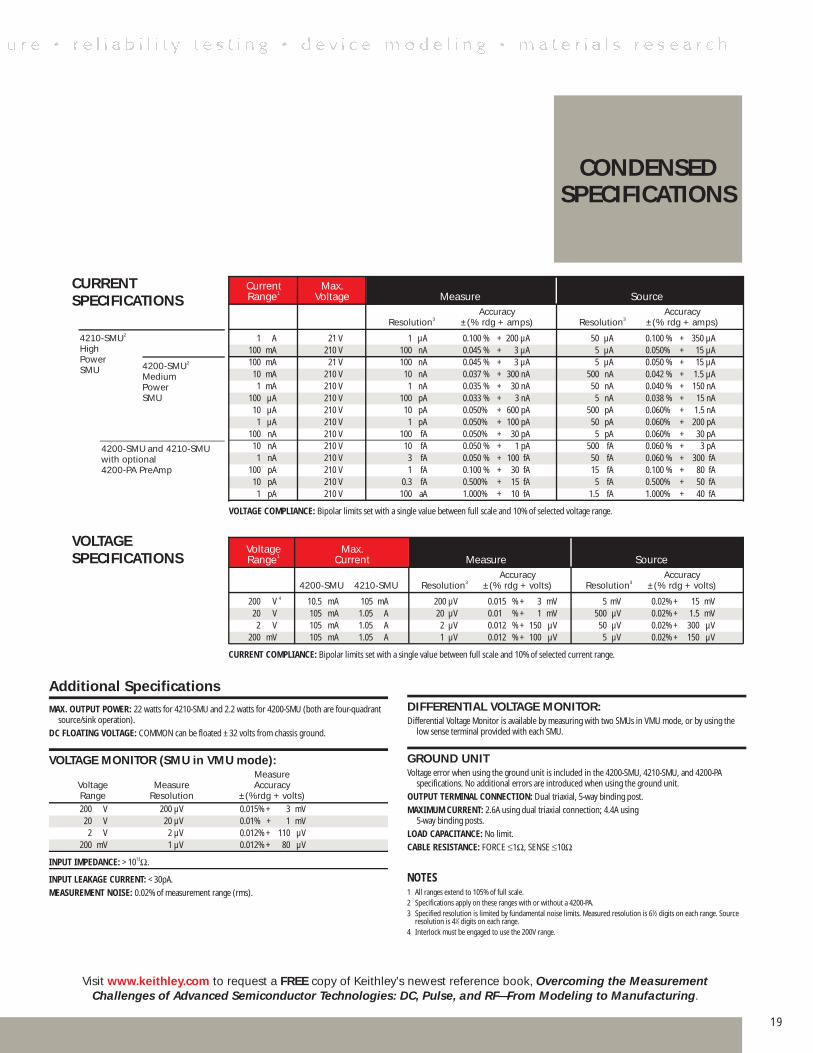
Current Max. Range1 Voltage Measure Source Accuracy Accuracy Resolution3 ±(% rdg + amps) Resolution3 ±(% rdg + amps)
1 A 21 V 1 µA 0.100 % + 200 µA 50 µA 0.100 % + 350 µA 100 mA 210 V 100 nA 0.045 % + 3 µA 5 µA 0.050% + 15 µA 100 mA 21 V 100 nA 0.045 % + 3 µA 5 µA 0.050 % + 15 µA 10 mA 210 V 10 nA 0.037 % + 300 nA 500 nA 0.042 % + 1.5 µA 1 mA 210 V 1 nA 0.035 % + 30 nA 50 nA 0.040 % + 150 nA 100 µA 210 V 100 pA 0.033 % + 3 nA 5 nA 0.038 % + 15 nA 10 µA 210 V 10 pA 0.050% + 600 pA 500 pA 0.060% + 1.5 nA 1 µA 210 V 1 pA 0.050% + 100 pA 50 pA 0.060% + 200 pA 100 nA 210 V 100 fA 0.050% + 30 pA 5 pA 0.060% + 30 pA 10 nA 210 V 10 fA 0.050 % + 1 pA 500 fA 0.060 % + 3 pA 1 nA 210 V 3 fA 0.050 % + 100 fA 50 fA 0.060 % + 300 fA 100 pA 210 V 1 fA 0.100 % + 30 fA 15 fA 0.100 % + 80 fA 10 pA 210 V 0.3 fA 0.500% + 15 fA 5 fA 0.500% + 50 fA 1 pA 210 V 100 aA 1.000% + 10 fA 1.5 fA 1.000% + 40 fA
VOLTAGE COMPLIANCE: Bipolar limits set with a single value between full scale and 10% of selected voltage range.
4200-SMU2 Medium PowerSMU
4200-SMU and 4210-SMU with optional4200-PA PreAmp
4210-SMU2 HighPowerSMU
Additional SpecificationsMAX. OUTPUT POWER: 22 watts for 4210-SMU and 2.2 watts for 4200-SMU (both are four-quadrant
source/sink operation).
DC FLOATING VOLTAGE: COMMON can be floated ±32 volts from chassis ground.
VOLTAGE MONITOR (SMU in VMU mode): Measure Voltage Measure Accuracy Range Resolution ±(%rdg + volts) 200 V 200 µV 0.015% + 3 mV 20 V 20 µV 0.01% + 1 mV 2 V 2 µV 0.012% + 110 µV 200 mV 1 µV 0.012% + 80 µV
INPUT IMPEDANCE: >1013Ω.
INPUT LEAKAGE CURRENT: <30pA.
MEASUREMENT NOISE: 0.02% of measure ment range (rms).
DIFFERENTIAL VOLTAGE MONITOR:Differential Voltage Monitor is available by measuring with two SMUs in VMU mode, or by using the
low sense terminal provided with each SMU.
GROUND UNITVoltage error when using the ground unit is included in the 4200-SMU, 4210-SMU, and 4200-PA
specifications. No additional errors are intro duced when using the ground unit.
OUTPUT TERMINAL CONNECTION: Dual triaxial, 5-way binding post.
MAXIMUM CURRENT: 2.6A using dual triaxial connection; 4.4A using 5-way binding posts.
LOAD CAPACITANCE: No limit.
CABLE RESISTANCE: FORCE ≤1Ω, SENSE ≤10Ω
NOTES1 All ranges extend to 105% of full scale.2 Specifications apply on these ranges with or without a 4200-PA.3 Specified resolution is limited by fundamental noise limits. Measured resolution is 61⁄2 digits on each range. Source
resolution is 41⁄2 digits on each range.4 Interlock must be engaged to use the 200V range.
CONDENSED SPECIFICATIONS
CURRENT SPECIFICATIONS
VOLTAGE SPECIFICATIONS
Visit www.keithley.com to request a FREE copy of Keithley’s newest reference book, Overcoming the Measurement Challenges of Advanced Semiconductor Technologies: DC, Pulse, and RF—From Modeling to Manufacturing.
Voltage Max. Range1 Current Measure Source Accuracy Accuracy 4200-SMU 4210-SMU Resolution3 ±(% rdg + volts) Resolution3 ±(% rdg + volts)
200 V 4 10.5 mA 105 mA 200 µV 0.015 % + 3 mV 5 mV 0.02% + 15 mV 20 V 105 mA 1.05 A 20 µV 0.01 % + 1 mV 500 µV 0.02% + 1.5 mV 2 V 105 mA 1.05 A 2 µV 0.012 % + 150 µV 50 µV 0.02% + 300 µV 200 mV 105 mA 1.05 A 1 µV 0.012 % + 100 µV 5 µV 0.02% + 150 µV
CURRENT COMPLIANCE: Bipolar limits set with a single value between full scale and 10% of selected current range.
19
A greater measure of confidenceWith more than a half-century of expertise in making demanding low level measurements, we offer customers a greater measure of testing confidence on the production floor, in the QA lab, and in R&D. To learn how we can help you keep pace with changing technologies, call your local Keithley sales engineer or visit our website.
Our applications engineers are here to helpConfiguring a system can be confusing. The semiconductor test experts in Keithley's Applications Engineering team are here to help you solve your toughest device characterization challenges, before and after the sale.
All the support you need For applications assistance, call us on our toll-free hotline at 1-888- KEITHLEY (534-8453) from 8:00 am to 8:00 pm ET (U.S. only). For assistance beyond those hours, send our Applications Engineering Department a facsimile (440-248-6168) or an e-mail message ([email protected]) and we'll respond as soon as possible. Applications assistance is also available via the web, with many reference materials available online, as well as convenient forms for contacting our Applications Engineers. We maintain worldwide facilities and affiliates, which offer native language support services. Visit our web site for current listings: www.keithley.com
Call us or visit www.keithley.com for FREE copies of application notes: #2239 — Gate Dielectric Capacitance-Voltage Characterization Using the Model 4200
#2240 — Evaluating Oxide Reliability
#2241 — Making Ultra-Low Current Measurements with the Low-Noise Model 4200-SCS
#2311 — DC Electrical Characterization of RF Power Transistors
#2361 — Writing Prober Drivers for the Model 4200-SCS
#2457 — Making Charge-Pumping Measurements with the Model 4200-SCS
#2475 — Four-Probe Resistivity and Hall Voltage Measurements with the Model 4200-SCS
#2481 — I-V Electrical Measurements of Nanoscale Wires and Tubes Using the Model 4200-SCS
Download your FREE copies of these white papers at www.keithley.com: • Introducing Pulsing into Reliability Tests for Advanced CMOS Technologies
• Pulsed Characterization of Charge-Trapping Behavior in High κ Gate Stacks
Call Keithley or visit www.keithley.com to receive yourFREE Model 4200-SCS Technical Data Booklet.
A G R E A T E R M E A S U R E O F C O N F I D E N C E
Keithley Instruments, Inc. Corporate Headquarters • 28775 Aurora Road • Cleveland, Ohio 44139 • 440-248-0400 • Fax: 440-248-6168 • 1-888-KEITHLEY (534-8453) • www.keithley.com
© Copyright 2005 Keithley Instruments, Inc. No. 2227Printed in U.S.A. 7057KOP
Belgium: Sint-Pieters-Leeuw • 02-363 00 40 • Fax: 02-363 00 64 • www.keithley.nl
China: Beijing • 8610-55010010 • Fax: 8610-82255018 • www.keithley.com.cn
Finland: Helsinki • 09-5306-6560 • Fax: 09-5306-6565 • www.keithley.com
France: Saint-Aubin • 01-64 53 20 20 • Fax: 01-60 11 77 26 • www.keithley.fr
Germany: Germering • 089/84 93 07-40 • Fax: 089/84 93 07-34 • www.keithley.de
Great Britain: Theale • 0118 929 7500 • Fax: 0118 929 7519 • www.keithley.co.uk
India: Bangalore: 91-80 2212 8027 • Fax: 91-80 2212 8005 • www.keithley.com
Italy: Milano • 02-48 39 16 01 • Fax: 02-48 30 22 74 • www.keithley.it
Japan: Tokyo • 81-3-5733-7555 • Fax: 81-3-5733-7556 • www.keithley.jp
Korea: Seoul • 82-2-574-7778 • Fax: 82-2-574-7838 • www.keithley.co.kr
Netherlands: Gorinchem • 0183-635333 • Fax: 0183-630821 • www.keithley.nl
Singapore: Singapore • 65-6747-9077 • Fax: 65-6747-2991 • www.keithley.com
Sweden: Solna • 08-509 04 600 • Fax: 08-655 26 10 • www.keithley.com
Taiwan: Hsinchu • 886-3-572-9077 • Fax: 886-3-572-9031 • www.keithley.com.tw
Specifications are subject to change without notice.All Keithley trademarks and trade names are the property of Keithley Instruments, Inc. All other trademarks and trade names are the property of their respective companies.
www.keithley.com4200 SCS