MODEL 230/235 - Martel Calibrators · Beta Model 230 Calibrator See back cover for Model 235...
106
MODEL 230/235 Temperature Calibrator User’s Guide
Transcript of MODEL 230/235 - Martel Calibrators · Beta Model 230 Calibrator See back cover for Model 235...
MODEL 230/235
Temperature Calibrator
User’s Guide
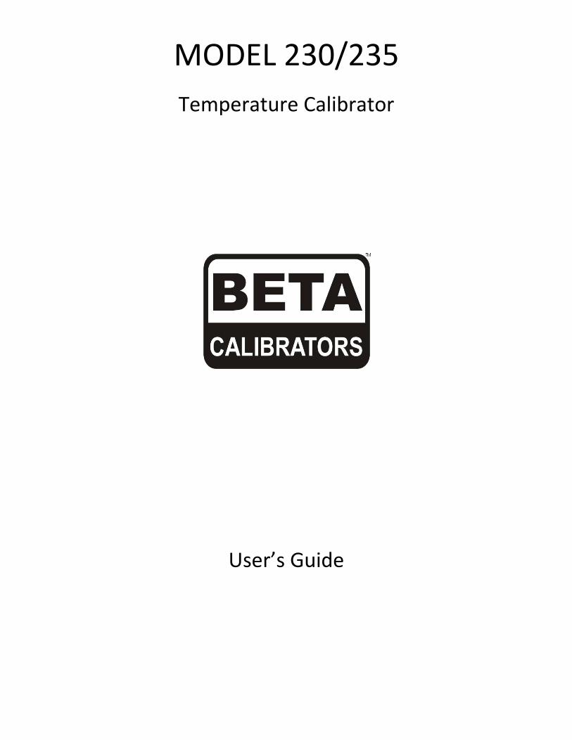
Beta Model 230 Calibrator
See back cover for Model 235
Temperature Calibrator
Model 230
ON OFF
BAT CK
CE ZERO V mV mA
7
4
1
.
8 9 TC RTD In Put
5 6 Ramp Ω Out Put
2 3 Auto -
0 Ent Opt Set Up
INPUT V/TC mA 2W 4W
3W
OUTPUT Ω/RTD V/TC
ECJ
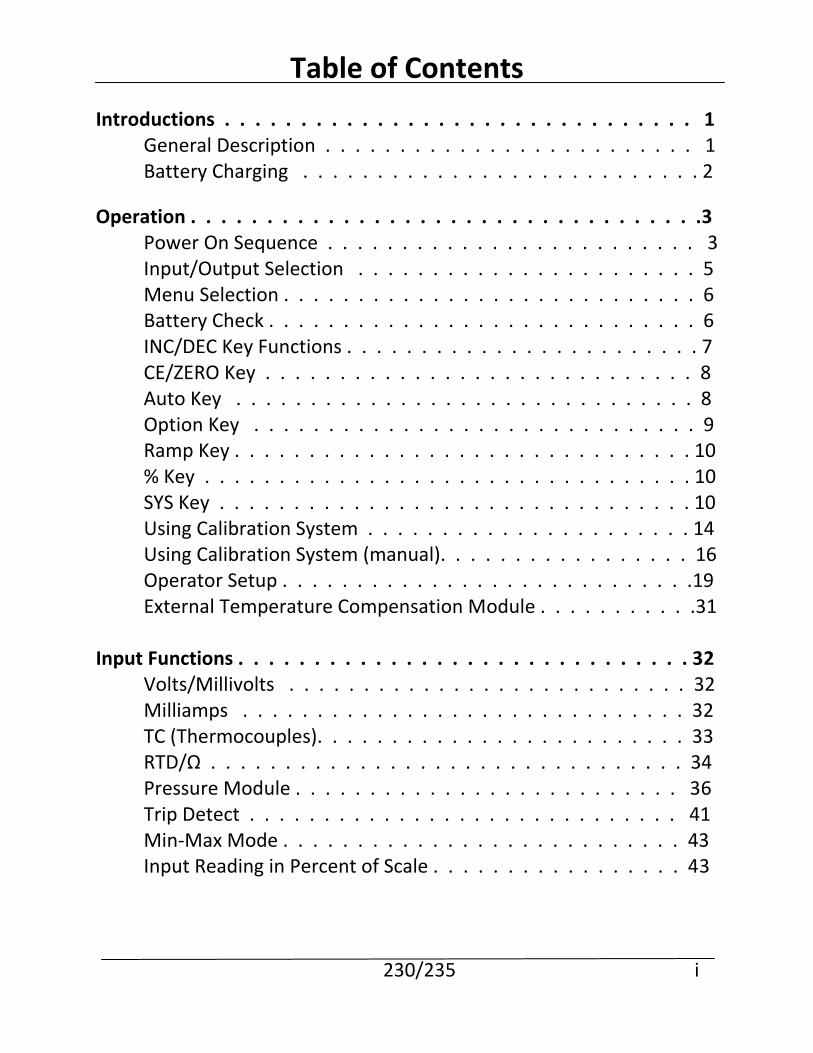
Table of Contents
Introductions . . . . . . . . . . . . . . . . . . . . . . . . . . . . . . . 1 General Description . . . . . . . . . . . . . . . . . . . . . . . . . 1 Battery Charging . . . . . . . . . . . . . . . . . . . . . . . . . . . 2
Operation . . . . . . . . . . . . . . . . . . . . . . . . . . . . . . . . . .3 Power On Sequence . . . . . . . . . . . . . . . . . . . . . . . . . 3 Input/Output Selection . . . . . . . . . . . . . . . . . . . . . . . 5 Menu Selection . . . . . . . . . . . . . . . . . . . . . . . . . . . . 6 Battery Check . . . . . . . . . . . . . . . . . . . . . . . . . . . . . 6 INC/DEC Key Functions . . . . . . . . . . . . . . . . . . . . . . . . 7 CE/ZERO Key . . . . . . . . . . . . . . . . . . . . . . . . . . . . . 8 Auto Key . . . . . . . . . . . . . . . . . . . . . . . . . . . . . . . 8 Option Key . . . . . . . . . . . . . . . . . . . . . . . . . . . . . . 9 Ramp Key . . . . . . . . . . . . . . . . . . . . . . . . . . . . . . . 10 % Key . . . . . . . . . . . . . . . . . . . . . . . . . . . . . . . . . 10 SYS Key . . . . . . . . . . . . . . . . . . . . . . . . . . . . . . . . 10 Using Calibration System . . . . . . . . . . . . . . . . . . . . . . 14 Using Calibration System (manual). . . . . . . . . . . . . . . . . 16 Operator Setup . . . . . . . . . . . . . . . . . . . . . . . . . . . .19 External Temperature Compensation Module . . . . . . . . . . .31 Input Functions . . . . . . . . . . . . . . . . . . . . . . . . . . . . . . 32 Volts/Millivolts . . . . . . . . . . . . . . . . . . . . . . . . . . . 32 Milliamps . . . . . . . . . . . . . . . . . . . . . . . . . . . . . . 32 TC (Thermocouples). . . . . . . . . . . . . . . . . . . . . . . . . 33 RTD/Ω . . . . . . . . . . . . . . . . . . . . . . . . . . . . . . . . 34 Pressure Module . . . . . . . . . . . . . . . . . . . . . . . . . . 36 Trip Detect . . . . . . . . . . . . . . . . . . . . . . . . . . . . . 41 Min-Max Mode . . . . . . . . . . . . . . . . . . . . . . . . . . . 43 Input Reading in Percent of Scale . . . . . . . . . . . . . . . . . 43
230/235 i
Output Functions . . . . . . . . . . . . . . . . . . . . . . . . . . . . 45 Volts/Millivolts . . . . . . . . . . . . . . . . . . . . . . . . . . . 45 Milliamps . . . . . . . . . . . . . . . . . . . . . . . . . . . . . . 46 Thermocouple Simulation. . . . . . . . . . . . . . . . . . . . . . 46 Ramp Function . . . . . . . . . . . . . . . . . . . . . . . . . . . 49 Auto Mode . . . . . . . . . . . . . . . . . . . . . . . . . . . . . 52 mA/V Module . . . . . . . . . . . . . . . . . . . . . . . . . . . . 54
Ohm/RTD Module (Optional) . . . . . . . . . . . . . . . . . . . 57 Loop Power Supply (Optional) . . . . . . . . . . . . . . . . . . . 57
Application Notes . . . . . . . . . . . . . . . . . . . . . . . . . . . . 59 mV to Current Converters . . . . . . . . . . . . . . . . . . . . . 59 Thermocouple 2-Wire Transmitter . . . . . . . . . . . . . . . . 60 RTD to Current 2-Wire Transmitter . . . . . . . . . . . . . . . . 62 3-Wire Platinum RTDs . . . . . . . . . . . . . . . . . . . . . . . 63
Using Ramp and Trip Detect . . . . . . . . . . . . . . . . . . . . 64 mA/V Module . . . . . . . . . . . . . . . . . . . . . . . . . . . 66 Pressure Module . . . . . . . . . . . . . . . . . . . . . . . . . . 68 Loop Powered Differential Pressure . . . . . . . . . . . . . . . . 69 Using Loop Power Supply (LPS) . . . . . . . . . . . . . . . . . . 70 Error Messages . . . . . . . . . . . . . . . . . . . . . . . . . . . . . . 71 mA/V Module Error Messages . . . . . . . . . . . . . . . . . . 73 Service Information . . . . . . . . . . . . . . . . . . . . . . . . . . . 74 Return for Calibration/Repair . . . . . . . . . . . . . . . . . . . 74 Fuse Testing . . . . . . . . . . . . . . . . . . . . . . . . . . . . 75 Fuse Replacement . . . . . . . . . . . . . . . . . . . . . . . . . . 77 mA/V Module Service Information . . . . . . . . . . . . . . . . . 79
Warranty . . . . . . . . . . . . . . . . . . . . . . . . . . . . . . . 81 ii 230/235
Specifications . . . . . . . . . . . . . . . . . . . . . . . . . . . . . . . 82 Input Specifications . . . . . . . . . . . . . . . . . . . . . . . . 82 Output Specifications . . . . . . . . . . . . . . . . . . . . . . . 85 General . . . . . . . . . . . . . . . . . . . . . . . . . . . . . . . . 88 Environmental . . . . . . . . . . . . . . . . . . . . . . . . . . . . 88 mA/V Module Specifications . . . . . . . . . . . . . . . . . . . . 89
Pressure Module Specifications . . . . . . . . . . . . . . . . . . 90 Loop Power Supply Specifications . . . . . . . . . . . . . . . . . 91 230/235 iii
Introduction
General Description The Model 230/235 Temperature Calibrators are compact, versatile, functionally styled calibrators. These units are menu driven so technicians can immediately begin using them to their fullest capabilities without extensive training. The Model 230/235 consists of four functional areas: At the top is an alphanumeric liquid crystal display (LCD) for simultaneous indication of input and output readings and operator prompting. The Model 230 uses a 2 line display while the Model 235 uses a 4 line display. The center section is a tactile membrane keyboard for operator entry. The lower section contains recessed input/output jacks for connecting the supplied test leads to the device being calibrated. There is a feature connector located at the lower end of the instrument, below the terminals, which is used to connect external modules to the calibrator to expand the calibrator’s capability. This connector is also used to calibrate the Model 230/235 calibrator and as the RS-232 interface to the Calibration System Database. Introduction 230/235 1
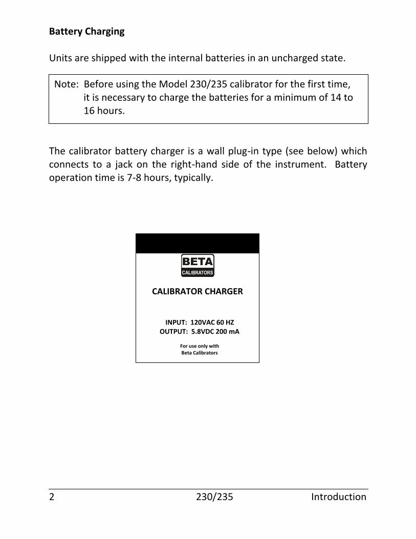
Battery Charging Units are shipped with the internal batteries in an uncharged state. The calibrator battery charger is a wall plug-in type (see below) which connects to a jack on the right-hand side of the instrument. Battery operation time is 7-8 hours, typically. 2 230/235 Introduction
Note: Before using the Model 230/235 calibrator for the first time, it is necessary to charge the batteries for a minimum of 14 to 16 hours.
CALIBRATOR CHARGER
INPUT: 120VAC 60 HZ OUTPUT: 5.8VDC 200 mA For use only with Beta Calibrators
Operation
The Model 230/235 Temperature Calibrators are user friendly and menu driven. A first time user can normally start operating the unit with little or no instruction. The following instructions are intended to provide a detailed understanding of the unit.
Power On Sequence
The calibrator is turned on or off by pressing the ON/OFF key. Each time it is turned on, a series of internal tests and calibrations are performed. The start up tests provide pass/fail tests of certain internal circuitry. If the tests determine the unit has an internal failure, a message is displayed and the unit may or may not allow further operation. A list of error messages can be found on page 71. The start up calibrations provide for dynamic recalibration of the internal calibrator support circuitry by applying the primary reference voltages to points in the circuitry and recording the readings as references for further measurements. The start up auto calibration does not in any way affect the primary calibration done at the factory or at a field metrology lab. During the time the start up tests and calibrations are being performed, certain informational displays are presented to show the status of the calibrator. The first message displayed will be: Operation 230/235 3
CAUTION: The operation of the calibrator may be impaired if a two- way radio is keyed near the unit.
BETA Calibrator Last cal 080593
This indicates the date in MMDDYY format of the last factory calibration. The example indicates the Model 230/235 was calibrated on August 5, 1993. The next display will be:
This shows the name of the owner of the calibrator. The above display shows the default setting as the calibrator is shipped. The name can be changed by selecting “owner” from the setup menu. See page 25 for details on how to change the owner’s name. The next display will be: This display will remain until the internal tests and calibrations are finished, followed by the main prompt display: On the Model 235 calibrator four line display, the time and date are displayed.
This display indicates the calibrator is operating properly and is ready to accept input or output function selections. Operation 230/235 4
property of YOUR NAME HERE
Auto Calibration in progress
Select Select Input Output
Select Select Input Output Apr 26 12:21:18
Input/Output Selection The Model 230/235 calibrator has a single set of function keys for controlling both input measurements and output simulation. The input measurement section of the calibrator is completely isolated from the output simulation section.
To select input or output functions the INPUT and OUTPUT keys are used. The calibrator is in output mode following power on.
Pressing the INPUT key places the calibrator in input mode, and pressing any function key will cause the input to begin measurements using that function.
Pressing the OUTPUT key places the calibrator in the output mode, and pressing any function key will cause the output to request the value to be simulated.
The current mode of the calibrator is indicated by the position of the blinking cursor. When the calibrator is in input mode, the cursor is on the leftmost column. When the calibrator is in output mode the cursor is on the rightmost column.
The calibrator stays in the last mode selected until the mode is changed by pressing the alternate key. For example, if you press INPUT and then V, the calibrator will begin measuring volts. If you then press MV, the input will begin measuring millivolts. If you then press OUTPUT followed by V, the output function will respond by requesting the value for the voltage.
Changing the input and output mode in no way affects the functions in operation at the time. Input and output functions operate simultaneously and without interaction. Input or output mode simply indicates whether subsequent keystrokes will be applied to the input or output function.
Operation 230/235 5
Menu Selection
The Model 230/235 calibrator has several functions that require additional information once the function has been selected. The additional information is entered by picking from a menu or list of items. For example, when selecting the Thermocouple function, you must pick the type of thermocouple and the temperature scale.
A detailed description of the menu is provided with each function that has menu choices. The following general information will provide an understanding of the operation of the menus.
The menus are composed of a title (the top line) and a list of choices (the bottom line). The title will indicate which parameter you are entering.
On the bottom line, one of the choices will be blinking. This indicates the active choice and the one that will be used if you press ENT. To select a different choice, use the INC and DEC keys. The INC key moves the choice to the right and the DEC key moves the choice to the left. If there are more choices than will fit on one line, the additional choices will scroll into view as you move the selection past the rightmost choice. When the desired choice is blinking, press ENT. If you find yourself in a function menu by mistake, pressing CE will cancel the menu and return the calibrator to the previous or idle state as appropriate.
Battery Check
The BAT CK key may be pressed at any time to display the current battery voltage for approximately 1 second before the normal display returns. The current input and output function are not disturbed by making a battery check measurement.
The battery voltage should be between 5.3 and 4.6 volts. When the Operation 230/235 6
voltage falls below 4.65 volts, a warning message is displayed is displayed approximately every minute. When the voltage falls below 4.5 volts for 1 minute, the calibrator will turn itself off to prevent damage to the batteries due to possible cell reversal.
INC/DEC key functions
The INC and DEC keys are represented on the keyboard by up and down arrow symbols respectively. They are multifunction in nature. Their use is explained in detail in each section of the manual where they are used. The following is intended to give an overall understanding of their use.
With menus:
When a menu is displayed, the INC and DEC keys act as “cursor” keys to move the highlight to the selection that you wish to make. In general, the INC key moves the selection to the right or forward, the DEC key moves the selection to the left or backward. Once you have selected the correct item, press ENT.
With Input functions:
When the calibrator is displaying an input reading and is in the input mode, i.e., the INPUT key was last pressed, the INC key causes the maximum and minimum values to be displayed. See the description of Min-Max mode for a full description.
With Output functions:
When the calibrator is outputting a variable and is in the output mode, i.e., the OUTPUT key was last pressed, the INC and DEC keys cause the output to change in one of the following manners. If ramp is active, the INC or DEC key will start the ramp in the positive or negative direction. If CalPts are enabled, the INC or DEC key will select the next or previous calibration point from the user defined list. If CalPts are not enabled, the output is increased or decreased by the user defined percent of selected scale.
Operation 230/235 7
CE/ZERO Key When the calibrator is in the output mode and you press any of the numeric keys (0-9), the keystrokes will be displayed until you press ENT and the value is accepted by the output function. If you make a keying error, the CE key is used to clear the erroneous entry and allow the correct value to be re-entered. If you press CE a second time before entering any numeric data, the keypad display mode is canceled and the calibrator returns to displaying the actual output simulation value. When the calibrator is in the input mode the CE/ZERO key acts as a zero adjustment. This is used mostly on functions such as 2-wire ohms and when using the external pressure module, but can be used on any Input function. When the key is pressed, the most recent reading is retained as the “zero point” and all subsequent readings have the zero point subtracted from them prior to being displayed. When the calibrator is displaying a menu, the CE/ZERO key acts as a CANCEL key to terminate the menu and return to the previous function or the idle state. Auto Key The AUTO key is used in conjunction with the calibration points or Ramp functions to automatically repeat the function. The time interval between the automatic repeats is determined by Setup option “Pause.” The time can range from 5 to 10,000 seconds. The Model 235 uses the AUTO key with the “System” function. The operation of the AUTO key is covered in detail with the Calibration Points and Ramp functions. Operation 230/235 8
Option Key
The OPT key is used to activate the external module that is attached to the feature connector of the Model 230/235 calibrator. When the OPT key is pressed for the first time after the calibrator is powered on, the calibrator reads the configuration and calibration data from the attached module. If no valid module is attached, or if the attached module is not supported by the software revision of the calibrator, an error message will appear. A list of error messages and their meanings can be found on page 71.
The first time the OPT key is pressed, a series of messages are displayed listing the configuration of the module.
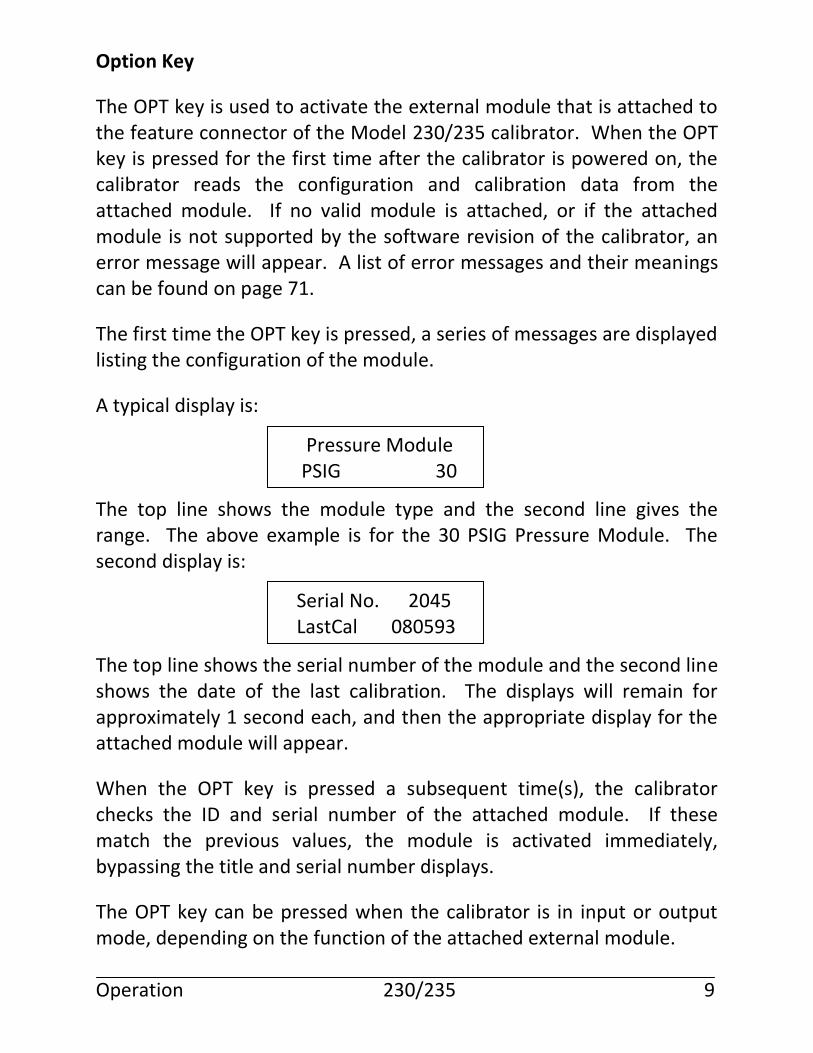
A typical display is: The top line shows the module type and the second line gives the range. The above example is for the 30 PSIG Pressure Module. The second display is: The top line shows the serial number of the module and the second line shows the date of the last calibration. The displays will remain for approximately 1 second each, and then the appropriate display for the attached module will appear.
When the OPT key is pressed a subsequent time(s), the calibrator checks the ID and serial number of the attached module. If these match the previous values, the module is activated immediately, bypassing the title and serial number displays.
The OPT key can be pressed when the calibrator is in input or output mode, depending on the function of the attached external module. Operation 230/235 9
Pressure Module PSIG 30
Serial No. 2045 LastCal 080593
If the module is not capable of operating in the mode requested, an error message will be displayed.
The operation of the Pressure Module can be found on page 36, that of the mA/V Module can be found on page 54.
Ramp Key
The RAMP key is used to activate the ramp function which is covered in the Output Functions section starting at page 54.
% Key (Model 235 Only)
The % Key allows easy access to the % Error Function. If the % ERR Function has been set up using the SETUP menus (see page 19), press the % Key to alternate between the Engineering Unit display and the % ERR display.
SYS Key (Model 235 Only)
The SYS Key allows the Model 235 Calibrator to be used with a Calibration System Database. Refer to the Calibration System Database Instruction Manual for system information. Operation of the calibrator is covered in this manual.
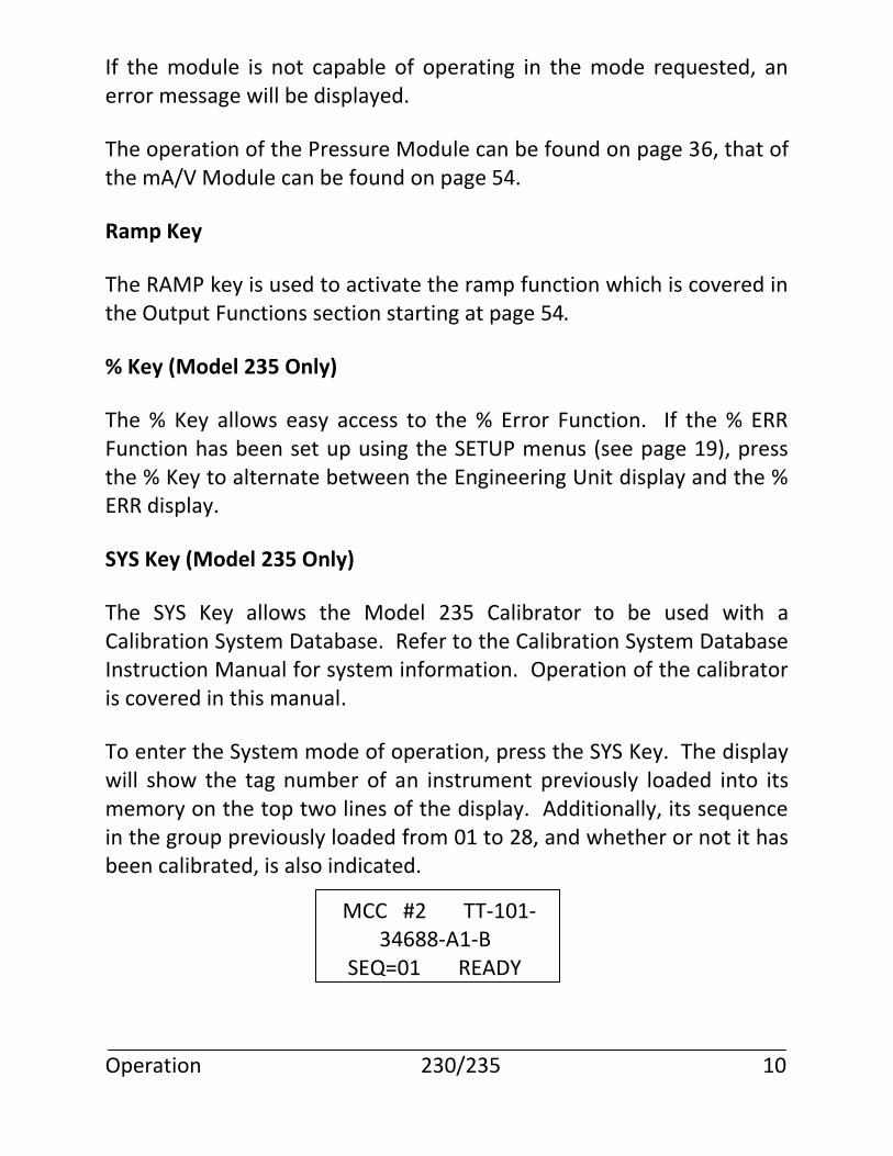
To enter the System mode of operation, press the SYS Key. The display will show the tag number of an instrument previously loaded into its memory on the top two lines of the display. Additionally, its sequence in the group previously loaded from 01 to 28, and whether or not it has been calibrated, is also indicated. Operation 230/235 10
MCC #2 TT-101- 34688-A1-B SEQ=01 READY
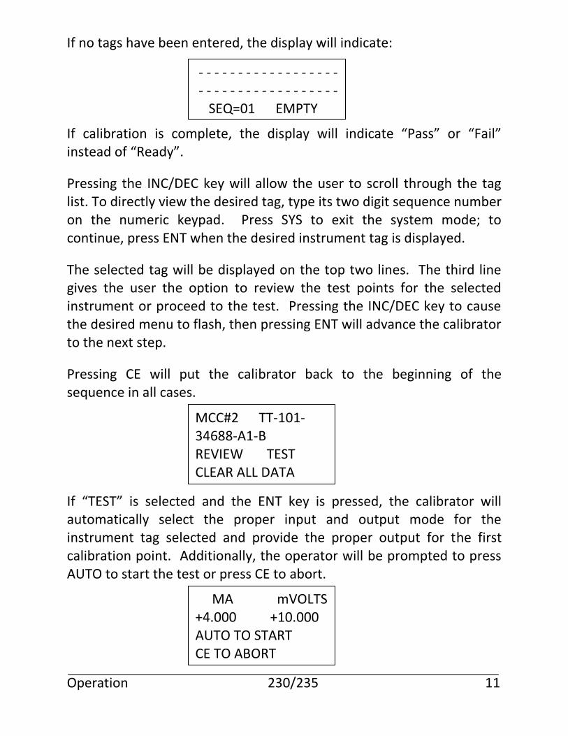
If no tags have been entered, the display will indicate: If calibration is complete, the display will indicate “Pass” or “Fail” instead of “Ready”.
Pressing the INC/DEC key will allow the user to scroll through the tag list. To directly view the desired tag, type its two digit sequence number on the numeric keypad. Press SYS to exit the system mode; to continue, press ENT when the desired instrument tag is displayed.
The selected tag will be displayed on the top two lines. The third line gives the user the option to review the test points for the selected instrument or proceed to the test. Pressing the INC/DEC key to cause the desired menu to flash, then pressing ENT will advance the calibrator to the next step.
Pressing CE will put the calibrator back to the beginning of the sequence in all cases. If “TEST” is selected and the ENT key is pressed, the calibrator will automatically select the proper input and output mode for the instrument tag selected and provide the proper output for the first calibration point. Additionally, the operator will be prompted to press AUTO to start the test or press CE to abort. Operation 230/235 11
- - - - - - - - - - - - - - - - - - - - - - - - - - - - - - - - - - - - SEQ=01 EMPTY
MCC#2 TT-101- 34688-A1-B REVIEW TEST CLEAR ALL DATA
MA mVOLTS +4.000 +10.000 AUTO TO START CE TO ABORT
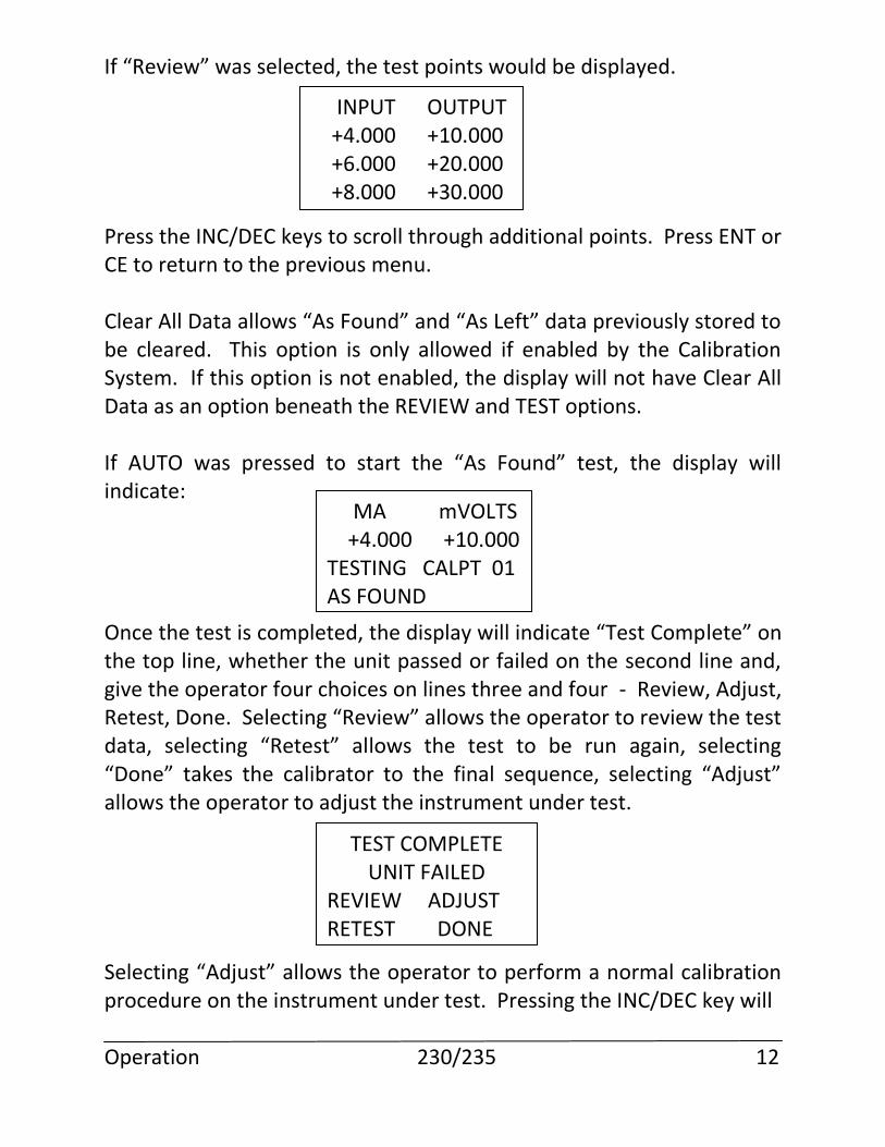
If “Review” was selected, the test points would be displayed. Press the INC/DEC keys to scroll through additional points. Press ENT or CE to return to the previous menu. Clear All Data allows “As Found” and “As Left” data previously stored to be cleared. This option is only allowed if enabled by the Calibration System. If this option is not enabled, the display will not have Clear All Data as an option beneath the REVIEW and TEST options. If AUTO was pressed to start the “As Found” test, the display will indicate: Once the test is completed, the display will indicate “Test Complete” on the top line, whether the unit passed or failed on the second line and, give the operator four choices on lines three and four - Review, Adjust, Retest, Done. Selecting “Review” allows the operator to review the test data, selecting “Retest” allows the test to be run again, selecting “Done” takes the calibrator to the final sequence, selecting “Adjust” allows the operator to adjust the instrument under test. Selecting “Adjust” allows the operator to perform a normal calibration procedure on the instrument under test. Pressing the INC/DEC key will Operation 230/235 12
INPUT OUTPUT +4.000 +10.000 +6.000 +20.000 +8.000 +30.000
MA mVOLTS +4.000 +10.000 TESTING CALPT 01 AS FOUND
TEST COMPLETE UNIT FAILED
REVIEW ADJUST RETEST DONE
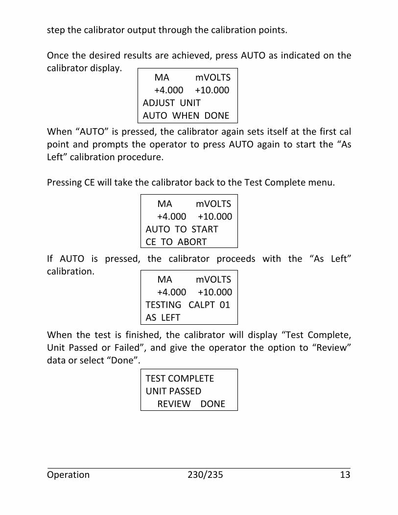
step the calibrator output through the calibration points. Once the desired results are achieved, press AUTO as indicated on the calibrator display. When “AUTO” is pressed, the calibrator again sets itself at the first cal point and prompts the operator to press AUTO again to start the “As Left” calibration procedure. Pressing CE will take the calibrator back to the Test Complete menu. If AUTO is pressed, the calibrator proceeds with the “As Left” calibration. When the test is finished, the calibrator will display “Test Complete, Unit Passed or Failed”, and give the operator the option to “Review” data or select “Done”. Operation 230/235 13
MA mVOLTS +4.000 +10.000 ADJUST UNIT AUTO WHEN DONE
MA mVOLTS +4.000 +10.000 AUTO TO START CE TO ABORT
MA mVOLTS +4.000 +10.000 TESTING CALPT 01 AS LEFT
TEST COMPLETE UNIT PASSED REVIEW DONE
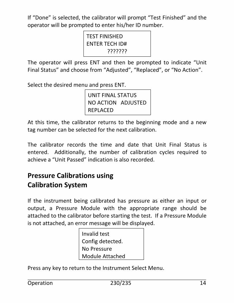
If “Done” is selected, the calibrator will prompt “Test Finished” and the operator will be prompted to enter his/her ID number. The operator will press ENT and then be prompted to indicate “Unit Final Status” and choose from “Adjusted”, “Replaced”, or “No Action”. Select the desired menu and press ENT. At this time, the calibrator returns to the beginning mode and a new tag number can be selected for the next calibration. The calibrator records the time and date that Unit Final Status is entered. Additionally, the number of calibration cycles required to achieve a “Unit Passed” indication is also recorded.
Pressure Calibrations using Calibration System
If the instrument being calibrated has pressure as either an input or output, a Pressure Module with the appropriate range should be attached to the calibrator before starting the test. If a Pressure Module is not attached, an error message will be displayed. Press any key to return to the Instrument Select Menu. Operation 230/235 14
TEST FINISHED ENTER TECH ID#
???????
UNIT FINAL STATUS NO ACTION ADJUSTED REPLACED
Invalid test Config detected. No Pressure Module Attached
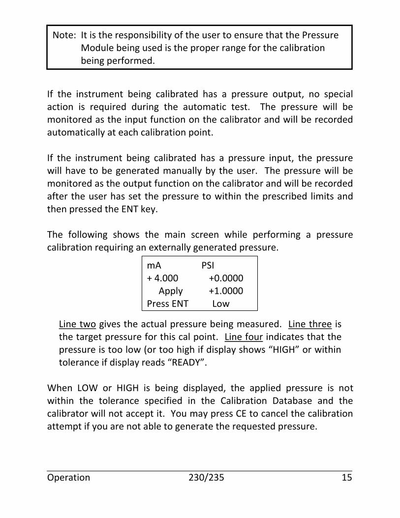
If the instrument being calibrated has a pressure output, no special action is required during the automatic test. The pressure will be monitored as the input function on the calibrator and will be recorded automatically at each calibration point. If the instrument being calibrated has a pressure input, the pressure will have to be generated manually by the user. The pressure will be monitored as the output function on the calibrator and will be recorded after the user has set the pressure to within the prescribed limits and then pressed the ENT key. The following shows the main screen while performing a pressure calibration requiring an externally generated pressure.
Line two gives the actual pressure being measured. Line three is the target pressure for this cal point. Line four indicates that the pressure is too low (or too high if display shows “HIGH” or within tolerance if display reads “READY”.
When LOW or HIGH is being displayed, the applied pressure is not within the tolerance specified in the Calibration Database and the calibrator will not accept it. You may press CE to cancel the calibration attempt if you are not able to generate the requested pressure. Operation 230/235 15
Note: It is the responsibility of the user to ensure that the Pressure Module being used is the proper range for the calibration being performed.
mA PSI + 4.000 +0.0000 Apply +1.0000 Press ENT Low
When READY is being displayed, the applied pressure is within tolerance. You should wait until the actual pressure readings stabilize and then press the ENT key. The calibrator will then store the readings and step to the next calibration point.
Manual Calibration using Calibration System
If the instrument being calibrated requires an input that cannot be generated by the calibrator or if the output of the instrument cannot be read by the calibrator, then the Calibration Database will indicate that the instrument has a Manual input or output.
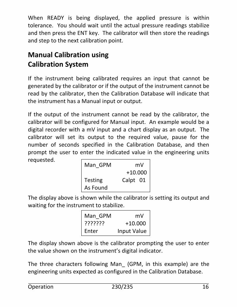
If the output of the instrument cannot be read by the calibrator, the calibrator will be configured for Manual input. An example would be a digital recorder with a mV input and a chart display as an output. The calibrator will set its output to the required value, pause for the number of seconds specified in the Calibration Database, and then prompt the user to enter the indicated value in the engineering units requested. The display above is shown while the calibrator is setting its output and waiting for the instrument to stabilize. The display shown above is the calibrator prompting the user to enter the value shown on the instrument’s digital indicator.
The three characters following Man_ (GPM, in this example) are the engineering units expected as configured in the Calibration Database. Operation 230/235 16
Man_GPM mV +10.000 Testing Calpt 01 As Found
Man_GPM mV ??????? +10.000 Enter Input Value
If the input to the instrument cannot be generated by the calibrator, the calibrator will be configured for Manual output. An example might be a magnetic flow meter that requires a manufacturer specific device to simulate a flow into its input.
There is an additional feature associated with Manual outputs. The Calibration Database can be configured to require that the user generate the exact value specified, or that the user generate approximately the values specified and then enter the exact value that was set.
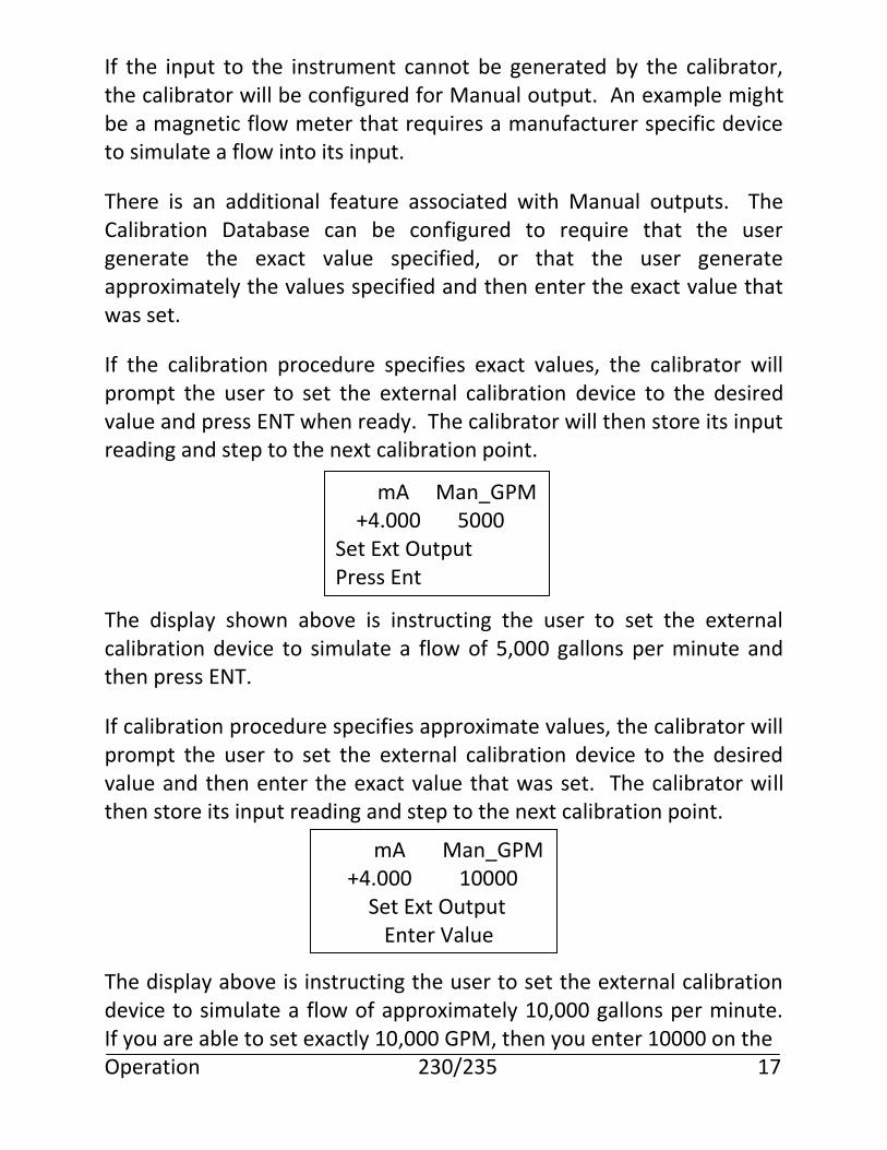
If the calibration procedure specifies exact values, the calibrator will prompt the user to set the external calibration device to the desired value and press ENT when ready. The calibrator will then store its input reading and step to the next calibration point. The display shown above is instructing the user to set the external calibration device to simulate a flow of 5,000 gallons per minute and then press ENT.
If calibration procedure specifies approximate values, the calibrator will prompt the user to set the external calibration device to the desired value and then enter the exact value that was set. The calibrator will then store its input reading and step to the next calibration point. The display above is instructing the user to set the external calibration device to simulate a flow of approximately 10,000 gallons per minute. If you are able to set exactly 10,000 GPM, then you enter 10000 on the Operation 230/235 17
mA Man_GPM +4.000 5000 Set Ext Output Press Ent
mA Man_GPM +4.000 10000 Set Ext Output Enter Value
numeric keypad and then press ENT. If the closest you could get to the desired value was 9,950 GPM, you would enter this value and press ENT. It is possible for an instrument to be configured for both Manual input and Manual output. An example might be a glass thermometer that is to be calibrated in a temperature bath. In this case the calibrator will first prompt for the user to set the external output and then prompt the user to enter the external input. Operation 230/235 18
Operator Setup
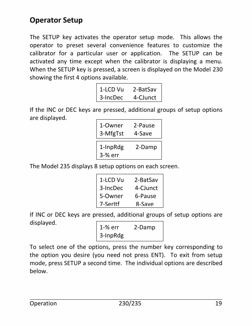
The SETUP key activates the operator setup mode. This allows the operator to preset several convenience features to customize the calibrator for a particular user or application. The SETUP can be activated any time except when the calibrator is displaying a menu. When the SETUP key is pressed, a screen is displayed on the Model 230 showing the first 4 options available. If the INC or DEC keys are pressed, additional groups of setup options are displayed. The Model 235 displays 8 setup options on each screen. If INC or DEC keys are pressed, additional groups of setup options are displayed. To select one of the options, press the number key corresponding to the option you desire (you need not press ENT). To exit from setup mode, press SETUP a second time. The individual options are described below. Operation 230/235 19
1-LCD Vu 2-BatSav 3-IncDec 4-CJunct
1-Owner 2-Pause 3-MfgTst 4-Save
1-InpRdg 2-Damp 3-% err
1-LCD Vu 2-BatSav 3-IncDec 4-CJunct 5-Owner 6-Pause 7-SerItf 8-Save
1-% err 2-Damp 3-InpRdg
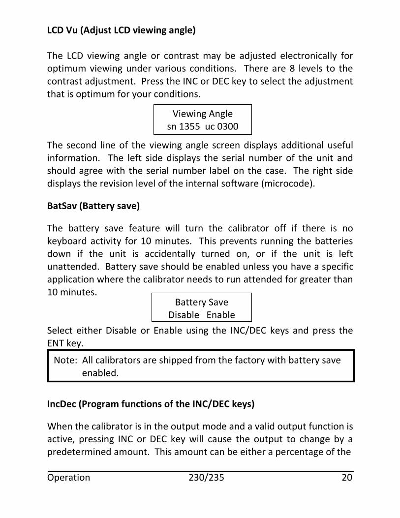
LCD Vu (Adjust LCD viewing angle) The LCD viewing angle or contrast may be adjusted electronically for optimum viewing under various conditions. There are 8 levels to the contrast adjustment. Press the INC or DEC key to select the adjustment that is optimum for your conditions. The second line of the viewing angle screen displays additional useful information. The left side displays the serial number of the unit and should agree with the serial number label on the case. The right side displays the revision level of the internal software (microcode).
BatSav (Battery save)
The battery save feature will turn the calibrator off if there is no keyboard activity for 10 minutes. This prevents running the batteries down if the unit is accidentally turned on, or if the unit is left unattended. Battery save should be enabled unless you have a specific application where the calibrator needs to run attended for greater than 10 minutes. Select either Disable or Enable using the INC/DEC keys and press the ENT key.
IncDec (Program functions of the INC/DEC keys)
When the calibrator is in the output mode and a valid output function is active, pressing INC or DEC key will cause the output to change by a predetermined amount. This amount can be either a percentage of the Operation 230/235 20
Viewing Angle sn 1355 uc 0300
Battery Save Disable Enable
Note: All calibrators are shipped from the factory with battery save enabled.
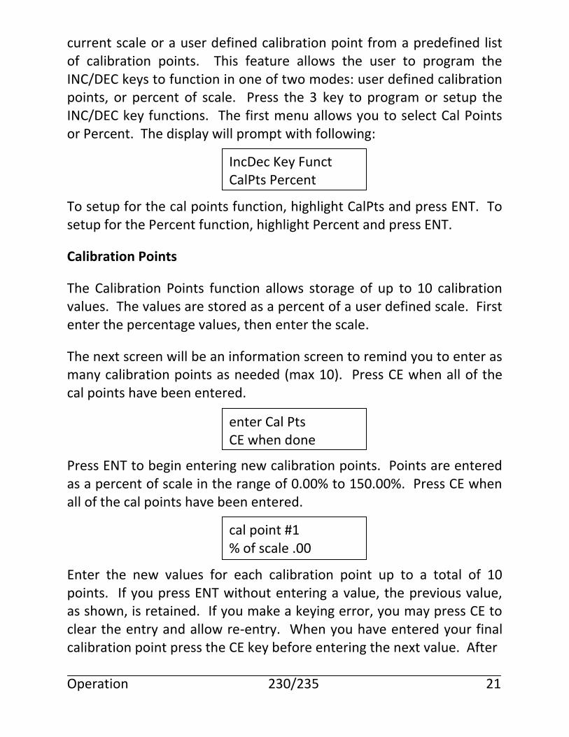
current scale or a user defined calibration point from a predefined list of calibration points. This feature allows the user to program the INC/DEC keys to function in one of two modes: user defined calibration points, or percent of scale. Press the 3 key to program or setup the INC/DEC key functions. The first menu allows you to select Cal Points or Percent. The display will prompt with following: To setup for the cal points function, highlight CalPts and press ENT. To setup for the Percent function, highlight Percent and press ENT.
Calibration Points
The Calibration Points function allows storage of up to 10 calibration values. The values are stored as a percent of a user defined scale. First enter the percentage values, then enter the scale.
The next screen will be an information screen to remind you to enter as many calibration points as needed (max 10). Press CE when all of the cal points have been entered. Press ENT to begin entering new calibration points. Points are entered as a percent of scale in the range of 0.00% to 150.00%. Press CE when all of the cal points have been entered. Enter the new values for each calibration point up to a total of 10 points. If you press ENT without entering a value, the previous value, as shown, is retained. If you make a keying error, you may press CE to clear the entry and allow re-entry. When you have entered your final calibration point press the CE key before entering the next value. After Operation 230/235 21
IncDec Key Funct CalPts Percent
enter Cal Pts CE when done
cal point #1 % of scale .00
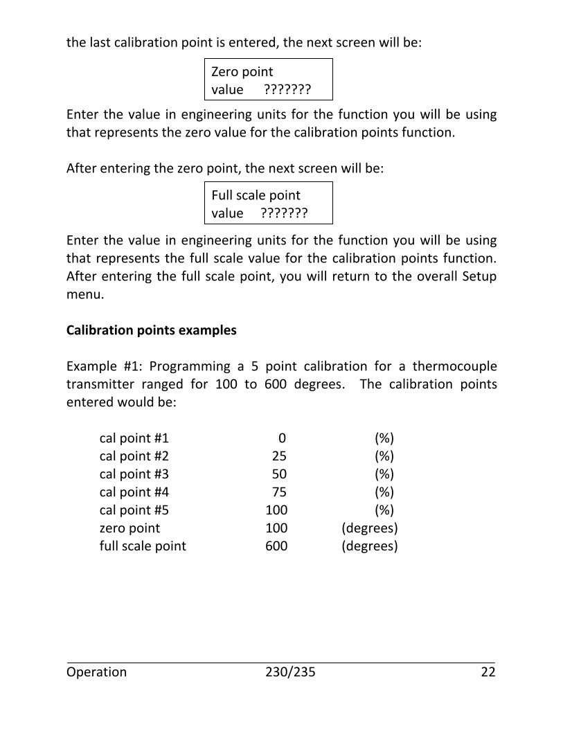
the last calibration point is entered, the next screen will be: Enter the value in engineering units for the function you will be using that represents the zero value for the calibration points function. After entering the zero point, the next screen will be: Enter the value in engineering units for the function you will be using that represents the full scale value for the calibration points function. After entering the full scale point, you will return to the overall Setup menu. Calibration points examples Example #1: Programming a 5 point calibration for a thermocouple transmitter ranged for 100 to 600 degrees. The calibration points entered would be: cal point #1 0 (%) cal point #2 25 (%) cal point #3 50 (%) cal point #4 75 (%) cal point #5 100 (%) zero point 100 (degrees) full scale point 600 (degrees) Operation 230/235 22
Zero point value ???????
Full scale point value ???????
Example #2: Programming a 3 point calibration for a 0-10mV input to a recorder. The calibration points entered would be: cal point #1 0 (%) cal point #2 50 (%) cal point #3 100 (%) zero point 0 (mvolts) full scale point 10 (mvolts) Utilizing Calibration Points Once calibration points have been enabled in the Setup Menu, they are activated by simply pressing the INC or DEC key after selecting the appropriate output function. The INC key steps forward through the calibration points list, and the DEC key steps backwards. If you attempt to step beyond the limits, the list will wrap around from the last to first when incrementing, or the first to last when decrementing. To automatically step through the selected calibration points, press the AUTO Key. The steps will continue until the AUTO Key is pressed again. Percent of Scale The percent of scale function allows the user to specify a fixed percentage that the output will change each time the INC or DEC key is pressed. Since the temperature scales have various ranges that would be difficult to remember, the temperature functions are setup to change by a fixed number of degrees. The range of values for percent are .01% to 100.00%; the range of values for temperature are .1 degree to 1000.0 degrees. The top line of the display lists the functions affected by the increase/decrease value. The second line shows whether the value is a percent of full scale or degrees. The current value is also shown. Operation 230/235 23
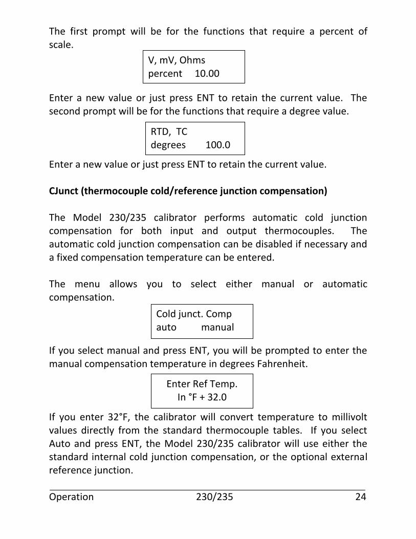
The first prompt will be for the functions that require a percent of scale. Enter a new value or just press ENT to retain the current value. The second prompt will be for the functions that require a degree value. Enter a new value or just press ENT to retain the current value. CJunct (thermocouple cold/reference junction compensation) The Model 230/235 calibrator performs automatic cold junction compensation for both input and output thermocouples. The automatic cold junction compensation can be disabled if necessary and a fixed compensation temperature can be entered. The menu allows you to select either manual or automatic compensation. If you select manual and press ENT, you will be prompted to enter the manual compensation temperature in degrees Fahrenheit. If you enter 32°F, the calibrator will convert temperature to millivolt values directly from the standard thermocouple tables. If you select Auto and press ENT, the Model 230/235 calibrator will use either the standard internal cold junction compensation, or the optional external reference junction. Operation 230/235 24
V, mV, Ohms percent 10.00
RTD, TC degrees 100.0
Cold junct. Comp auto manual
Enter Ref Temp. In °F + 32.0
The internal temperature compensation is performed by a semiconductor temperature sensor located next to the thermocouple output terminals. The external temperature compensation is performed in a special external module that connects to the Model 230/235 calibrator’s ECJ jack on the front panel. If automatic compensation is selected, the calibrator will display the current reference junction temperature reading. Press any key to continue. The calibrator will automatically use the external module if it is plugged into the ECJ jack; otherwise, the internal compensation will be used. The choice between internal or external is largely determined by environment. The internal sensor is slower to respond to changes in the ambient temperature. The external sensor, being outside of the calibrator case, can respond to ambient changes more quickly. Also, the external sensor can be extended to allow it to be placed in close proximity to the device being calibrated and to allow connection to short or inaccessible thermocouple leads. Owner (Enter owner’s name)
The Model 230/235 calibrator contains a security feature that allows the owner to enter a name or other identifying number into the calibrator’s non-volatile memory. The owner’s name cannot be changed unless the operator knows the unit’s access code. The access code is unique to each calibrator and is printed on the individual calibration sheet that is shipped with each calibrator. Operation 230/235 25
Note: This module must be used to obtain specified accuracy. Martel P/N 910200-001
Ref junc sensor rdg °F + 72.0
When the owner setup is selected, the operator is prompted to enter the access code. Enter the access code from the calibration sheet and press ENT. If the incorrect code is entered, an error message is displayed and the calibrator returns to the setup menu. If the correct code is entered, the next display will be the current owner on the top line with the leftmost character blinking. The name of the owner can be any alphanumeric combination of up to 16 characters. Different characters are selected by pressing the INC or DEC keys to scroll forward or backward through the alphabet. The space character is represented by the underscore in this mode. If held down, the INC and DEC keys will auto repeat to allow fast advancing through the alphabet. Once the correct character is displayed in the current position, press ENT to advance to the next character position.
You may back up to a previous position by pressing the CE key. After you have entered the last character and pressed ENT, you will be prompted to press ENT if everything is OK, or press CE to cancel the change. Press ENT if you are satisfied with the entry, or CE to cancel. If you press CE, the owner’s name will not be changed. If you press ENT, a momentary wait message will appear while the new information is written into the non-volatile memory. Operation 230/235 26
When a new calibrator is received, the owner should enter the desired owner name and file the access code in a safe place for future reference. DO NOT keep the access code with the calibrator.
_YOUR_NAME_HERE_
_NEW_OWNER_NAME_ ENT+OK CE+cancel
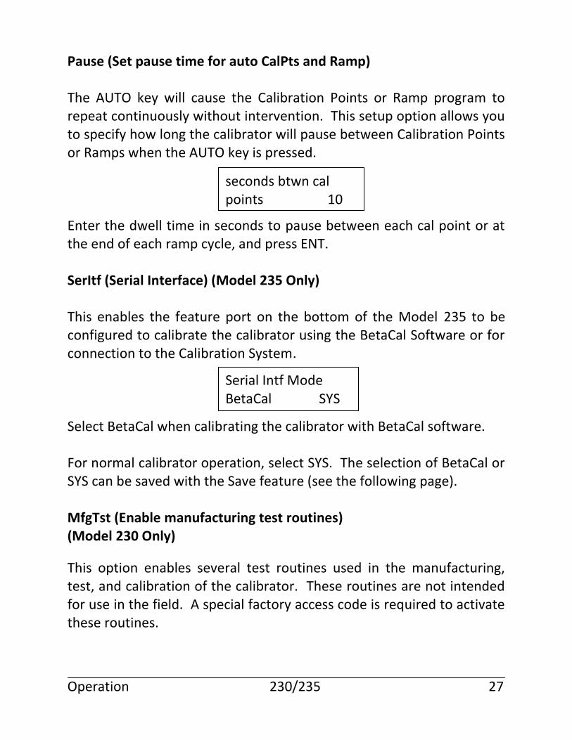
Pause (Set pause time for auto CalPts and Ramp) The AUTO key will cause the Calibration Points or Ramp program to repeat continuously without intervention. This setup option allows you to specify how long the calibrator will pause between Calibration Points or Ramps when the AUTO key is pressed. Enter the dwell time in seconds to pause between each cal point or at the end of each ramp cycle, and press ENT. SerItf (Serial Interface) (Model 235 Only) This enables the feature port on the bottom of the Model 235 to be configured to calibrate the calibrator using the BetaCal Software or for connection to the Calibration System. Select BetaCal when calibrating the calibrator with BetaCal software. For normal calibrator operation, select SYS. The selection of BetaCal or SYS can be saved with the Save feature (see the following page). MfgTst (Enable manufacturing test routines) (Model 230 Only)
This option enables several test routines used in the manufacturing, test, and calibration of the calibrator. These routines are not intended for use in the field. A special factory access code is required to activate these routines.
Operation 230/235 27
seconds btwn cal points 10
Serial Intf Mode BetaCal SYS
Save (Save setup values in non-volatile RAM)
This function allows the setup parameters that have been entered to be saved in non-volatile RAM. If the Setup mode is exited without saving (by pressing the SETUP key a second time), the setup parameters remain temporary in nature and will only be retained until the instrument is powered off.
The SAVE option will allow the setup parameters to be retained, even with power off, until they are changed by the operator.
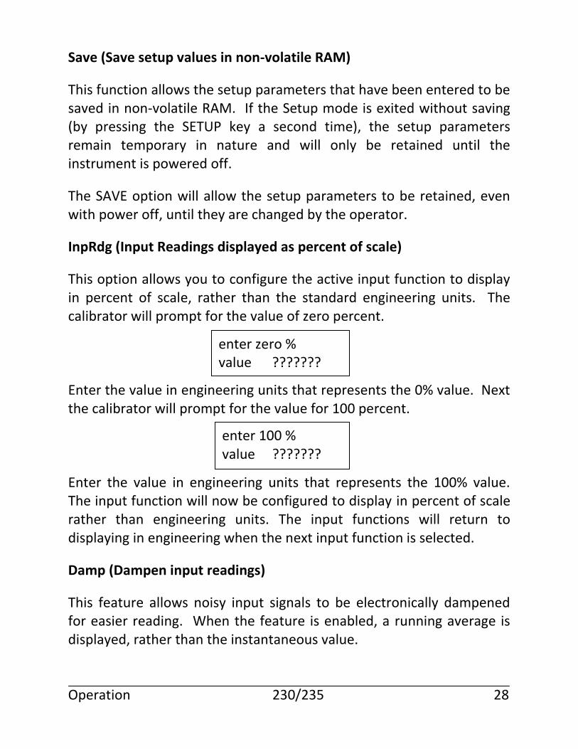
InpRdg (Input Readings displayed as percent of scale)
This option allows you to configure the active input function to display in percent of scale, rather than the standard engineering units. The calibrator will prompt for the value of zero percent. Enter the value in engineering units that represents the 0% value. Next the calibrator will prompt for the value for 100 percent. Enter the value in engineering units that represents the 100% value. The input function will now be configured to display in percent of scale rather than engineering units. The input functions will return to displaying in engineering when the next input function is selected.
Damp (Dampen input readings)
This feature allows noisy input signals to be electronically dampened for easier reading. When the feature is enabled, a running average is displayed, rather than the instantaneous value. Operation 230/235 28
enter zero % value ???????
enter 100 % value ???????
Select either Enable or Disable using the INC/DEC keys and press the ENT key.
% Error Display
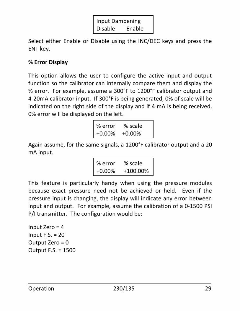
This option allows the user to configure the active input and output function so the calibrator can internally compare them and display the % error. For example, assume a 300°F to 1200°F calibrator output and 4-20mA calibrator input. If 300°F is being generated, 0% of scale will be indicated on the right side of the display and if 4 mA is being received, 0% error will be displayed on the left. Again assume, for the same signals, a 1200°F calibrator output and a 20 mA input. This feature is particularly handy when using the pressure modules because exact pressure need not be achieved or held. Even if the pressure input is changing, the display will indicate any error between input and output. For example, assume the calibration of a 0-1500 PSI P/I transmitter. The configuration would be:
Input Zero = 4 Input F.S. = 20 Output Zero = 0 Output F.S. = 1500
Operation 230/135 29
Input Dampening Disable Enable
% error % scale +0.00% +0.00%
% error % scale +0.00% +100.00%
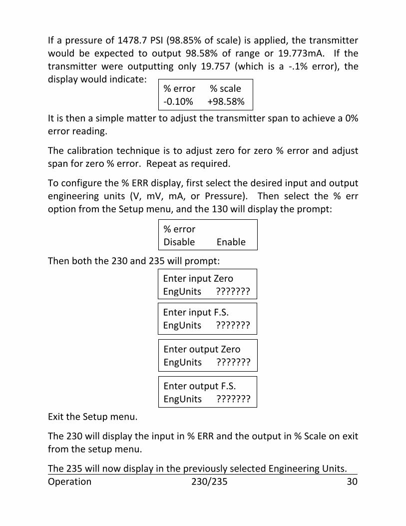
If a pressure of 1478.7 PSI (98.85% of scale) is applied, the transmitter would be expected to output 98.58% of range or 19.773mA. If the transmitter were outputting only 19.757 (which is a -.1% error), the display would indicate: It is then a simple matter to adjust the transmitter span to achieve a 0% error reading.
The calibration technique is to adjust zero for zero % error and adjust span for zero % error. Repeat as required.
To configure the % ERR display, first select the desired input and output engineering units (V, mV, mA, or Pressure). Then select the % err option from the Setup menu, and the 130 will display the prompt: Then both the 230 and 235 will prompt: Exit the Setup menu.
The 230 will display the input in % ERR and the output in % Scale on exit from the setup menu.
The 235 will now display in the previously selected Engineering Units. Operation 230/235 30
% error % scale -0.10% +98.58%
% error Disable Enable
Enter input Zero EngUnits ???????
Enter input F.S. EngUnits ???????
Enter output Zero EngUnits ???????
Enter output F.S. EngUnits ???????
To display the 235 input and output in % ERR and % Scale units, press the % Key. Subsequent presses of the % key, will toggle the 235 between engineering unit and % ERR/% Scale unit displays. Once the calibrator is turned off, all % Error setup are lost.
External Temperature Compensation Module
The External Temperature Compensation Module allows the calibrator to perform thermocouple calibration using copper wire and to operate under harsh temperature variations. Under normal circumstances, the calibrator should be connected to the instrument under test using the same type wire as the thermocouple being simulated. This allows differences in temperature between the calibrator and instrument to be compensated automatically. If the proper thermocouple wire is not available when making a calibration, the External Temperature Compensation Module may be extended from the calibrator using the Lead Extension Kit, and connected to the instrument with very short copper leads. The Module should then be positioned as close as possible to the instrument’s terminals, and allowed to stabilize to the instrument’s terminal temperature. When making thermocouple calibrations in extreme temperature conditions, the External Temperature Compensation Module must be used to provide optimum performance. The internal sensor response time may lag that of the module’s response time. The External Temperature Compensation Module can be attached to either the input or output TC jacks. The sensor plug attaches to the ECJ jack on the calibrator face. The calibrator will automatically switch to the External Module as soon as the sensor plug is attached. Operation 230/235 31
Input Functions
Input functions are selected by pressing any of the function keys while the calibrator is in input mode. Functions available on the Model 230/235 are Volts, Millivolts, Milliamps, Ohms, RTDs, and Thermocouples. Input mode is selected by pressing the INPUT key. The calibrator remains in input mode until the OUTPUT key is pressed. The cursor position on the display provides an indication of input or output mode. When the calibrator is in the input mode, the cursor is displayed in the leftmost column.
Input measurements are displayed on the left-hand side of the display. The engineering units are displayed on the top line, and the actual measurement value is displayed on the second line.
Volts/Millivolts
To measure Volts or Millivolts, press the V/mV (235) key when the calibrator is in the input mode. Pressing the V/mV key will cause the 235 to toggle between the two ranges. The 230 has separate V/mV keys. The Model 230/235 calibrator will begin making voltage measurements or millivolt measurements. Press the V/mV key to alternate between the two measurements. The calibrator will autorange between the 3 internal voltage ranges. The ranges available for millivolts are identical to the voltage ranges. The only difference between volts and millivolts is the format of the display.
Milliamps
To measure Milliamps, press the mA key when the calibrator is in the input mode. The calibrator will begin making current measurements and displaying Milliamps.
Input Functions 230/235 32
TC (Thermocouples)
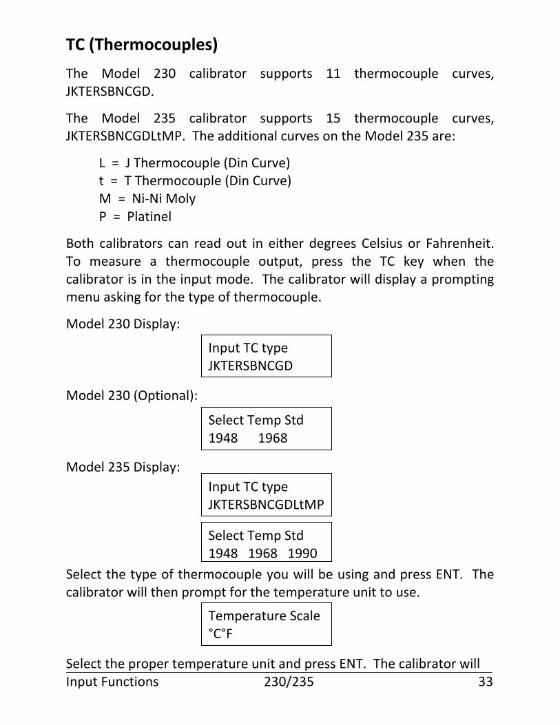
The Model 230 calibrator supports 11 thermocouple curves, JKTERSBNCGD.
The Model 235 calibrator supports 15 thermocouple curves, JKTERSBNCGDLtMP. The additional curves on the Model 235 are:
L = J Thermocouple (Din Curve) t = T Thermocouple (Din Curve) M = Ni-Ni Moly P = Platinel
Both calibrators can read out in either degrees Celsius or Fahrenheit. To measure a thermocouple output, press the TC key when the calibrator is in the input mode. The calibrator will display a prompting menu asking for the type of thermocouple.
Model 230 Display: Model 230 (Optional): Model 235 Display: Select the type of thermocouple you will be using and press ENT. The calibrator will then prompt for the temperature unit to use. Select the proper temperature unit and press ENT. The calibrator will Input Functions 230/235 33
Input TC type JKTERSBNCGD
Select Temp Std 1948 1968
Input TC type JKTERSBNCGDLtMP
Select Temp Std 1948 1968 1990
Temperature Scale °C°F
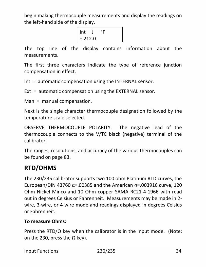
begin making thermocouple measurements and display the readings on the left-hand side of the display. The top line of the display contains information about the measurements.
The first three characters indicate the type of reference junction compensation in effect.
Int = automatic compensation using the INTERNAL sensor.
Ext = automatic compensation using the EXTERNAL sensor.
Man = manual compensation.
Next is the single character thermocouple designation followed by the temperature scale selected.
OBSERVE THERMOCOUPLE POLARITY. The negative lead of the thermocouple connects to the V/TC black (negative) terminal of the calibrator.
The ranges, resolutions, and accuracy of the various thermocouples can be found on page 83.
RTD/OHMS
The 230/235 calibrator supports two 100 ohm Platinum RTD curves, the European/DIN 43760 α=.00385 and the American α=.003916 curve, 120 Ohm Nickel Minco and 10 Ohm copper SAMA RC21-4-1966 with read out in degrees Celsius or Fahrenheit. Measurements may be made in 2-wire, 3-wire, or 4-wire mode and readings displayed in degrees Celsius or Fahrenheit.
To measure Ohms:
Press the RTD/Ω key when the calibrator is in the input mode. (Note: on the 230, press the Ω key). Input Functions 230/235 34
Int J °F + 212.0
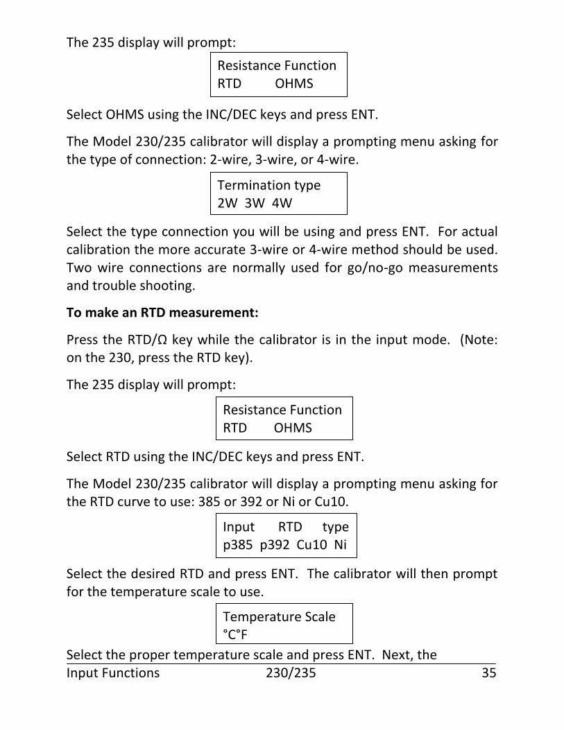
The 235 display will prompt: Select OHMS using the INC/DEC keys and press ENT.
The Model 230/235 calibrator will display a prompting menu asking for the type of connection: 2-wire, 3-wire, or 4-wire. Select the type connection you will be using and press ENT. For actual calibration the more accurate 3-wire or 4-wire method should be used. Two wire connections are normally used for go/no-go measurements and trouble shooting.
To make an RTD measurement:
Press the RTD/Ω key while the calibrator is in the input mode. (Note: on the 230, press the RTD key).
The 235 display will prompt: Select RTD using the INC/DEC keys and press ENT.
The Model 230/235 calibrator will display a prompting menu asking for the RTD curve to use: 385 or 392 or Ni or Cu10. Select the desired RTD and press ENT. The calibrator will then prompt for the temperature scale to use.
Select the proper temperature scale and press ENT. Next, the Input Functions 230/235 35
Resistance Function RTD OHMS
Termination type 2W 3W 4W
Resistance Function RTD OHMS
Input RTD type p385 p392 Cu10 Ni
Temperature Scale °C°F
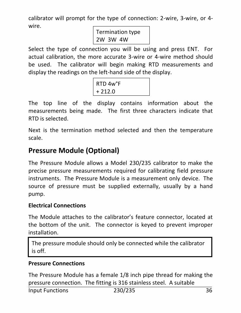
calibrator will prompt for the type of connection: 2-wire, 3-wire, or 4-wire. Select the type of connection you will be using and press ENT. For actual calibration, the more accurate 3-wire or 4-wire method should be used. The calibrator will begin making RTD measurements and display the readings on the left-hand side of the display. The top line of the display contains information about the measurements being made. The first three characters indicate that RTD is selected.
Next is the termination method selected and then the temperature scale.
Pressure Module (Optional)
The Pressure Module allows a Model 230/235 calibrator to make the precise pressure measurements required for calibrating field pressure instruments. The Pressure Module is a measurement only device. The source of pressure must be supplied externally, usually by a hand pump.
Electrical Connections
The Module attaches to the calibrator’s feature connector, located at the bottom of the unit. The connector is keyed to prevent improper installation. Pressure Connections
The Pressure Module has a female 1/8 inch pipe thread for making the pressure connection. The fitting is 316 stainless steel. A suitable Input Functions 230/235 36
The pressure module should only be connected while the calibrator is off.
Termination type 2W 3W 4W
RTD 4w°F + 212.0
thread lubricant should be used when making the connection to prevent seizing or galling.
Media Compatibility
The Pressure Module is designed to provide optimum accuracy as a secondary calibration device. It is not designed to be a general purpose test gauge to be attached to live processes. The low pressure ranges (0-100 PSIG) are compatible with non-corrosive gases. For long service with good stability and accuracy, clean, dry instrument air or nitrogen should be used. The high pressure ranges (300-5000 PSIG) are compatible with non-corrosive liquids and gases. The best liquid to use is distilled water.
Operation
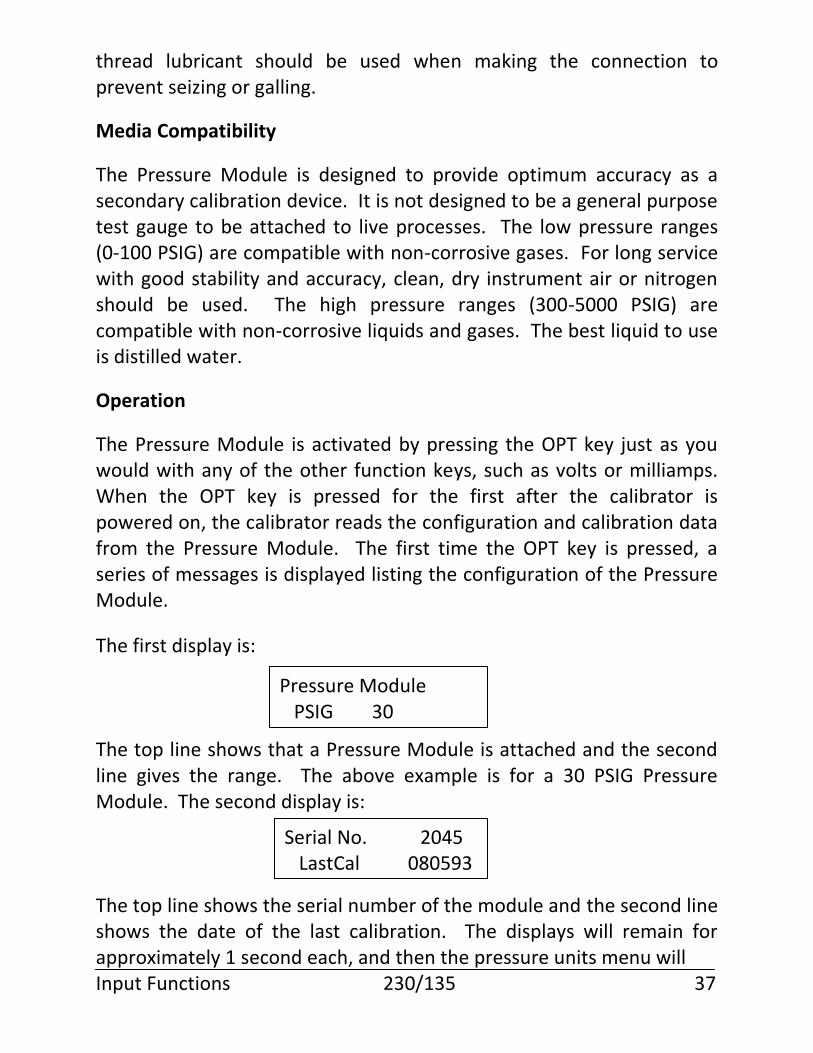
The Pressure Module is activated by pressing the OPT key just as you would with any of the other function keys, such as volts or milliamps. When the OPT key is pressed for the first after the calibrator is powered on, the calibrator reads the configuration and calibration data from the Pressure Module. The first time the OPT key is pressed, a series of messages is displayed listing the configuration of the Pressure Module.
The first display is: The top line shows that a Pressure Module is attached and the second line gives the range. The above example is for a 30 PSIG Pressure Module. The second display is: The top line shows the serial number of the module and the second line shows the date of the last calibration. The displays will remain for approximately 1 second each, and then the pressure units menu will Input Functions 230/135 37
Pressure Module PSIG 30
Serial No. 2045 LastCal 080593
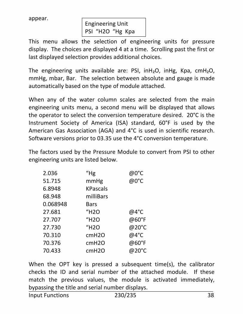
appear. This menu allows the selection of engineering units for pressure display. The choices are displayed 4 at a time. Scrolling past the first or last displayed selection provides additional choices.
The engineering units available are: PSI, inH₂O, inHg, Kpa, cmH₂O, mmHg, mbar, Bar. The selection between absolute and gauge is made automatically based on the type of module attached.
When any of the water column scales are selected from the main engineering units menu, a second menu will be displayed that allows the operator to select the conversion temperature desired. 20°C is the Instrument Society of America (ISA) standard, 60°F is used by the American Gas Association (AGA) and 4°C is used in scientific research. Software versions prior to 03.35 use the 4°C conversion temperature.
The factors used by the Pressure Module to convert from PSI to other engineering units are listed below.
2.036 “Hg @0°C 51.715 mmHg @0°C 6.8948 KPascals 68.948 milliBars 0.068948 Bars 27.681 “H2O @4°C 27.707 “H2O @60°F 27.730 “H2O @20°C 70.310 cmH2O @4°C 70.376 cmH2O @60°F 70.433 cmH2O @20°C
When the OPT key is pressed a subsequent time(s), the calibrator checks the ID and serial number of the attached module. If these match the previous values, the module is activated immediately, bypassing the title and serial number displays. Input Functions 230/235 38
Engineering Unit PSI “H2O “Hg Kpa
The Pressure Module is capable of operating as an input or output function, even though it is a measurement only device. This allows simultaneous measurement of pressure and milliamps if desired.
To operate the Pressure Module as an input function, press the OPT key while the calibrator is in the input mode. This will permit any allowable output function to be active simultaneously with pressure measurements.
To operate the Pressure Module as an output function, press the OPT key while the calibrator is in the output mode. This will allow pressure readings to be displayed on the output side, and milliamps to be displayed on the input side. In this mode, the calibrator is actually alternating readings between pressure and milliamps. This may cause a barely perceptible slowing of response time of the readings. If the simultaneously display of pressure and milliamps readings are not required, the Pressure Module should be operated as an input function for quickest response times. To reactivate pressure readings simply press the OPT Key after first selecting INPUT or OUTPUT mode as desired.
Zeroing a gauge pressure module
When a pressure module with a gauge pressure sensor is first activated, it will typically display a non-zero pressure reading. This is true even if the pressure is being displayed on the output side of the calibrator.
There may be a slight drift of the zero reading during the first few minutes of operation after power is first applied to the Pressure Module. The user should recheck the zero by venting any pressure and Input Functions 230/235 39
If pressure measurements are not being made, the calibrator should be turned off and the pressure module disconnected.
Note: To zero the reading, press the CE/Zero Key while the calibrator is in input mode.
observing the reading. If a shift has occurred, a new zero is obtained by pressing the CE/Zero Key while in input mode. Note that you must zero the pressure reading any time a new engineering unit is selected. Zeroing an absolute pressure module When a Pressure Module with an absolute sensor is used, the zero or offset procedure is modified to allow the user to enter the local barometric pressure as the zero. When the CE/Zero key is pressed, a prompting screen is displayed. Enter the local barometric pressure in the engineering units that are selected, and press ENT. The absolute pressure readings are then compensated by using the entered value as the reference pressure. There may be a slight drift of the zero reading during the first few minutes of operation after power is first applied to the Pressure Module. The user should recheck the zero by venting any pressure and observing the reading. If the reading does not match the local barometric pressure, a new zero is obtained by pressing the CE/Zero key while in input mode, and entering the barometric pressure. Note that you must enter the barometric zero any time a new engineering unit is selected. The barometric reference standard used should be .02% FS accuracy. Disconnected Pressure Module If the Pressure Module is disconnected while pressure readings are being made, the display will show invalid for the pressure reading. After a few seconds, the calibrator will determine that the Pressure Module has been disconnected or malfunctioned and the following display will be seen: Input Functions 230/235 40
Enter actual val ???????
Safety
Good safety practices should always be followed when using high pressures. Although liquids are considered non-compressible, dissolved gases and trapped gases can exist in the system and can store significant energy when compressed under high pressure. Always use good quality fittings that are rated for the pressures being used. Always wear safety glasses or goggles.
The ranges and resolution of the various pressure modules can be found on page 90.
Trip Detect
The trip detect feature is used in conjunction with the Ramp Function. Trip detect is a feature to aid in calibrating trip point alarms under simulated operating conditions. The ramp output of the calibrator simulates the changing process as an input to the alarm circuit.
The contact output of the alarm circuit connects back to the voltage input of the calibrator.
Input Functions 230/235 41
no external module present
The pressure adapter module receives power and commands from the calibrator’s output section and the pressure readings are made through the calibrator’s input section. As a result the calibrator loses its input to output isolation any time the pressure module is plugged into the feature connector. This is not a problem as far as pressure measurements are concerned. However, if you are operating the calibrator in a mode that requires input-output isolation, such as calibrating an E to E or I to E transmitter that is loop powered from an external 24V power supply, you MUST UNPLUG the pressure module. To be safe, you should disconnect the module anytime you are making simultaneous input-output electrical measurements.
The trip detect feature can utilize either the volts or 2-wire ohms input terminals. If the alarm circuit has powered contacts, the volts input should be used. If the alarm circuit has dry or non-powered contacts, the ohms 2-wire input should be used. If the voltage input is used, the maximum input voltage is 30 volts; however, the calibrator can only detect changes in the 0-10 volt range. This is normally not a problem, since the powered contacts typically switch between 0 volts and 24 volts.
A change of more than 1 volt or 100 ohms on the input is considered a change of state of the alarm circuit.
Trip detect is enabled when the Ramp Function is initiated. The final prompt when initiating the ramp is to enable or disable the trip detect function. If you enable the trip detect function, the final prompt will be to select ohms or volts and the input function will monitor for a significant change in its input measurement. When a change is detected, the output ramp is stopped and the current value is displayed.
The ramp is controlled by the INC/DEC keys. The first press of the INC or DEC key will cause the ramp output to assume the full scale or zero value, respectively. The second press of the key will cause the ramp to start and the input function to start monitoring for a change of state. When the change of state is detected, the ramp is stopped. Pressing the INC or DEC key again will restart the cycle. To test the dead band of an alarm, first initiate a positive going ramp using the INC key and record the trip point. Next initiate a negative going ramp using the DEC key and record the trip point again. The difference in the two recorded trip point values represents the dead band of the alarm.
While the ramp is running and before the trip occurs, the input display shows: Input Functions 230/235 42
After the trip occurs, the input display shows: To restart the ramp and reset the trip condition, press either the INC or DEC key once to reset the ramp to the starting or ending value and reset the tripped indication. Press the INC or DEC key a second time to start the ramp. Be sure to reset the external trip circuit if necessary before starting the ramp.
Min-Max Mode
The calibrator continuously stores the minimum and maximum values of the input readings. The min-max function allows these values to be displayed at any time.
To use the function, select the input variable to be displayed and press the INC key to display the minimum and maximum values recorded. The minimum and maximum values will be displayed until any key is pressed. Pressing any key will reset the min and max values to the most recent reading and the calibrator will return to displaying real time values. The minimum and maximum values are reset each time an input function is selected or re-selected.
Input Reading in Percent of Scale
This feature allows the input measurements to be displayed as a percent of scale rather than in engineering units. This allows error calculations in percent to be quickly calculated.
The feature is accessed through the Setup option InpRdg, and is normally utilized with output Calibration Points which are also programmed in percent of scale. Input Functions 230/235 43
Armed xxxxxx
Tripped xxxxxx
An example would be the testing of a thermocouple transmitter. The output CalPts would be setup for 0-25-50-75-100 percent and the zero and full scale points entered. Next the input mA function would be selected. Press SETUP and select the menu for InpRdg. Enter 4 as the zero point and 20 as the full scale point. Step through the CalPts using the INC key and observe the input readings. The transmitter’s error in percent of scale will be the observed reading minus the CalPts value. For example, if on the third calibration point (50%) the input reads 50.15, the error is 0.15% of scale (50.15-50.00). Input Functions 230/235 44
Output Functions
Output functions are selected by pressing any of the function keys while the calibrator is in output mode. Output functions available on the Model 230/235 are Volts, Millivolts, Ohms, RTDs, and Thermocouples. Output mode is selected by pressing the OUTPUT key. The calibrator remains in output mode until the INPUT key is pressed. The cursor position on the display provides an indication of input or output mode. When the calibrator is in output mode, the cursor is displayed in the rightmost column. Output measurements are displayed on the right-hand side of the display, with engineering units displayed on the top line and simulated value on the bottom. The output value displayed is the actual value at the output terminals, not simply the setpoint value.
Volts/Millivolts
To output Volts or Millivolts, press the V/mV key when the calibrator is in the Output mode. Pressing the V/mV key will cause the display to alternate between volts and millivolts. (Note: the 230 has separate V and mV keys. Press V for Volts and mV for Millivolts). The calibrator will prompt for the value desired. The calibrator will automatically select the proper range for the value entered. See page 85 for a description of the ranges and resolutions. Enter the desired voltage and press ENT. If an improper or out of range value is entered, the calibrator will display an error message. Error messages and their meanings are displayed on page 71. If the value is within the operating limits, the calibrator will set the output to the requested value. The output display will show the actual output Output Functions 230/235 45
VOLTS ??????
achieved at all times. The internal microprocessor will automatically correct for any drift due to temperature or battery change.
Millivolts
The millivolts output function is identical to the volt function except that the value is entered and displayed in millivolts.
TC (Thermocouples)
The Model 230 calibrator supports 11 thermocouple curves, JKTERSBNCGD.
The Model 235 calibrator supports 15 thermocouple curves, JKTERSBNCGDLtMP. The additional curves on the Model 235 are:
L = J Thermocouple (Din Curve) t = T Thermocouple (Din Curve) M = Ni-Ni Moly P = Platinel
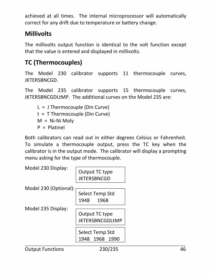
Both calibrators can read out in either degrees Celsius or Fahrenheit. To simulate a thermocouple output, press the TC key when the calibrator is in the output mode. The calibrator will display a prompting menu asking for the type of thermocouple.
Model 230 Display: Model 230 (Optional): Model 235 Display: Output Functions 230/235 46
Output TC type JKTERSBNCGD
Select Temp Std 1948 1968
Output TC type JKTERSBNCGDLtMP
Select Temp Std 1948 1968 1990
Select the type of thermocouple you will be using and press ENT. The calibrator will prompt for the temperature unit to use. Select the proper temperature unit and press ENT. The calibrator will prompt for the desired output temperature in degrees. Enter the desired temperature within the range of the selected thermocouple and press ENT. If an incorrect or out of range value is entered, the calibrator will display an error message and prompt again for a value. Once a valid temperature is entered the calibrator will set the output to the desired temperature. The display will reflect the actual temperature being simulated at the terminals as the calibrator adjusts its output to compensate for errors and drifts. When the display indicates the selected temperature, the output is properly set to simulate the requested thermocouple. The top line of the display contains information about the simulation being made.
The first three characters indicate the type of reference junction compensation in effect.
Int = automatic compensation using the INTERNAL sensor.
Ext = automatic compensation using the EXTERNAL sensor.
Man = manual compensation.
Next is the single character thermocouple designation followed by the temperature scale selected. Output Functions 230/235 47
Temperature Scale °C°F
Int J °F + 212.0
Temp ??????
OBSERVE THERMOCOUPLE POLARITY. THE RED V/TC TERMINAL OF THE CALIBRATOR IS THE POSITIVE TERMINAL. The calibrator should be connected to the device under test using the same type wire as the thermocouple being simulated. This will cause any difference in temperature between the calibrator’s reference terminals and the terminals of the unit under test to be compensated for automatically.
The ranges, resolutions, and accuracy of the various thermocouples can be found on page 86. Output functions 230/235 48
RTD/Ω Simulation
The calibrator output supports two 100 ohm Platinum RTD curves, the European/DIN 43760 α=.00385 and the American α=.003916 curve, 120 Ohm Nickel Minco and 10 Ohm copper SAMA RC21-4-1966 with read out in degrees Celsius or Fahrenheit. To simulate an RTD:
Press the RTD/Ω key while the calibrator is in the output mode. (Note: on the 230, press the RTD key).
The 235 display will prompt: Select the RTD function using the INC/DEC keys and press ENT.
The Model 230/235 calibrator will display a prompting menu asking for the RTD curve to use: 385 or 392 or Ni or Cu10. Select the desired RTD and press ENT. The calibrator will then prompt for the temperature scale to use.
Select the proper temperature scale and press ENT. The calibrator will prompt for the desired temperature. Enter the desired temperature within range of the RTD selected and press ENT. If an incorrect or out of range value is entered, the calibrator will display an error message and prompt for a value. Once a valid temperature is entered, the calibrator will set the output to the Output Functions 230/235 49
Resistance Function RTD OHMS
Input RTD type p385 p392 Cu10 Ni
Temperature Scale °C°F
Temp ??????
desired simulated temperature. The display readout will reflect the actual temperature being simulated at the terminals as the calibrator adjusts its output to compensate for errors and drift. When the display indicates the selected temperature, the output is properly set to simulate the requested RTD. The RTD simulation requires that the unit under test supply a nominal .1 to 2 milliamp test current. Pulsing excitation requires a minimum 60 mSecond pulse width, at 1 Hertz minimum, with no overshoot or ringing. If the calibrator detects that the current is absent or out of range, it will display OPEN or OVRANGE as appropriate. The polarity of the current is significant and is the same as the voltage terminals, i.e., red is positive. If the test current is of the incorrect polarity, the calibrator will display REVERSED. Simply reverse the leads at the calibrator or the devise under test. The top line of the display contains information about the measurements being made. The first three characters indicate that RTD is selected. Next is the temperature scale. Output Functions 230/235 50
RTD °F + 212.0
To simulate ohms: The Model 230/235 calibrator can simulate Ohms directly. This may be useful if the RTD does not conform to a standard curve or if the actual resistance in Ohms is needed. To select the Ohms output function, press the RTD/Ω key while the calibrator is in the output mode. (On the 230 press the Ω key). The 235 display will prompt: Select the Ohms function using the INC/DEC keys and press ENT. The Model 230/235 calibrator will prompt for the desired output in Ohms. Enter the desired value within the 0 to 1000 Ohm range and press ENT. If an incorrect or out of range value is entered, the calibrator will display an error message and prompt again for a value. Once a valid resistance is entered, the calibrator will set the output to the desired resistance. The display read-out will reflect the actual resistance being simulated at the terminals as the calibrator adjusts it output to compensate for error and drift. When the display indicates the selected resistance, the output is properly set to simulate the requested resistance. The Ohms simulation requires that the unit under test supply a nominal .1 to 2 milliamp test current. Pulsed excitation must meet specs as listed on page 87. If the calibrator detects that the current is absent or out of range, OPEN or OVRANGE, as appropriate, will be displayed. The Output Functions 230/235 51
Resistance Function RTD OHMS
OHMS ??????
polarity of the current is significant and is the same as the voltage terminals, i.e., red is positive. If the test current is of the incorrect polarity, the calibrator will display REVERSED. Simply reverse the leads at the calibrator or the devise under test.
Ramp Function
The ramp function provides an output ramp with adjustable rate and amplitude for volts, millivolts, and thermocouples. Before a ramp can be generated, select one of these output types. When the RAMP key is pressed, the following screen will be seen: Enter the starting value for the ramp in engineering units for the function you are using and press ENT. The next screen will be: Enter the ending value for the ramp in engineering units for the function you are using and press ENT. The ending value must be greater than the starting value.
The next screen will be: Enter the time in seconds for the ramp to slew from the starting value to the ending value. The range is 10 to 100,000 seconds. The next screen will be: If you want trip detect enabled for use with the ramp function, highlight Enable and press ENT. If you do not want trip detect enabled, highlight Disable and press ENT. See the description of Trip Detect for more information on this function. Output Functions 230/235 52
Starting value ??????
Ending value ??????
Ramp time secs ??????
Trip Detect Disable Enable
The next display will be: If enable is selected, the next display will prompt to select Volts or Ohms as the input. Once this selection is made, the calibrator will set the end point and the start point. The next display will be: Press the INC key to initiate the ramp from the starting value. Press the DEC key to initiate the ramp from the ending value. If the trip detect is enabled, you must press the INC or DEC key twice. See the trip detect description for more information. While the ramp is slewing, the display will show: The instantaneous value will be updating in the display. You will notice periodic pauses in the display as the calibrator does internal calibration cycles. This does not affect the output ramp and only causes a pause in the displayed value.
The ramp function is accomplished by updating the output digital to analog convertor (DAC) every 250 milliseconds with a new value. The amount of output change for each update is a function of the total ramp span and the length of time for the ramp to complete. The ramp is capable of 1 LSD resolution per update. The actual resolution, or amount of change per step, is dependent on the ramp amplitude and time. The following formula can be used to calculate the ramp resolution:
step size = (ending value – starting value) (ramp time x 4)
Output Functions 230/235 53
Sel Input Func Ohms Volts
Slewing xxxxxx
Volts RampRdy 0.00 xxxxxx
Calculate the ramp time to achieve a desired resolution using this formula.
ramp time = (ending value – starting value) (step size x 4)
Auto Mode
This function continuously repeats the calibration points or output ramp programs. If the ramp function is active when the AUTO key is pressed the ramp function is cycled continuously. If trip detect was enabled, it is canceled by the auto mode. If the ramp function is not active, then the CalPts are cycled repeatedly. If CalPts were not enabled, no action is taken.
mA/V Module (Optional)
The 20 Milliamp/10 Volt Output Module is an accessory for the Model 230/235 calibrator to allow it to generate either 0-20 mA or 0-10 volt outputs.
Installation
The module attaches to the calibrator’s feature connector at the base of the calibrator. The connector is keyed to prevent improper installation.
The module may be installed when the calibrator is turned on without causing any damage to the calibrator or module. The preferred installation method is to attach the module to the calibrator while the unit is turned off. This allows the module to initialize properly as the calibrator is turned on, the module should be initialized by pressing the OPT key before continuing to use normal calibration functions.
Operation
The module is activated by pressing the OPT key on the calibrator keypad while the calibrator is in the output mode. Output Functions 230/235 54
When the OPT Key is pressed for the first time after the calibrator is powered on, the calibrator reads the configuration and calibration data from the attached module. The first time the OPT Key is pressed, a series of messages is displayed listing the configuration of the module. The first display is: The top line shows that a 20 Milliamp/10 Volt Output module is attached to the calibrator. The second display is: The top line shows the serial number of the module and the second line shows the date of the last calibration. The displays will remain for approximately 1 second each, and then the final display will show: When the OPT key is pressed subsequently, the calibrator checks the ID and serial number of the attached module. If these match the previous values, the module is activated immediately, bypassing the 1st and 2nd displays listed above. To utilize the features of the module after it has been activated with the OPT key, the operator simply selects the milliamp or volts output function using the calibrator’s keypad. To generate a milliamp output, press the mA key while the calibrator is in the output mode. The calibrator will prompt for the value desired. Output Functions 230/235 55
20ma/10V output module
SerialNo 3046 LastCal 080593
20ma/10V output activated
mAMPS ??????
Enter the desired current in milliamps and press ENT. If an improper or out of range value is entered, the calibrator will display an error message. If the value is within the 0-22 mA operating limits, the calibrator will set the output to the requested value. The output displayed is the set point – not the actual output. To generate a voltage output, press the V key while the calibrator is in the output mode. (Note: the module should not be used for mV). The calibrator will ask whether to use the 0-10 Volt output from the module or the 0-1 volt output available at the calibrator’s output jacks. The display will show: Use the INC/DEC keys to select yes or no, and press ENT. If you select the “yes” option to use the 10V output module, the calibrator will accept values in the range of 0.0000 to 10.0000 and output the requested values at the module volts output jacks. If you select the “no” option to use the calibrator’s internal 0-1 volt output, the calibrator will accept values in the range of 0.000000 to 0.100000 and 0.100001 to 1.00000 volts and output the requested value at the calibrator’s volts output jacks. The module’s volts output jacks will be activated. Each time the volts option function is selected, the calibrator will give the operator the opportunity to use the calibrator or the module output provided that the module has been activated by pressing the OPT key. Each time that the milliamp or volts output function is selected, the calibrator will check that the module is still attached and operating properly. If the module does not respond properly, an error message will be displayed. Output Functions 230/235 56
Use 10V module? yes no
All of the output features such as Auto, CalPts and Ramp are available for use with the module.
Ohm/RTD Module (Optional)
The OHM/RTD Module allows output simulation of 1 to 900 Ohms by using the calibrator input to set the pots on the Module. Plug the umbilical from the Module into the Ohms input of the Model 230/235 calibrator and select 4-wire Ohms input. Move the switch on the Module to the Set position and set the desired output using the coarse and fine pots. Once the reading is achieved, move the switch to the Simulate position. Connect the instrument under test to the jacks on the OHM/RTD Module. Accuracy is the same as the Model 230/235 calibrators, resolution is better than .03 ohms.
Loop Power Supply (Optional)
The Loop Power Supply (LPS) is an option that provides 24 VDC to power a device under test. The LPS is shipped with the batteries in an uncharged state. The battery charger for the LPS is different from the one supplied with the Model 130/135 and 230/235 calibrators. Consult page 91 for proper part number. The LPS contains eight (8) AA Ni-Cd batteries that provide power to a DC to DC converter. This converter boosts the battery voltage (10.6 to 9.2 volts) to 24 VDC +/- 5%. The LPS is intended for use as a power supply for any two wire, 4 to 20 milliamp instrument requiring 24 VDC power. Battery life is 6 hours nominal at 20 milliamps. Full specifications can be found on page 91. Output Functions 230/235 57
Note: Before using the LPS as a portable unit, it is necessary to charge the batteries for a minimum of 14 to 16 hours.
The LPS is designed to turn itself ON and OFF automatically, based on current demand. When a series loop exists at the LPS Loop Power jacks calling for .5 milliamps or greater the LPS will automatically turn ON. Open the loop and power down occurs. This allows for maximum battery life by not allowing the unit to be left in the ON mode accidentally. The LPS can be used with or without the calibrator. When the test leads are connected from the LPS Loop Power connections to a device requiring power, the LPS automatically turns itself ON and provides 24VDC. Breaking the connections causes the LPS to automatically turn itself OFF, preventing needless battery drain. To use the calibrator with the LPS, simply plug the special connector provided with the LPS from the plug marked “To mA Input” on the LPS to the milliamp input terminals on the calibrator. This automatically puts the calibrator in series with the 4 to 20 milliamp loop. Plug the test leads provided with the calibrator into the jacks marked “Loop Power” on the LPS and connect them to the instrument under test, with proper polarity (+ to + / - to -). The batteries of the LPS can be checked by plugging the same special cable provided with the LPS from the plug marked “Battery Charger” on the LPS, to the V input jacks on the calibrator. When voltage is selected on the keypad, the LPS battery voltage will be displayed on the calibrator. The LPS battery voltage should be between 10.6 and 9.2 volts. When the voltage falls below 8.8 volts, the LPS will automatically turn itself OFF to prevent damage to the batteries due to possible cell reversal. Output Functions 230/235 58
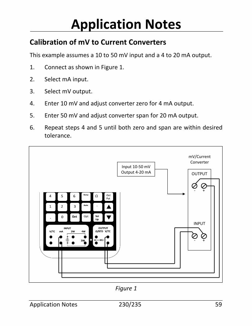
Application Notes
Calibration of mV to Current Converters
This example assumes a 10 to 50 mV input and a 4 to 20 mA output.
1. Connect as shown in Figure 1.
2. Select mA input.
3. Select mV output.
4. Enter 10 mV and adjust converter zero for 4 mA output.
5. Enter 50 mV and adjust converter span for 20 mA output.
6. Repeat steps 4 and 5 until both zero and span are within desired tolerance.
Figure 1
Application Notes 230/235 59
mV/Current Converter
OUTPUT
- +
INPUT
- +
Input 10-50 mV Output 4-20 mA
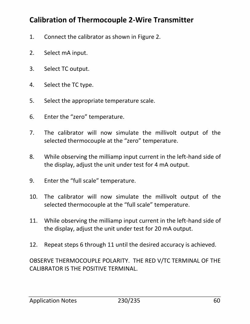
Calibration of Thermocouple 2-Wire Transmitter
1. Connect the calibrator as shown in Figure 2. 2. Select mA input. 3. Select TC output. 4. Select the TC type. 5. Select the appropriate temperature scale. 6. Enter the “zero” temperature. 7. The calibrator will now simulate the millivolt output of the
selected thermocouple at the “zero” temperature. 8. While observing the milliamp input current in the left-hand side of
the display, adjust the unit under test for 4 mA output. 9. Enter the “full scale” temperature. 10. The calibrator will now simulate the millivolt output of the
selected thermocouple at the “full scale” temperature. 11. While observing the milliamp input current in the left-hand side of
the display, adjust the unit under test for 20 mA output. 12. Repeat steps 6 through 11 until the desired accuracy is achieved. OBSERVE THERMOCOUPLE POLARITY. THE RED V/TC TERMINAL OF THE CALIBRATOR IS THE POSITIVE TERMINAL. Application Notes 230/235 60
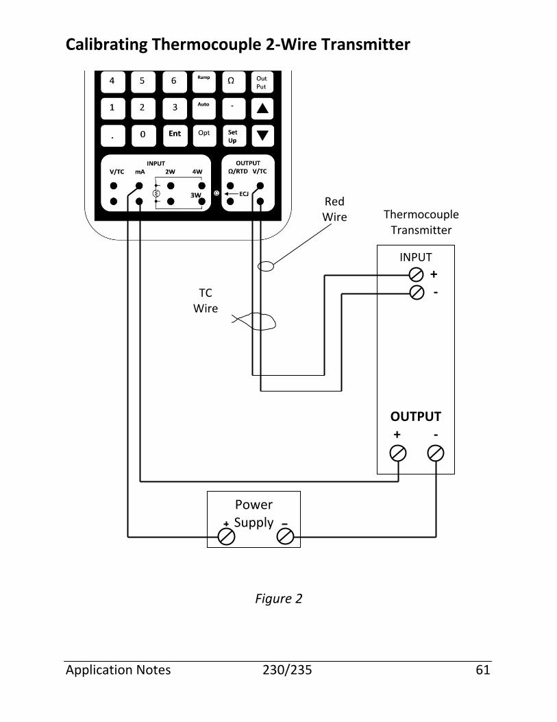
Calibrating Thermocouple 2-Wire Transmitter
Figure 2 Application Notes 230/235 61
INPUT
+ - OUTPUT + -
Power Supply
Red Wire Thermocouple
Transmitter
TC Wire
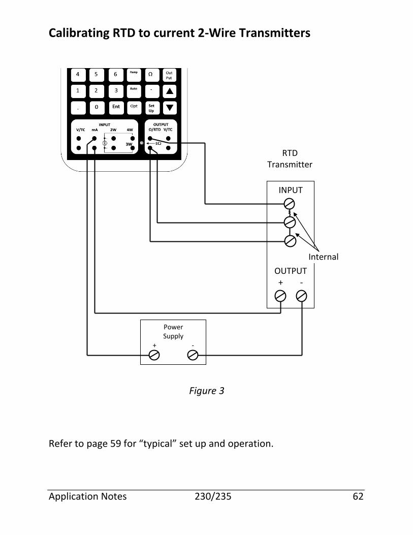
Calibrating RTD to current 2-Wire Transmitters
Figure 3 Refer to page 59 for “typical” set up and operation. Application Notes 230/235 62
INPUT
OUTPUT + -
Power Supply
+ -
Internal
RTD Transmitter
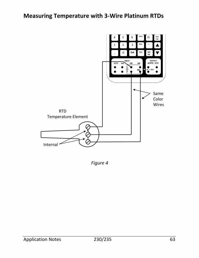
Measuring Temperature with 3-Wire Platinum RTDs
Figure 4 Application Notes 230/235 63
Internal
RTD Temperature Element
Same Color Wires
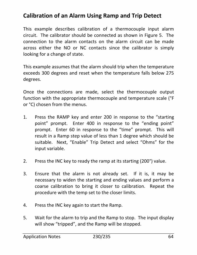
Calibration of an Alarm Using Ramp and Trip Detect
This example describes calibration of a thermocouple input alarm circuit. The calibrator should be connected as shown in Figure 5. The connection to the alarm contacts on the alarm circuit can be made across either the NO or NC contacts since the calibrator is simply looking for a change of state. This example assumes that the alarm should trip when the temperature exceeds 300 degrees and reset when the temperature falls below 275 degrees. Once the connections are made, select the thermocouple output function with the appropriate thermocouple and temperature scale (°F or °C) chosen from the menus. 1. Press the RAMP key and enter 200 in response to the “starting
point” prompt. Enter 400 in response to the “ending point” prompt. Enter 60 in response to the “time” prompt. This will result in a Ramp step value of less than 1 degree which should be suitable. Next, “Enable” Trip Detect and select “Ohms” for the input variable.
2. Press the INC key to ready the ramp at its starting (200°) value. 3. Ensure that the alarm is not already set. If it is, it may be
necessary to widen the starting and ending values and perform a coarse calibration to bring it closer to calibration. Repeat the procedure with the temp set to the closer limits.
4. Press the INC key again to start the Ramp. 5. Wait for the alarm to trip and the Ramp to stop. The input display
will show “tripped”, and the Ramp will be stopped. Application Notes 230/235 64
6. If the alarm trip point is not within the desired accuracy, adjust the alarm set point and repeat from step 2.
7. Press the DEC key to ready the ramp at its ending (400°) value. 8. Press the DEC key again to start the Ramp. 9. Wait for the alarm to reset. The input display will again display
“tripped” and the Ramp will be stopped. 10. If the alarm release point is not within the desired accuracy,
adjust it and repeat from step 7.
Figure 5
Application Notes 230/235 65
NO NC
INPUT - +
mA/V Module
The module provides a powered 4-20 mA output signal for calibrating the inputs to 4-20 mA controllers and indicators. This mode is used to calibrate instruments that are not providing the loop power. Figure 6 shows the module connected to an instrument that is not providing loop power. Equipment configuration may require that a loop be calibrated with the loop power supply energized. In this configuration, the calibrator’s internal power supply would oppose the loop power supply and the calibrator will not be able to generate the calibrating current. The module can be connected to a powered loop with the calibrator’s internal power supply aiding the external loop power supply as shown in Figure 7. This connection method is a simple polarity reversal of the standard powered milliamp configuration, sometimes called transmitter simulate mode. Application Notes 230/235 66
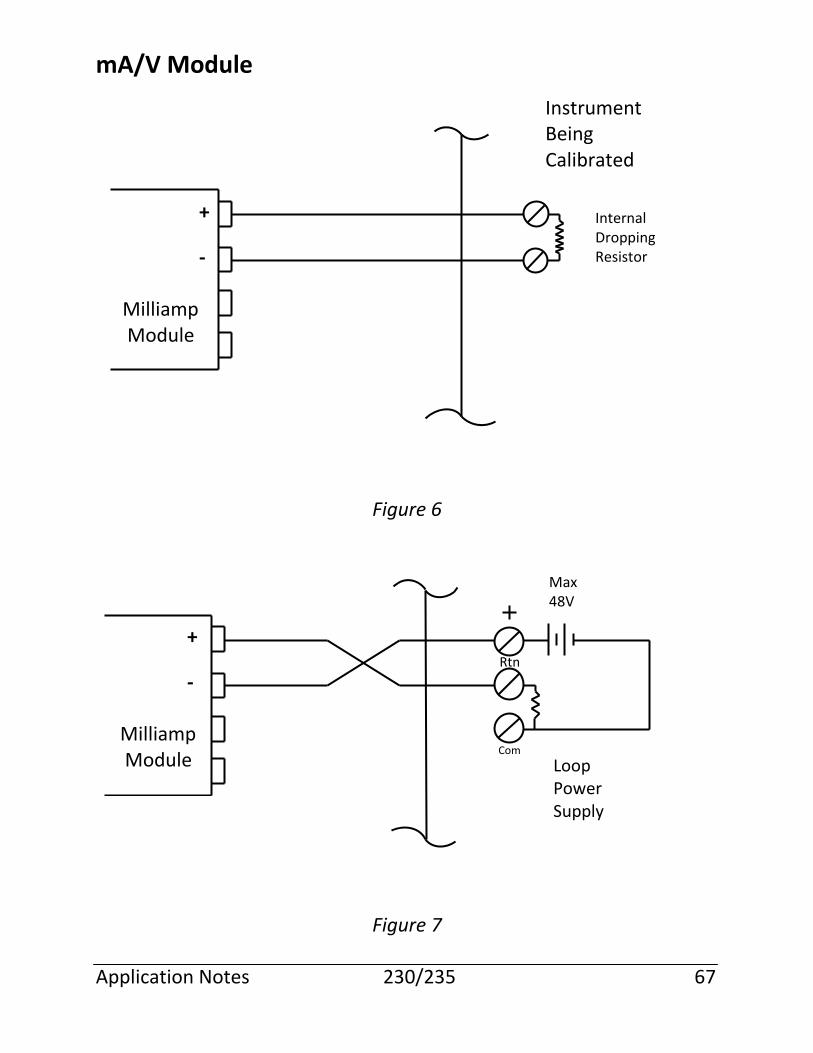
mA/V Module
Figure 6
Figure 7 Application Notes 230/235 67
+
- Milliamp Module
+
- Milliamp Module
Instrument Being Calibrated
Internal Dropping Resistor
Rtn
Com
Max 48V
Loop Power Supply
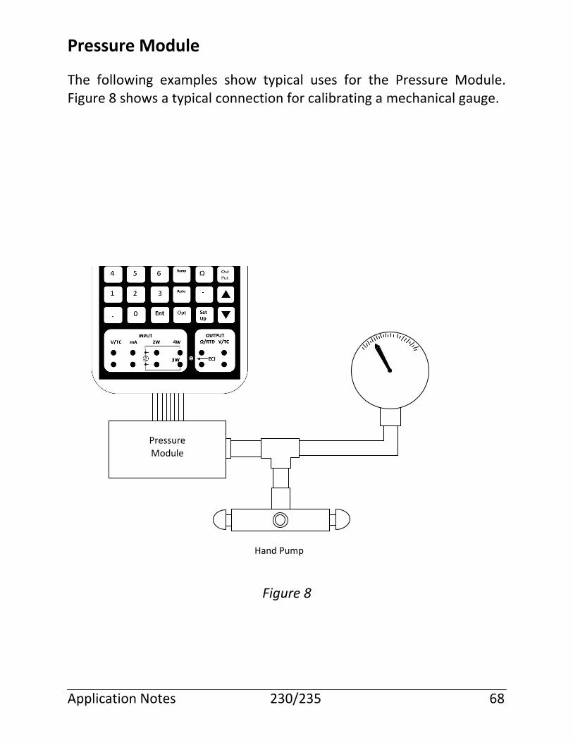
Pressure Module
The following examples show typical uses for the Pressure Module. Figure 8 shows a typical connection for calibrating a mechanical gauge.
Figure 8
Application Notes 230/235 68
Pressure Module
Hand Pump
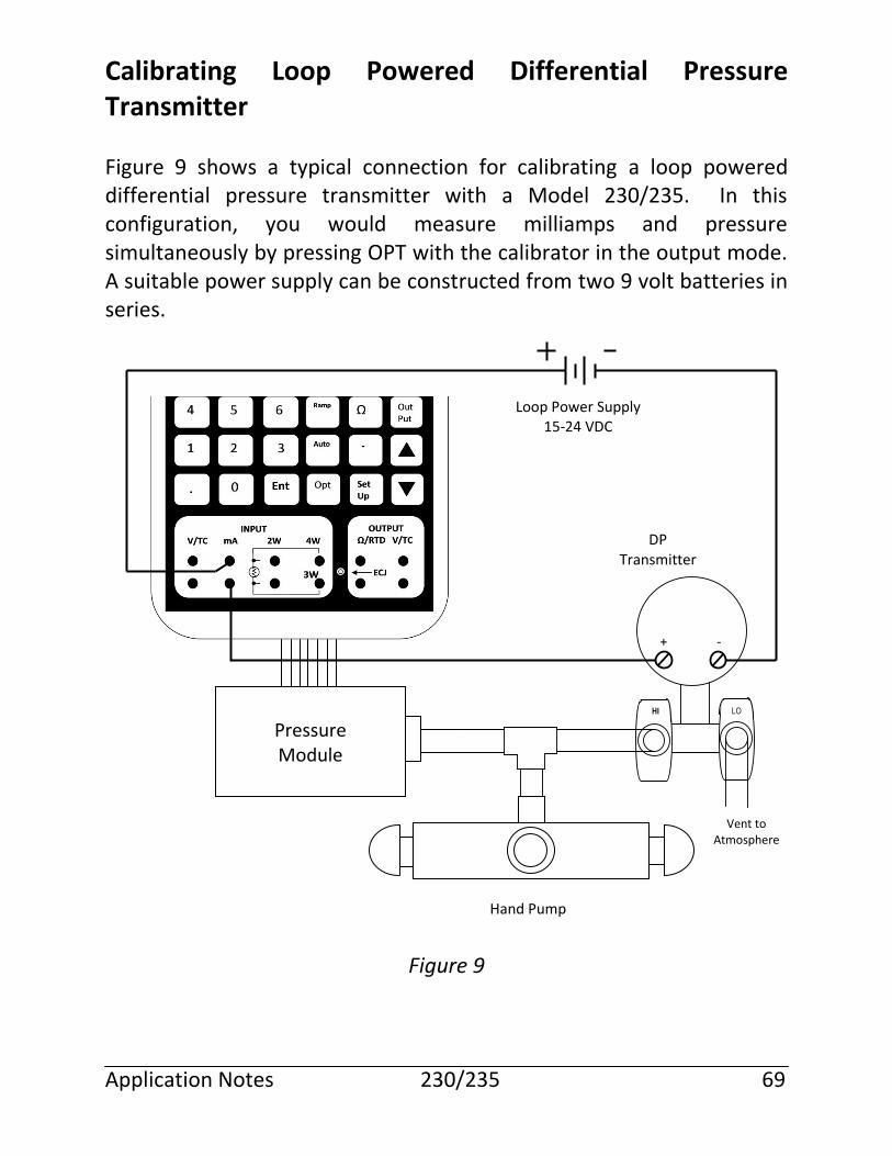
Calibrating Loop Powered Differential Pressure Transmitter
Figure 9 shows a typical connection for calibrating a loop powered differential pressure transmitter with a Model 230/235. In this configuration, you would measure milliamps and pressure simultaneously by pressing OPT with the calibrator in the output mode. A suitable power supply can be constructed from two 9 volt batteries in series.
Figure 9 Application Notes 230/235 69
Pressure Module
+ -
Vent to Atmosphere
Hand Pump
DP Transmitter
HI LO
Loop Power Supply 15-24 VDC
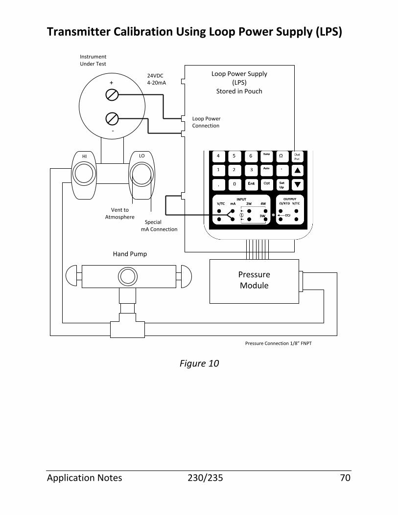
Transmitter Calibration Using Loop Power Supply (LPS)
Figure 10
Application Notes 230/235 70
Pressure Module
+
-
HI LO
Vent to Atmosphere
Special mA Connection
Hand Pump
Instrument Under Test
24VDC 4-20mA
Loop Power Connection
Loop Power Supply (LPS)
Stored in Pouch
Pressure Connection 1/8” FNPT
Error Messages
Entered value is out of range The value entered is outside of the allowable range for the current output function. Check the specifications for the function being used to determine the allowable range of values.
Expecting ENTER CE or INC/DEC The only keystrokes that are acceptable at this time are the ENTER, CE, INC or DEC.
Expecting ENTER or CE/CANCEL The only keystrokes that are acceptable at this time are the ENTER or CE (interpreted as Cancel).
Eeprom error Indicates that the calibrator failed the checksum of its eeprom. The user should have the calibrator serviced. The calibrator may still function in specification, but should be checked against reference standards prior to use. To use the calibrator when this error message occurs, press the ENTER key to bypass the eeprom error message.
Illegal key for current function The active function does not recognize the last key pressed. Review the instructions for the function you are using.
INPUT function not expecting data You are attempting to enter numeric data and the keyboard is in input mode. The keyboard should be in output mode (press the OUTPUT key) before entering numeric data.
Input section out of tolerance The input section of the calibrator is out of calibration tolerance to the extent that the calibrator is not usable. Power the calibrator off and back on to reset the error. If the error persists the calibrator must be serviced.
Error Messages 230/235 71
Input section fatal error det The input section of the calibrator has malfunctioned to the extent that the operation is not possible. Power the calibrator off and back on to reset the error. If the error persists the calibrator must be serviced.
KEY not implemented You have pressed a key that has no meaning.
No external module present You pressed the OPT key and there is no external module attached to the calibrator. If there is a module attached, turn the calibrator off and back on and attempt the operation again. If the error persists the module is probably defective.
No mode change in MENU/SETUP You have pressed the INPUT or OUTPUT key while a menu is active or in Setup mode. You must complete the menu or setup sequence before changing modes. You may cancel a menu by pressing CE or exit from Setup by pressing SETUP a second time.
No output mA available You have pressed the mA key while in output mode, and this calibrator does not have a Milliamp output function.
Output section out of tolerance The output section of the calibrator is out of calibration tolerance to the extent that the calibrator is not usable. Power the calibrator off and back on to reset the error. If the error persists the calibrator must be serviced.
Output section fatal error det The output section of the calibrator has malfunctioned to the extent that operation is not possible. Power the calibrator off and back on to reset the error. If the error persists the calibrator must be serviced.
Ramp not available for this function The selected output function does not support Ramp mode.
Error Messages 230/235 72
Unidentified err CalledBy ?????? An internal error has been detected by the calibrator firmware. Turn the calibrator off and back on to reset the error. If the problem persists, note the data in the lower right of the display and contact your service representative.
Wrong access code entered You entered the wrong access code when attempting to change the owner’s name or accessing the manufacturing test menu. The access code for changing the owner name is found on the factory calibration sheet. The access code for accessing the test menu is found in the BetaCal documentation for users who are performing their own calibrations.
mA/V Module Error Messages
entered value is out of range You may be attempting to output 1-10V without either activating the module with the OPTION key or responding YES to the “use 10V module?” prompt. No input funct. For this module The calibrator was in the input mode when the OPTION key was pressed. The calibrator should be in the output mode before attempting to activate this module. Sensor? The calibrator does not detect an internal or external temperature compensation sensor. Check ECJ connection. Error Messages 230/235 73
Service Information
Return for Calibration, Recertification or Repair
It is recommended that each calibrator be re-calibrated and/or recertified on an annual basis, and pressure modules re-calibrated and/or recertified on a 6 month basis, against precision standards that are traceable to the National Institute of Standards and Technology.
All returns should include a statement of the work requested and the exact address to which the unit should be returned. Martel Electronics will return units on a prepaid basis.
RETURN AUTHORIZATION
All equipment and/or parts to be returned to Martel Electronics for repair must have a Martel Electronics Return Material Authorization (RMA) form accompanying the equipment. The RMA form may be acquired by downloading it from the Martel Electronics website (www.Martelcorp.com) or by calling Martel Electronics (603) 434-1433 or toll free (800) 821-0023.
Please fill out all RMA forms as completely as possible. Customer name, address, and/or billing address when different from mailing address. Include description of equipment (i.e. model numbers, serial numbers, and quantities) along with purchase order number, description of work to be done, (if repair work a detailed explanation of the problem), and authorization to perform the work. This will ensure rapid service.
C.O.D. CHARGES WILL NOT BE ACCEPTED.
Ship Prepaid to: Martel Electronics Corporation 3 Corporate Park Drive, Unit 1 Derry, NH 03038 Attention: Service Department Service Information 230/235 74
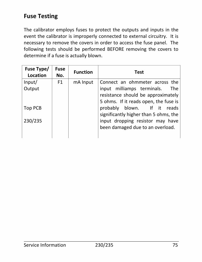
Fuse Testing
The calibrator employs fuses to protect the outputs and inputs in the event the calibrator is improperly connected to external circuitry. It is necessary to remove the covers in order to access the fuse panel. The following tests should be performed BEFORE removing the covers to determine if a fuse is actually blown.
Service Information 230/235 75
Fuse Type/ Location
Fuse No.
Function Test
Input/ Output Top PCB 230/235
F1 mA Input Connect an ohmmeter across the input milliamps terminals. The resistance should be approximately 5 ohms. If it reads open, the fuse is probably blown. If it reads significantly higher than 5 ohms, the input dropping resistor may have been damaged due to an overload.
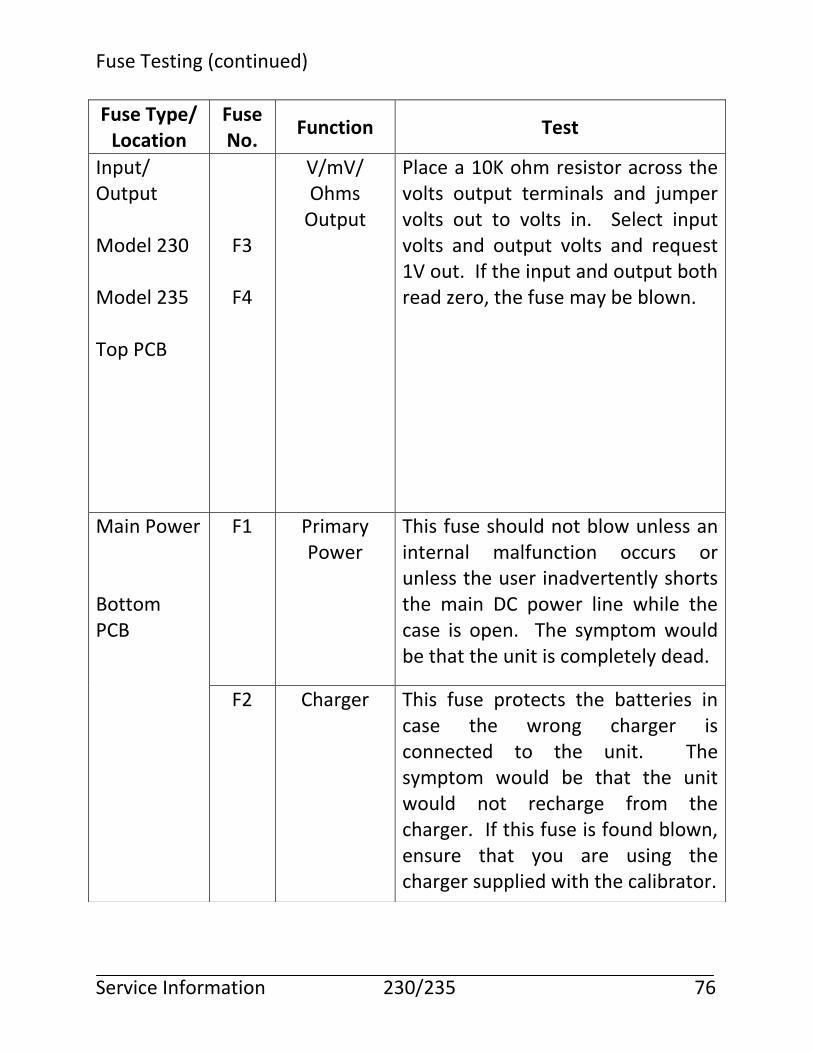
Fuse Testing (continued)
Service Information 230/235 76
Fuse Type/ Location
Fuse No.
Function Test
Input/ Output Model 230 Model 235 Top PCB
F3
F4
V/mV/ Ohms
Output
Place a 10K ohm resistor across the volts output terminals and jumper volts out to volts in. Select input volts and output volts and request 1V out. If the input and output both read zero, the fuse may be blown.
Main Power Bottom PCB
F1 Primary Power
This fuse should not blow unless an internal malfunction occurs or unless the user inadvertently shorts the main DC power line while the case is open. The symptom would be that the unit is completely dead.
F2 Charger This fuse protects the batteries in case the wrong charger is connected to the unit. The symptom would be that the unit would not recharge from the charger. If this fuse is found blown, ensure that you are using the charger supplied with the calibrator.
Fuse Replacement
Should it become necessary to change a fuse, take the following steps: 1. Turn the calibrator OFF. 2. Remove the 4 screws located at the corners on the bottom of the
unit. 3. Raise the cover at the top of the calibrator (end with the display)
until it clears the power supply and LCD display and then move the entire top towards the bottom about 1-2 inches. This will allow you to reach inside with your fingers and disconnect the keypad tail from the printed circuit card.
4. Determine the blown fuse from the table below and extract the
fuse using a small screwdriver or paper clip. All input/output fuses are located in the area of the input/output jacks, while the two main power fuses are located in the area of the battery charger jack. See page 80 for diagrams of the fuse areas.
Service Information 230/235 77
Read the following procedure fully and carefully before opening the case for fuse replacement. Damage to the keypad and/or keypad connector can occur if you do not follow these instructions.
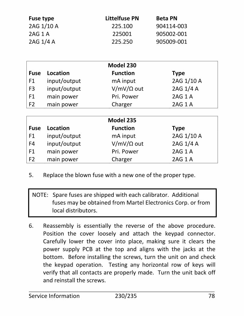
Fuse type Littelfuse PN Beta PN 2AG 1/10 A 225.100 904114-003 2AG 1 A 225001 905002-001 2AG 1/4 A 225.250 905009-001
Model 230 Fuse Location Function Type F1 input/output mA input 2AG 1/10 A F3 input/output V/mV/Ω out 2AG 1/4 A F1 main power Pri. Power 2AG 1 A F2 main power Charger 2AG 1 A
Model 235 Fuse Location Function Type F1 input/output mA input 2AG 1/10 A F4 input/output V/mV/Ω out 2AG 1/4 A F1 main power Pri. Power 2AG 1 A F2 main power Charger 2AG 1 A
5. Replace the blown fuse with a new one of the proper type.
6. Reassembly is essentially the reverse of the above procedure. Position the cover loosely and attach the keypad connector. Carefully lower the cover into place, making sure it clears the power supply PCB at the top and aligns with the jacks at the bottom. Before installing the screws, turn the unit on and check the keypad operation. Testing any horizontal row of keys will verify that all contacts are properly made. Turn the unit back off and reinstall the screws.
Service Information 230/235 78
NOTE: Spare fuses are shipped with each calibrator. Additional fuses may be obtained from Martel Electronics Corp. or from local distributors.
mA/V Module Service Information
The module contains a single 2AG 1/4A fuse in the milliamp output circuitry. To determine if the fuse is blown, measure the voltage from the milliamp positive (red) terminal to the volts negative (black) terminal. A reading of 12V indicates that the fuse is good. To replace the fuse, the module should be unplugged from the calibrator and opened by removing the two screws in the case and separating the halves. The module is powered from the calibrator, therefore there are no battery service requirements.
Service Information 230/235 79
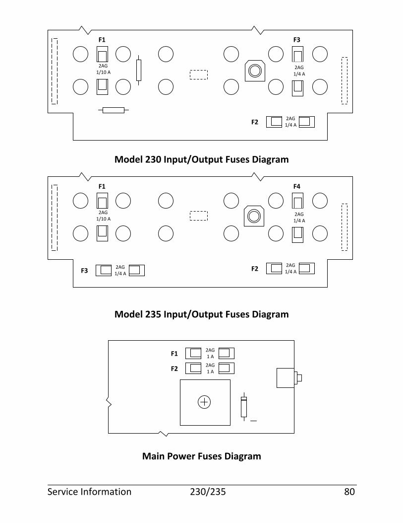
Model 230 Input/Output Fuses Diagram
Model 235 Input/Output Fuses Diagram
Main Power Fuses Diagram
Service Information 230/235 80
F1 F3
F2
2AG 1/10 A
2AG 1/4 A
2AG 1/4 A
F1 F4
F2
2AG 1/10 A
2AG 1/4 A
2AG 1/4 A F3
2AG 1/4 A
F2 2AG 1 A
F1 2AG 1 A
Warranty
Martel Electronics Corp. (Martel) devices are warranted to be free from all latent defects in material workmanship under normal use and service. Should any of Martel devices be found within one (1) year from date of shipment to be defective, Martel will repair such part and return to buyer FOB Martel’s plant or will furnish FOB Martel’s plant a similar part to replace it, provided written notice of such defect is given to Martel within ten (10) days after the discovery of such defect and provided the original part is returned to Martel’s plant with transportation charges prepaid. THE FOREGOING WARRANTIES ARE IN LIEU OF ALL WARRANTIES, EXPRESSED OR IMPLIED, INCLUDING BUT NOT LIMITED TO THE IMPLIED WARRANTIES OF MERCHANTABILITY AND FITNESS FOR A PARTICULAR PURPOSE. Service Information 230/235 81
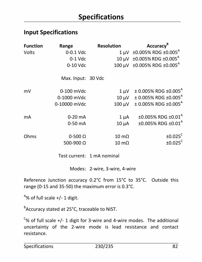
Specifications
Input Specifications
Function Range Resolution AccuracyB
Volts 0-0.1 Vdc 1 µV ±0.005% RDG ±0.005A 0-1 Vdc 10 µV ±0.005% RDG ±0.005A 0-10 Vdc 100 µV ±0.005% RDG ±0.005A
Max. Input: 30 Vdc mV 0-100 mVdc 1 µV ± 0.005% RDG ±0.005A 0-1000 mVdc 10 µV ± 0.005% RDG ±0.005A 0-10000 mVdc 100 µV ± 0.005% RDG ±0.005A mA 0-20 mA 1 µA ±0.005% RDG ±0.01A 0-50 mA 10 µA ±0.005% RDG ±0.01A Ohms 0-500 Ω 10 mΩ ±0.025C 500-900 Ω 10 mΩ ±0.025C
Test current: 1 mA nominal
Modes: 2-wire, 3-wire, 4-wire
Reference Junction accuracy 0.2°C from 15°C to 35°C. Outside this range (0-15 and 35-50) the maximum error is 0.3°C. A% of full scale +/- 1 digit. BAccuracy stated at 25°C, traceable to NIST. C% of full scale +/- 1 digit for 3-wire and 4-wire modes. The additional uncertainty of the 2-wire mode is lead resistance and contact resistance. Specifications 230/235 82

Thermocouples
TC RangeA ResolutionA AccuracyA
J -210 to -151 0.1 1 -150 to 1200 0.1 0.5 K -240 to -201 0.1 2 -200 to -101 0.1 1 -100 to 999 0.1 0.5 1000 to 1372 0.1 1 T -250 to -201 0.1 2 -200 to -101 0.1 1 -100 to 400 0.1 0.5 E -250 to -201 0.1 2 -200 to -101 0.1 1 -100 to 1000 0.1 0.5 R/S -50 to 299 1 1.7 300 to 1768 0.1 1.1 B 100 to 199 1 5 200 to 499 1 2 500 to 999 1 1.5 1000 to 1820 0.1 1 N -250 to -226 1 4 -225 to -101 1 2 -100 to 1300 0.1 1 G(4) 150 to 3210 1 5 C(5) 50 to 2310 1 5 D(6) 50 to 2310 1 5 L -200 to -151 0.1 1 -150 to 900 0.1 0.5 t -200 to -101 0.1 1 -100 to 600 0.1 0.5 M 0 to 1310 1 0.5 P 0 to 1400 1 0.5
AStated in degrees C. The external temperature compensation module PN910200-001 must be used to achieve stated accuracy. Specifications 230/235 83
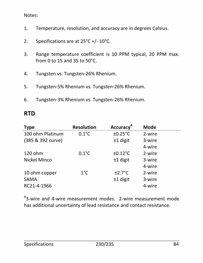
Notes: 1. Temperature, resolution, and accuracy are in degrees Celsius. 2. Specifications are at 25°C +/- 10°C. 3. Range temperature coefficient is 10 PPM typical, 20 PPM max.
from 0 to 15 and 35 to 50°C. 4. Tungsten vs. Tungsten-26% Rhenium. 5. Tungsten-5% Rhenium vs. Tungsten-26% Rhenium. 6. Tungsten-3% Rhenium vs. Tungsten-26% Rhenium.
RTD
Type Resolution AccuracyA Mode
100 ohm Platinum 0.1°C ±0.25°C 2-wire (385 & 392 curve) ±1 digit 3-wire 4-wire 120 ohm 0.1°C ±0.12°C 2-wire Nickel Minco ±1 digit 3-wire 4-wire 10 ohm copper 1°C ±2.7°C 2-wire SAMA ±1 digit 3-wire RC21-4-1966 4-wire A3-wire and 4-wire measurement modes. 2-wire measurement mode has additional uncertainty of lead resistance and contact resistance. Specifications 230/235 84
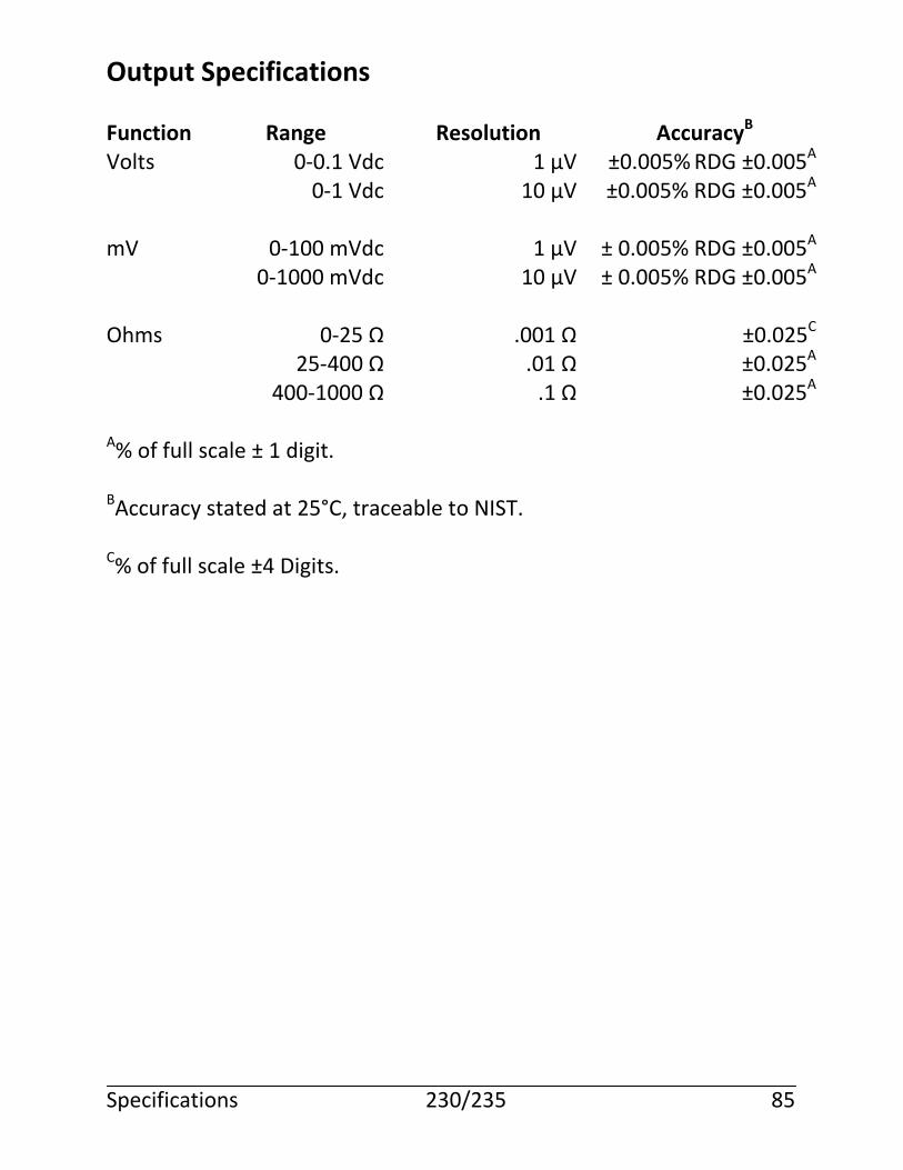
Output Specifications
Function Range Resolution AccuracyB
Volts 0-0.1 Vdc 1 µV ±0.005% RDG ±0.005A 0-1 Vdc 10 µV ±0.005% RDG ±0.005A mV 0-100 mVdc 1 µV ± 0.005% RDG ±0.005A 0-1000 mVdc 10 µV ± 0.005% RDG ±0.005A Ohms 0-25 Ω .001 Ω ±0.025C
25-400 Ω .01 Ω ±0.025A 400-1000 Ω .1 Ω ±0.025A
A% of full scale ± 1 digit. BAccuracy stated at 25°C, traceable to NIST. C% of full scale ±4 Digits.
Specifications 230/235 85

Thermocouples
TC RangeA ResolutionA AccuracyA
J -210 to -151 0.1 1 -150 to 1200 0.1 0.5 K -240 to -201 0.1 2 -200 to -101 0.1 1 -100 to 999 0.1 0.5 1000 to 1372 0.1 1 T -250 to -201 0.1 2 -200 to -101 0.1 1 -100 to 400 0.1 0.5 E -250 to -201 0.1 2 -200 to -101 0.1 1 -100 to 1000 0.1 0.5 R/S -50 to 299 1 1.7 300 to 1768 0.1 1.1 B 100 to 199 1 5 200 to 499 1 2 500 to 999 1 1.5 1000 to 1820 0.1 1 N -250 to -226 1 4 -225 to -101 1 2 -100 to 1300 0.1 1 G(4) 150 to 3210 1 5 C(5) 50 to 2310 1 5 D(6) 50 to 2310 1 5 L -200 to -151 0.1 1 -150 to 900 0.1 0.5 t -200 to -101 0.1 1 -100 to 600 0.1 0.5 M 0 to 1310 1 0.5 P 0 to 1400 1 0.5
AStated in degrees C. The external temperature compensation module PN910200-001 must be used to achieve stated accuracy. Specifications 230/235 86
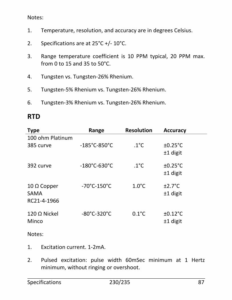
Notes:
1. Temperature, resolution, and accuracy are in degrees Celsius.
2. Specifications are at 25°C +/- 10°C.
3. Range temperature coefficient is 10 PPM typical, 20 PPM max. from 0 to 15 and 35 to 50°C.
4. Tungsten vs. Tungsten-26% Rhenium.
5. Tungsten-5% Rhenium vs. Tungsten-26% Rhenium.
6. Tungsten-3% Rhenium vs. Tungsten-26% Rhenium.
RTD
Type Range Resolution Accuracy
100 ohm Platinum 385 curve -185°C-850°C .1°C ±0.25°C ±1 digit
392 curve -180°C-630°C .1°C ±0.25°C ±1 digit
10 Ω Copper -70°C-150°C 1.0°C ±2.7°C SAMA ±1 digit RC21-4-1966
120 Ω Nickel -80°C-320°C 0.1°C ±0.12°C Minco ±1 digit
Notes:
1. Excitation current. 1-2mA.
2. Pulsed excitation: pulse width 60mSec minimum at 1 Hertz minimum, without ringing or overshoot.
Specifications 230/235 87
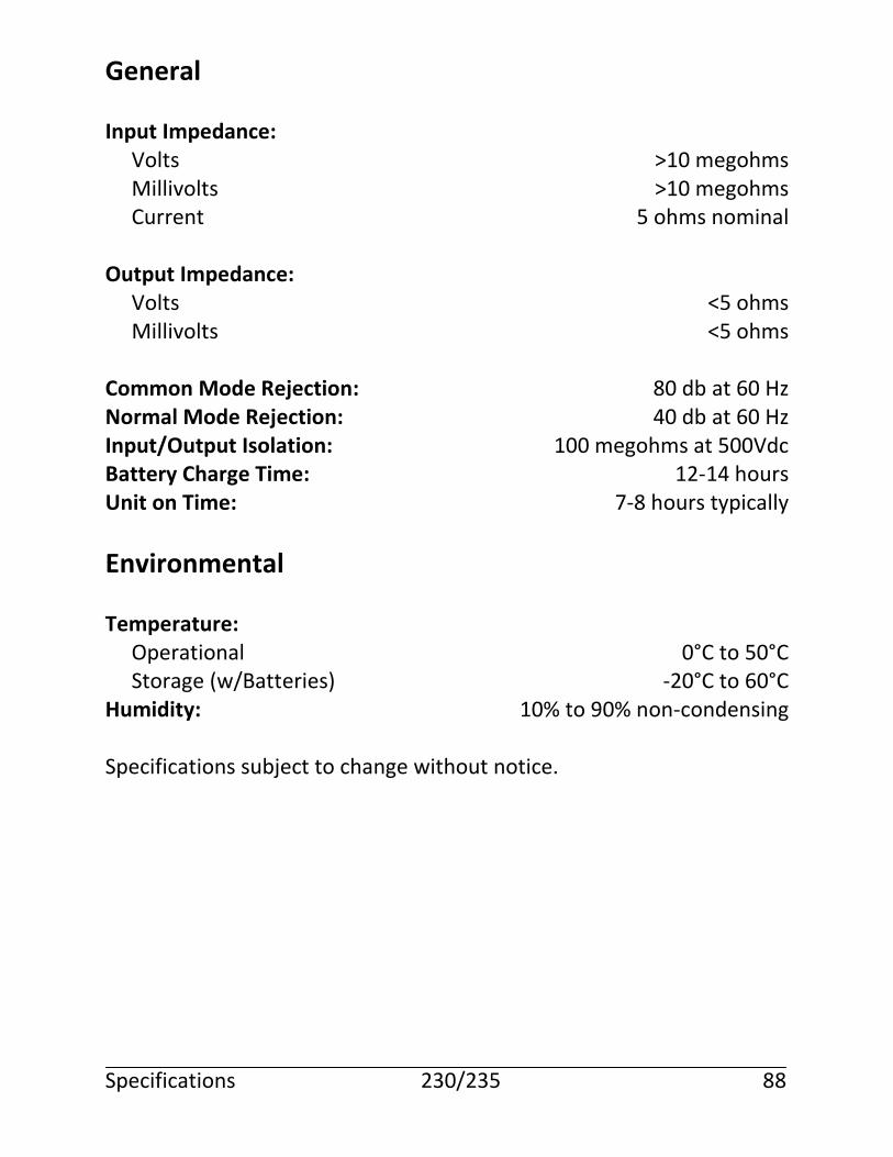
General Input Impedance: Volts >10 megohms Millivolts >10 megohms Current 5 ohms nominal Output Impedance: Volts <5 ohms Millivolts <5 ohms Common Mode Rejection: 80 db at 60 Hz Normal Mode Rejection: 40 db at 60 Hz Input/Output Isolation: 100 megohms at 500Vdc Battery Charge Time: 12-14 hours Unit on Time: 7-8 hours typically
Environmental Temperature: Operational 0°C to 50°C Storage (w/Batteries) -20°C to 60°C Humidity: 10% to 90% non-condensing Specifications subject to change without notice. Specifications 230/235 88
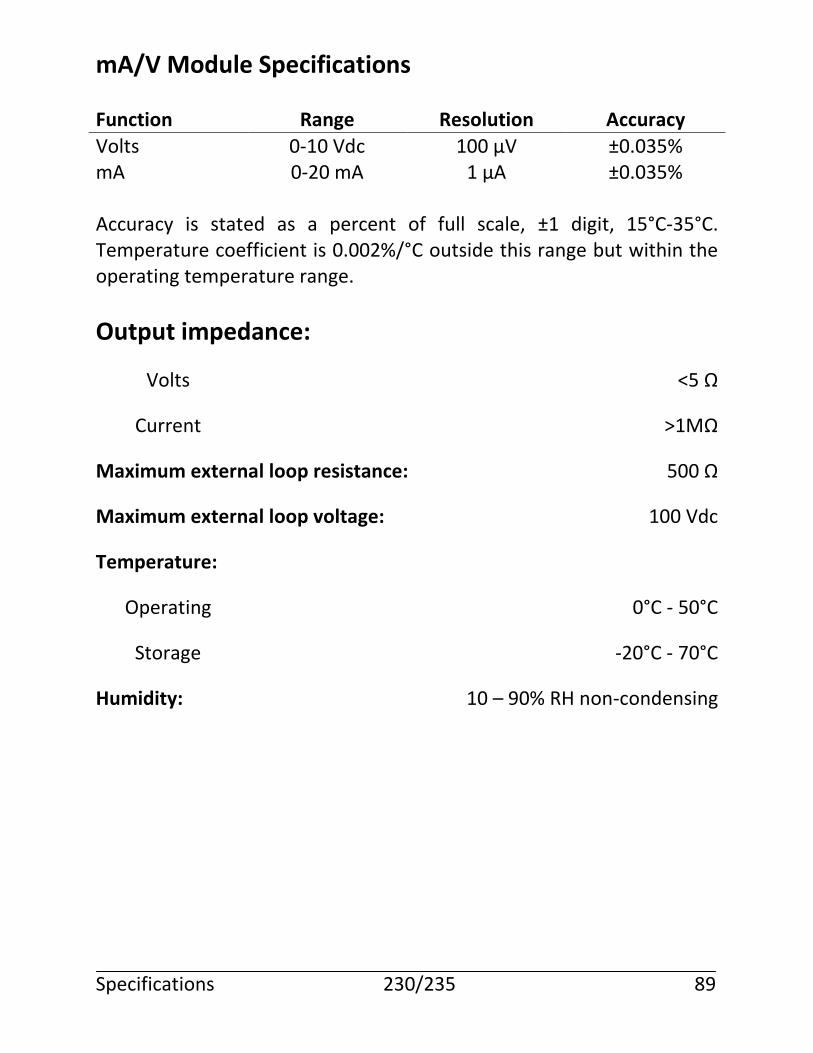
mA/V Module Specifications
Function Range Resolution Accuracy
Volts 0-10 Vdc 100 µV ±0.035% mA 0-20 mA 1 µA ±0.035% Accuracy is stated as a percent of full scale, ±1 digit, 15°C-35°C. Temperature coefficient is 0.002%/°C outside this range but within the operating temperature range.
Output impedance:
Volts <5 Ω
Current >1MΩ
Maximum external loop resistance: 500 Ω
Maximum external loop voltage: 100 Vdc
Temperature:
Operating 0°C - 50°C
Storage -20°C - 70°C
Humidity: 10 – 90% RH non-condensing Specifications 230/235 89
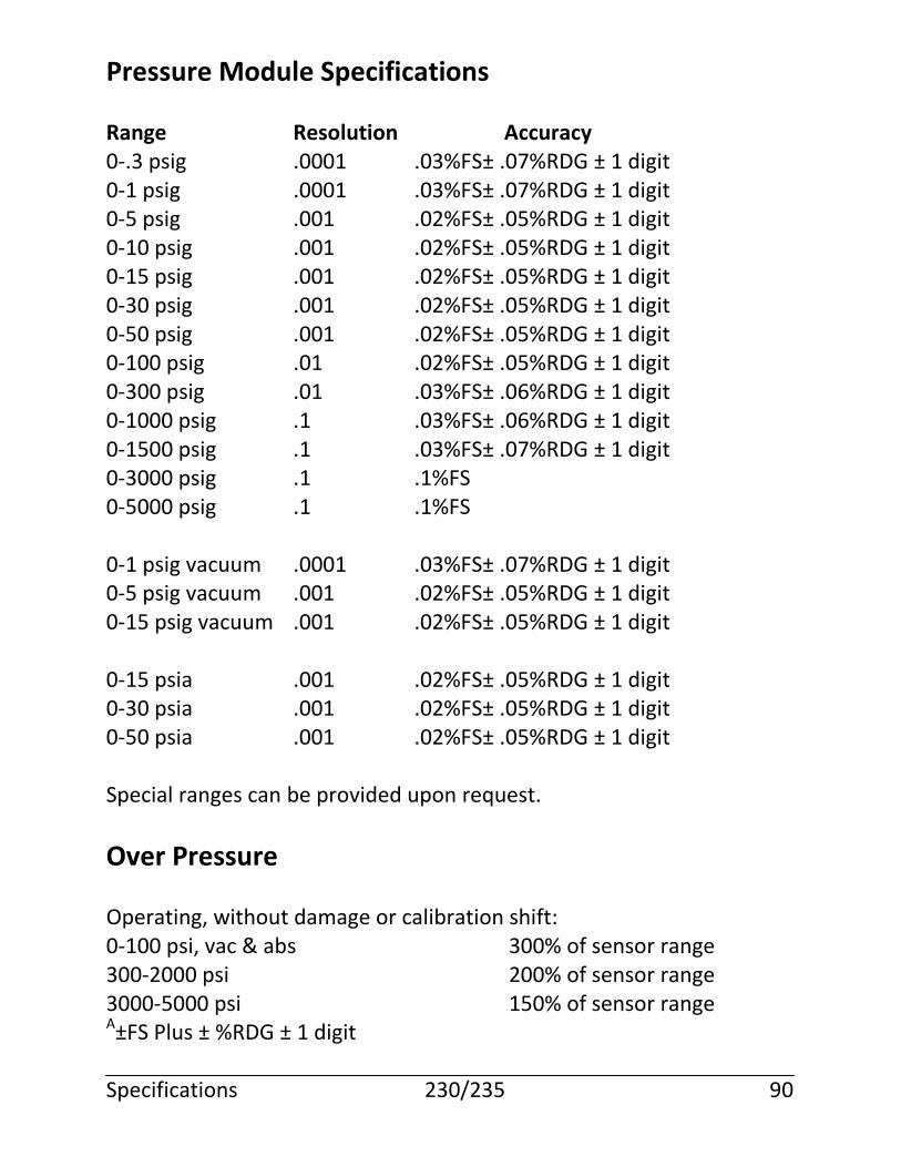
Pressure Module Specifications
Range Resolution Accuracy 0-.3 psig .0001 .03%FS± .07%RDG ± 1 digit 0-1 psig .0001 .03%FS± .07%RDG ± 1 digit 0-5 psig .001 .02%FS± .05%RDG ± 1 digit 0-10 psig .001 .02%FS± .05%RDG ± 1 digit 0-15 psig .001 .02%FS± .05%RDG ± 1 digit 0-30 psig .001 .02%FS± .05%RDG ± 1 digit 0-50 psig .001 .02%FS± .05%RDG ± 1 digit 0-100 psig .01 .02%FS± .05%RDG ± 1 digit 0-300 psig .01 .03%FS± .06%RDG ± 1 digit 0-1000 psig .1 .03%FS± .06%RDG ± 1 digit 0-1500 psig .1 .03%FS± .07%RDG ± 1 digit 0-3000 psig .1 .1%FS 0-5000 psig .1 .1%FS 0-1 psig vacuum .0001 .03%FS± .07%RDG ± 1 digit 0-5 psig vacuum .001 .02%FS± .05%RDG ± 1 digit 0-15 psig vacuum .001 .02%FS± .05%RDG ± 1 digit 0-15 psia .001 .02%FS± .05%RDG ± 1 digit 0-30 psia .001 .02%FS± .05%RDG ± 1 digit 0-50 psia .001 .02%FS± .05%RDG ± 1 digit Special ranges can be provided upon request.
Over Pressure
Operating, without damage or calibration shift: 0-100 psi, vac & abs 300% of sensor range 300-2000 psi 200% of sensor range 3000-5000 psi 150% of sensor range A±FS Plus ± %RDG ± 1 digit Specifications 230/235 90
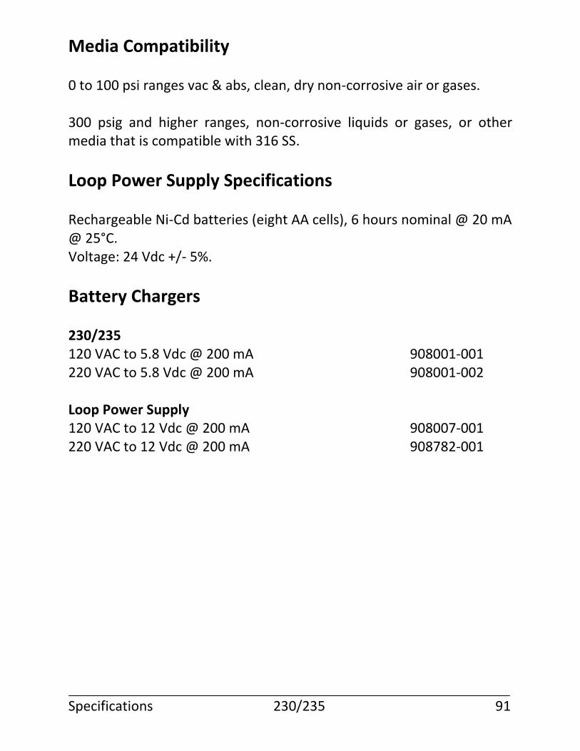
Media Compatibility
0 to 100 psi ranges vac & abs, clean, dry non-corrosive air or gases. 300 psig and higher ranges, non-corrosive liquids or gases, or other media that is compatible with 316 SS.
Loop Power Supply Specifications
Rechargeable Ni-Cd batteries (eight AA cells), 6 hours nominal @ 20 mA @ 25°C. Voltage: 24 Vdc +/- 5%.
Battery Chargers
230/235 120 VAC to 5.8 Vdc @ 200 mA 908001-001 220 VAC to 5.8 Vdc @ 200 mA 908001-002 Loop Power Supply 120 VAC to 12 Vdc @ 200 mA 908007-001 220 VAC to 12 Vdc @ 200 mA 908782-001 Specifications 230/235 91

Notes
Specifications 230/235 92

Notes
Specifications 230/235 93
Notes
Specifications 230/235 94
Index
A
Application Notes, 59-70 Auto Key, 8 Auto Mode, 54
B
BatSave, 20 Battery Charge Time, 88 Charging, 2 Check, 6 Save, 20 Bipolar Frequency Calibration, 55 Bipolar Output, 43
C
Calibration Points Examples, 22 Function, 21 Utilizing, 23 Calibration System Manual Calibration, 16 Pressure Calibration, 14 CE/Zero Key, 8 CJunct, 24 Common Mode Rejection, 88
D
Damp, 28
E
Environmental, 88 Error % Display, 29 Error Messages, 71-73 mA/V Module, 73 External Compensation Module, 31
230/235 I-1
F
Fuse Replacement, 77 Testing, 75 Type, 78
G
General Description, 1 General Specifications, 88
H
Humidity, 88
I
Inc/Dec Key Function, 7 Program, 20 InpRdg, 28 Input Dampen readings, 28 Functions, 32-44 Impedance, 88 Isolation, 88 Milliamps, 32, 82 Millivolts, 32, 82 Ohms, 34 Percent of Scale, 44 Pressure Module, 36 Readings as % of scale, 28 RTD, 34, 84 Selection, 5 Specifications, 82 Thermocouple, 33, 83 Volts, 32, 82 Input Impedance, 88 Introduction, 1-2 230/235 I-2
K
Keys Auto, 8 CE/Zero, 8 Inc/Dec, 7 Option, 9 % Key, 10 Ramp, 10 Setup, 19 SYS Key, 10
L
LCD Vu, 20 Loop Power supply, 57, 70 Specifications, 91 LPS, 57
M
mA/V Module, 54, 66 error messages, 73 Humidity, 89 Loop Resistance, 89 Loop Voltage, 89 Service, 89 Specifications, 89 Temperature, 89 Manual Calibration Using Calibration System, 16 Manufacturing test routines, 27
Menu Selection, 6 Mfg Test, 27 Milliamps, 32 Millivolts Input, 32 Output, 45 Min-Max Mode, 43 mV to Current Converters, 59
Specifications 230/235 I-3
N
Normal Mode Rejection, 88
O
Ohm/RTD Module, 57 Ohms, 34 Simulation, 49, 51
Operation, 3-31 Operator Setup, 19 Option Key, 9 Output Auto Mode, 54 Functions, 45-58 Impedance, 88 Isolation, 88 mA/Volt Module, 54 Millivolts, 45-46, 85 Ohms, 85 Ramp Function, 52 RTD, 87 RTD/OHMS, 49 Selection, 5 Thermocouple, 46, 86 Volts, 45, 85 Output Impedance, 88 mA/V Module, 89 Output Specifications, 85 Owner Enter name, 25
P
Pause Time, 27 % Error Display, 29 % Key, 10 Percent of Scale, 23, 44 Power On Sequence, 3 Pressure Calibration Using Calibration System, 14
230/235 I-4
Pressure Module, 68-69 Description, 36 Disconnected, 40 Electrical Connection, 36 Media Compatibility, 37, 91 Over Pressure, 90 Pressure Connection, 36 Safety, 41 Zeroing a gauge, 39 Zeroing an absolute, 40
R
Ramp, 64
Ramp Function, 52 Ramp Key, 10 Return Authorization, 74 RTD, 34 3-wire Platinum, 63 Simulation, 49 RTD to 2-Wire Transmitter, 62
S
Save Setup values, 28 Serial Interface, 27 SerIf, 27 Service Information, 74-81 Setup, 19 Enter owner’s name, 25 Save values, 28 Specifications, 82-91 Temperature, 88 SYS Key, 10 230/235 I-5
T
Temperature Operating, 88 Storage, 88 Temperature Compensation Module, 31 Thermocouple, 33 Cold/Reference Junction compensation, 24 Simulation, 46 2-wire Transmitter, 60-61 Trip Detect, 41, 64
U
Unit on Time, 88
V
Viewing Angle, 20 Volts Input, 32 Output, 45 230/235 I-6
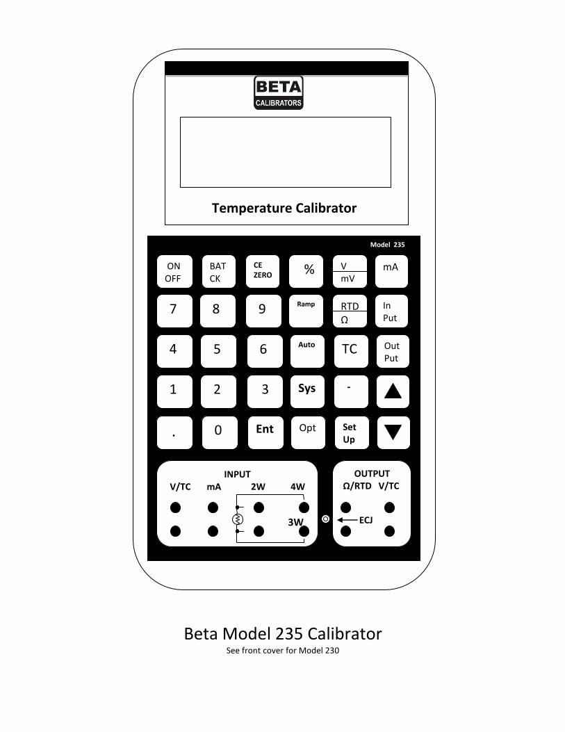
Beta Model 235 Calibrator
See front cover for Model 230
Temperature Calibrator
Model 235
ON OFF
BAT CK
CE ZERO % V
mV mA
7
4
1
.
8 9 Ramp RTD Ω
In Put
5 6 Auto TC Out Put
2 3 Sys -
0 Ent Opt Set Up
INPUT V/TC mA 2W 4W
3W
OUTPUT Ω/RTD V/TC
ECJ