MOBIUS Water Heater Gas Fired, Instantaneous, Tankless Water Heater
38
MOBIUS Water Heater Takagi Industrial Co. USA, Inc. Installation and Operation Instruction MODEL T - M1 MOBIUS Water Heater Gas Fired, Instantaneous, Tankless Water Heater Store these instructions near to the water heater for reference purposes. TAKAGI INDUSTRIAL CO. USA Inc. 6 Goddard, Irvine, CA 92618 Tel. (949) 453 - 8388, FAX. (949) 453-8498 E-Mail: [email protected] http://www.takagi-usa.com FEATURES θ ENDLESS HOT WATER SUPPLY θ ON-DEMAND HEATING θ PILOT-LESS SYSTEM θ COMPACT, SPACE SAVING θ COMPUTERIZED CONTROLS θ COMPUTERIZED SAFETY DEVICES θ MULTI-UNIT INSTALLATION READY
Transcript of MOBIUS Water Heater Gas Fired, Instantaneous, Tankless Water Heater
MOBIUS Water Heater Takagi Industrial Co. USA, Inc.
Installation and Operation Instruction
MODEL T - M1
MOBIUS Water Heater
Gas Fired, Instantaneous, Tankless Water Heater
Store these instructions near to the water heater for reference purposes.
TAKAGI INDUSTRIAL CO. USA Inc.6 Goddard, Irvine, CA 92618
Tel. (949) 453 - 8388, FAX. (949) 453-8498E-Mail: [email protected]
http://www.takagi-usa.com
FEATURES θ ENDLESS HOT WATER SUPPLY θ ON-DEMAND HEATING θ PILOT-LESS SYSTEM θ COMPACT, SPACE SAVING θ COMPUTERIZED CONTROLS θ COMPUTERIZED SAFETY DEVICES θ MULTI-UNIT INSTALLATION READY
FOR YOUR SAFETY - READ BEFORE OPERATING
FOR YOUR SAFETY - This product must be installed and serviced by a professional Plumbing or Gas licensed service-trained technician. Installation and/or operation could create carbon monoxide gas and other dangerous gases, which can cause serious injury or death. Improper installation and/or operation will void the warranty.
WARNING: If the information in this manual is not followed exactly, a fire or explosion may result, causing property damage, personal injury or death. • Do not store or use gasoline or other flammable vapors and liquids in the vicinity of
this or any other appliance. • WHAT TO DO IF YOU SMELL GAS
• Do not try light any appliance. • Do not touch any electrical switch. Do not use any phone in your building. • Immediately call your gas supplier from a neighbor’s phone. Follow the gas
supplier’s instructions. • If you cannot reach your gas supplier, call the fire department.
• A trained technician, qualified installer, or service agency, must perform installation
and service.
WARNING: To install this unit correctly, you must follow the procedures in this manual. If you do not do this, the warranty offered by Takagi Industrial Co. USA, Inc. will be voided. Do not make any changes to the water heater, or to its gas controls, gas orifices, wiring or draft. Any modifications may void the warranty. If the unit must be modified because of special conditions, talk with a factory representative before beginning anychanges.
CONTENTS
Introduction …………. 4 For Your Safety …………. 4 Operation …………. 6 • General …………. 6 • Temperature …………. 7 • Freeze Prevent Device …………. 7 • Winterizing …………. 7 Installation …………. 8 • General Instruction …………. 8 • Outdoor Installation …………. 9 • Indoor Installation …………. 11 • Combustible Air Supply …………..11 • Venting Instructions …………..12 • Vent Connections …………..12 • Vent Termination …………..13 • Gas Supply and pipe …………. 14 • Water Connections …………. 15 • T & P Relief Valve …………. 16 • Electrical Connection …………. 17 • Wiring …………. 18 • Starting The System …………. 19 Operating Instructions …………..19 Maintenance and Service …………. 24 Cleaning the Heat Exchanger ……… 25 Trouble Shooting …………. 25 Trouble Shooting Flow Chart……….. 26 Part Diagram …………. 30 Part List …………. 34 MOBIUS Water Heater Application….36 Temperature Chart …………. 38
SPECIFICATIONS
Natural Gas Input Min. 25,000 Btu Max. 235,000 Btu LPG Input Min. 25,000 Btu Max. 225,000 Btu Gas Connection ¾” NPT Water Connection ¾” NPT Water Pressure Min. 15 psi Max. 150 psi Natural Gas Pressure Inlet Min. 5” WC Max. 10.5” WC LP Gas Pressure Inlet Min. 11” WC Max. 14” WC Manifold Pressure Natural 2.2” WC Propane 2.7” WC Weight 70 lbs. Dimensions 24”x18”x 9” Ignition Electronic Ignition Electrical Supply AC 120 V
*** • Inlet gas pressure must be within above value. • High altitude, before install in areas over 4,500 feet above sea level. Contact the
manufacturer for a high altitude. • Check the rating plate to insure this product matches your specifications. • Takagi - USA is constantly improving our products, therefore specifications are subject to
change without prior notice.
INTRODUCTION
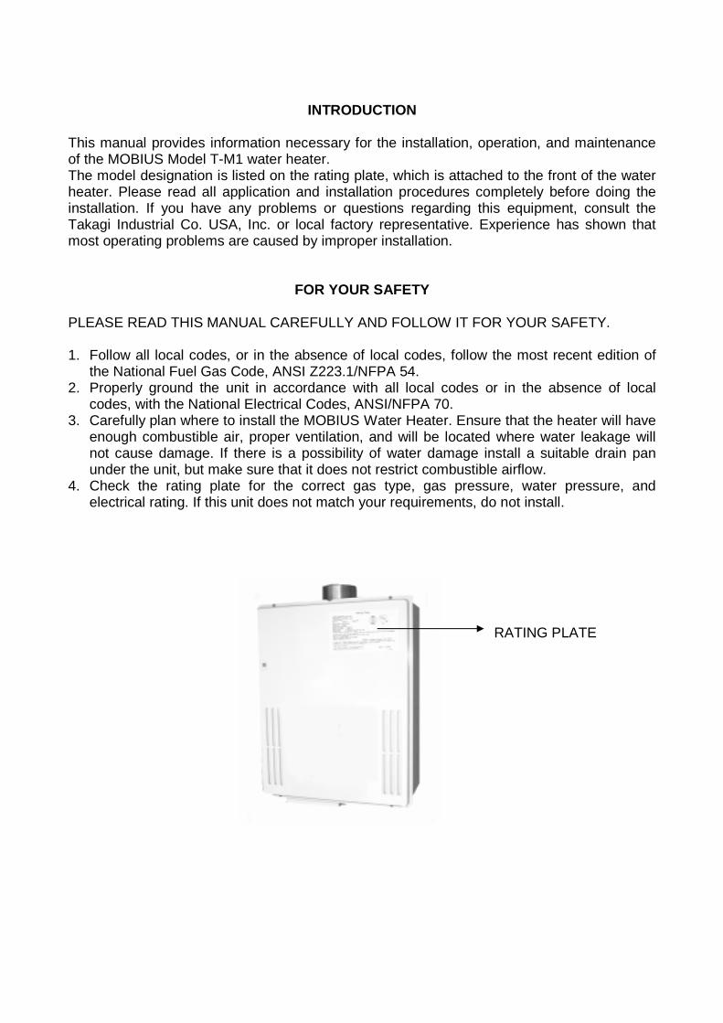
This manual provides information necessary for the installation, operation, and maintenance of the MOBIUS Model T-M1 water heater. The model designation is listed on the rating plate, which is attached to the front of the water heater. Please read all application and installation procedures completely before doing the installation. If you have any problems or questions regarding this equipment, consult the Takagi Industrial Co. USA, Inc. or local factory representative. Experience has shown that most operating problems are caused by improper installation.
FOR YOUR SAFETY
PLEASE READ THIS MANUAL CAREFULLY AND FOLLOW IT FOR YOUR SAFETY. 1. Follow all local codes, or in the absence of local codes, follow the most recent edition of
the National Fuel Gas Code, ANSI Z223.1/NFPA 54. 2. Properly ground the unit in accordance with all local codes or in the absence of local
codes, with the National Electrical Codes, ANSI/NFPA 70. 3. Carefully plan where to install the MOBIUS Water Heater. Ensure that the heater will have
enough combustible air, proper ventilation, and will be located where water leakage will not cause damage. If there is a possibility of water damage install a suitable drain pan under the unit, but make sure that it does not restrict combustible airflow.
4. Check the rating plate for the correct gas type, gas pressure, water pressure, and electrical rating. If this unit does not match your requirements, do not install.
RATING PLATE
5. If any problem should occur, turn off all hot water taps and turn off the gas. Call a trained technician, the Gas Company, or the manufacturer.
6. WARNING: Do not disconnect the electrical supply if the ambient temperatures will be
near freezing. The Freeze Prevention Device will only work if the unit has proper electrical power. The Freeze Prevention Device is rated for temperatures down to 5ºF (-15ºC) in a wind free environment. Wind chill factor can cause the MOBIUS Water Heater to freeze and be damaged at temperatures above 5ºF (-15ºC). Refer to the section on Winterizing and the Freeze Prevention Device for more information. Weather related damage to the heat exchanger will not be covered under the warranty.
7. WARNING: Before bathing or showering always check the water temperature. Do not leave children or the infirm without supervision in a shower or bath. The water temperature is factory set at 140ºF (60ºC) to maximize the amount of hot water available without an optional temperature remote controller. Water temperatures over 125ºF can cause severe burns instantly, or death from scalds.
8. WARNING: Do not use this appliance if any part has been underwater. Immediately call a certified and trained technician to inspect and service the unit if necessary.
9. WARNING: Do not store or use gasoline or other flammable vapors and liquids in the vicinity of this or any other appliance.
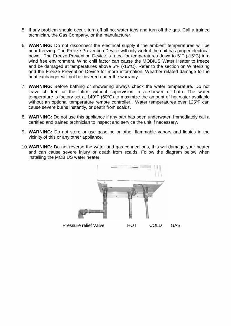
10. WARNING: Do not reverse the water and gas connections, this will damage your heater and can cause severe injury or death from scalds. Follow the diagram below when installing the MOBIUS water heater.
Pressure relief Valve HOT COLD GAS
OPERATION
GENERAL
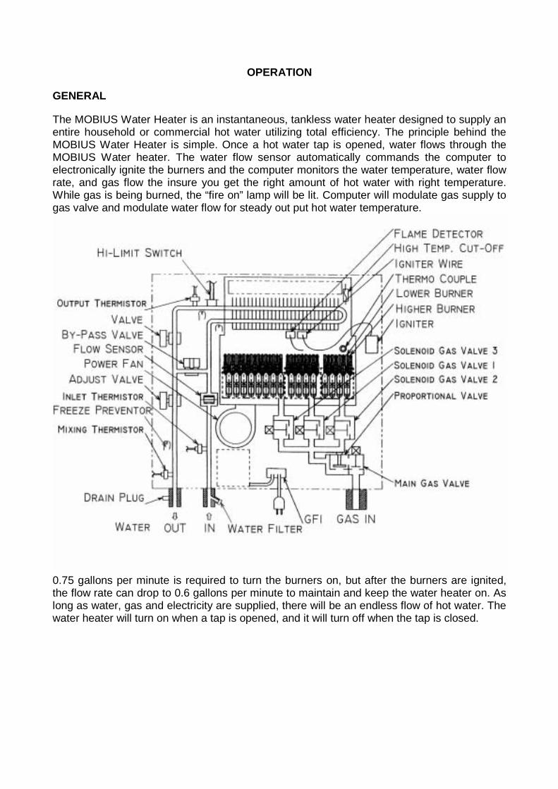
The MOBIUS Water Heater is an instantaneous, tankless water heater designed to supply an entire household or commercial hot water utilizing total efficiency. The principle behind the MOBIUS Water Heater is simple. Once a hot water tap is opened, water flows through the MOBIUS Water heater. The water flow sensor automatically commands the computer to electronically ignite the burners and the computer monitors the water temperature, water flow rate, and gas flow the insure you get the right amount of hot water with right temperature. While gas is being burned, the “fire on” lamp will be lit. Computer will modulate gas supply to gas valve and modulate water flow for steady out put hot water temperature.
0.75 gallons per minute is required to turn the burners on, but after the burners are ignited, the flow rate can drop to 0.6 gallons per minute to maintain and keep the water heater on. As long as water, gas and electricity are supplied, there will be an endless flow of hot water. The water heater will turn on when a tap is opened, and it will turn off when the tap is closed.
Temperature
The water temperature has been set on the computer by the factory to be Maximum 140º F (60º C). In order to achieve lower water temperatures, cold water needs to be mixed in with the hot, or an optional part No. TM-RE10 can be installed allowing manual adjustment of the output temperature for lower or higher. WARNING: Temperatures above 125º F (52º C) can cause severe burns or death from scalding. Children, disabled and the elderly are at high risk of being injured. Feel the water temperature before bathing or showering. Do not leave children, disabled, and the elderly without supervision. MOBIUS water heater will produce a flow rate of hot water that is depend on the inlet water temperature and the setting on the TM-RE10. Refer to the flow vs. temperature chart for the output capabilities end of this installation manual. Freeze Prevention Devices This unit comes equipped with heaters that discourage the unit from freezing, but for this freeze prevention system to operate there has to be electrical power to the unit. The freeze prevention devices will not work if the electrical power source is disconnected. The unit has been rated for temperatures down to 5º F (-15º C) in a wind free environment. A wind chill factor will cause the unit to freeze at temperatures above 5º F (-15º C). Do not install the water heater in an area with extremely cold weather. This will void your warranty and Takagi - USA will not be responsible for any damage that occurs. CAUTION: The pipe heaters are located on the MOBIUS Water Heater only. Any hot or cold water pipes located outside of the unit will not be protected. Properly protect and insulate these pipes from freezing.
Winterizing
If the heater will not be used for a long period of time or if the temperatures will drop below 5º F (-15º C) with the wind chill factor, turn off the heater and drain the unit of water. This will keep it from freezing and being damaged. Follow these instructions carefully: 1. Turn off the power supply to the MOBIUS Water Heater. 2. Close the manual gas control valve located outside your heater. 3. Close the manual water shut off valve located on the water supply line. 4. Open all hot water taps in the house. (Bathroom, kitchen, laundry room, etc.). When the
water flow has ceased, close all hot water taps. 5. Have a bucket or pan available to catch the water as it drains from the T-M1 drain plugs.
Remove the drain plugs to drain all the water out of the unit. 6. Let sit for 5 minutes. 7. Securely screw the drain plugs back into place. To restart heater, follow these steps: 1. Make sure all hot water taps are closed and the drain plugs are securely attached. 2. Purge the water line of debris. 3. Turn on the manual water control valve located on the water supply line. 4. Open all the hot water taps to verify water flows to the taps. Then close hot water taps.
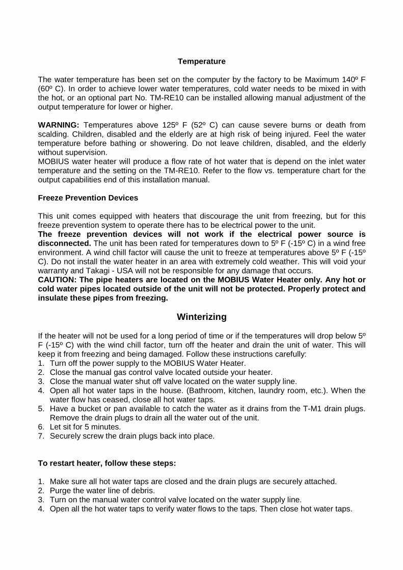
5. Turn on the manual gas control valve located on the gas supply line. 6. Turn on the power supply to the MOBIUS Water Heater.
DRAIN DRAIN AND FILTER
INSTALLATION
General All gas water heaters require careful and correct installation to insure safe and efficient operation. This manual must be followed exactly. 1. Read the For Your Safety section in the beginning of this manual. 2. The regulator is preset at the factory. It is computer controlled and should not need
adjustment. 3. Maintain proper space for servicing. Install the unit so that it can be connected or removed
easily. 4. The electrical connection requires a means for switching off the power supply. 5. Avoid installing the unit in an area with high levels of dust, sand or debris. These particles
may clog the air vent or impair the function of the fan, leading to improper combustion. Regular maintenance is needed in these environments.
6. Do not install the unit where the exhaust vent is pointing into any opening in a building or where the noise may disturb neighbors.
Accessories Check that all parts listed below were included with the unit. Installation Manual, Warranty Card and Optional Part Information
This section is for the installer. The installer is responsible for the correct installation of the MOBIUS Water Heater. For Your Safety: Only a certified and trained service technician or qualified plumber may service or install your product.
OUTDOOR INSTALLATION
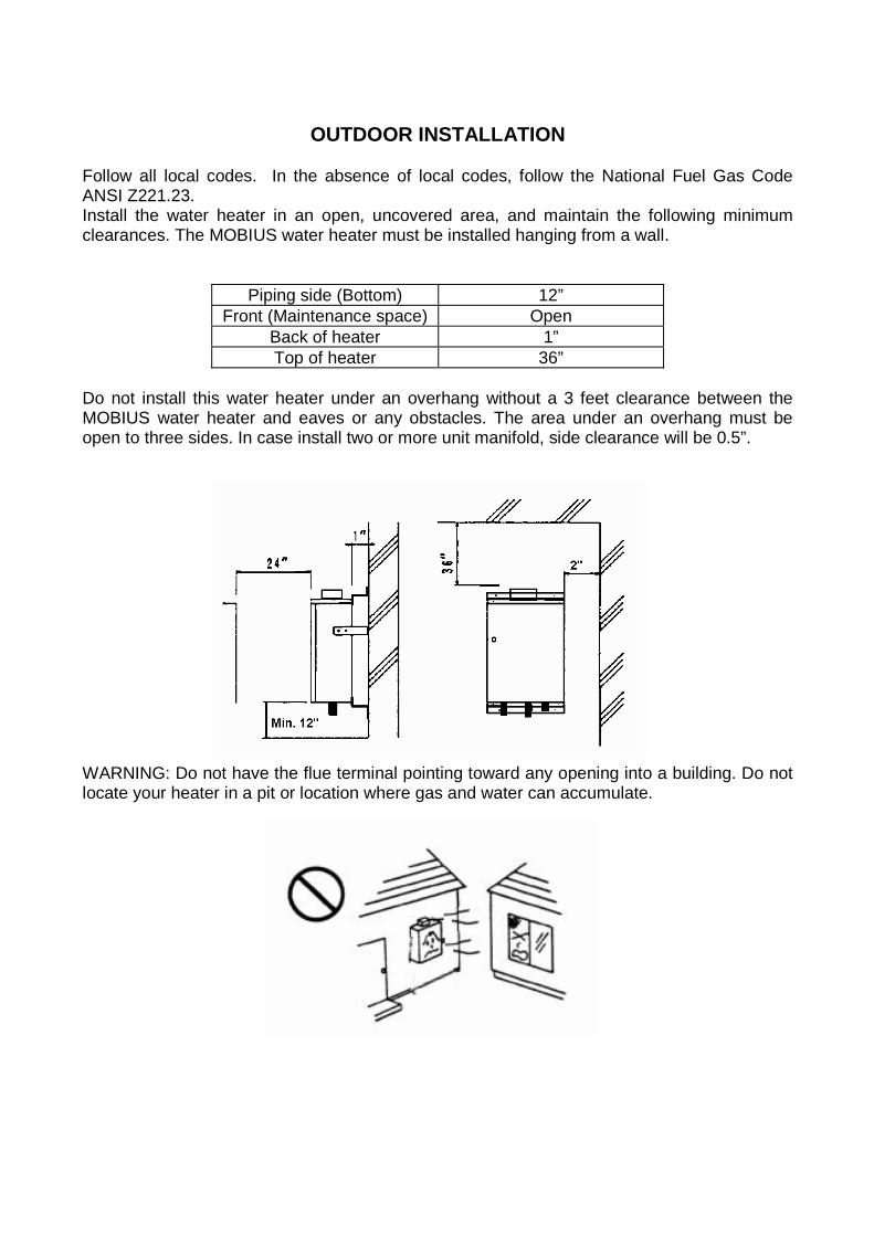
Follow all local codes. In the absence of local codes, follow the National Fuel Gas Code ANSI Z221.23. Install the water heater in an open, uncovered area, and maintain the following minimum clearances. The MOBIUS water heater must be installed hanging from a wall.
Piping side (Bottom) 12” Front (Maintenance space) Open
Back of heater 1” Top of heater 36”
Do not install this water heater under an overhang without a 3 feet clearance between the MOBIUS water heater and eaves or any obstacles. The area under an overhang must be open to three sides. In case install two or more unit manifold, side clearance will be 0.5”.
WARNING: Do not have the flue terminal pointing toward any opening into a building. Do not locate your heater in a pit or location where gas and water can accumulate.
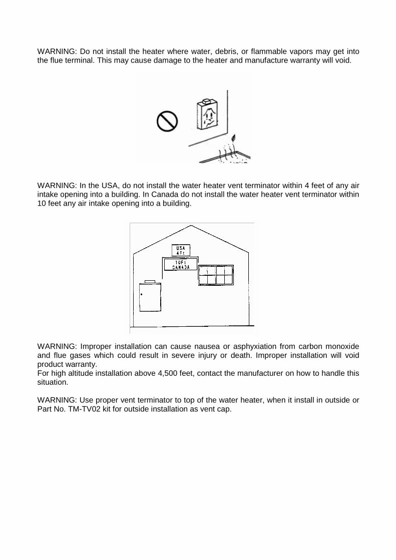
WARNING: Do not install the heater where water, debris, or flammable vapors may get into the flue terminal. This may cause damage to the heater and manufacture warranty will void.
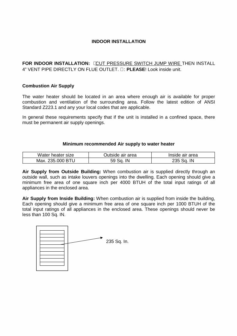
WARNING: In the USA, do not install the water heater vent terminator within 4 feet of any air intake opening into a building. In Canada do not install the water heater vent terminator within 10 feet any air intake opening into a building.
WARNING: Improper installation can cause nausea or asphyxiation from carbon monoxide and flue gases which could result in severe injury or death. Improper installation will void product warranty. For high altitude installation above 4,500 feet, contact the manufacturer on how to handle this situation. WARNING: Use proper vent terminator to top of the water heater, when it install in outside or Part No. TM-TV02 kit for outside installation as vent cap.
INDOOR INSTALLATION FOR INDOOR INSTALLATION: ∗ CUT PRESSURE SWITCH JUMP WIRE THEN INSTALL 4” VENT PIPE DIRECTLY ON FLUE OUTLET. ∗ : PLEASE! Look inside unit. Combustion Air Supply The water heater should be located in an area where enough air is available for proper combustion and ventilation of the surrounding area. Follow the latest edition of ANSI Standard Z223.1 and any your local codes that are applicable. In general these requirements specify that if the unit is installed in a confined space, there must be permanent air supply openings.
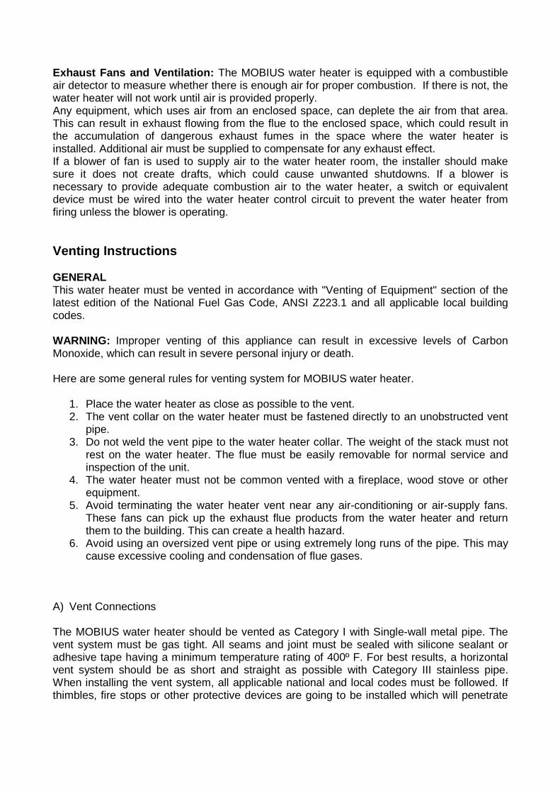
Minimum recommended Air supply to water heater
Water heater size Outside air area Inside air area Max. 235.000 BTU 59 Sq. IN 235 Sq. IN
Air Supply from Outside Building: When combustion air is supplied directly through an outside wall, such as intake louvers openings into the dwelling. Each opening should give a minimum free area of one square inch per 4000 BTUH of the total input ratings of all appliances in the enclosed area. Air Supply from Inside Building: When combustion air is supplied from inside the building, Each opening should give a minimum free area of one square inch per 1000 BTUH of the total input ratings of all appliances in the enclosed area. These openings should never be less than 100 Sq. IN. 235 Sq. In.
Exhaust Fans and Ventilation: The MOBIUS water heater is equipped with a combustible air detector to measure whether there is enough air for proper combustion. If there is not, the water heater will not work until air is provided properly. Any equipment, which uses air from an enclosed space, can deplete the air from that area. This can result in exhaust flowing from the flue to the enclosed space, which could result in the accumulation of dangerous exhaust fumes in the space where the water heater is installed. Additional air must be supplied to compensate for any exhaust effect. If a blower of fan is used to supply air to the water heater room, the installer should make sure it does not create drafts, which could cause unwanted shutdowns. If a blower is necessary to provide adequate combustion air to the water heater, a switch or equivalent device must be wired into the water heater control circuit to prevent the water heater from firing unless the blower is operating. Venting Instructions GENERAL This water heater must be vented in accordance with "Venting of Equipment" section of the latest edition of the National Fuel Gas Code, ANSI Z223.1 and all applicable local building codes. WARNING: Improper venting of this appliance can result in excessive levels of Carbon Monoxide, which can result in severe personal injury or death. Here are some general rules for venting system for MOBIUS water heater.
1. Place the water heater as close as possible to the vent. 2. The vent collar on the water heater must be fastened directly to an unobstructed vent
pipe. 3. Do not weld the vent pipe to the water heater collar. The weight of the stack must not
rest on the water heater. The flue must be easily removable for normal service and inspection of the unit.
4. The water heater must not be common vented with a fireplace, wood stove or other equipment.
5. Avoid terminating the water heater vent near any air-conditioning or air-supply fans. These fans can pick up the exhaust flue products from the water heater and return them to the building. This can create a health hazard.
6. Avoid using an oversized vent pipe or using extremely long runs of the pipe. This may cause excessive cooling and condensation of flue gases.
A) Vent Connections The MOBIUS water heater should be vented as Category I with Single-wall metal pipe. The vent system must be gas tight. All seams and joint must be sealed with silicone sealant or adhesive tape having a minimum temperature rating of 400º F. For best results, a horizontal vent system should be as short and straight as possible with Category III stainless pipe. When installing the vent system, all applicable national and local codes must be followed. If thimbles, fire stops or other protective devices are going to be installed which will penetrate
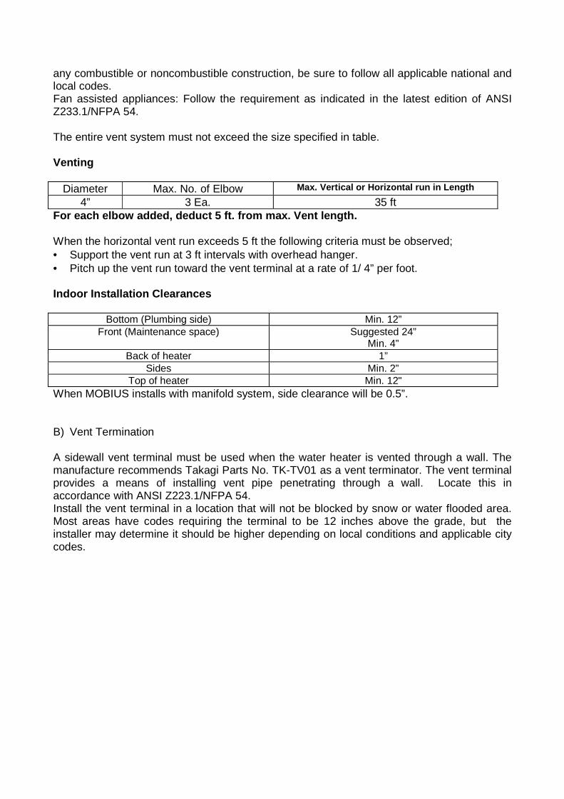
any combustible or noncombustible construction, be sure to follow all applicable national and local codes. Fan assisted appliances: Follow the requirement as indicated in the latest edition of ANSI Z233.1/NFPA 54. The entire vent system must not exceed the size specified in table. Venting
Diameter Max. No. of Elbow Max. Vertical or Horizontal run in Length 4” 3 Ea. 35 ft
For each elbow added, deduct 5 ft. from max. Vent length. When the horizontal vent run exceeds 5 ft the following criteria must be observed; • Support the vent run at 3 ft intervals with overhead hanger. • Pitch up the vent run toward the vent terminal at a rate of 1/ 4” per foot. Indoor Installation Clearances
Bottom (Plumbing side) Min. 12” Front (Maintenance space) Suggested 24”
Min. 4” Back of heater 1”
Sides Min. 2” Top of heater Min. 12"
When MOBIUS installs with manifold system, side clearance will be 0.5”. B) Vent Termination A sidewall vent terminal must be used when the water heater is vented through a wall. The manufacture recommends Takagi Parts No. TK-TV01 as a vent terminator. The vent terminal provides a means of installing vent pipe penetrating through a wall. Locate this in accordance with ANSI Z223.1/NFPA 54. Install the vent terminal in a location that will not be blocked by snow or water flooded area. Most areas have codes requiring the terminal to be 12 inches above the grade, but the installer may determine it should be higher depending on local conditions and applicable city codes.
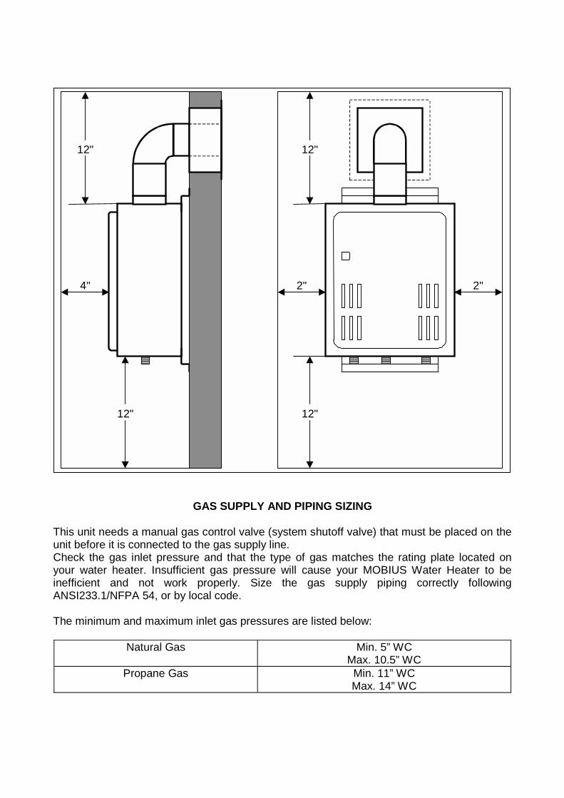
GAS SUPPLY AND PIPING SIZING
This unit needs a manual gas control valve (system shutoff valve) that must be placed on the unit before it is connected to the gas supply line. Check the gas inlet pressure and that the type of gas matches the rating plate located on your water heater. Insufficient gas pressure will cause your MOBIUS Water Heater to be inefficient and not work properly. Size the gas supply piping correctly following ANSI233.1/NFPA 54, or by local code. The minimum and maximum inlet gas pressures are listed below:
Natural Gas Min. 5” WC Max. 10.5” WC
Propane Gas Min. 11” WC Max. 14” WC
12"
12"
4"
12"
12"
2" 2"
In order to get a correct reading of the inlet supply pressure, the water heater and all other gas appliances sharing the gas supply line must be firing at maximum capacity when the pressure is measured. Maximum gas pressures must not exceed this value. If the gas pressure is insufficient, this may be the result of an undersized gas supply pipe. The MOBIUS water heater will not perform to its maximum capabilities without enough gas supply. After connecting the unit, check for gas leaks by applying soapy water to all gas fittings and connections. Soap bubbles are a sign of gas leaks. This appliance and its individual shut-off valve must be isolated from the gas supply piping system by unplugging the unit and turning off the main gas valve during any pressure testing of the gas supply piping system at test pressures equal to or less than ½ Psi. The appliance and its gas connections must be leak tested before placing the unit in operation. Always use approved connectors to connect the unit to the gas line. Always purge the gas line of any debris before connection to the heater. WARNING: Conversion of this unit from natural gas to propane or propane to natural gas cannot be done in the field. Contact your local retailer or distributor to get the correct unit for your gas type.
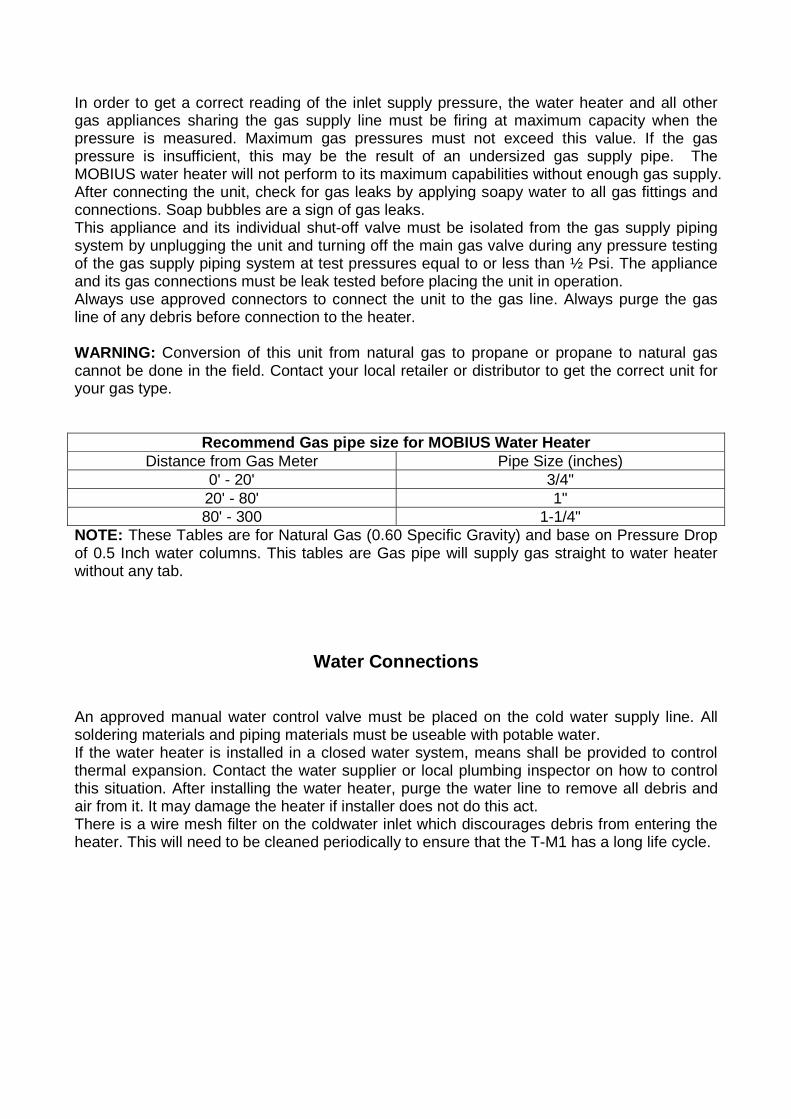
Recommend Gas pipe size for MOBIUS Water Heater Distance from Gas Meter Pipe Size (inches)
0' - 20' 3/4" 20' - 80' 1" 80' - 300 1-1/4"
NOTE: These Tables are for Natural Gas (0.60 Specific Gravity) and base on Pressure Drop of 0.5 Inch water columns. This tables are Gas pipe will supply gas straight to water heater without any tab.
Water Connections
An approved manual water control valve must be placed on the cold water supply line. All soldering materials and piping materials must be useable with potable water. If the water heater is installed in a closed water system, means shall be provided to control thermal expansion. Contact the water supplier or local plumbing inspector on how to control this situation. After installing the water heater, purge the water line to remove all debris and air from it. It may damage the heater if installer does not do this act. There is a wire mesh filter on the coldwater inlet which discourages debris from entering the heater. This will need to be cleaned periodically to ensure that the T-M1 has a long life cycle.
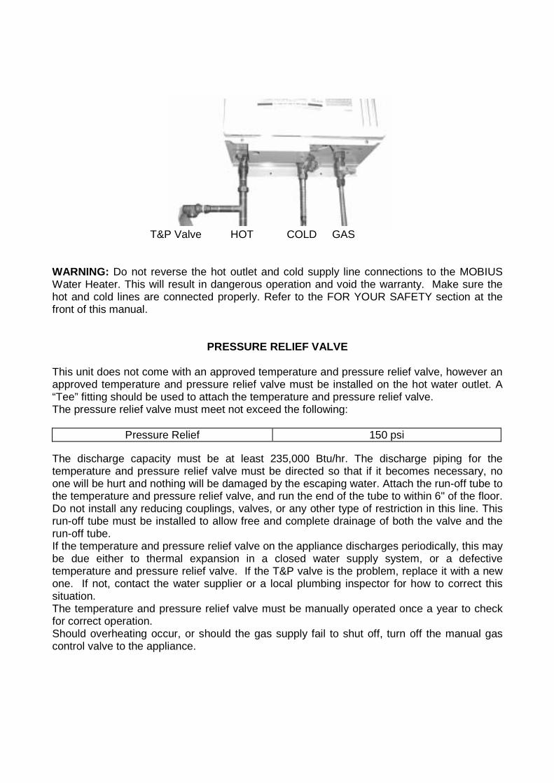
T&P Valve HOT COLD GAS
WARNING: Do not reverse the hot outlet and cold supply line connections to the MOBIUS Water Heater. This will result in dangerous operation and void the warranty. Make sure the hot and cold lines are connected properly. Refer to the FOR YOUR SAFETY section at the front of this manual.
PRESSURE RELIEF VALVE
This unit does not come with an approved temperature and pressure relief valve, however an approved temperature and pressure relief valve must be installed on the hot water outlet. A “Tee” fitting should be used to attach the temperature and pressure relief valve. The pressure relief valve must meet not exceed the following:
Pressure Relief 150 psi The discharge capacity must be at least 235,000 Btu/hr. The discharge piping for the temperature and pressure relief valve must be directed so that if it becomes necessary, no one will be hurt and nothing will be damaged by the escaping water. Attach the run-off tube to the temperature and pressure relief valve, and run the end of the tube to within 6" of the floor. Do not install any reducing couplings, valves, or any other type of restriction in this line. This run-off tube must be installed to allow free and complete drainage of both the valve and the run-off tube. If the temperature and pressure relief valve on the appliance discharges periodically, this may be due either to thermal expansion in a closed water supply system, or a defective temperature and pressure relief valve. If the T&P valve is the problem, replace it with a new one. If not, contact the water supplier or a local plumbing inspector for how to correct this situation. The temperature and pressure relief valve must be manually operated once a year to check for correct operation. Should overheating occur, or should the gas supply fail to shut off, turn off the manual gas control valve to the appliance.
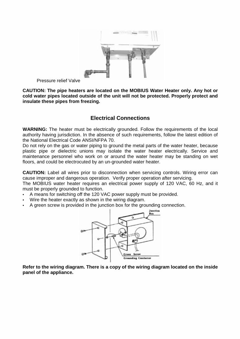
Pressure relief Valve
CAUTION: The pipe heaters are located on the MOBIUS Water Heater only. Any hot or cold water pipes located outside of the unit will not be protected. Properly protect and insulate these pipes from freezing.
Electrical Connections
WARNING: The heater must be electrically grounded. Follow the requirements of the local authority having jurisdiction. In the absence of such requirements, follow the latest edition of the National Electrical Code ANSI/NFPA 70. Do not rely on the gas or water piping to ground the metal parts of the water heater, because plastic pipe or dielectric unions may isolate the water heater electrically. Service and maintenance personnel who work on or around the water heater may be standing on wet floors, and could be electrocuted by an un-grounded water heater. CAUTION: Label all wires prior to disconnection when servicing controls. Wiring error can cause improper and dangerous operation. Verify proper operation after servicing. The MOBIUS water heater requires an electrical power supply of 120 VAC, 60 Hz, and it must be properly grounded to function. • A means for switching off the 120 VAC power supply must be provided. • Wire the heater exactly as shown in the wiring diagram. • A green screw is provided in the junction box for the grounding connection.
Refer to the wiring diagram. There is a copy of the wiring diagram located on the inside panel of the appliance.
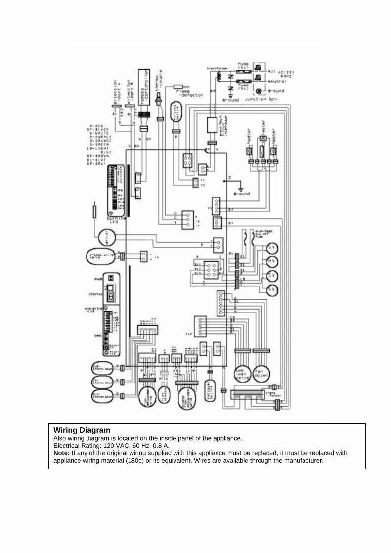
Wiring Diagram Also wiring diagram is located on the inside panel of the appliance. Electrical Rating: 120 VAC, 60 Hz, 0.8 A. Note: If any of the original wiring supplied with this appliance must be replaced, it must be replaced with appliance wiring material (180c) or its equivalent. Wires are available through the manufacturer.
STARTING THE SYSTEM
For your safety, read before operating. a) This water heater does not have a pilot. It is equipped with an ignition device, which
automatically lights the burner. Do not try to light the burner by hand. b) Before operating, make sure that a gas leak is not evident by smelling the area around the
T-M1. Be sure to smell next to the floor because some gas is heavier than air and will settle on the floor.
c) Use only a hand to turn the gas valve knob. Never use tools. If the knob will not turn by hand, do not try to repair it, call qualified service technician. Force or attempted repair may result in a fire or explosion due to the gas leakage.
d) Do not use this water heater if any part has been under water. Immediately call a qualified service technician to inspect the water heater and to replace any parts that have been under water.
WHAT TO DO IF YOU SMELL GAS • Do not try to start the water heater. • Do not touch any electrical switches, and do not use any phone in your building. • Immediately call the gas supplier from somewhere else. Follow the gas supplier’s
instructions. • If you cannot reach the gas supplier, call the fire department. Operating Instructions The MOBIUS Water Heater is an instantaneous, tankless water heater designed to supply your entire household and commercial hot water needs utilizing total efficiency. The principle behind the MOBIUS Water Heater is simple. Once you open a hot water tap, water flows through the MOBIUS Water heater. The water flow sensor automatically commands the computer to electronically ignite the burners and the computer monitors the water temperature, water flow rate, and gas flow the insure you get the right amount of hot water with right temperature hot water. After the burners are ignited the “fire on” lamp is lit. Computer will modulate gas supply to valve and water flow. 0.75 gallons per minute is required to turn the burners on, after the burners are ignited, the flow rate can be lowered to 0.6 gallons per minute to maintain and still keep the heater on. Now as long as you have water, gas and electricity, you will get an endless hot water. Open a hot water tap to turn on your water heater. Close the hot water tap to turn off your water heater.
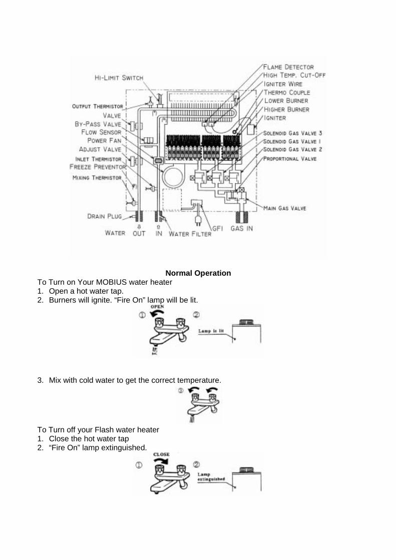
Normal Operation To Turn on Your MOBIUS water heater 1. Open a hot water tap. 2. Burners will ignite. “Fire On” lamp will be lit.
3. Mix with cold water to get the correct temperature.
To Turn off your Flash water heater 1. Close the hot water tap 2. “Fire On” lamp extinguished.
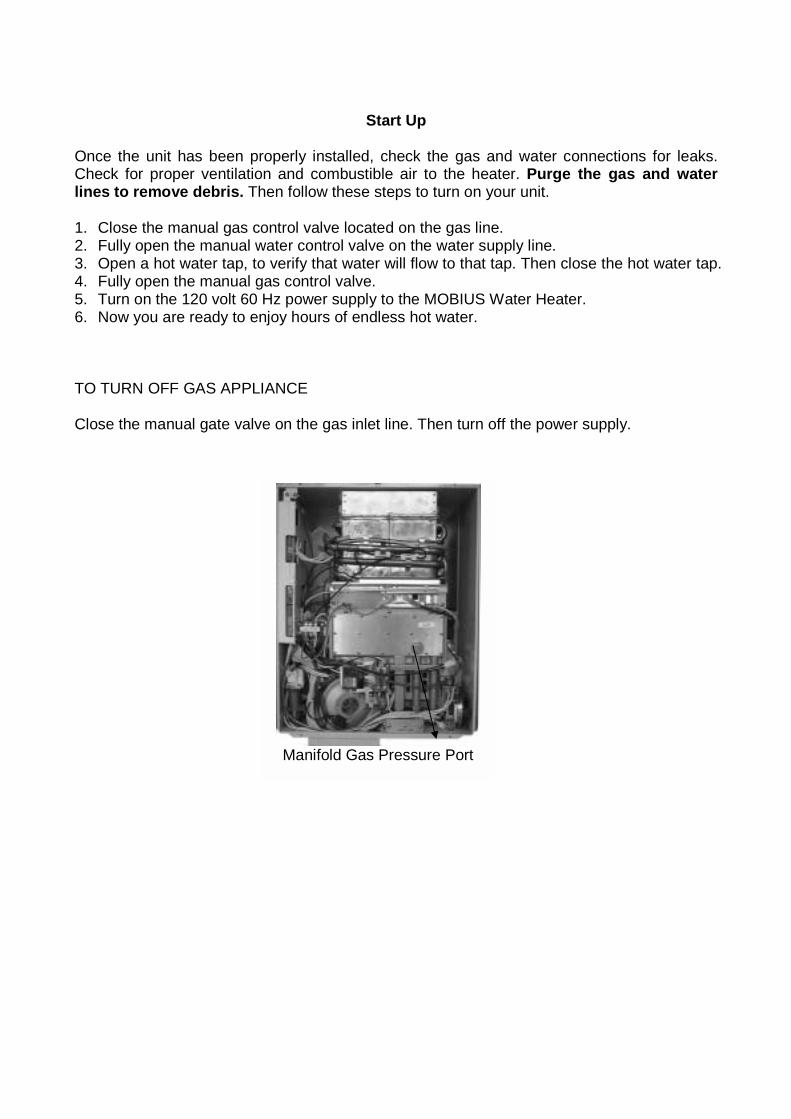
Start Up
Once the unit has been properly installed, check the gas and water connections for leaks. Check for proper ventilation and combustible air to the heater. Purge the gas and water lines to remove debris. Then follow these steps to turn on your unit. 1. Close the manual gas control valve located on the gas line. 2. Fully open the manual water control valve on the water supply line. 3. Open a hot water tap, to verify that water will flow to that tap. Then close the hot water tap. 4. Fully open the manual gas control valve. 5. Turn on the 120 volt 60 Hz power supply to the MOBIUS Water Heater. 6. Now you are ready to enjoy hours of endless hot water. TO TURN OFF GAS APPLIANCE Close the manual gate valve on the gas inlet line. Then turn off the power supply.
Manifold Gas Pressure Port
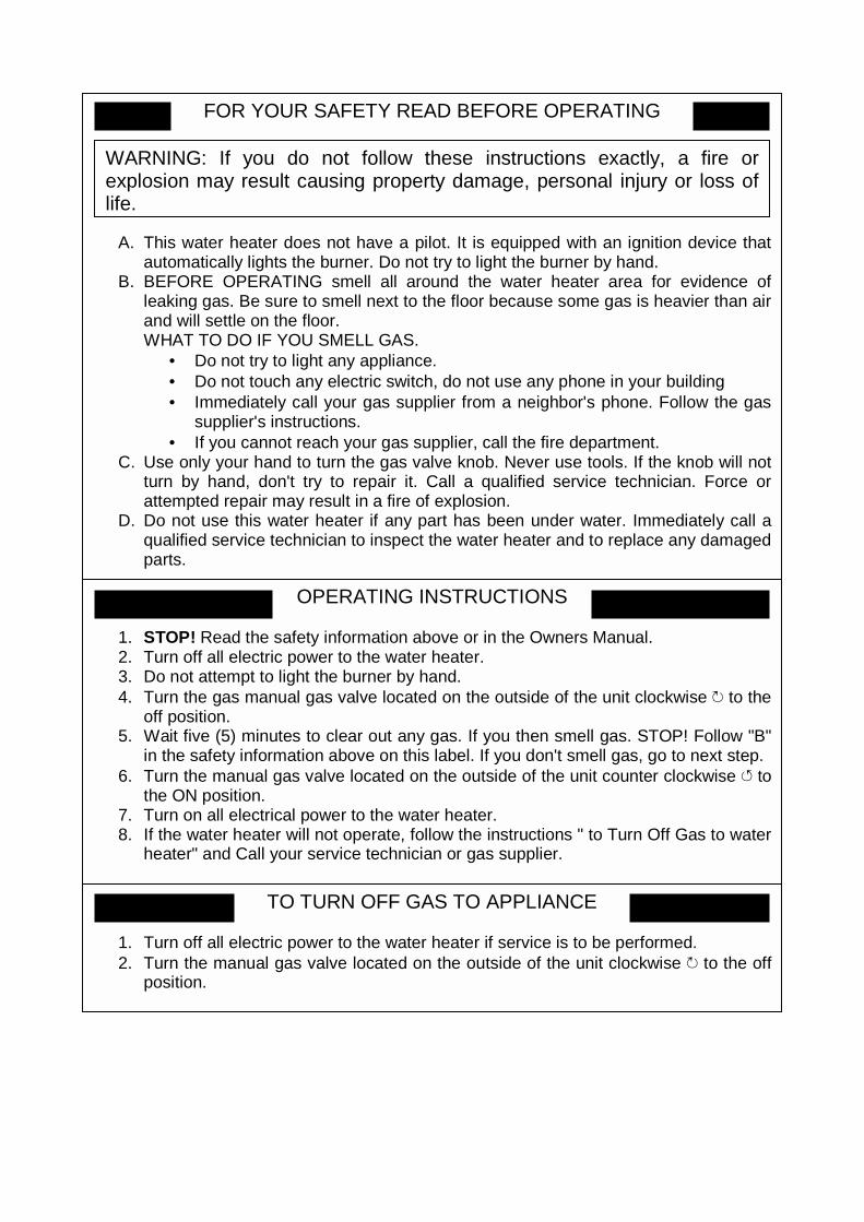
FOR YOUR SAFETY READ BEFORE OPERATING
A. This water heater does not have a pilot. It is equipped with an ignition device that
automatically lights the burner. Do not try to light the burner by hand. B. BEFORE OPERATING smell all around the water heater area for evidence of
leaking gas. Be sure to smell next to the floor because some gas is heavier than air and will settle on the floor. WHAT TO DO IF YOU SMELL GAS.
• Do not try to light any appliance. • Do not touch any electric switch, do not use any phone in your building • Immediately call your gas supplier from a neighbor's phone. Follow the gas
supplier's instructions. • If you cannot reach your gas supplier, call the fire department.
C. Use only your hand to turn the gas valve knob. Never use tools. If the knob will not turn by hand, don't try to repair it. Call a qualified service technician. Force or attempted repair may result in a fire of explosion.
D. Do not use this water heater if any part has been under water. Immediately call a qualified service technician to inspect the water heater and to replace any damaged parts.
WARNING: If you do not follow these instructions exactly, a fire or explosion may result causing property damage, personal injury or loss of life.
OPERATING INSTRUCTIONS
1. STOP! Read the safety information above or in the Owners Manual. 2. Turn off all electric power to the water heater. 3. Do not attempt to light the burner by hand. 4. Turn the gas manual gas valve located on the outside of the unit clockwise ↻ to the
off position. 5. Wait five (5) minutes to clear out any gas. If you then smell gas. STOP! Follow "B"
in the safety information above on this label. If you don't smell gas, go to next step.6. Turn the manual gas valve located on the outside of the unit counter clockwise ↺ to
the ON position. 7. Turn on all electrical power to the water heater. 8. If the water heater will not operate, follow the instructions " to Turn Off Gas to water
heater" and Call your service technician or gas supplier.
TO TURN OFF GAS TO APPLIANCE
1. Turn off all electric power to the water heater if service is to be performed. 2. Turn the manual gas valve located on the outside of the unit clockwise ↻ to the off
position.
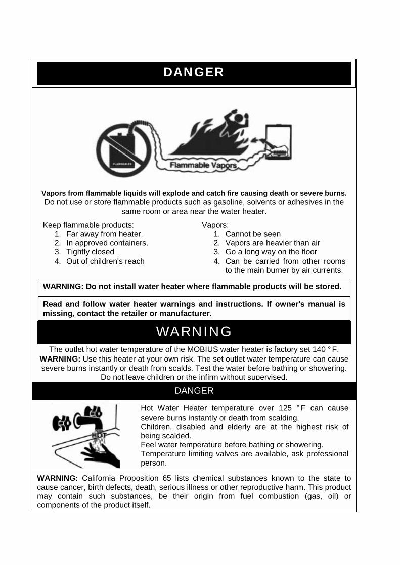
Vapors from flammable liquids will explode and catch fire causing death or severe burns. Do not use or store flammable products such as gasoline, solvents or adhesives in the
same room or area near the water heater.
WARNING: Do not install water heater where flammable products will be stored.
Read and follow water heater warnings and instructions. If owner's manual ismissing, contact the retailer or manufacturer.
WARNING The outlet hot water temperature of the MOBIUS water heater is factory set 140 ° F.
WARNING: Use this heater at your own risk. The set outlet water temperature can cause severe burns instantly or death from scalds. Test the water before bathing or showering.
Do not leave children or the infirm without supervised.
DANGER
Keep flammable products: 1. Far away from heater. 2. In approved containers. 3. Tightly closed 4. Out of children's reach
Vapors: 1. Cannot be seen 2. Vapors are heavier than air 3. Go a long way on the floor 4. Can be carried from other rooms
to the main burner by air currents.
DANGER
Hot Water Heater temperature over 125 ° F can cause severe burns instantly or death from scalding. Children, disabled and elderly are at the highest risk of being scalded. Feel water temperature before bathing or showering. Temperature limiting valves are available, ask professional person.
WARNING: California Proposition 65 lists chemical substances known to the state to cause cancer, birth defects, death, serious illness or other reproductive harm. This product may contain such substances, be their origin from fuel combustion (gas, oil) or components of the product itself.
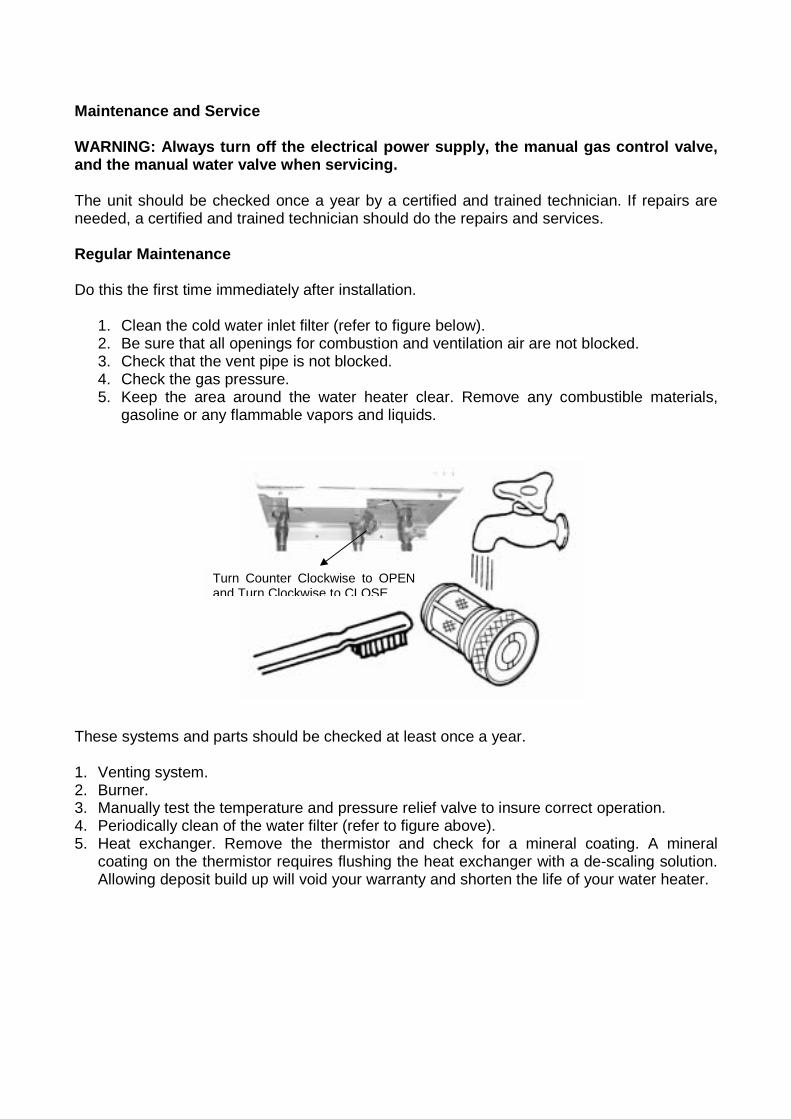
Maintenance and Service WARNING: Always turn off the electrical power supply, the manual gas control valve, and the manual water valve when servicing. The unit should be checked once a year by a certified and trained technician. If repairs are needed, a certified and trained technician should do the repairs and services. Regular Maintenance Do this the first time immediately after installation.
1. Clean the cold water inlet filter (refer to figure below). 2. Be sure that all openings for combustion and ventilation air are not blocked. 3. Check that the vent pipe is not blocked. 4. Check the gas pressure. 5. Keep the area around the water heater clear. Remove any combustible materials,
gasoline or any flammable vapors and liquids. These systems and parts should be checked at least once a year. 1. Venting system. 2. Burner. 3. Manually test the temperature and pressure relief valve to insure correct operation. 4. Periodically clean of the water filter (refer to figure above). 5. Heat exchanger. Remove the thermistor and check for a mineral coating. A mineral
coating on the thermistor requires flushing the heat exchanger with a de-scaling solution. Allowing deposit build up will void your warranty and shorten the life of your water heater.
Turn Counter Clockwise to OPEN and Turn Clockwise to CLOSE.
Cleaning the Heat Exchanger If the heat exchanger must be cleaned, follow this procedure.
1. Shut off all power to the water heater. 2. Use re-circulation method. 3. Wear Gloves when handling de-scaling solution. 4. Always ware EYE PROTECTION. 5. All equipment being de-scaled should be properly vented to prevent gas pressure
build-up during the cleaning operation. 6. Clean out any debris, which has fallen to the coldwater inlet filter.
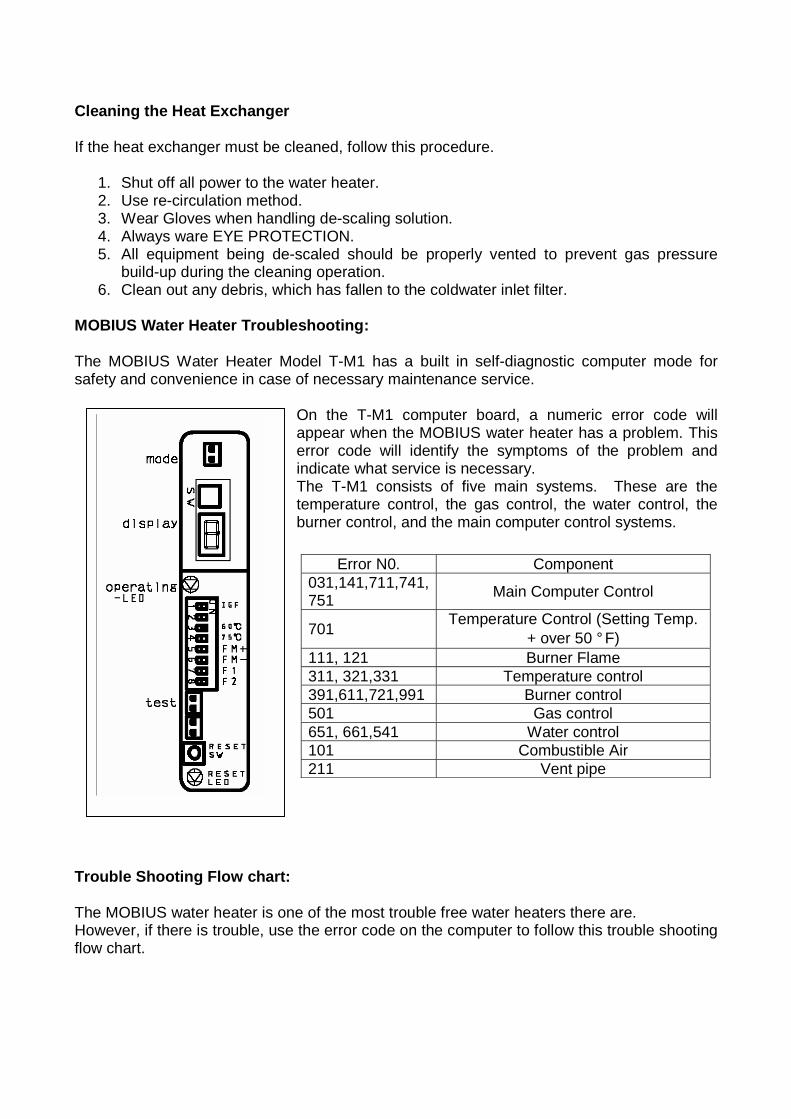
MOBIUS Water Heater Troubleshooting: The MOBIUS Water Heater Model T-M1 has a built in self-diagnostic computer mode for safety and convenience in case of necessary maintenance service.
On the T-M1 computer board, a numeric error code will appear when the MOBIUS water heater has a problem. This error code will identify the symptoms of the problem and indicate what service is necessary. The T-M1 consists of five main systems. These are the temperature control, the gas control, the water control, the burner control, and the main computer control systems.
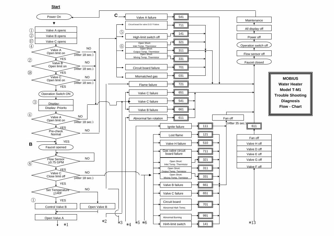
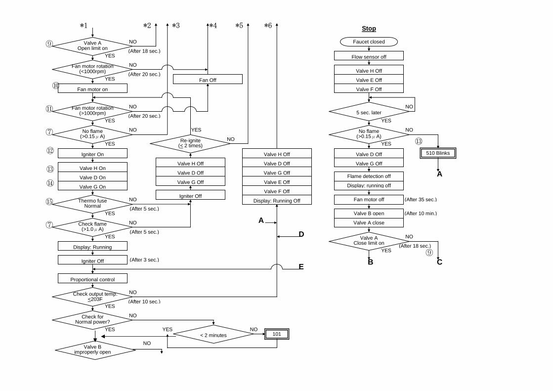
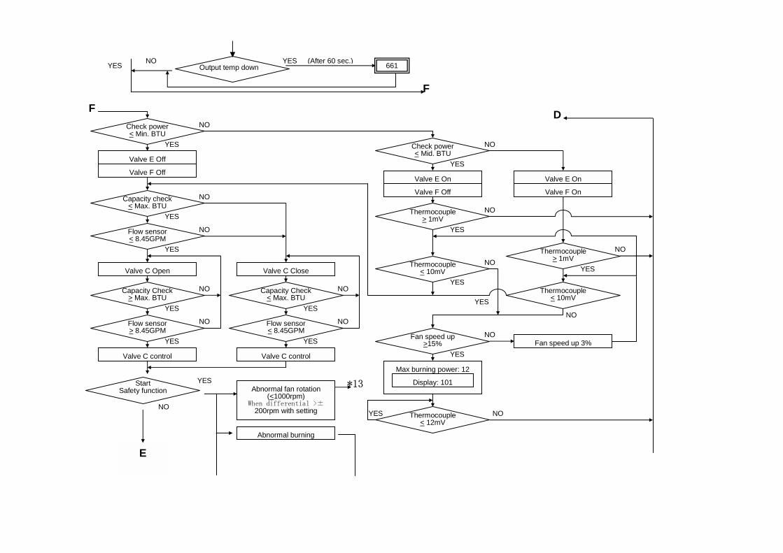
Trouble Shooting Flow chart: The MOBIUS water heater is one of the most trouble free water heaters there are. However, if there is trouble, use the error code on the computer to follow this trouble shooting flow chart.
Error N0. Component 031,141,711,741, 751 Main Computer Control
701 Temperature Control (Setting Temp. + over 50 ° F)
111, 121 Burner Flame 311, 321,331 Temperature control 391,611,721,991 Burner control 501 Gas control 651, 661,541 Water control 101 Combustible Air 211 Vent pipe
①
541
711
141
321
311
331
701
031
721
651
541
661
611
111
121
510
711
321
311
331
661
651
701
991
141
Circuit board for valve D.E.F Failure
Valve B failure
Valve C failure
Circuit board
Abnormal High Temp.
High-limit switch
YES
YES
YES
YES
YES
YES
YES
Valve AOpen limit on
Valve C
Open limit on
Valve AOpen limit on
Pre-checkNormal
Flow Sensor>0.75 GPM
Valve CClose limit off
Set Temperature<140F
Power On
Operation Switch ON
Faucet opened
NO
(After 18 sec.)
NO
(After 18 sec.)
NO
(After 18 sec.)
NO
(After 18 sec.)
NO
NO
NO
(After 18 sec.)
NO
Valve BOpen limit on
C
⑥
⑤
*1
*2 *3 Abnormal Burning
*5 *6
YES
②
②
①
⑰ ④
⑧
③
④
⑱
(After 35 sec.)
Valve A opens
Valve B opens
Valve C opens
Display: Display: Priority
Control Valve B Open Valve B
Open Valve A
611
*13*4
Valve A failure
High-limit switch off
Open Short: Inlet Temp. Thermistor
Open Short: Output Temp. Thermistor
Open Short: Mixing Temp. Thermistor
Circuit board failure
Mismatched gas
Flame failure
Valve C failure
Abnormal fan rotation
Ignite failure
Lost flame
Valve C failure
Valve B failure
Valve H failure
Gas valve circuit board failure
Open Short: Inlet Temp. Thermistor
Open Short: Output Temp. Termistor
Open Short: Mixing Temp. Termistor
Fan off
Faucet closed
Flow sensor off
Operation switch off
Power off
All display off
Maintenance
Start
Fan off
Valve H off
Valve D off
Valve G off
Valve E off
Valve F off
B
MOBIUS Water Heater Model T-M1
Trouble Shooting Diagnosis
Flow - Chart
*4
YES
YES
⑩
⑨
*1
YES
YES
⑫
⑪
YES
YES
⑮
YES
YES
NO
NO
NO
NO
NO
NO
NO
NO
NO
*2
(After 18 sec.)
*3
YES
NO
*5
(After 20 sec.)
(After 20 sec.)
(After 5 sec.)
(After 5 sec.)
*6
A
(After 3 sec.)
(After 10 sec.)
101NOYES
Valve AOpen limit on
Fan motor rotation(<1000rpm)
Fan motor on
Fan motor rotation(>1000rpm)
No flame(>0.15μA)
Igniter On
Valve H On
Valve D On
Valve G On
Thermo fuseNormal
Check flame(>1.0μA)
Display: Running
Igniter Off
Proportional control
Check output temp. <203F
Check forNormal power?
Valve B improperly open
< 2 minutes
Fan Off
Re-ignite(< 2 times)
Valve H Off
Valve D Off
Valve G Off
Igniter Off
Valve H Off
Valve D Off
Valve G Off
Valve E Off
Valve F Off
Display: Running Off
⑦
⑬
⑭
⑦D
E
YES
YES
5 sec. later
Valve AClose limit on
Faucet closed
NO
NO
(After 35 sec.)
NO
(After 18 sec.)
Valve H Off
Valve E Off
Valve F Off
Flame detection off
Display: running off
Stop
Flow sensor off
No flame(>0.15μA)
Valve D Off
Valve G Off
Fan motor off
Valve B open
Valve A close
B
510 Blinks
⑬
A
(After 10 min.)
C⑨YES
YES 661 NO YES
YES
NO
YES
NO
YES
NO
YES
NO
YES
NO
YES
NO
YES
NO
YES
NO
YES
NO
YES
NO
YES NO
YES
NO
YES
NO
YES
NO
YES
NO
Output temp down(After 60 sec.)
F
F DCheck power < Min. BTU
Valve E Off
Valve F Off
Capacity check < Max. BTU
Flow sensor < 8.45GPM
Valve C Open
StartSafety function
Capacity Check > Max. BTU
Flow sensor > 8.45GPM
Valve C control
Valve C Close
Capacity Check< Max. BTU
Flow sensor< 8.45GPM
Valve C control
Check power < Mid. BTU
Valve E On
Valve F Off
Valve E On
Valve F On
Thermocouple > 1mV
Thermocouple < 10mV
Thermocouple> 1mV
Thermocouple< 10mV
Fan speed up >15%
Display: 101
Max burning power: 12
Thermocouple < 12mV
Fan speed up 3%
*13Abnormal fan rotation(<1000rpm)
When differential >±200rpm with setting
Abnormal burning
E
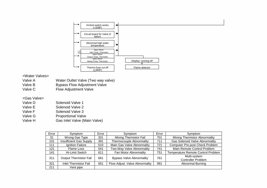
<Water Valves> Valve A Water Outlet Valve (Two way valve) Valve B Bypass Flow Adjustment Valve Valve C Flow Adjustment Valve <Gas Valve> Valve D Solenoid Valve 1 Valve E Solenoid Valve 2 Valve F Solenoid Valve 3 Valve G Proportional Valve Valve H Gas Inlet Valve (Main Valve)
Error Symptom Error Symptom Error Symptom 31 Wrong Gas Type 331 Mixing Thermistor Fail 701 Mixing Thermistor Abnormality 101 Insufficient Gas Supply 391 Thermocouple Abnormality 711 Gas Solenoid Valve Abnormality 111 Ignition Failure 510 Main Gas Valve Abnormality 721 Computer Pre-post Check Problem 121 Flame Loss 541 Two-Way Valve Abnormality 741 Main Remote Control Problem 141 Hi-Limit Switch 611 Fan Motor Abnormality 751 Temperature Remote Control Problem
311 Output Thermistor Fail 661 Bypass Valve Abnormality 761 Multi-system Controller Problem
321 Inlet Thermistor Fail 651 Flow Adjust. Valve Abnormality 991 Abnormal Burning 211 Vent pipe
Hi-limit switch works (>208F)
Circuit board for Valve D failure
Abnormal high watertemperature
⑥Open Short:
Output Temp. Thermister Open Short:
Mixing Temp. Thermister
Open Short: Inlet Temp. Thermister
Thermo fuse cut off(>360F)
Flame detector
Display: running off
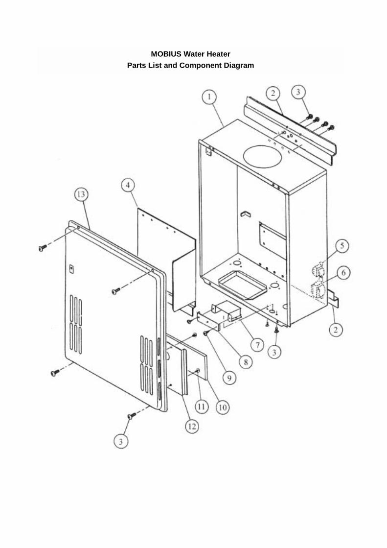
MOBIUS Water Heater Parts List and Component Diagram
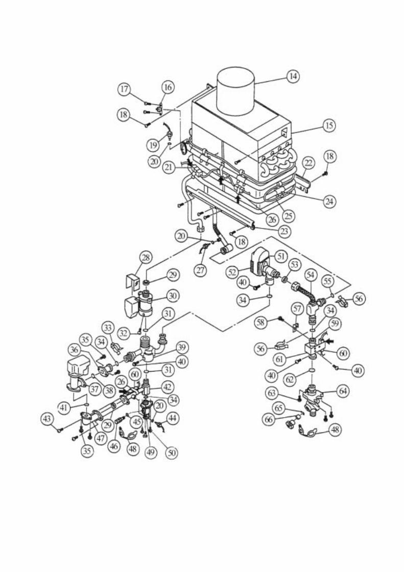
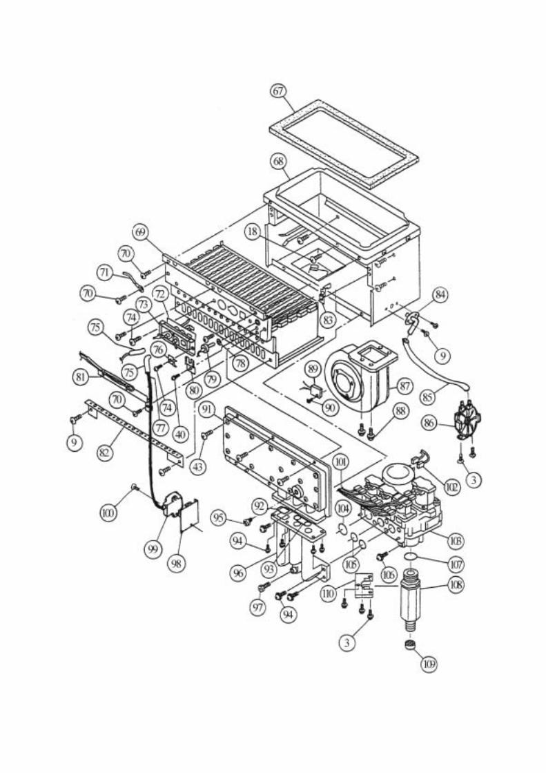
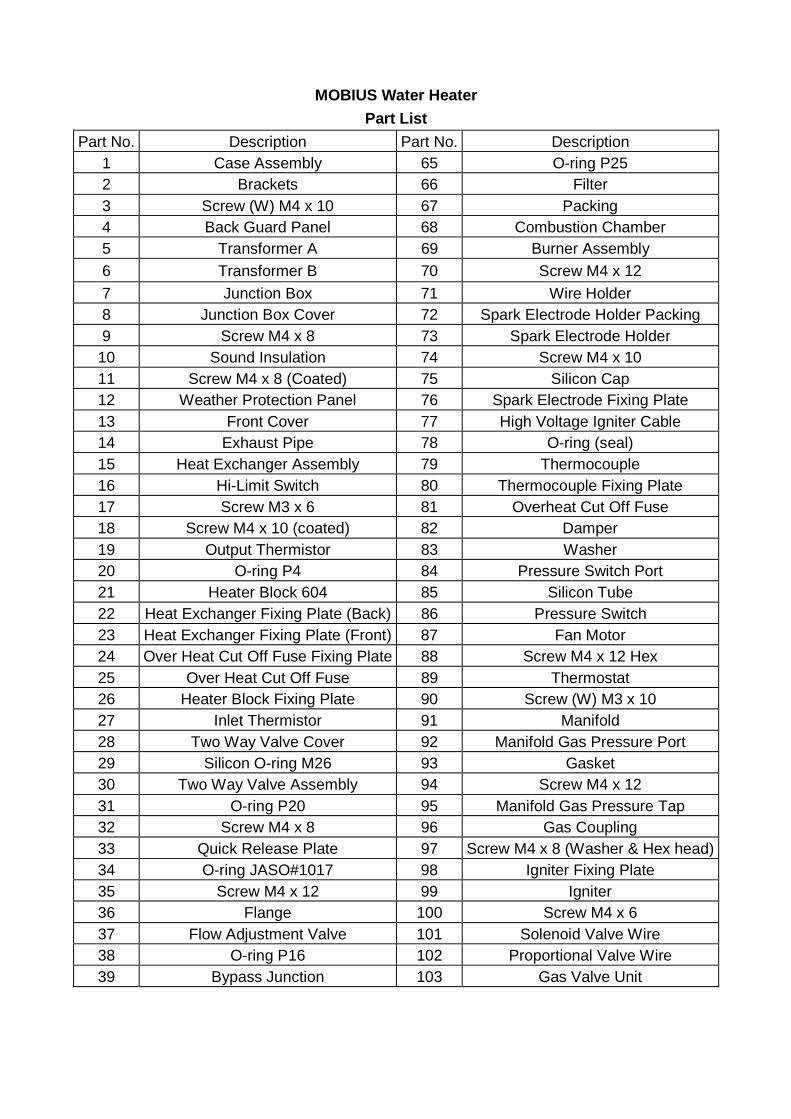
MOBIUS Water Heater Part List
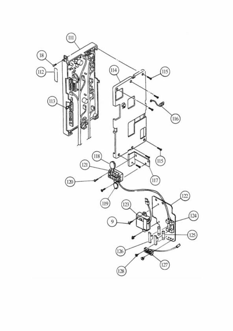
Part No. Description Part No. Description 1 Case Assembly 65 O-ring P25 2 Brackets 66 Filter 3 Screw (W) M4 x 10 67 Packing 4 Back Guard Panel 68 Combustion Chamber 5 Transformer A 69 Burner Assembly 6 Transformer B 70 Screw M4 x 12 7 Junction Box 71 Wire Holder 8 Junction Box Cover 72 Spark Electrode Holder Packing 9 Screw M4 x 8 73 Spark Electrode Holder 10 Sound Insulation 74 Screw M4 x 10 11 Screw M4 x 8 (Coated) 75 Silicon Cap 12 Weather Protection Panel 76 Spark Electrode Fixing Plate 13 Front Cover 77 High Voltage Igniter Cable 14 Exhaust Pipe 78 O-ring (seal) 15 Heat Exchanger Assembly 79 Thermocouple 16 Hi-Limit Switch 80 Thermocouple Fixing Plate 17 Screw M3 x 6 81 Overheat Cut Off Fuse 18 Screw M4 x 10 (coated) 82 Damper 19 Output Thermistor 83 Washer 20 O-ring P4 84 Pressure Switch Port 21 Heater Block 604 85 Silicon Tube 22 Heat Exchanger Fixing Plate (Back) 86 Pressure Switch 23 Heat Exchanger Fixing Plate (Front) 87 Fan Motor 24 Over Heat Cut Off Fuse Fixing Plate 88 Screw M4 x 12 Hex 25 Over Heat Cut Off Fuse 89 Thermostat 26 Heater Block Fixing Plate 90 Screw (W) M3 x 10 27 Inlet Thermistor 91 Manifold 28 Two Way Valve Cover 92 Manifold Gas Pressure Port 29 Silicon O-ring M26 93 Gasket 30 Two Way Valve Assembly 94 Screw M4 x 12 31 O-ring P20 95 Manifold Gas Pressure Tap 32 Screw M4 x 8 96 Gas Coupling 33 Quick Release Plate 97 Screw M4 x 8 (Washer & Hex head)34 O-ring JASO#1017 98 Igniter Fixing Plate 35 Screw M4 x 12 99 Igniter 36 Flange 100 Screw M4 x 6 37 Flow Adjustment Valve 101 Solenoid Valve Wire 38 O-ring P16 102 Proportional Valve Wire 39 Bypass Junction 103 Gas Valve Unit
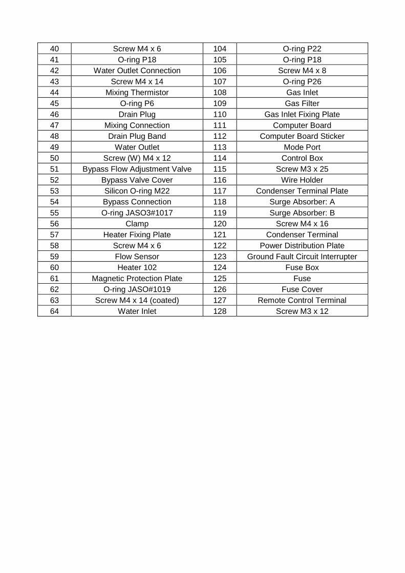
40 Screw M4 x 6 104 O-ring P22 41 O-ring P18 105 O-ring P18 42 Water Outlet Connection 106 Screw M4 x 8 43 Screw M4 x 14 107 O-ring P26 44 Mixing Thermistor 108 Gas Inlet 45 O-ring P6 109 Gas Filter 46 Drain Plug 110 Gas Inlet Fixing Plate 47 Mixing Connection 111 Computer Board 48 Drain Plug Band 112 Computer Board Sticker 49 Water Outlet 113 Mode Port 50 Screw (W) M4 x 12 114 Control Box 51 Bypass Flow Adjustment Valve 115 Screw M3 x 25 52 Bypass Valve Cover 116 Wire Holder 53 Silicon O-ring M22 117 Condenser Terminal Plate 54 Bypass Connection 118 Surge Absorber: A 55 O-ring JASO3#1017 119 Surge Absorber: B 56 Clamp 120 Screw M4 x 16 57 Heater Fixing Plate 121 Condenser Terminal 58 Screw M4 x 6 122 Power Distribution Plate 59 Flow Sensor 123 Ground Fault Circuit Interrupter 60 Heater 102 124 Fuse Box 61 Magnetic Protection Plate 125 Fuse 62 O-ring JASO#1019 126 Fuse Cover 63 Screw M4 x 14 (coated) 127 Remote Control Terminal 64 Water Inlet 128 Screw M3 x 12
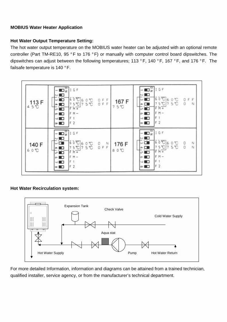
MOBIUS Water Heater Application
Hot Water Output Temperature Setting: The hot water output temperature on the MOBIUS water heater can be adjusted with an optional remote controller (Part TM-RE10, 95 ° F to 176 ° F) or manually with computer control board dipswitches. The dipswitches can adjust between the following temperatures; 113 ° F, 140 ° F, 167 ° F, and 176 °F. The failsafe temperature is 140 °F.
Hot Water Recirculation system:
For more detailed Information, information and diagrams can be attained from a trained technician, qualified installer, service agency, or from the manufacturer’s technical department.
Expansion Tank
Cold Water Supply
Check Valve
Pump Hot Water Return
Aqua stat
Hot Water Supply
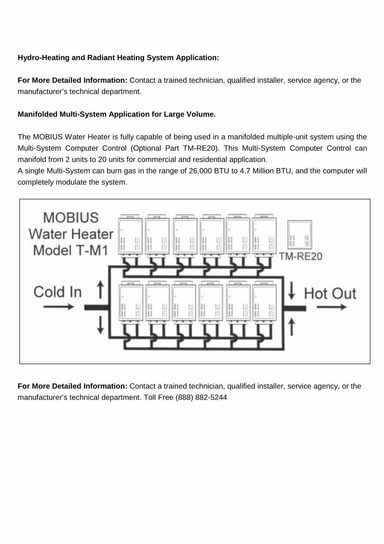
Hydro-Heating and Radiant Heating System Application: For More Detailed Information: Contact a trained technician, qualified installer, service agency, or the manufacturer’s technical department. Manifolded Multi-System Application for Large Volume. The MOBIUS Water Heater is fully capable of being used in a manifolded multiple-unit system using the Multi-System Computer Control (Optional Part TM-RE20). This Multi-System Computer Control can manifold from 2 units to 20 units for commercial and residential application. A single Multi-System can burn gas in the range of 26,000 BTU to 4.7 Million BTU, and the computer will completely modulate the system.
For More Detailed Information: Contact a trained technician, qualified installer, service agency, or the manufacturer’s technical department. Toll Free (888) 882-5244
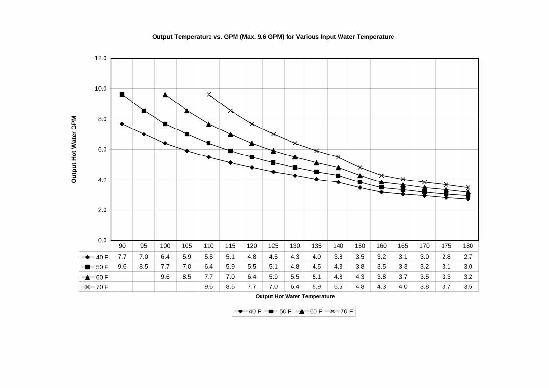
Output Temperature vs. GPM (Max. 9.6 GPM) for Various Input Water Temperature
0.0
2.0
4.0
6.0
8.0
10.0
12.0
Output Hot Water Temperature
Out
put H
ot W
ater
GPM
40 F 50 F 60 F 70 F
40 F 7.7 7.0 6.4 5.9 5.5 5.1 4.8 4.5 4.3 4.0 3.8 3.5 3.2 3.1 3.0 2.8 2.7
50 F 9.6 8.5 7.7 7.0 6.4 5.9 5.5 5.1 4.8 4.5 4.3 3.8 3.5 3.3 3.2 3.1 3.0
60 F 9.6 8.5 7.7 7.0 6.4 5.9 5.5 5.1 4.8 4.3 3.8 3.7 3.5 3.3 3.2
70 F 9.6 8.5 7.7 7.0 6.4 5.9 5.5 4.8 4.3 4.0 3.8 3.7 3.5
90 95 100 105 110 115 120 125 130 135 140 150 160 165 170 175 180