MIT OpenCourseWare ://ocw.mit.edu/courses/mechanical-engineering/2-0… · ·...
56
MIT OpenCourseWare http://ocw.mit.edu 2.00AJ / 16.00AJ Exploring Sea, Space, & Earth: Fundamentals of Engineering Design Spring 2009 For information about citing these materials or our Terms of Use, visit: http://ocw.mit.edu/terms.
Transcript of MIT OpenCourseWare ://ocw.mit.edu/courses/mechanical-engineering/2-0… · ·...

MIT OpenCourseWare http://ocw.mit.edu
2.00AJ / 16.00AJ Exploring Sea, Space, & Earth: Fundamentals of Engineering Design Spring 2009
For information about citing these materials or our Terms of Use, visit: http://ocw.mit.edu/terms.
FUNdaMENTALs for DesignAnalysis:
Fluid Effects & Forces
Prof. A. H. Techet2.00a/16.00a Lecture 4
Spring 2009

Water & AirCourtesy of NASA.
Courtesy of the U.S. Navy.
Image by Leonardo da Vinci.
• Hydrodynamics v. Aerodynamics – Water is almost 1000 times denser than air!
• Air • Water – Density – Density
31.2 /kg m! =
31025 / (seawater)kg m! =
31000 / (freshwater)kg m! =
– 5 2
1.82 10 /N s mµ != " #
Dynamic Viscosity – Dynamic Viscosity
– Kinematic Viscosity – Kinematic Viscosity
5 2/ 1.51 10 /m s! µ " #
= = $6 2
1 10 /m s!"
= #
3 21.0 10 /N s mµ !
= " #
Fluid Properties @20ºC

Hydrostatic Pressure

Pressure under water
• Pressure is a Force per Area (P = F/A)
Pressure is a Normal Stress
?? Pressure is isotropic.
?? How does it act on these 2D shapes?

Pressure increases with depth
• Hydrostatic Pressure gdz
dp!"=
• Pressure on a vertical wall:
Absolute Pressure
( )hzgpp a !!=! "
Gauge Pressure
)( zhgpg != "
+z
The NET pressure force acts at the CENTER of PRESSURE
FOR MORE DETAILS WITH THE DERIVATION OF THE HYDROSTATIC EQUATION,SEE THE READING ON PRESSURE POSTED ON THE CLASS WEBPAGE

Pressure on a sphere at depth?
ˆ
S
F p n dS= !""
Pressure acts normal to the surface. By convention pressure is positive in compression. The total force is the integration of the ambient pressure over the surface area of the sphere.

Archimedes’ Principle
x
z
DL
M
W
Weight of the displaced volume of fluid is equal to the hydrostatic pressure acting on the bottom of the vessel integrated over the area.
Fg
FB
Pressure, p
Fz = p*A = (ρ g D) * (L W) = ρ g* (L D W) = ρ g * Volume BUOYANCY FORCE -->
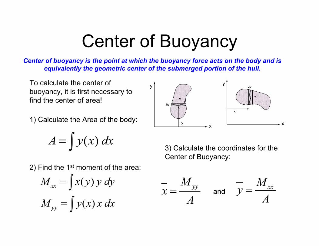
Center of Buoyancy Center of buoyancy is the point at which the buoyancy force acts on the body and is
equivalently the geometric center of the submerged portion of the hull.
To calculate the center of buoyancy, it is first necessary to find the center of area!
1) Calculate the Area of the body:
( )A y x dx= ! 3) Calculate the coordinates for the Center of Buoyancy:
2) Find the 1st moment of the area:
( )yyM y x x dx= !
( )xxM x y y dy= ! yyMx
A=
xxMy
A=and

Stability? A statically stable vessel with a positive righting arm.
“self-righting”
Statically unstable vessel with a negative righting arm.
Fluids in Motion…

Fluids Follow Basic Laws
• Conservation of Mass • Conservation of Momentum
• Conservation of Energy
Flows can be described simply
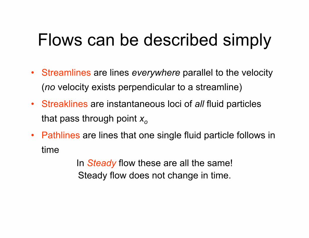
• Streamlines are lines everywhere parallel to the velocity (no velocity exists perpendicular to a streamline)
• Streaklines are instantaneous loci of all fluid particles that pass through point xo
• Pathlines are lines that one single fluid particle follows in time
In Steady flow these are all the same!Steady flow does not change in time.

Conservation of MassWhat goes in must come out!
Area A
Area a
Control Volume: nozzle
U V
Mass:
m != "density * volume
Volume: area * length
A L! = "
Length: velocity * time
L U t= !"
To conserve Mass:
!m = "AU # $t
!AU " #t
min
!"# $#= !aV " #t
mout
!"# $#in outm m=

Conservation of Momentum
Newton’s second law states that the time rate of change ofmomentum of a system of particles is equal to the sum of
external forces acting on that body.dA
{ }dm
dt! =
iF V
P P + dP
Forces: • Gravity (hydrostatic) • Pressure !!!
xP! =F dA P"( )
dvdP dA m
dt+ =
• Shear (viscous/friction) • External Body
x
dvdPdA m
dt! = " =F
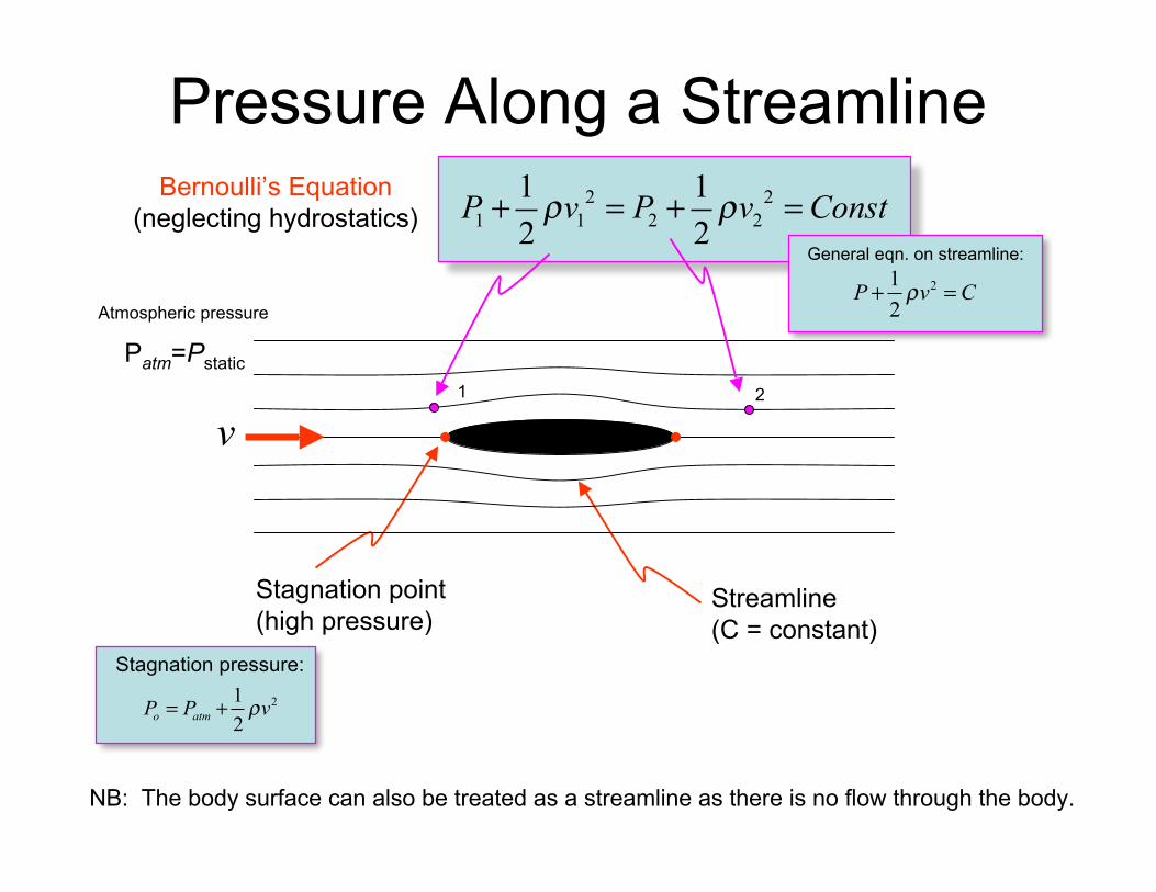
Pressure Along a Streamline
Patm=Pstatic
v
Stagnation point Streamline
Atmospheric pressure
2 2
1 1 2 2
1 1
2 2P v P v Const! !+ = + =
Bernoulli’s Equation (neglecting hydrostatics)
1 2
General eqn. on streamline:
21
2P v C!+ =
(high pressure) (C = constant)
21
2o atmP P v!= +
Stagnation pressure:
NB: The body surface can also be treated as a streamline as there is no flow through the body.
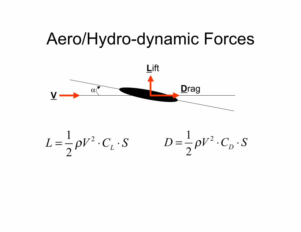
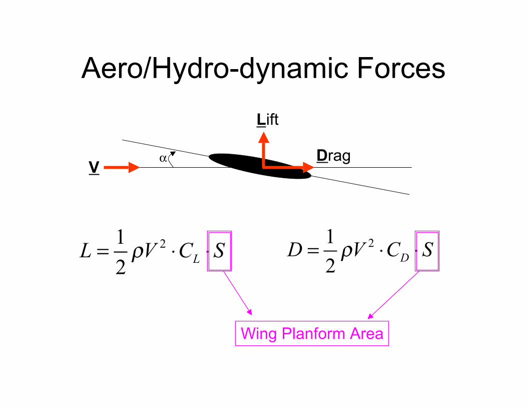
Aero/Hydro-dynamic Forces
21
2L
L V C S!= " "
αV
Lift
Drag
21
2D
D V C S!= " "

Aero/Hydro-dynamic Forces
21
2L
L V C S!= " "
αV
Lift
Drag
21
2D
D V C S!= " "
Dynamic Pressure (like in Bernoulli’s equation!!)
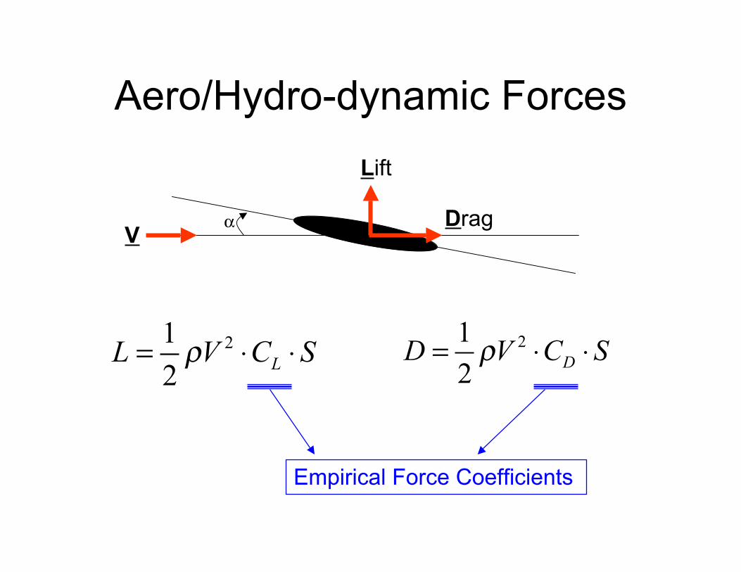
Aero/Hydro-dynamic Forces
21
2L
L V C S!= " "
αV
Lift
Drag
21
2D
D V C S!= " "
Empirical Force Coefficients
Aero/Hydro-dynamic Forces
21
2L
L V C S!= " "
αV
Lift
Drag
21
2D
D V C S!= " "
Wing Planform Area
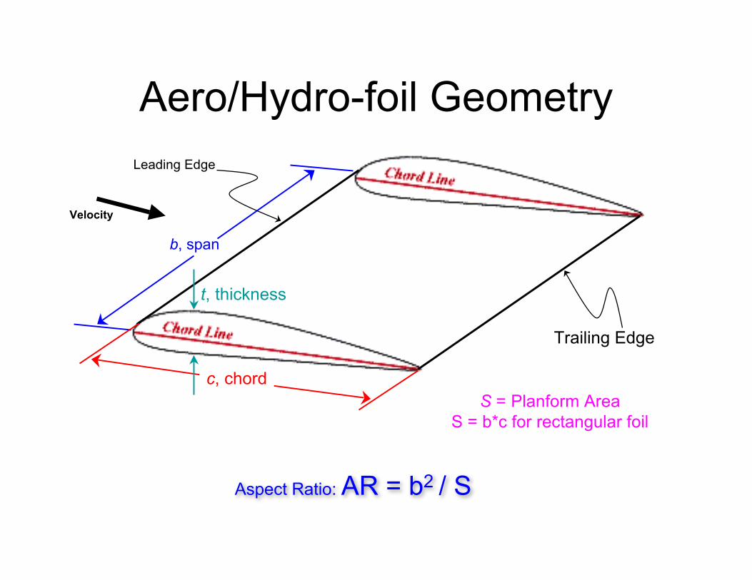
Aero/Hydro-foil Geometry
b, span
c, chord
t, thickness
S = Planform Area
Leading Edge
Trailing Edge
Velocity
S = b*c for rectangular foil
Aspect Ratio: AR = b2 / S

Lift on a hydrofoil
Courtesy of Spyros A. Kinnas. Used with permission.

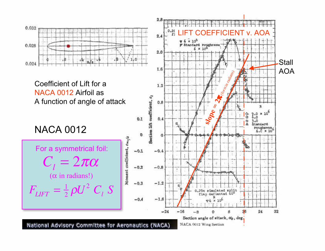
Coefficient of Lift for a NACA 0012 Airfoil as A function of angle of attack
NACA 0012
First two numbers indicate camber Double zeros indicate symmetric foil
LIFT COEFFICIENT v. AOA

Coefficient of Lift for a NACA 0012 Airfoil as A function of angle of attack
NACA 0012
Last two numbers indicate thickness of foil as % of total chord length
LIFT COEFFICIENT v. AOA
slope
= 2π (
forα
inra
dian
s)
Stall AOA
Coefficient of Lift for a NACA 0012 Airfoil as A function of angle of attack
NACA 0012
LIFT COEFFICIENT v. AOA
For a symmetrical foil:
Cl= 2!"
(α in radians!)
FLIFT
=1
2!U 2
ClS
Maneuvering with a Rudder
Images removed due to copyright restrictions.Please see: Fig. 14-1 and 14-2 in Gillmer, Thomas Charles, and Bruce Johnson.Introduction to Naval Architecture.Annapolis, MD: U.S. Naval Institute Press, 1982.

Images removed due to copyright restrictions.Please see Fig. 14-5, 14-6, and 14-9 in Gillmer, Thomas Charles, and Bruce Johnson.Introduction to Naval Architecture. Annapolis, MD: U.S. Naval Institute Press, 1982.

Turning Moment on a Vehicle
Vehicle Forward speed M
T, thrust Moment Arm, r
M = r x T
Single Motor Turn
Sum of the Moments (Torques) about the CG equals the time rate of change of angular momentum
α
Vehicle Forward
speed
LIFT, L
Moment Arm, r
M
M = r x L
Lift on the Rudder:
L = 1/2 ρV2 (2 π α) A
A = area of rudder α in radians
Coefficient of Lift:
CL= 2 π α
Turning a Vehicle with a Rudder
Σ MCG = Ιθ ..
Ι = moment of Inertia of the vehicle about CG*
*can calculate in Solidworks!

Viscous Drag
laminar turbulent
Skin Friction Drag: Cf
Form Drag: CD due to pressure (turbulence, separation)
Streamlined bodies reduce separation, thus reduce form drag.Bluff bodies have strong separation thus high form drag.

Friction Drag The transfer of momentum between the fluid particles slows the flow down causing drag on the plate. This drag is referred to as friction drag.
[ ]
[ ]
2
221
2
f
w
MLT
MLT
FC
U A!
"
"=
Friction Drag Coefficient:
units
(non-dimensional coefficient)
A = Wetted Area w
THIS IS A SHEAR FORCE THAT COMES FROM SHEAR STRESS AT THE WALL!
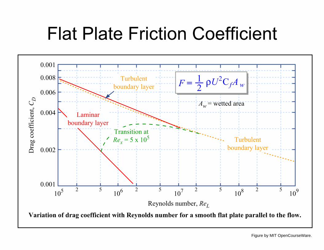
Flat Plate Friction Coefficient
Turbulentboundary layer
Turbulentboundary layer
Transition atRex = 5 x 10⁵
Laminarboundary layer
Aw = wetted area
105 106 107 108 1092 5 2 5 2 5 2 50.001
0.002
0.004
0.006
0.008
0.001
Dra
g co
effic
ient
, CD
Reynolds number, ReL
Variation of drag coefficient with Reynolds number for a smooth flat plate parallel to the flow.
F = 12 ρU2C fA w
Figure by MIT OpenCourseWare.
Viscous flow around bluff bodies (like cylinders) tends to
separate and form drag dominates over friction drag.

Drag on Bodies
DRAG ACTSINLINE WITHVELOCITY
Image removed due to copyright restrictions.Please see http://www.onera.fr/photos-en/tunnel/images/220006.jpg
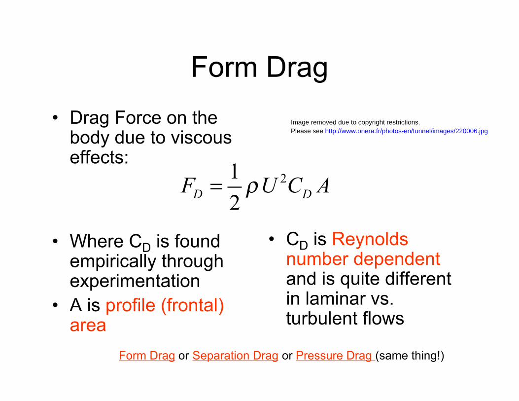
Form Drag
• Drag Force on thebody due to viscouseffects:
Image removed due to copyright restrictions.Please see http://www.onera.fr/photos-en/tunnel/images/220006.jpg
21
2D DF U C A!=
• Where CD is found empirically throughexperimentation
• A is profile (frontal) area
• CD is Reynoldsnumber dependentand is quite differentin laminar vs. turbulent flows
Form Drag or Separation Drag or Pressure Drag (same thing!)

Flow Separating from a Cylinder
Low pressure
High pressureStagnation pressure
Separation point
Y
Y
d
'Negative' velocities(separated flow)
Wake
Figure by MIT OpenCourseWare.

Classical Vortex Shedding
Image removed due to copyright restrictions. Please see http://en.wikipedia.org/wiki/File:Viv2.jpg
Alternately shed opposite signed vortices

Vortex shedding results from a wakeinstability
Images removed due to copyright restrictions.Please see Fig. 25-32 in Homann, Fritz. "Einfluß großer Zähigkeit bei Strömung um Zylinder."Forschung auf dem Gebiete des Ingenieurwesens 7 (January/February 1936): 1-10.
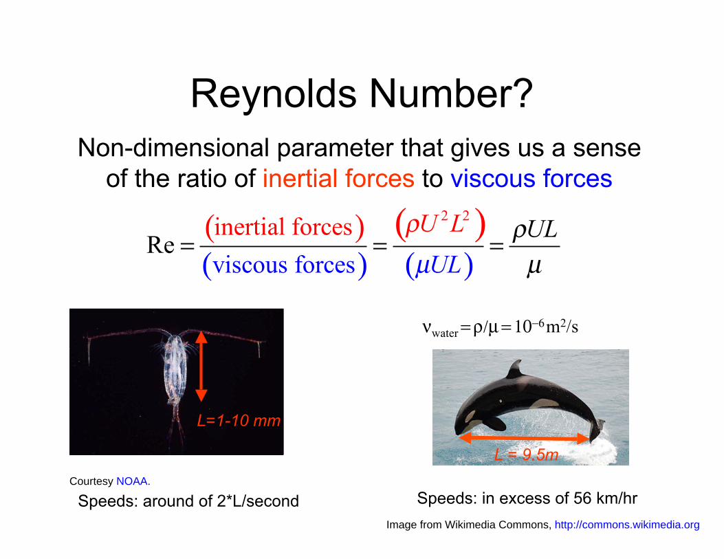
Reynolds Number?Non-dimensional parameter that gives us a sense
of the ratio of inertial forces to viscous forces
( ) ( )) ( )
! 2 2
inertial forces U L !UL= =
viscous forces µUL µ(Re =
νwater = ρ/µ = 10−6 m2/s
L = 9.5m
L=1-10 mm
Courtesy NOAA.
Speeds: around of 2*L/second Speeds: in excess of 56 km/hr Image from Wikimedia Commons, http://commons.wikimedia.org

Reynolds NumberDependence
Rd < 5
5-15 < Rd < 40
40 < Rd < 150
150 < Rd < 300Transition to turbulence
300 < Rd < 3*105
3*105 < Rd < 3.5*106
3.5*106 < Rd
From Blevins
Regime of Unseparated Flow
Regimes of fluid flow across smooth circular cylinders (Lienhard, 1966).
A Fixed Pair of Foppl Vortices in Wake
Two Regimes in which Vortex Street is Laminar
Transition Range to Turbulence in Vortex
Vortex Street is Fully Turbulent
Re-establishment of Turbulent Vortex Street
Laminar Boundary Layer has Undergone Turbulent Transition and Wake is Narrower and Disorganized
Figure by MIT OpenCourseWare.
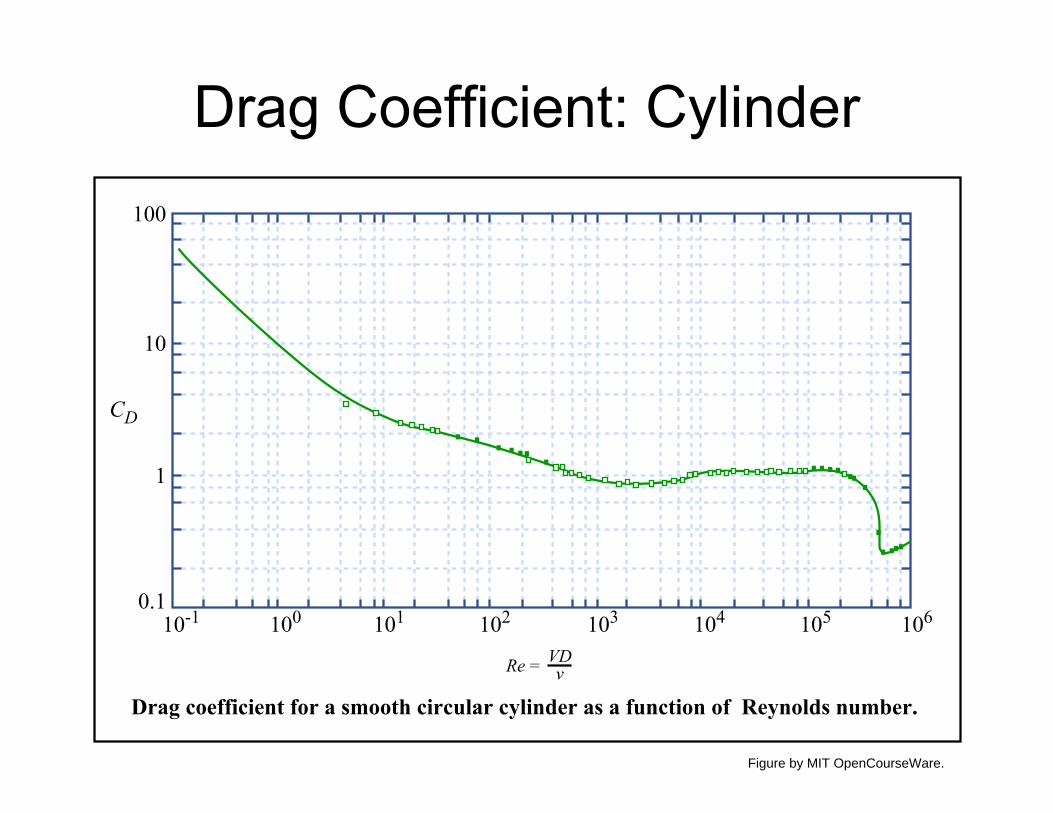
100
10
1
0.1 10-1 100 101 102 103 104 105 106
CD
VDRe = v�
Drag coefficient for a smooth circular cylinder as a function of Reynolds number.
Drag Coefficient: Cylinder
Figure by MIT OpenCourseWare.
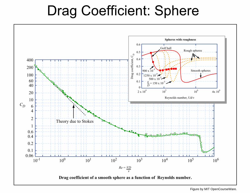
Drag Coefficient: Sphere
0.060.10.20.40.6
1
2
46
1020
4060
100
200
400
10-1 100 101 102 103 104 105 106
CD
Re = VDv
Drag coefficient of a smooth sphere as a function of Reynolds number.
Theory due to Stokes
Rough spheresGolf ball
Smooth spheres
4x 1062 x 104 106105
1250 x 10-5900 x 10-5
500 x 10-5
= 150 x 10-5εD
0
0.1
0.2
0.3
0.4
0.5
0.6
Dra
g co
effic
ient
, CD
Reynolds number, Ud/v
Spheres with roughness
Figure by MIT OpenCourseWare.

Trade-offbetween
Friction andPressure drag
c = Body length inline with flow
t = Body thickness
Images removed due to copyright restrictions.Please see Fig. 7.12 and 7.15 in White, Frank M. Fluid Mechanics. Boston, MA: McGraw-Hill, 2007.

2D Drag Coefficients For 2D shapes: use CD Use a “strip theory” type approach to determine to calculate force per total drag, assuming that the flow is uniform unit length. along the span of the body.
Images removed due to copyright restrictions.Please see Table 7.2 in White, Frank M. Fluid Mechanics. Boston, MA: McGraw-Hill, 2007.

Trade-offbetween
Friction andPressure drag
c = Body length inline with flow
t = Body thickness
Images removed due to copyright restrictions.Please see Table 7.2 in White, Frank M. Fluid Mechanics. Boston, MA: McGraw-Hill, 2007.

3D Drag Coefficients
Images removed due to copyright restrictions.Please see Table 7.3 in White, Frank M. Fluid Mechanics. Boston, MA: McGraw-Hill, 2007.

More 3D Shapes
Images removed due to copyright restrictions.Please see Table 7.3 in White, Frank M. Fluid Mechanics. Boston, MA: McGraw-Hill, 2007.

Calculating Drag on a Simple Structure
Example: Spherical vehicle with motors
Vehicle Forward
speed Drag
Dragtotal = Dragsphere+2*Dragmotors
Dragsphere = 1/2 ρV2 CD A
A = front area = π r2
CD = drag coefficient (depends on velocity)
CD = 0.4-0.5 (laminar) or 0.2 (turbulent)
Dragmotors ~ 1/2 ρV2 CD A **
A = front area = π r2
CD = drag coefficient (depends on aspect ratio)
Assuming L/D = 2 CD=0.85
**This neglects the propellers which add some drag to the vehicle
Use linear superposition to find total drag on a complex shape

Fluid ForcesForce on a surface ship is a function of X??
F = f (!,µ,g,U,L)
1) Fluid properties: density (ρ) & viscosity (µ) 2) Gravity (g) 3) Fluid (or body) velocity (U) 4) Body Geometry (L)
Dimensional Analysis:
1) “Output” variable (Force) is a function of N-1 “input” variables (ρ, µ, g, U, L). Here N=6.
2) There are M=3 primary dimensions (units) for the variables listed above [Mass, Length, Time]
3) We can determine P=N-M non-dimensional groups (P=3). 4) How do we find these groups?
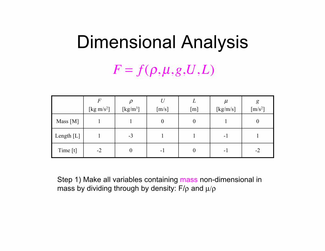
Dimensional Analysis
F = f (!,µ,g,U,L)
F [kg m/s2]
ρ
[kg/m3] U
[m/s] L
[m] µ
[kg/m/s] g
[m/s2]
Mass [M] 1 1 0 0 1 0
Length [L] 1 -3 1 1 -1 1
Time [t] -2 0 -1 0 -1 -2
Step 1) Make all variables containing mass non-dimensional in mass by dividing through by density: F/ρ and µ/ρ

Dimensional AnalysisF
!= f (
µ
!,g,U,L)
Mass [M] 0
F/ρ
[m4/s2]
0
ρ/ρ
[--]
0
U [m/s]
0
L [m]
0
µ/ρ
[m2/s]
0
g [m/s2]
Length [L] 4 0 1 1 2 1
Time [t] -2 0 -1 0 -1 -2
Step 2) Rewrite Matrix deleting density column and mass row

Dimensional AnalysisF
!= f (
µ
!,g,U,L)
0
1
L [m]
-1
2
µ/ρ
[m2/s]
-2
1
g [m/s2]
-1 -2 Time [t]
14Length [L]
U [m/s]
F/ρ
[m4/s2]
Step 3) Non-dimensionalize all variables containing time, using velocity: F/ρU2 and µ/ρU and g/U2
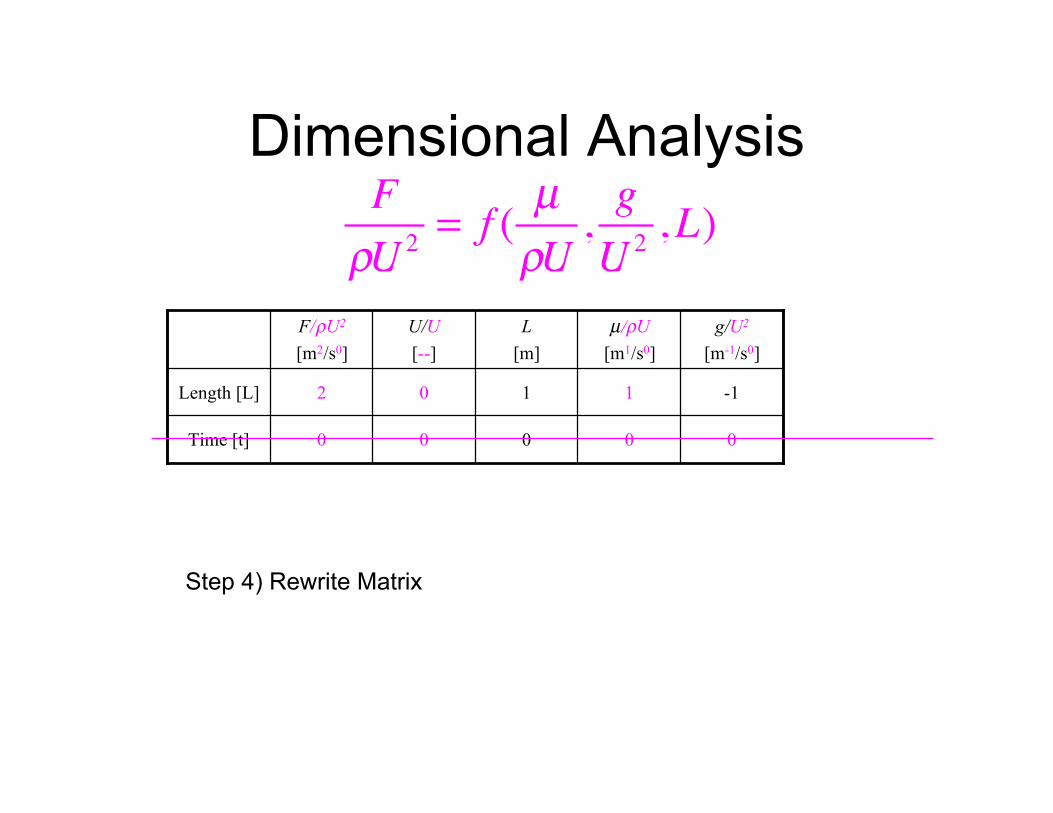
Dimensional AnalysisF
!U 2= f (
µ
!U,g
U2,L)
0
1
L [m]
0
1
µ/ρU [m1/s0]
0
-1
g/U2
[m-1/s0]
00Time [t]
02Length [L]
U/U [--]
F/ρU2
[m2/s0]
Step 4) Rewrite Matrix
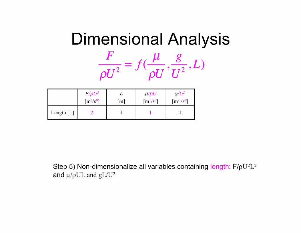
Dimensional AnalysisF
!U 2= f (
µ
!U,g
U2,L)
F/ρU2
[m2/s0] L
[m] µ/ρU
[m1/s0] g/U2
[m-1/s0]
Length [L] 2 1 1 -1
Step 5) Non-dimensionalize all variables containing length: F/ρU2L2
and µ/ρUL and gL/U2
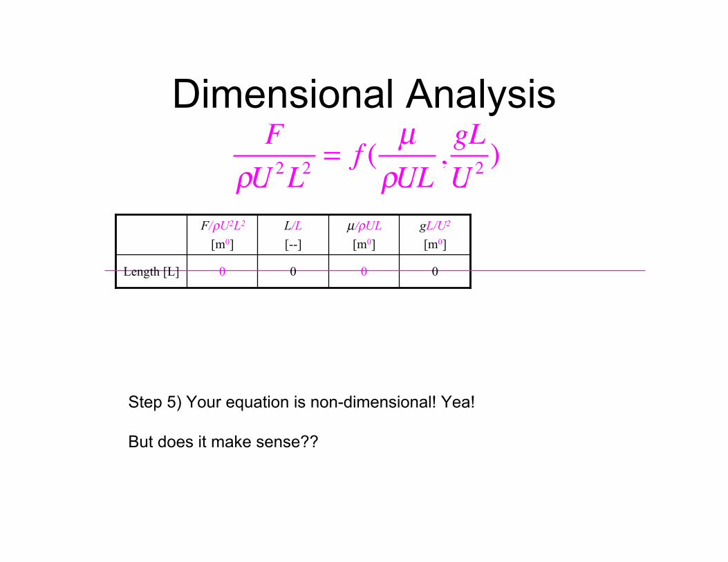
Dimensional AnalysisF
!U 2L2= f (
µ
!UL,gL
U2)
F/ρU2L2 L/L µ/ρUL gL/U2
[m0] [--] [m0] [m0]
Length [L] 0 0 0 0
Step 5) Your equation is non-dimensional! Yea!
But does it make sense??
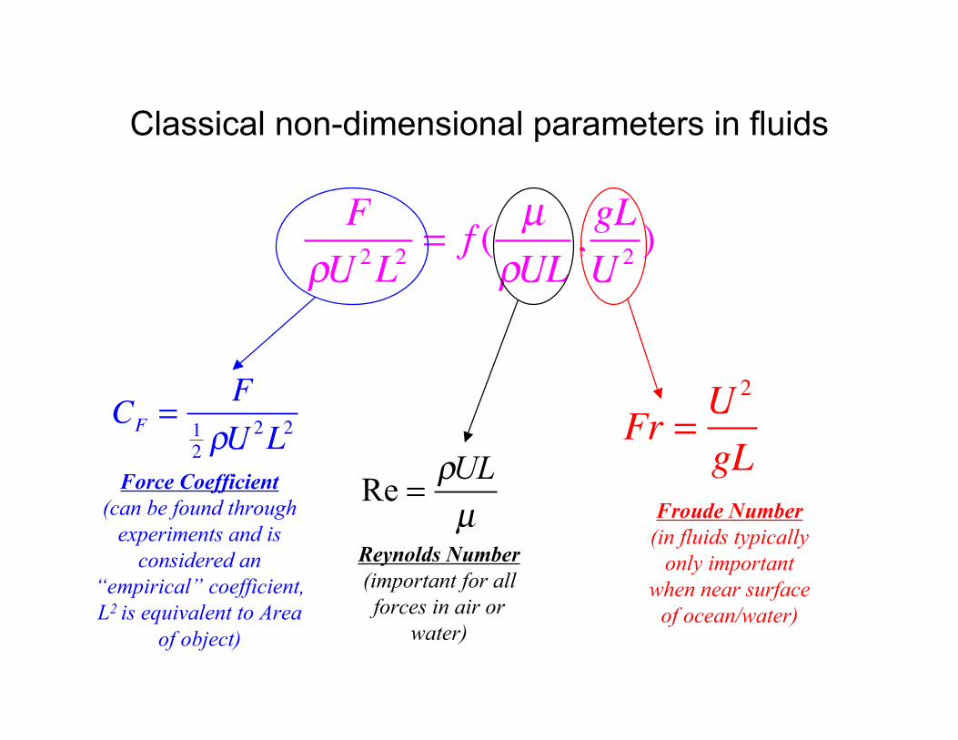
Classical non-dimensional parameters in fluids
F
!U 2L2= f (
µ
!UL,gL
U2)
CF=
F
1
2!U 2
L2
Force Coefficient
Fr =U
2
gL
(can be found through experiments and is
considered an “empirical” coefficient, L2 is equivalent to Area
of object)
Re =!UL
µ Froude Number (in fluids typically
Reynolds Number only important(important for all when near surface forces in air or of ocean/water)
water)