Mini-328 User Manual - One Byte CPU · Mini-328 to Atmega328 Pin Mapping DIP # Mini-328 Name...
11
Ω - Omega MCU Systems Copyright 2011 Mini-328 Breadboard/Embedded MCU Board User Manual
Transcript of Mini-328 User Manual - One Byte CPU · Mini-328 to Atmega328 Pin Mapping DIP # Mini-328 Name...
ΩΩΩΩ - Omega MCU Systems Copyright 2011
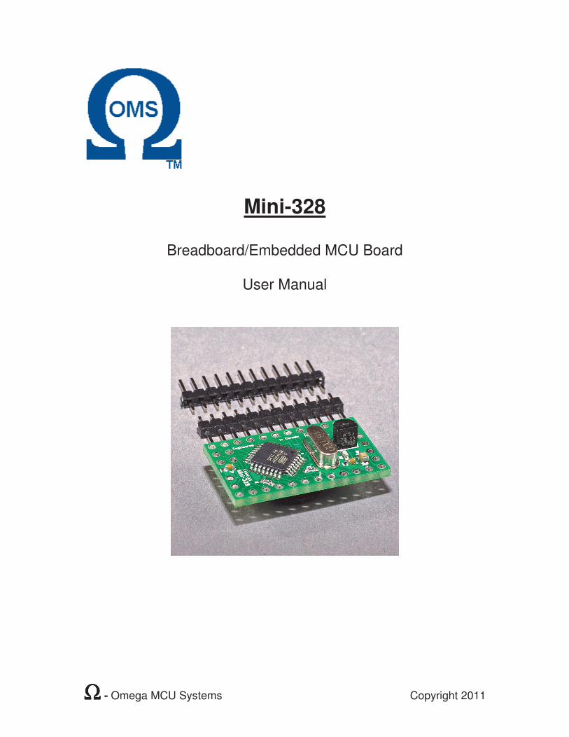
Mini-328
Breadboard/Embedded MCU Board
User Manual
ΩΩΩΩ - Omega MCU Systems Page 1 Copyright 2011
Contents Introduction ...........................................................................................................2
Mini-328 features:..............................................................................................2 Pin Configuration and Description.........................................................................3
Pin Functions.....................................................................................................3 Mini-328 to Atmega328 Pin Mapping ................................................................4
Usage ...................................................................................................................5 1. Connections for power ..................................................................................5 2. Connections for Programming.......................................................................5 3. Programming the Mini-328 ............................................................................6
Additional Information ...........................................................................................7 Using the OMS-Mini-328 with the OMS Dev-Duino...........................................7 Adding the OMS Mini-328 to the Arduino IDE ...................................................8 In Circuit Serial Programming/In System Programming (ICSP/ISP)..................9
Specifications......................................................................................................10 Power Requirements.......................................................................................10 Communications requirements........................................................................10 Supply Capability.............................................................................................10 Physical ...........................................................................................................10
ΩΩΩΩ - Omega MCU Systems Page 2 Copyright 2011
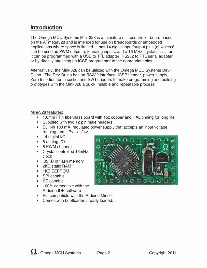
Introduction The Omega MCU Systems Mini-328 is a miniature microcontroller board based on the ATmega328 and is intended for use on breadboards or embedded applications where space is limited. It has 14 digital input/output pins (of which 6 can be used as PWM outputs), 8 analog inputs, and a 16 MHz crystal oscillator. It can be programmed with a USB to TTL adapter, RS232 to TTL serial adapter or by directly attaching an ICSP programmer to the appropriate pins. Alternatively, the Mini-328 can be utilized with the Omega MCU Systems Dev-Duino. The Dev-Duino has an RS232 interface, ICSP header, power supply, Zero Insertion force socket and SVG headers to make programming and building prototypes with the Mini-328 a quick, reliable and repeatable process. Mini-328 features:
• 1.6mm FR4 fiberglass board with 1oz copper and HAL tinning for long life
• Supplied with two 12 pin male headers
• Built-in 100 mA, regulated power supply that accepts an input voltage ranging from +7v to +24v.
• 14 digital I/O
• 8 analog I/O
• 6 PWM channels
• Crystal controlled 16mHz clock
• 32KB of flash memory
• 2KB static RAM
• 1KB EEPROM
• SPI capable
• I2C capable
• 100% compatible with the Arduino IDE software
• Pin compatible with the Arduino Mini 04
• Comes with bootloader already loaded.
ΩΩΩΩ - Omega MCU Systems Page 3 Copyright 2011
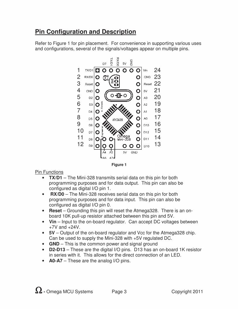
Pin Configuration and Description Refer to Figure 1 for pin placement. For convenience in supporting various uses and configurations, several of the signals/voltages appear on multiple pins.
Figure 1
Pin Functions
• TX/D1 – The Mini-328 transmits serial data on this pin for both programming purposes and for data output. This pin can also be configured as digital I/O pin 1.
• RX/D0 – The Mini-328 receives serial data on this pin for both programming purposes and for data input. This pin can also be configured as digital I/O pin 0.
• Reset – Grounding this pin will reset the Atmega328. There is an on-board 10K pull-up resistor attached between this pin and 5V.
• Vin – Input to the on-board regulator. Can accept DC voltages between +7V and +24V.
• 5V – Output of the on-board regulator and Vcc for the Atmega328 chip. Can be used to supply the Mini-328 with +5V regulated DC.
• GND – This is the common power and signal ground
• D2-D13 – These are the digital I/O pins. D13 has an on-board 1K resistor in series with it. This allows for the direct connection of an LED.
• A0-A7 – These are the analog I/O pins.
1 2 3 4 5 6 7 8 9 10 11 12
24 23 22 21 20 19 18 17 16 15 14 13
ΩΩΩΩ - Omega MCU Systems Page 4 Copyright 2011
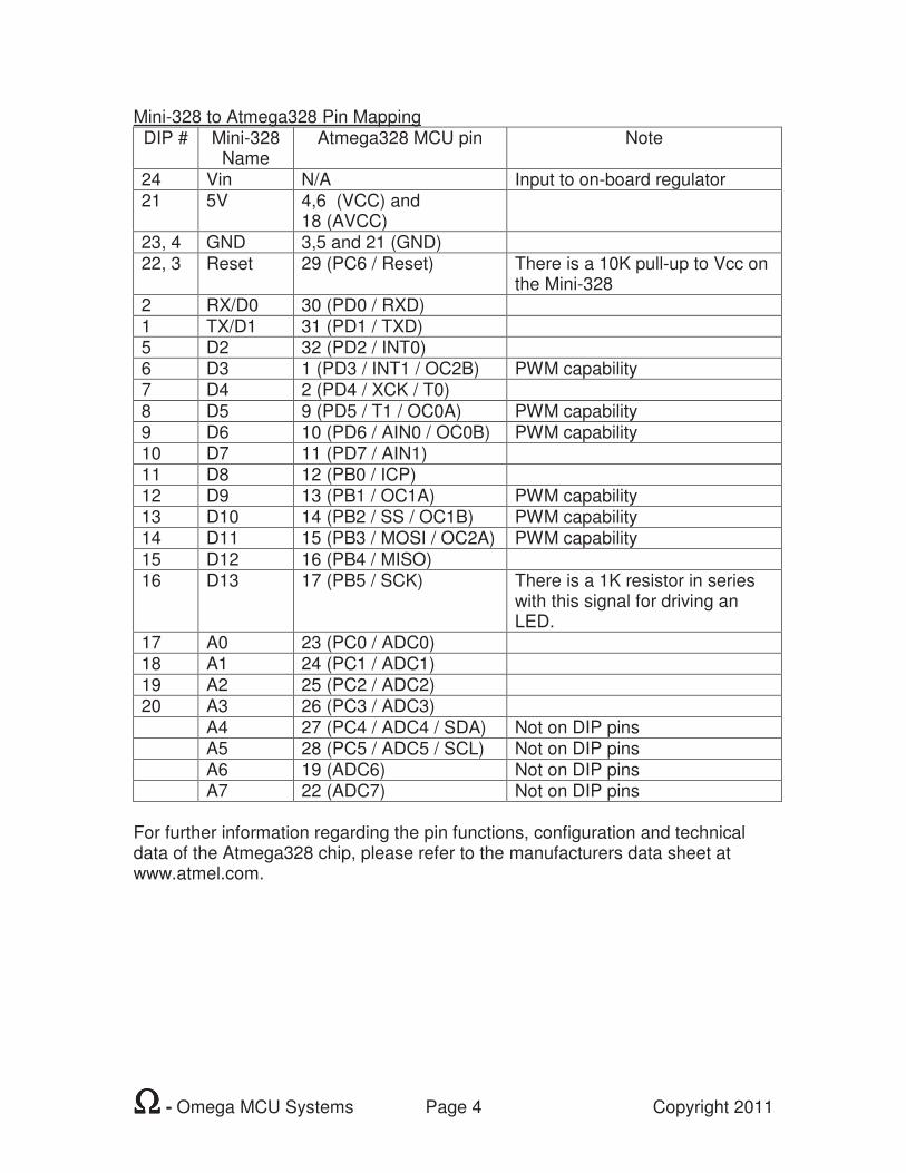
Mini-328 to Atmega328 Pin Mapping DIP # Mini-328
Name Atmega328 MCU pin Note
24 Vin N/A Input to on-board regulator 21 5V 4,6 (VCC) and
18 (AVCC)
23, 4 GND 3,5 and 21 (GND)
22, 3 Reset 29 (PC6 / Reset) There is a 10K pull-up to Vcc on the Mini-328
2 RX/D0 30 (PD0 / RXD) 1 TX/D1 31 (PD1 / TXD) 5 D2 32 (PD2 / INT0) 6 D3 1 (PD3 / INT1 / OC2B) PWM capability 7 D4 2 (PD4 / XCK / T0)
8 D5 9 (PD5 / T1 / OC0A) PWM capability 9 D6 10 (PD6 / AIN0 / OC0B) PWM capability 10 D7 11 (PD7 / AIN1) 11 D8 12 (PB0 / ICP) 12 D9 13 (PB1 / OC1A) PWM capability 13 D10 14 (PB2 / SS / OC1B) PWM capability 14 D11 15 (PB3 / MOSI / OC2A) PWM capability
15 D12 16 (PB4 / MISO) 16 D13 17 (PB5 / SCK) There is a 1K resistor in series
with this signal for driving an LED.
17 A0 23 (PC0 / ADC0) 18 A1 24 (PC1 / ADC1) 19 A2 25 (PC2 / ADC2) 20 A3 26 (PC3 / ADC3)
A4 27 (PC4 / ADC4 / SDA) Not on DIP pins A5 28 (PC5 / ADC5 / SCL) Not on DIP pins A6 19 (ADC6) Not on DIP pins A7 22 (ADC7) Not on DIP pins
For further information regarding the pin functions, configuration and technical data of the Atmega328 chip, please refer to the manufacturers data sheet at www.atmel.com.
ΩΩΩΩ - Omega MCU Systems Page 5 Copyright 2011
Usage 1. Connections for power This can be a regulated +5V power source connected to one of the 5V pins of the Mini-328. Or, a +7V to +24V DC power source such as a battery or DC power adapter connected to the Vin pin. Of course, one of the ground pins on the Mini-328 must be connected to the ground of the power source as well. If the Mini-328 will be powered from a ‘noisy’ power source such as an automotive electrical system it is recommended that a sufficient LC filter be utilized. Such LC filters usually consist of a large choke and an electrolytic capacitor. They can be found at most automotive audio dealers. 2. Connections for Programming
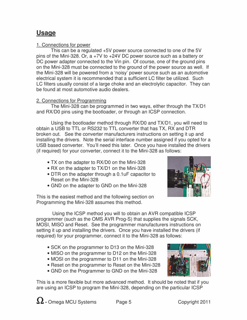
The Mini-328 can be programmed in two ways, either through the TX/D1 and RX/D0 pins using the bootloader, or through an ICSP connection. Using the bootloader method through RX/D0 and TX/D1, you will need to obtain a USB to TTL or RS232 to TTL converter that has TX, RX and DTR broken out. See the converter manufacturers instructions on setting it up and installing the drivers. Note the serial interface number assigned if you opted for a USB based converter. You’ll need this later. Once you have installed the drivers (if required) for your converter, connect it to the Mini-328 as follows:
• TX on the adapter to RX/D0 on the Mini-328
• RX on the adapter to TX/D1 on the Mini-328
• DTR on the adapter through a 0.1uF capacitor to Reset on the Mini-328
• GND on the adapter to GND on the Mini-328 This is the easiest method and the following section on Programming the Mini-328 assumes this method.
Using the ICSP method you will to obtain an AVR compatible ICSP programmer (such as the OMS AVR Prog-S) that supplies the signals SCK, MOSI, MISO and Reset. See the programmer manufacturers instructions on setting it up and installing the drivers. Once you have installed the drivers (if required) for your programmer, connect it to the Mini-328 as follows:
• SCK on the programmer to D13 on the Mini-328
• MISO on the programmer to D12 on the Mini-328
• MOSI on the programmer to D11 on the Mini-328
• Reset on the programmer to Reset on the Mini-328
• GND on the Programmer to GND on the Mini-328 This is a more flexible but more advanced method. It should be noted that if you are using an ICSP to program the Mini-328, depending on the particular ICSP
ΩΩΩΩ - Omega MCU Systems Page 6 Copyright 2011
programmer, it might require some simple configuration of the Arduino IDE for proper operation. Also, see the section later in this document for further information on ICSP. 3. Programming the Mini-328
At this point you are ready to begin downloading programs to your Mini-328. The OMS Mini-328 has been designed to work with the Arduino IDE v1.0.x, which is available free at http://arduino.cc/hu/Main/Software. Please refer to the documentation there on installing and setting up the Arduino IDE.
To download sketches (Arduino speak for program) to the OMS Mini-328 you will need to choose and appropriate board and Serial Port within the Arduino IDE. Here’s how to do this:
• Start the Arduino IDE
• Go to the ‘Tools’ menu o Select ‘Board’
Select ‘Arduino Mini w/ Atmega328’
• Got to the ‘Tools’ menu o Select ‘Serial Port’
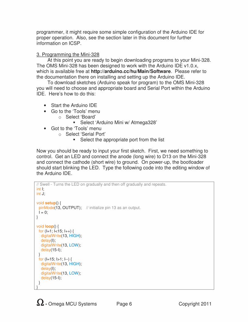
Select the appropriate port from the list Now you should be ready to input your first sketch. First, we need something to control. Get an LED and connect the anode (long wire) to D13 on the Mini-328 and connect the cathode (short wire) to ground. On power-up, the bootloader should start blinking the LED. Type the following code into the editing window of the Arduino IDE. // Swell - Turns the LED on gradually and then off gradually and repeats. int I; int J; void setup() pinMode(13, OUTPUT); // initialize pin 13 as an output. I = 0; void loop() for (I=1; I<15; I++) digitalWrite(13, HIGH); delay(I); digitalWrite(13, LOW); delay(15-I); for (I=15; I>1; I--) digitalWrite(13, HIGH); delay(I); digitalWrite(13, LOW); delay(15-I);
ΩΩΩΩ - Omega MCU Systems Page 7 Copyright 2011
Once you have it typed in, click on the Upload button. After a couple seconds the message window should display a message like ‘Binary sketch size: 1214 bytes (of a 30720 byte maximum)’. At this point the compiled program will be uploaded to the Mini-328. Note the change in how the LED behaves. The function of this program can also be accomplished using Pulse Width modulation (PWM). As a next step, try to re-write this program using PWM and the anlogWrite() function. You can find out more about analogWrite() and all the Arduino language constructs at http://arduino.cc/en/Reference/HomePage. Remember, you’ll need to use a different pin for output and you’ll need a current limiting resistor. 1K ohm is ideal.
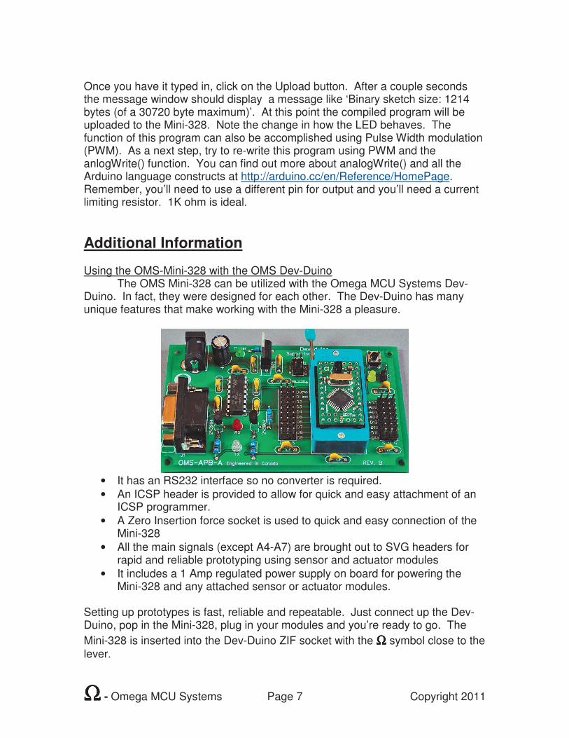
Additional Information Using the OMS-Mini-328 with the OMS Dev-Duino The OMS Mini-328 can be utilized with the Omega MCU Systems Dev-Duino. In fact, they were designed for each other. The Dev-Duino has many unique features that make working with the Mini-328 a pleasure.
• It has an RS232 interface so no converter is required.
• An ICSP header is provided to allow for quick and easy attachment of an ICSP programmer.
• A Zero Insertion force socket is used to quick and easy connection of the Mini-328
• All the main signals (except A4-A7) are brought out to SVG headers for rapid and reliable prototyping using sensor and actuator modules
• It includes a 1 Amp regulated power supply on board for powering the Mini-328 and any attached sensor or actuator modules.
Setting up prototypes is fast, reliable and repeatable. Just connect up the Dev-Duino, pop in the Mini-328, plug in your modules and you’re ready to go. The
Mini-328 is inserted into the Dev-Duino ZIF socket with the ΩΩΩΩ symbol close to the lever.
ΩΩΩΩ - Omega MCU Systems Page 8 Copyright 2011
Adding the OMS Mini-328 to the Arduino IDE If wish, you can optionally add the OMS Mini-328 to your Arduino IDE. It’s not that difficult. Here is how to do it:
• Start the Arduino IDE
• Go to the ‘File’ menu o Select ‘Preferences’ o Make a note the Sketchbook Location folder o Click ‘Cancel’
• Close the Arduino IDE
• Right click ‘My Computer’ in Windows o Select ‘Explore’ o Navigate to the Sketchbook Location folder o See if there is a folder named ‘hardware’ in the folder view
If not, create it o Navigate to the ‘hardware’ folder o Create a new folder named ‘OMS Mini-328’ o Navigate to the ‘OMS Mini-328’ folder o Create a new text document named ‘boards.txt’ o Open boards.txt and copy or type in the text below o Save boards.txt o Exit windows Explorer
• Start the Arduino IDE
• Go to the ‘Tools’ menu o Select ‘Board’ o OMS Mini-328 should now be in the list
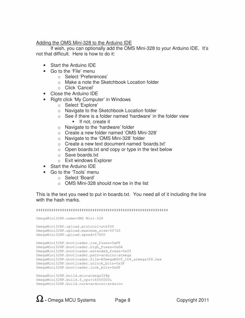
This is the text you need to put in boards.txt. You need all of it including the line with the hash marks. #############################################################
OmegaMini328P.name=OMS Mini-328
OmegaMini328P.upload.protocol=stk500
OmegaMini328P.upload.maximum_size=30720
OmegaMini328P.upload.speed=57600
OmegaMini328P.bootloader.low_fuses=0xFF
OmegaMini328P.bootloader.high_fuses=0xDA
OmegaMini328P.bootloader.extended_fuses=0x05
OmegaMini328P.bootloader.path=arduino:atmega
OmegaMini328P.bootloader.file=ATmegaBOOT_168_atmega328.hex
OmegaMini328P.bootloader.unlock_bits=0x3F
OmegaMini328P.bootloader.lock_bits=0x0F
OmegaMini328P.build.mcu=atmega328p
OmegaMini328P.build.f_cpu=16000000L
OmegaMini328P.build.core=arduino:arduino
ΩΩΩΩ - Omega MCU Systems Page 9 Copyright 2011
In Circuit Serial Programming/In System Programming (ICSP/ISP)
ICSP is a method by which an MCU (an AVR in this case) can be directly programmed while still in a circuit. In the AVR world, the programmer is known as the master and the chip to be programmed as the slave. The signals used are MOSI (Master Out – Slave In), MISO (Master In – Slave Out) and SCK (Serial Clock), which is supplied by the master or programmer. Add to this a reset line, to reset the MCU, Vcc by which the programmer can power the MCU and a ground and you have all the signals of a standard AVR ICSP interface.. This can be used, in conjunction with a an ICSP programmer, such as the OMS AVR Prog-S, to program the MCU on board the Mini-328. Since the ICSP protocol is built into the Atmega chips used on this board, it is not dependant on using the bootloader and does not require the serial interface. For this reason, it can be used to program, or ‘burn’ the bootloader onto a new or erased MCU. It can also be used an alternative method of getting code onto the MCU. This is particularly useful in cases where the code is larger than will fit onto the MCU if the bootloader is present. Simply erase the chip and burn the code on using ICSP. Not using the bootloader will give approximately 2k more flash space. There are many dozens of ICSP/ISP programmers available and an equal number of software options. AVRdude and PonyProg are popular and free of charge. Note: Arduino and Arduino Mini are trademarks of the Arduino project team. Arduino Pro Mini is a trademark of SparkFun Electronics.
ΩΩΩΩ - Omega MCU Systems Page 10 Copyright 2011
Specifications Power Requirements
• Supply Voltage : (Vin pin) +7V to +24V DC or (5V pin) Regulated +5V DC
• Supply Current : Typically between 18ma and 22ma with the MCU only, while running the bootloader.
NOTE: Supply voltage on Vin should never exceed +24V dc. Observe polarity. Check before attaching the power source. Communications requirements
• Interface Types: TTL level serial, standard ICSP, SPI and I2C
• Connections: o TTL level serial through RX/D0, TX/D1 and GND o ICSP through D11(MOSI), D12(MISO), D13(SCK) Reset and GND o SPI through D10(SS), D11(MOSI), D12(MISO), D13(SCK) and
GND o I2C through A4(SDA), A5(SCL), and GND
Supply Capability Regulated Voltage: 5V (4.8V – 5.2V) Maximum current : approximately 60 mA, allowing for the MCU’s own
requirements. Physical
• Length: 31mm
• Width: 18mm
• Height: 15mm (with headers), 8mm (no headers)
• Weight: <6g (with headers), <5g (no headers)
• Operating Temp. 0oC – 85oC OMS PO Box 74 Bracebridge, ON Canada P1L 1T5