MicroTech ΙΙΙΙΙΙ Controller With Starter...
100
Operating Manual OM CentrifMicro II-5 Group: Chiller Part Number: 331374901 Effective: March 2011 Supersedes: November 2010 MicroTech ΙΙ Controller With Starter Information For Centrifugal Chillers and Templifiers Models WSC, WDC, WCC, HSC, TSC Software Version: WCFU3UU04C/D/E OITS Version: 2.05.03
Transcript of MicroTech ΙΙΙΙΙΙ Controller With Starter...
Operating Manual OM CentrifMicro II-5
Group: Chiller
Part Number: 331374901
Effective: March 2011
Supersedes: November 2010
MicroTech ΙΙΙΙΙΙΙΙ Controller
With Starter Information
For Centrifugal Chillers and Templifiers
Models WSC, WDC, WCC, HSC, TSC
Software Version: WCFU3UU04C/D/E
OITS Version: 2.05.03
2 OM CentrifMicro II-5
Table of Contents
Introduction ............................................... 3
Features of the Control Panel................... 4
General Description................................... 5
Component Description ............................ 6
Operator Interface Touch Screen ...........................6 Unit/Compressor Controller Description...............6 Software.................................................................7 Unit Controller.......................................................7 Compressor Controller ..........................................8 Guardister Board ................................................9 Signal Converter Board .........................................9 Transducer Converter Board..................................9 PLAN Isolator .......................................................9 Field Wiring Diagram..........................................10
Dual/Multi-Chiller Operation ................ 12
Multiple Chiller Setup .........................................12 WCC Settings ......................................................15
Ice Mode Operation................................. 16
Operator Interface Touch Screen........... 16
Navigation ...........................................................16 Screen Descriptions .............................................18 VIEW Screens .....................................................18 SET Screens.........................................................23 SERVICE Screen.................................................37 HISTORY Screens...............................................38 Download from the USB .....................................39 ACTIVE ALARM Screen....................................40
Unit Controller......................................... 43
Navigating ...........................................................43 Screen Descriptions .............................................46 SET Screens.........................................................49
Unit Controller Setpoints..................................... 51
Compressor Controller ........................... 61
Navigating ........................................................... 61 Compressor Controller Setpoints......................... 62
Optional Starter Screens......................... 67
Low Voltage Starters, 200 – 600 Volts.... 68
General ................................................................ 68 LED Display........................................................ 69 Faults and Alarms ................................................ 74 Troubleshooting................................................... 77 Preventive Maintenance ...................................... 82
Medium/High Voltage Starters, 2300V
– 7.2KV..................................................... 83
View Parameters.................................................. 84 Set Parameters ..................................................... 84 Quick Start........................................................... 86 Troubleshooting................................................... 88 Fault/Log Codes .................................................. 90 LED Diagnostics ................................................. 93 Preventive Maintenance ...................................... 93
Sequence of Operation............................ 94
Unit Operation..................................................... 94
Operating the Chiller Control System... 96
Interface Panel On/Off ........................................ 96 Start/Stop Unit..................................................... 96 Change Setpoints ................................................. 97 Alarms ................................................................. 97 Component Failure .............................................. 97 Standby Power..................................................... 97
Maintenance Schedule ............................ 98
McQuay" and MicroTech II are registered trademarks of McQuay International 2005 McQuay International
"Illustrations and information cover McQuay International products at the time of publication and we reserve the right to make changes in design and construction at anytime without notice."
Manufactured in an ISO certified facility.
ETL applies only to models
WSC, WDC
OM Centrif Micro ΙΙ-5 3
Introduction This manual provides operating, maintenance and troubleshooting information for McQuay
centrifugal chillers with MicroTech ΙΙ control and for the majority of starters used on McQuay
centrifugal chillers.
Software Version
Software Code: WCFU3UU04C/D/E
Notations stating previous content are made when a new version changes a previous value or
statement.
WARNING
Electric shock hazard. Can cause personal injury or equipment damage. This equipment must be properly grounded. Connections to and service of the
MicroTech control panel must be performed only by personnel that are knowledgeable
in the operation of the equipment being controlled.
CAUTION
Static sensitive components. A static discharge while handling electronic circuit boards can damage components. Discharge any static electrical charge
by touching the bare metal inside the control panel before performing any service work. Never unplug any cables, circuit board terminal blocks,
or power plugs while power is applied to the panel.
NOTICE
This equipment generates, uses and can radiate radio frequency energy and, if not installed and used in accordance with this instruction manual,
may cause interference to radio communications. Operation of this equipment in a residential area is likely to cause harmful interference in which case the user
will be required to correct the interference at his own expense. McQuay International Corporation disclaims any liability resulting
from any interference or for the correction thereof.
CAUTION
Do not install any non-McQuay authorized software or alter operating systems in any unit microprocessor, including the interface panel. Failure to do so can cause
malfunction of the control system and possible equipment damage.
Temperature and Humidity Limits
The MicroTech ΙΙ controller is designed to operate within an ambient temperature range of 20°F to
130°F (-7°C to 54°C) with a maximum relative humidity of 95% (non-condensing).
4 OM Centrif Micro ΙΙ-5
Features of the Control Panel
• Control of leaving chilled water within a ±0.5°F (±0.3°C) tolerance. Systems with a large water
volume and relatively slow load changes can do better.
• Readout of the following temperature and pressure readings:
• Entering and leaving chilled water temperature
• Entering and leaving condenser water temperature
• Saturated evaporator refrigerant temperature and pressure
• Saturated condenser temperature and pressure
• Suction line, liquid line and discharge line temperatures - calculated superheat for discharge
and suction lines – calculated subcooling for liquid line
• Oil sump temperature - oil feed temperature and pressure
• Optional condenser heat recovery temperature
• Automatic control of primary and standby evaporator and condenser pumps.
• Control of up to 4 stages of cooling tower fans plus modulating bypass valve and/or tower fan
VFD.
• The controller will store and display key historic operating data for recall in a graphic format on
the screen. Data can also be exported for archival purposes via a USB port.
• Three levels of security protection against unauthorized changing of setpoints and other control
parameters.
• Warning and fault diagnostics to inform operators of warning and fault conditions in plain
language. Al1 warnings, problems and faults are time and date stamped so there is no guessing
of when the fault condition occurred. In addition, the operating conditions that existed just prior
to shutdown can be recalled to aid in isolating the cause of the problem.
• Twenty-five latest faults are displayed on the unit controller, eight can be displayed on the touch
screen. Data can be exported for archival purposes via a 3.5-inch floppy drive.
• Soft loading feature reduces electrical consumption and peak demand charges during loop
pulldown.
• Adjustable load pull-down rate reduces under-shoot during loop pulldown.
• Remote input signals for chilled water reset, demand limiting, unit enable.
• Manual control mode allows the service technician to command the unit to different operating
states. Useful for system checkout.
• BAS communication capability via LONMARK, Modbus or BACnet standard protocols for
BAS manufacturers.
• Service Test mode for troubleshooting controller hardware.
• Pressure transducers for direct reading of system pressures. Preemptive control of high motor
amps, low evaporator pressure conditions and high discharge temperature takes corrective action
prior to a fault trip.
OM Centrif Micro ΙΙ-5 5
General Description
General Description
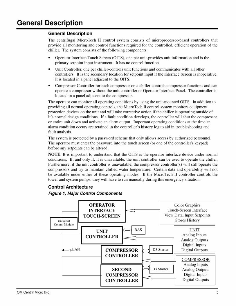
The centrifugal MicroTech ΙΙ control system consists of microprocessor-based controllers that
provide all monitoring and control functions required for the controlled, efficient operation of the
chiller. The system consists of the following components:
• Operator Interface Touch Screen (OITS), one per unit-provides unit information and is the
primary setpoint input instrument. It has no control function.
• Unit Controller, one per chiller-controls unit functions and communicates with all other
controllers. It is the secondary location for setpoint input if the Interface Screen is inoperative.
It is located in a panel adjacent to the OITS.
• Compressor Controller for each compressor on a chiller-controls compressor functions and can
operate a compressor without the unit controller or Operator Interface Panel. The controller is
located in a panel adjacent to the compressor.
The operator can monitor all operating conditions by using the unit-mounted OITS. In addition to
providing all normal operating controls, the MicroTech II control system monitors equipment
protection devices on the unit and will take corrective action if the chiller is operating outside of
it’s normal design conditions. If a fault condition develops, the controller will shut the compressor
or entire unit down and activate an alarm output. Important operating conditions at the time an
alarm condition occurs are retained in the controller’s history log to aid in troubleshooting and
fault analysis.
The system is protected by a password scheme that only allows access by authorized personnel.
The operator must enter the password into the touch screen (or one of the controller's keypad)
before any setpoints can be altered.
NOTE: It is important to understand that the OITS is the operator interface device under normal
conditions. If, and only if, it is unavailable, the unit controller can be used to operate the chiller.
Furthermore, if the unit controller is unavailable, the compressor controller(s) will still operate the
compressors and try to maintain chilled water temperature. Certain data and operability will not
be available under either of these operating modes. If the MicroTech II controller controls the
tower and system pumps, they will have to run manually during this emergency situation.
Control Architecture
Figure 1, Major Control Components
OPERATOR
INTERFACE
TOUCH-SCREEN
UNIT
CONTROLLER
COMPRESSOR
CONTROLLER
SECOND
COMPRESSOR
CONTROLLER (Dual Compressor
Color Graphics
Touch-Screen Interface
View Data, Input Setpoints
Stores History
UNIT
Analog Inputs
Analog Outputs
Digital Inputs
Digital Outputs
COMPRESSOR
Analog Inputs
Analog Outputs
Digital Inputs
Digital Outputs
BAS
pLAN D3 Starter
D3 Starter
Universal
Comm. Module
6 OM Centrif Micro ΙΙ-5
Component Description
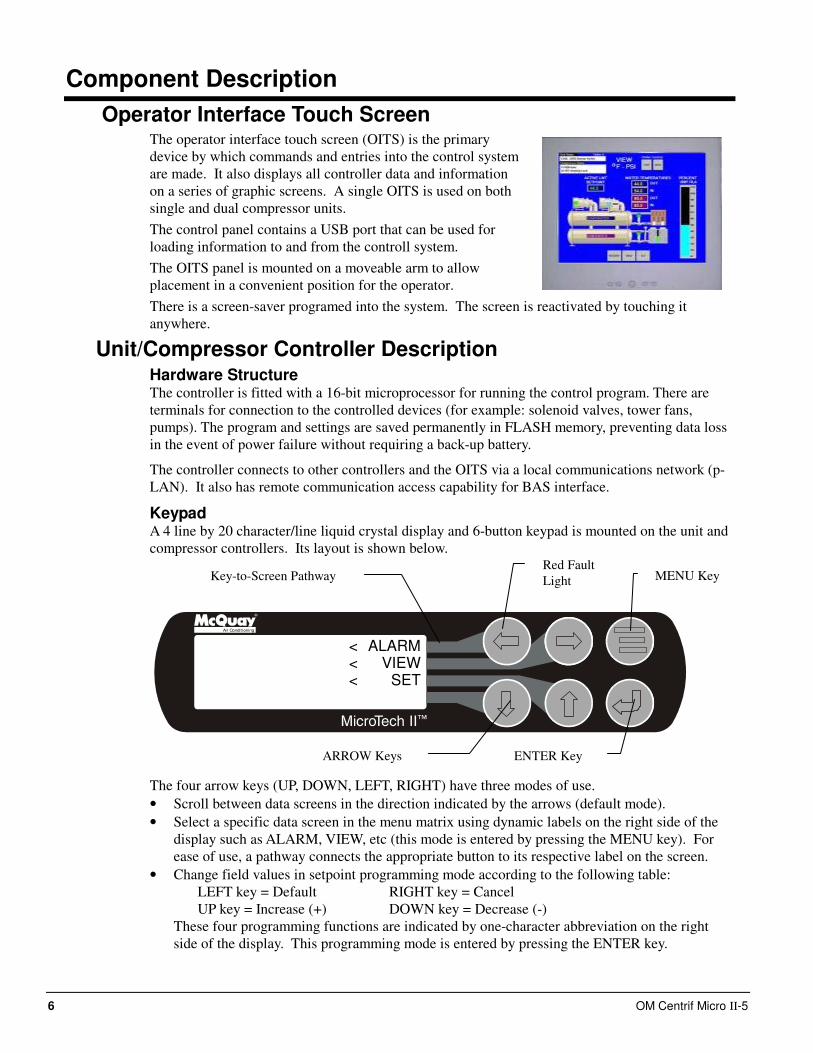
Operator Interface Touch Screen The operator interface touch screen (OITS) is the primary
device by which commands and entries into the control system
are made. It also displays all controller data and information
on a series of graphic screens. A single OITS is used on both
single and dual compressor units.
The control panel contains a USB port that can be used for
loading information to and from the controll system.
The OITS panel is mounted on a moveable arm to allow
placement in a convenient position for the operator.
There is a screen-saver programed into the system. The screen is reactivated by touching it
anywhere.
Unit/Compressor Controller Description Hardware Structure The controller is fitted with a 16-bit microprocessor for running the control program. There are
terminals for connection to the controlled devices (for example: solenoid valves, tower fans,
pumps). The program and settings are saved permanently in FLASH memory, preventing data loss
in the event of power failure without requiring a back-up battery.
The controller connects to other controllers and the OITS via a local communications network (p-
LAN). It also has remote communication access capability for BAS interface.
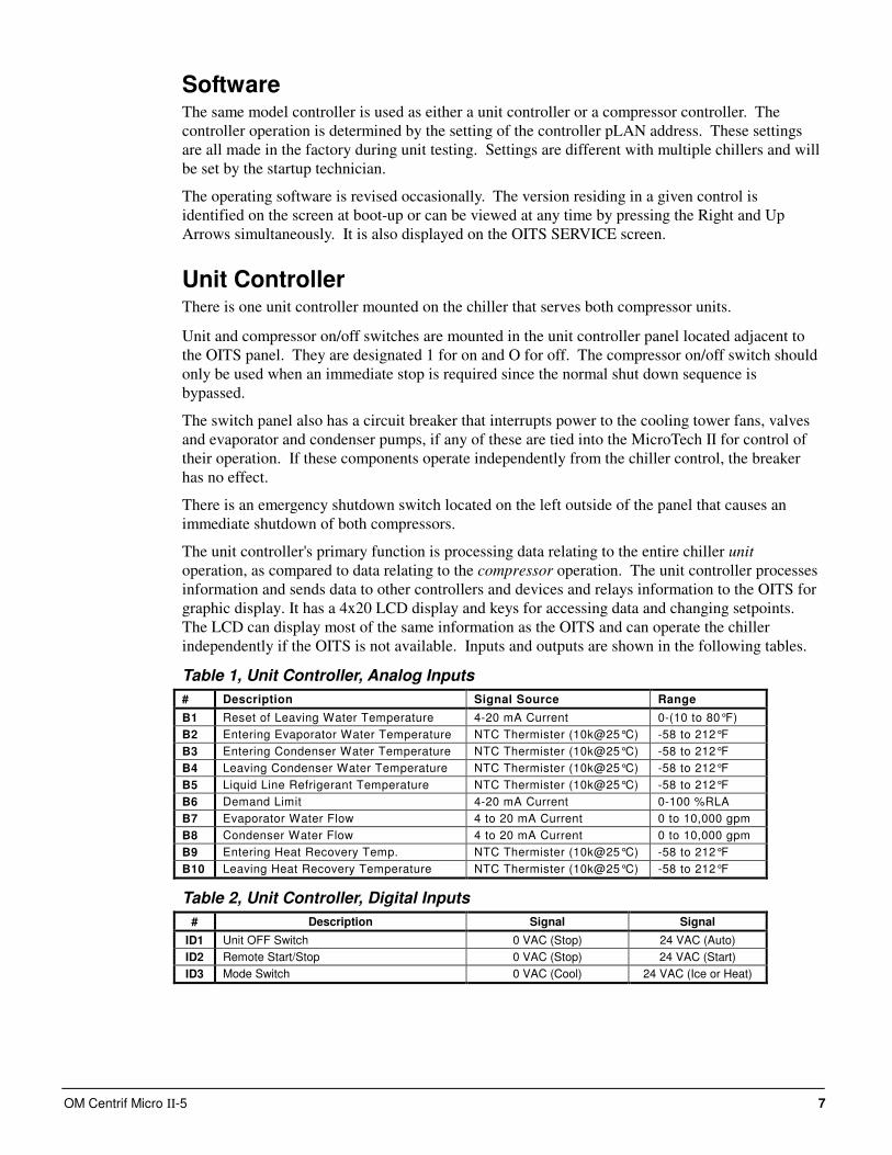
Keypad A 4 line by 20 character/line liquid crystal display and 6-button keypad is mounted on the unit and
compressor controllers. Its layout is shown below.
Air Conditioning
ALARMVIEW
SET
<<<
The four arrow keys (UP, DOWN, LEFT, RIGHT) have three modes of use.
• Scroll between data screens in the direction indicated by the arrows (default mode).
• Select a specific data screen in the menu matrix using dynamic labels on the right side of the
display such as ALARM, VIEW, etc (this mode is entered by pressing the MENU key). For
ease of use, a pathway connects the appropriate button to its respective label on the screen.
• Change field values in setpoint programming mode according to the following table:
LEFT key = Default RIGHT key = Cancel
UP key = Increase (+) DOWN key = Decrease (-)
These four programming functions are indicated by one-character abbreviation on the right
side of the display. This programming mode is entered by pressing the ENTER key.
ENTER Key
MENU Key
ARROW Keys
Key-to-Screen Pathway
Red Fault
Light
OM Centrif Micro ΙΙ-5 7
Software The same model controller is used as either a unit controller or a compressor controller. The
controller operation is determined by the setting of the controller pLAN address. These settings
are all made in the factory during unit testing. Settings are different with multiple chillers and will
be set by the startup technician.
The operating software is revised occasionally. The version residing in a given control is
identified on the screen at boot-up or can be viewed at any time by pressing the Right and Up
Arrows simultaneously. It is also displayed on the OITS SERVICE screen.
Unit Controller There is one unit controller mounted on the chiller that serves both compressor units.
Unit and compressor on/off switches are mounted in the unit controller panel located adjacent to
the OITS panel. They are designated 1 for on and O for off. The compressor on/off switch should
only be used when an immediate stop is required since the normal shut down sequence is
bypassed.
The switch panel also has a circuit breaker that interrupts power to the cooling tower fans, valves
and evaporator and condenser pumps, if any of these are tied into the MicroTech II for control of
their operation. If these components operate independently from the chiller control, the breaker
has no effect.
There is an emergency shutdown switch located on the left outside of the panel that causes an
immediate shutdown of both compressors.
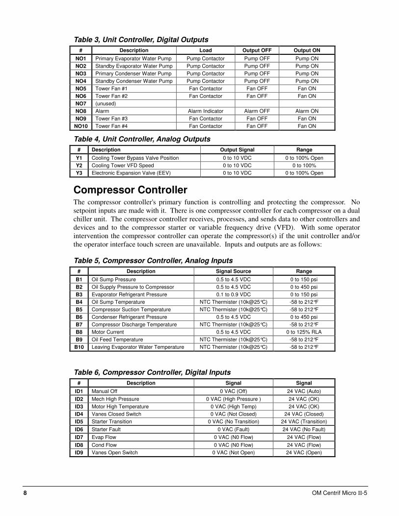
The unit controller's primary function is processing data relating to the entire chiller unit
operation, as compared to data relating to the compressor operation. The unit controller processes
information and sends data to other controllers and devices and relays information to the OITS for
graphic display. It has a 4x20 LCD display and keys for accessing data and changing setpoints.
The LCD can display most of the same information as the OITS and can operate the chiller
independently if the OITS is not available. Inputs and outputs are shown in the following tables.
Table 1, Unit Controller, Analog Inputs
# Description Signal Source Range
B1 Reset of Leaving Water Temperature 4-20 mA Current 0-(10 to 80°F)
B2 Entering Evaporator Water Temperature NTC Thermister (10k@25°C) -58 to 212°F
B3 Entering Condenser Water Temperature NTC Thermister (10k@25°C) -58 to 212°F
B4 Leaving Condenser Water Temperature NTC Thermister (10k@25°C) -58 to 212°F
B5 Liquid Line Refrigerant Temperature NTC Thermister (10k@25°C) -58 to 212°F
B6 Demand Limit 4-20 mA Current 0-100 %RLA
B7 Evaporator Water Flow 4 to 20 mA Current 0 to 10,000 gpm
B8 Condenser Water Flow 4 to 20 mA Current 0 to 10,000 gpm
B9 Entering Heat Recovery Temp. NTC Thermister (10k@25°C) -58 to 212°F
B10 Leaving Heat Recovery Temperature NTC Thermister (10k@25°C) -58 to 212°F
Table 2, Unit Controller, Digital Inputs
# Description Signal Signal
ID1 Unit OFF Switch 0 VAC (Stop) 24 VAC (Auto)
ID2 Remote Start/Stop 0 VAC (Stop) 24 VAC (Start)
ID3 Mode Switch 0 VAC (Cool) 24 VAC (Ice or Heat)
8 OM Centrif Micro ΙΙ-5
Table 3, Unit Controller, Digital Outputs
# Description Load Output OFF Output ON
NO1 Primary Evaporator Water Pump Pump Contactor Pump OFF Pump ON
NO2 Standby Evaporator Water Pump Pump Contactor Pump OFF Pump ON
NO3 Primary Condenser Water Pump Pump Contactor Pump OFF Pump ON
NO4 Standby Condenser Water Pump Pump Contactor Pump OFF Pump ON
NO5 Tower Fan #1 Fan Contactor Fan OFF Fan ON
NO6 Tower Fan #2 Fan Contactor Fan OFF Fan ON
NO7 (unused)
NO8 Alarm Alarm Indicator Alarm OFF Alarm ON
NO9 Tower Fan #3 Fan Contactor Fan OFF Fan ON
NO10 Tower Fan #4 Fan Contactor Fan OFF Fan ON
Table 4, Unit Controller, Analog Outputs
# Description Output Signal Range
Y1 Cooling Tower Bypass Valve Position 0 to 10 VDC 0 to 100% Open
Y2 Cooling Tower VFD Speed 0 to 10 VDC 0 to 100%
Y3 Electronic Expansion Valve (EEV) 0 to 10 VDC 0 to 100% Open
Compressor Controller The compressor controller's primary function is controlling and protecting the compressor. No
setpoint inputs are made with it. There is one compressor controller for each compressor on a dual
chiller unit. The compressor controller receives, processes, and sends data to other controllers and
devices and to the compressor starter or variable frequency drive (VFD). With some operator
intervention the compressor controller can operate the compressor(s) if the unit controller and/or
the operator interface touch screen are unavailable. Inputs and outputs are as follows:
Table 5, Compressor Controller, Analog Inputs
# Description Signal Source Range
B1 Oil Sump Pressure 0.5 to 4.5 VDC 0 to 150 psi
B2 Oil Supply Pressure to Compressor 0.5 to 4.5 VDC 0 to 450 psi
B3 Evaporator Refrigerant Pressure 0.1 to 0.9 VDC 0 to 150 psi
B4 Oil Sump Temperature NTC Thermister (10k@25°C) -58 to 212°F
B5 Compressor Suction Temperature NTC Thermister (10k@25°C) -58 to 212°F
B6 Condenser Refrigerant Pressure 0.5 to 4.5 VDC 0 to 450 psi
B7 Compressor Discharge Temperature NTC Thermister (10k@25°C) -58 to 212°F
B8 Motor Current 0.5 to 4.5 VDC 0 to 125% RLA
B9 Oil Feed Temperature NTC Thermister (10k@25°C) -58 to 212°F
B10 Leaving Evaporator Water Temperature NTC Thermister (10k@25°C) -58 to 212°F
Table 6, Compressor Controller, Digital Inputs
# Description Signal Signal
ID1 Manual Off 0 VAC (Off) 24 VAC (Auto)
ID2 Mech High Pressure 0 VAC (High Pressure ) 24 VAC (OK)
ID3 Motor High Temperature 0 VAC (High Temp) 24 VAC (OK)
ID4 Vanes Closed Switch 0 VAC (Not Closed) 24 VAC (Closed)
ID5 Starter Transition 0 VAC (No Transition) 24 VAC (Transition)
ID6 Starter Fault 0 VAC (Fault) 24 VAC (No Fault)
ID7 Evap Flow 0 VAC (N0 Flow) 24 VAC (Flow)
ID8 Cond Flow 0 VAC (N0 Flow) 24 VAC (Flow)
ID9 Vanes Open Switch 0 VAC (Not Open) 24 VAC (Open)
OM Centrif Micro ΙΙ-5 9
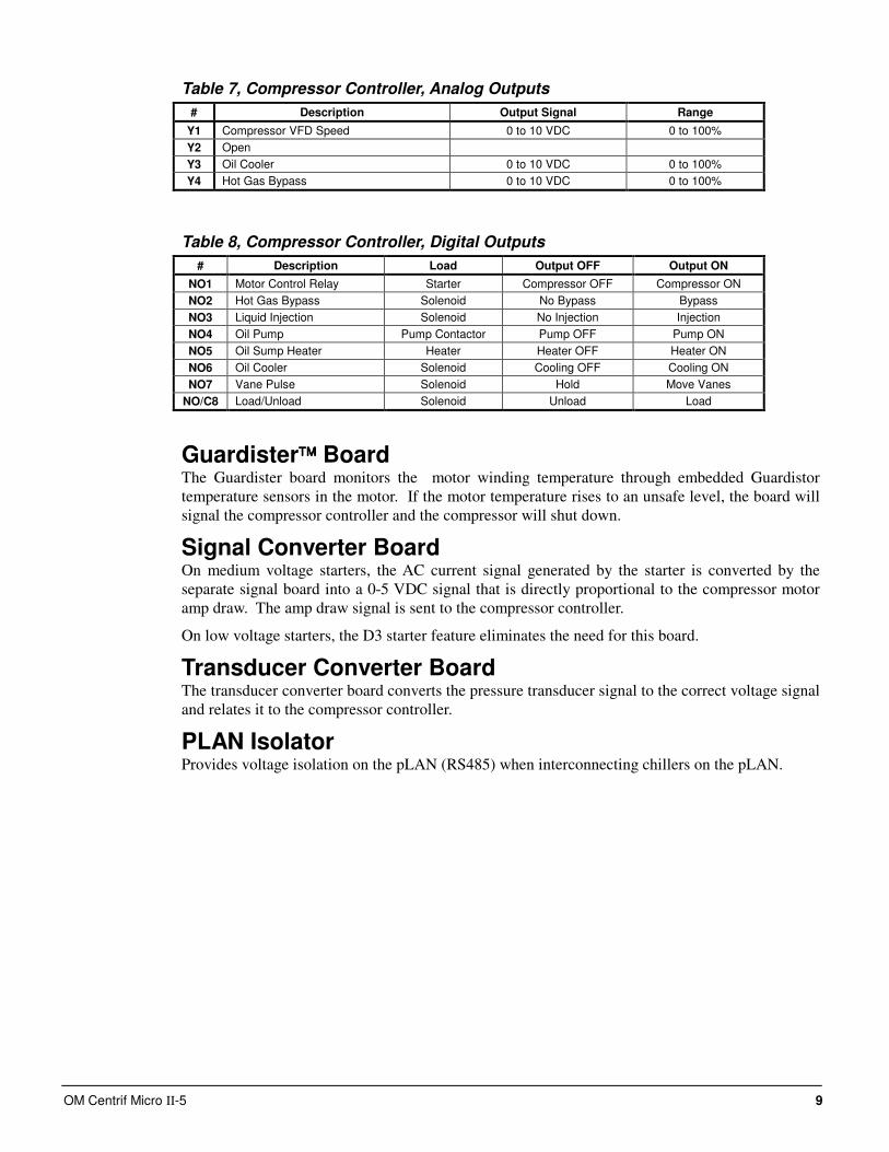
Table 7, Compressor Controller, Analog Outputs
# Description Output Signal Range
Y1 Compressor VFD Speed 0 to 10 VDC 0 to 100%
Y2 Open
Y3 Oil Cooler 0 to 10 VDC 0 to 100%
Y4 Hot Gas Bypass 0 to 10 VDC 0 to 100%
Table 8, Compressor Controller, Digital Outputs
# Description Load Output OFF Output ON
NO1 Motor Control Relay Starter Compressor OFF Compressor ON
NO2 Hot Gas Bypass Solenoid No Bypass Bypass
NO3 Liquid Injection Solenoid No Injection Injection
NO4 Oil Pump Pump Contactor Pump OFF Pump ON
NO5 Oil Sump Heater Heater Heater OFF Heater ON
NO6 Oil Cooler Solenoid Cooling OFF Cooling ON
NO7 Vane Pulse Solenoid Hold Move Vanes
NO/C8 Load/Unload Solenoid Unload Load
Guardister Board The Guardister board monitors the motor winding temperature through embedded Guardistor
temperature sensors in the motor. If the motor temperature rises to an unsafe level, the board will
signal the compressor controller and the compressor will shut down.
Signal Converter Board On medium voltage starters, the AC current signal generated by the starter is converted by the
separate signal board into a 0-5 VDC signal that is directly proportional to the compressor motor
amp draw. The amp draw signal is sent to the compressor controller.
On low voltage starters, the D3 starter feature eliminates the need for this board.
Transducer Converter Board The transducer converter board converts the pressure transducer signal to the correct voltage signal
and relates it to the compressor controller.
PLAN Isolator Provides voltage isolation on the pLAN (RS485) when interconnecting chillers on the pLAN.
10 OM Centrif Micro ΙΙ-5
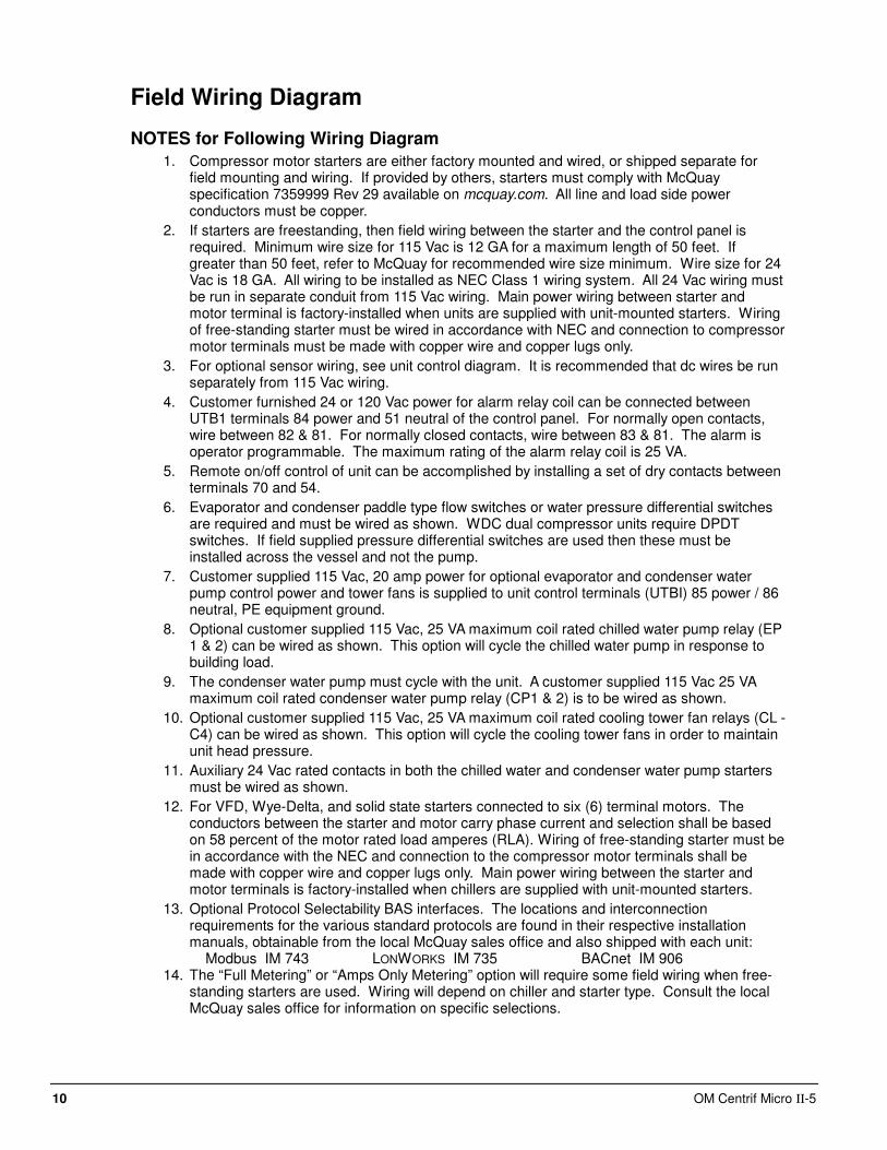
Field Wiring Diagram
NOTES for Following Wiring Diagram
1. Compressor motor starters are either factory mounted and wired, or shipped separate for field mounting and wiring. If provided by others, starters must comply with McQuay specification 7359999 Rev 29 available on mcquay.com. All line and load side power conductors must be copper.
2. If starters are freestanding, then field wiring between the starter and the control panel is required. Minimum wire size for 115 Vac is 12 GA for a maximum length of 50 feet. If greater than 50 feet, refer to McQuay for recommended wire size minimum. Wire size for 24 Vac is 18 GA. All wiring to be installed as NEC Class 1 wiring system. All 24 Vac wiring must be run in separate conduit from 115 Vac wiring. Main power wiring between starter and motor terminal is factory-installed when units are supplied with unit-mounted starters. Wiring of free-standing starter must be wired in accordance with NEC and connection to compressor motor terminals must be made with copper wire and copper lugs only.
3. For optional sensor wiring, see unit control diagram. It is recommended that dc wires be run separately from 115 Vac wiring.
4. Customer furnished 24 or 120 Vac power for alarm relay coil can be connected between UTB1 terminals 84 power and 51 neutral of the control panel. For normally open contacts, wire between 82 & 81. For normally closed contacts, wire between 83 & 81. The alarm is operator programmable. The maximum rating of the alarm relay coil is 25 VA.
5. Remote on/off control of unit can be accomplished by installing a set of dry contacts between terminals 70 and 54.
6. Evaporator and condenser paddle type flow switches or water pressure differential switches are required and must be wired as shown. WDC dual compressor units require DPDT switches. If field supplied pressure differential switches are used then these must be installed across the vessel and not the pump.
7. Customer supplied 115 Vac, 20 amp power for optional evaporator and condenser water pump control power and tower fans is supplied to unit control terminals (UTBI) 85 power / 86 neutral, PE equipment ground.
8. Optional customer supplied 115 Vac, 25 VA maximum coil rated chilled water pump relay (EP 1 & 2) can be wired as shown. This option will cycle the chilled water pump in response to building load.
9. The condenser water pump must cycle with the unit. A customer supplied 115 Vac 25 VA maximum coil rated condenser water pump relay (CP1 & 2) is to be wired as shown.
10. Optional customer supplied 115 Vac, 25 VA maximum coil rated cooling tower fan relays (CL - C4) can be wired as shown. This option will cycle the cooling tower fans in order to maintain unit head pressure.
11. Auxiliary 24 Vac rated contacts in both the chilled water and condenser water pump starters must be wired as shown.
12. For VFD, Wye-Delta, and solid state starters connected to six (6) terminal motors. The conductors between the starter and motor carry phase current and selection shall be based on 58 percent of the motor rated load amperes (RLA). Wiring of free-standing starter must be in accordance with the NEC and connection to the compressor motor terminals shall be made with copper wire and copper lugs only. Main power wiring between the starter and motor terminals is factory-installed when chillers are supplied with unit-mounted starters.
13. Optional Protocol Selectability BAS interfaces. The locations and interconnection requirements for the various standard protocols are found in their respective installation manuals, obtainable from the local McQuay sales office and also shipped with each unit: Modbus IM 743 LONWORKS IM 735 BACnet IM 906
14. The “Full Metering” or “Amps Only Metering” option will require some field wiring when free-standing starters are used. Wiring will depend on chiller and starter type. Consult the local McQuay sales office for information on specific selections.
OM Centrif Micro ΙΙ-5 11
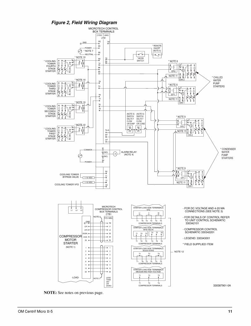
Figure 2, Field Wiring Diagram
80
CP2
CP1
H
O
A
C4
H
A
O
C3
H
A
O
79
78
77
74
73
54
CF
86
EF
86
C
25
1
2
11
11
12
22
1
2
6
11
12
22
NOTE 2
NOTE 2
(115V) (24V)
25
55
70
H
A
O
H
A
O
H
O
A C
H
O
A C
H
O
A C
C2
C1 T3-S
PE
L1
L2CP2
CP1
24
23(5A)
24(5)
23
3
4
3
4
76
75
PE
85
86
81
84
A82(NO)
83(NC)
POWER
EP2
EP1
L1 L2 L3
GND
T4 T5 T6T1 T2 T3
T4 T5 T6T1 T2 T3
T1 T2 T3
T3T1 T2
U V W
T4 T3 T5T1 T6 T2
T1 T2 T3
T4 T3 T5T1 T6 T2
GND
LESSTHAN30VOR24VAC
53
71
71
52
1-10 VDC
1-10 VDC
MICROTECH CONTROLBOX TERMINALS
* COOLINGTOWER
FOURTHSTAGE
STARTER
* COOLINGTOWER
THIRDSTAGE
STARTER
* COOLINGTOWER
SECONDHSTAGE
STARTER
* COOLINGTOWER
FIRSTSTAGE
STARTER
COOLING TOWERBYPASS VALVE
COOLING TOWER VFD
ALARM RELAY(NOTE 4)
MICROTECHCOMPRESSOR CONTROL
BOX TERMINALSCTB1
-LOAD-
COMPRESSORMOTOR
STARTER(NOTE 1)
115 VAC
STARTER LOAD SIDE TERMINBALSVFD
STARTER LOAD SIDE TERMINBALSWYE-DELTA
STARTER LOAD SIDE TERMINBALSSOLID STATE
STARTER LOAD SIDE TERMINBALSMEDIUM AND HIGH VOLTAGE
COMPRESSOR TERMINALS
COMPRESSOR TERMINALS
COMPRESSOR TERMINALS
COMPRESSOR TERMINALS
NOTE 12
- FOR DC VOLTAGE AND 4-20 MA CONNECTIONS (SEE NOTE 3)
- FOR DETAILS OF CONTROL REFER TO UNIT CONTROL SCHEMATIC 330342101
- COMPRESSOR CONTROL SCHEMATIC 330342201
- LEGEND: 330343001
* FIELD SUPPLIED ITEM
* NOTE 7
* NOTE 10
* NOTE 10
* NOTE 10
* NOTE 10
330387901-0A
COMMON
NEUTRAL
POWER
NOTE: See notes on previous page.
12 OM Centrif Micro ΙΙ-5
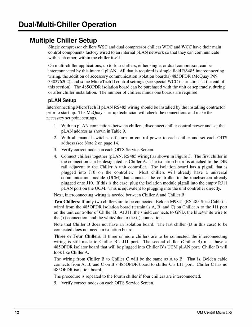
Dual/Multi-Chiller Operation
Multiple Chiller Setup Single compressor chillers WSC and dual compressor chillers WDC and WCC have their main
control components factory wired to an internal pLAN network so that they can communicate
with each other, within the chiller itself.
On multi-chiller applications, up to four chillers, either single, or dual compressor, can be
interconnected by this internal pLAN. All that is required is simple field RS485 interconnecting
wiring, the addition of accessory communication isolation board(s) 485OPDR (McQuay P/N
330276202), and some MicroTech II control settings (see special WCC instructions at the end of
this section). The 485OPDR isolation board can be purchased with the unit or separately, during
or after chiller installation. The number of chillers minus one boards are required.
pLAN Setup
Interconnecting MicroTech II pLAN RS485 wiring should be installed by the installing contractor
prior to start-up. The McQuay start-up technician will check the connections and make the
necessary set point settings.
1. With no pLAN connections between chillers, disconnect chiller control power and set the
pLAN address as shown in Table 9.
2. With all manual switches off, turn on control power to each chiller and set each OITS
address (see Note 2 on page 14).
3. Verify correct nodes on each OITS Service Screen.
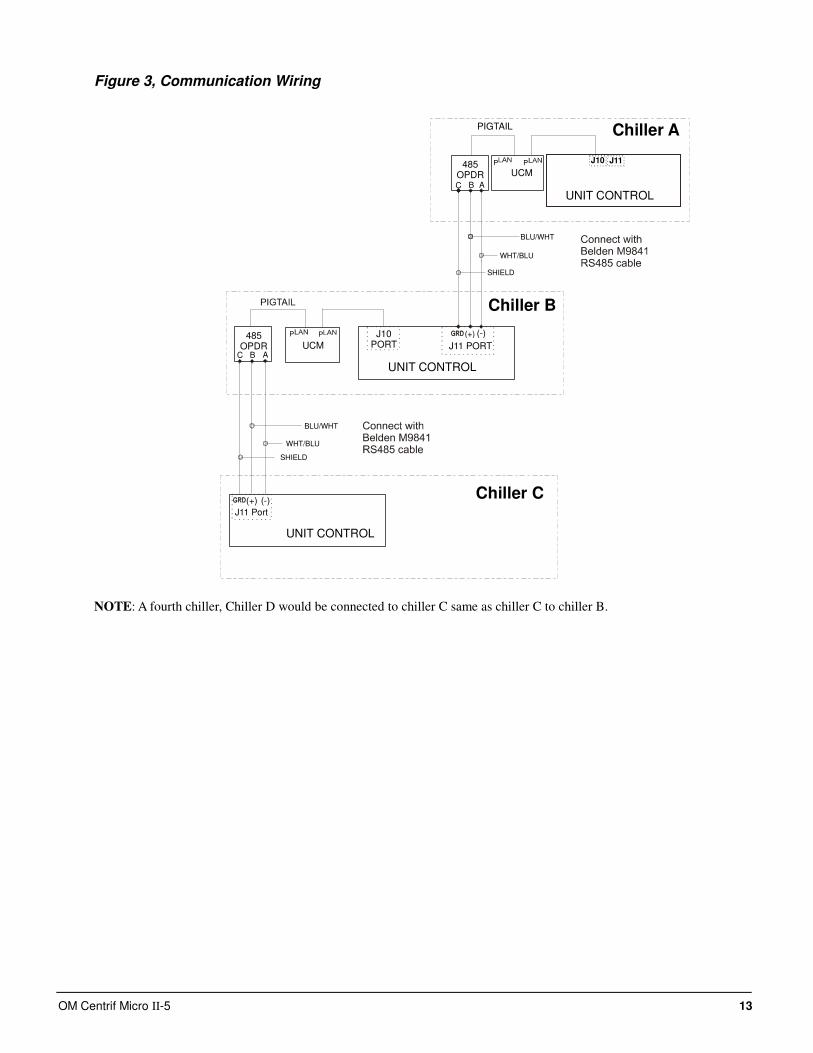
4. Connect chillers together (pLAN, RS485 wiring) as shown in Figure 3. The first chiller in
the connection can be designated as Chiller A. The isolation board is attached to the DIN
rail adjacent to the Chiller A unit controller. The isolation board has a pigtail that is
plugged into J10 on the controller. Most chillers will already have a universal
communication module (UCM) that connects the controller to the touchscreen already
plugged onto J10. If this is the case, plug the isolation module pigtail into the empty RJ11
pLAN port on the UCM. This is equivalent to plugging into the unit controller directly.
Next, interconnecting wiring is needed between Chiller A and Chiller B.
Two Chillers: If only two chillers are to be connected, Belden M9841 (RS 485 Spec Cable) is
wired from the 485OPDR isolation board (terminals A, B, and C) on Chiller A to the J11 port
on the unit controller of Chiller B. At J11, the shield connects to GND, the blue/white wire to
the (+) connection, and the white/blue to the (-) connection.
Note that Chiller B does not have an isolation board. The last chiller (B in this case) to be
connected does not need an isolation board.
Three or Four Chillers: If three or more chillers are to be connected, the interconnecting
wiring is still made to Chiller B’s J11 port. The second chiller (Chiller B) must have a
485OPDR isolator board that will be plugged into Chiller B’s UCM pLAN port. Chiller B will
look like Chiller A.
The wiring from Chiller B to Chiller C will be the same as A to B. That is, Belden cable
connects from A, B, and C on B’s 485OPDR board to chiller C’s L11 port. Chiller C has no
485OPDR isolation board.
The procedure is repeated to the fourth chiller if four chillers are interconnected.
5. Verify correct nodes on each OITS Service Screen.
OM Centrif Micro ΙΙ-5 13
Figure 3, Communication Wiring
Chiller APIGTAIL
485OPDRC AB
UCM
J10 J11
BLU/WHT
WHT/BLU
SHIELD
(+) (-)
UNIT CONTROL
J11 PORT
Chiller B
485OPDR
C
BLU/WHT
WHT/BLU
SHIELD
B AUCM
J10PORT
Chiller C(+) (-)
J11 Port
UNIT CONTROL
UNIT CONTROL
P P
P P
NOTE: A fourth chiller, Chiller D would be connected to chiller C same as chiller C to chiller B.
14 OM Centrif Micro ΙΙ-5
Table 9, pLAN address and DIP Switch Settings for Controllers Using pLAN.
Chiller
(1)
Comp 1
Controller
Comp 2
Controller
Unit
Controller
Reserved Operator
Interface (2)
Reserved
Dec. 1 2 5 6 7 8 A
Bin. 100000 010000 101000 011000 N/A 000100
Dec. 9 10 13 14 15 16 B
Bin. 100100 010100 101100 011100 N/A 000010
Dec. 17 18 21 22 23 24 C
Bin. 100010 010010 101010 011010 N/A 000110
Dec. 25 26 29 30 31 32 D
Bin. 100110 010110 101110 011110 N/A 000001
NOTES for pLAN multi-chiller communication setup:
1. Up to four single or dual compressors can be interconnected.
2. Operator Interface Touch Screen (OITS) setting is not a DIP switch setting. The OITS address is selected
by selecting the ‘service’ set screen. Then, with the Technician level password active, select the ‘pLAN
Comm’ button. Buttons A(7), B(15), C(23), D(31) will appear in the middle of the screen, then select the
letters for the OITS address for the chiller that it is on. Then close the screen. Note that A is the default
setting from the factory.
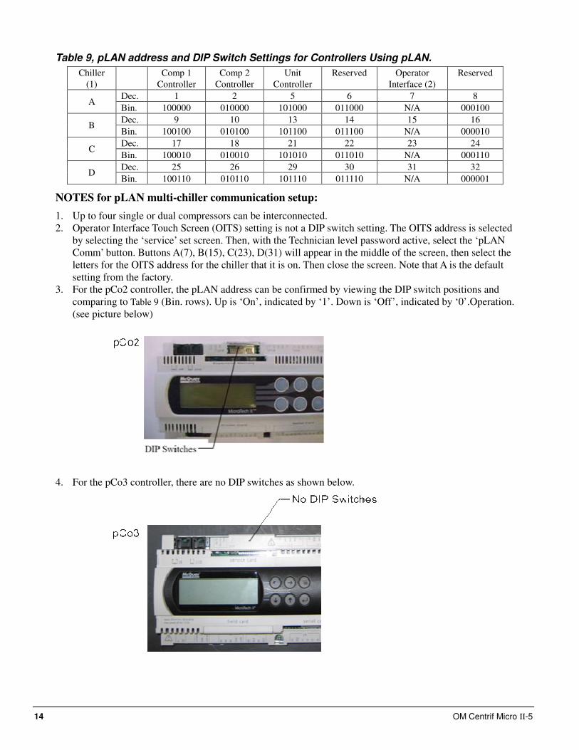
3. For the pCo2 controller, the pLAN address can be confirmed by viewing the DIP switch positions and
comparing to Table 9 (Bin. rows). Up is ‘On’, indicated by ‘1’. Down is ‘Off’, indicated by ‘0’.Operation.
(see picture below)
4. For the pCo3 controller, there are no DIP switches as shown below.
OM Centrif Micro ΙΙ-5 15
The pLAN address can only be confirmed as follows:
A) Disconnect pLAN (connectors J10 and J11) from all pCo2 and pCo3 controller(s).
B) Cycle power to the controller and then hold down both the Left Arrow (alarm) and the Up Arrow keys
simultaneously as the controller completes its Self-Test routine. The controller will then show you the
present pLAN address of the controller. Verify that the pLAN address matches the desired address from the
above table (Dec. rows). If the address needs to be changed, follow the instructions displayed on the pCo3
controller’s LCD display. Press enter when done.
C) Only after all controllers pLAN addresses have been set/confirmed can the pLAN network connectors be
re-connected.
MicroTech II Operator Interface Touch Screen (OITS) Settings
Settings for any type of linked multiple compressor operation must be made to the MicroTech II controller.
Settings on a dual compressor unit are made in the factory prior to shipment, but must be verified in the field
before startup. Settings for multiple chiller installations are set in the field on the Operator Interface Touch
Screen as follows:
Maximum Compressors ON – SETPOINTS - MODES screen, Selection #10 ‘= 2 for a dual, 4 for 2 duals, 3 for
three separate, single compressor chillers, etc. If all compressors in the system are to be available as normal
running compressors, then the value entered in #10 should equal the total number of compressors. If any
compressors are for standby and not operated in normal rotation, they should not be included in the compressor
count in Selection #10. The Max Comp ON setting can be made in only one touchscreen, the system will observe
the highest number set on all chillers-it is a global setting.
Sequence and Staging – SETPOINTS - MODES screen, Selection #12 & #14; #11 & #13. Sequence sets the
sequence in which compressors will start. Setting one or more compressors to “1” evokes the automatic lead/lag
feature and is the normal setting. The compressor with least starts will start first and the compressor with
maximum hours will stop first, and so on. Units with higher numbers will stage on in sequence.
The Modes setpoints will do several different types of operation (Normal, Efficiency, Standby, etc.) as described
in the operating manual.
The same Modes setting must be replicated on each chiller in the system.
Nominal Capacity – SETPOINTS - MOTOR screen, Selection #14. The setting is the compressor design tons.
Compressors on dual units are always of equal capacity.
Operating Sequence
For multiple-chiller, parallel operation, the MicroTech II controllers are tied together by a pLAN network and
stage and control compressor loading among the chillers. Each compressor, single or dual compressor chiller, will
stage on or off depending on the sequence number programmed into it. For example, if all are set to “1”, the
automatic lead/lag will be in effect.
When chiller #1 is fully loaded, the leaving chilled water temperature will rise slightly. When the Delta-T above
setpoint reaches the Staging Delta-T, the next chiller scheduled to start will receive a start signal and start its
pumps if they are set up to be controlled by the MicroTech controller. This procedure is repeated until all chillers
are running. The compressors will load-balance themselves.
If any of the chillers in the group are dual compressor, they will stage and load according to the staging
instructions.
WCC Settings Since the WCC is essentially two chillers combined into one counterflow, single pass, dual-circuit chiller, the
compressor on the downstream circuit (leaving chilled water) must always be designated as the Stage 1
compressor-first on, last off.
16 OM Centrif Micro ΙΙ-5
Ice Mode Operation
If available modes is set to ICE only the chiller will start (at start delta t) and run the Ice cycle described as
follows: The chiller will ignore softload and all Demand limits and rapidly load up to Maximum Amps setpoint.
The compressor(s) do not unload. If the chiller has dual compressors (WDC), the lead compressor will unload
approx. one minute after starting to allow the second compressor to start (at reduced lift pressure), then both
compressors will load to Max Amps. When both compressors have achieved the Ice LWT setpoint both
compressors will shutdown. The Evap pump will continue to run and if the Evap LWT climbs to the Start Delta
T the chiller will restart this process.
The following failsafe feature has been incorporated into the code. If one compressor reaches the Stop Delta
Temp (below the setpoint) before the other compressor has achieved the setpoint, both compressors will
shutdown.
If available modes is set to Cool/Ice with Ice mode operation selected, the chiller will run one ICE cycle and
shutdown (compressors and pumps) no automatic restart allowed. When the operator switches the chiller from
Ice to Cool mode the chiller will reset for operation. Changing modes can be done through the OITS, switches
or BAS interface, which ever is selected.
Some sort of migration freeze protection needs to be in place when the chiller terminates ice mode. This is
usually sensed by the liquid line sensor and forces a condenser pump to circulate to prevent freeze up of the
condenser.
Operator Interface Touch Screen
Navigation The home screen shown in VIEW screen on page 18 is usually left on (there is a screen-saver built in that is
reactivated by touching the screen anywhere). This VIEW screen contains the STOP and AUTO buttons used to
start and stop the unit when in Local control. Other groups of screens can be accessed from the Home screen by
pressing one of three buttons on the bottom of the screen; HISTORY, VIEW, SET.
• HISTORY will go to the last history screens viewed and can toggle between the two history screens.
• Trend History
• Alarm History
• VIEW will go to the next View screen and other sub-View screens used to look in detail at settings and the
operation of the chiller. Pressing View from any other screen will return to the Home View screen.
• SET will go to a series of screens used to set setpoints.
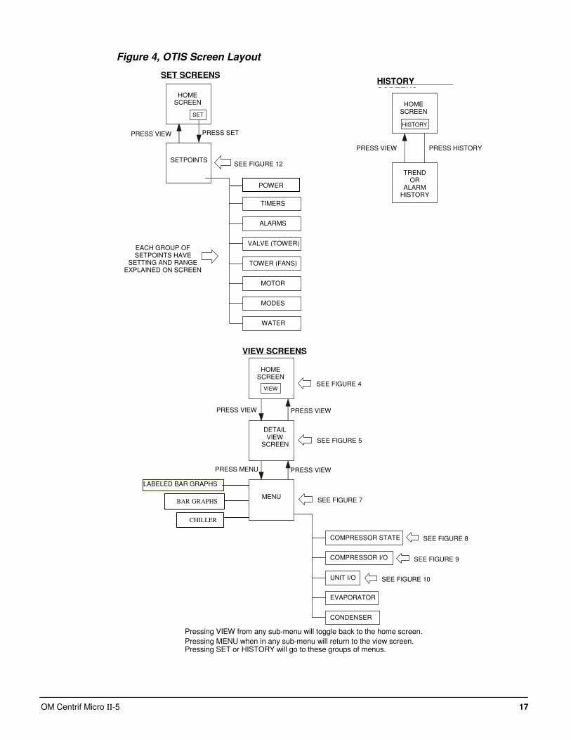
The figure on the following page illustrates the arrangement of the various screens available on the OITS. A few
minutes practice on an actual OITS should provide a comfortable level of confidence in navigating through the
screens.
OM Centrif Micro ΙΙ-5 17
Figure 4, OTIS Screen Layout
HOMESCREEN
SETPOINTS
HOMESCREEN
TRENDOR
ALARMHISTORY
TIMERS
ALARMS
VALVE (TOWER)
TOWER (FANS)
MOTOR
MODES
WATER
SET
PRESS SETPRESS VIEW
SEE FIGURE 12
EACH GROUP OFSETPOINTS HAVE
SETTING AND RANGEEXPLAINED ON SCREEN
HISTORY
PRESS HISTORYPRESS VIEW
SET SCREENS
HOMESCREEN
DETAILVIEW
SCREEN
COMPRESSOR STATE
COMPRESSOR I/O
UNIT I/O
EVAPORATOR
CONDENSER
VIEW
PRESS VIEWPRESS VIEW
SEE FIGURE 5
SEE FIGURE 8
SEE FIGURE 9
SEE FIGURE 10
Pressing VIEW from any sub-menu will toggle back to the home screen.
Pressing MENU when in any sub-menu will return to the view screen.Pressing SET or HISTORY will go to these groups of menus.
VIEW SCREENS
HISTORYSCREENS
SEE FIGURE 4
PRESS VIEWPRESS MENU
MENU
LABELED BAR GRAPHS
SEE FIGURE 7BAR GRAPHS
CHILLER
POWER
18 OM Centrif Micro ΙΙ-5
Screen Descriptions
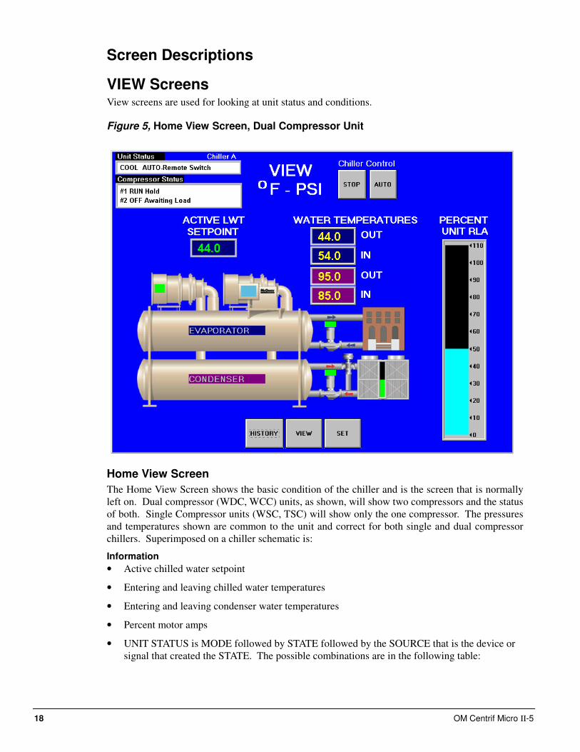
VIEW Screens View screens are used for looking at unit status and conditions.
Figure 5, Home View Screen, Dual Compressor Unit
Home View Screen
The Home View Screen shows the basic condition of the chiller and is the screen that is normally
left on. Dual compressor (WDC, WCC) units, as shown, will show two compressors and the status
of both. Single Compressor units (WSC, TSC) will show only the one compressor. The pressures
and temperatures shown are common to the unit and correct for both single and dual compressor
chillers. Superimposed on a chiller schematic is:
Information
• Active chilled water setpoint
• Entering and leaving chilled water temperatures
• Entering and leaving condenser water temperatures
• Percent motor amps
• UNIT STATUS is MODE followed by STATE followed by the SOURCE that is the device or
signal that created the STATE. The possible combinations are in the following table:
OM Centrif Micro ΙΙ-5 19
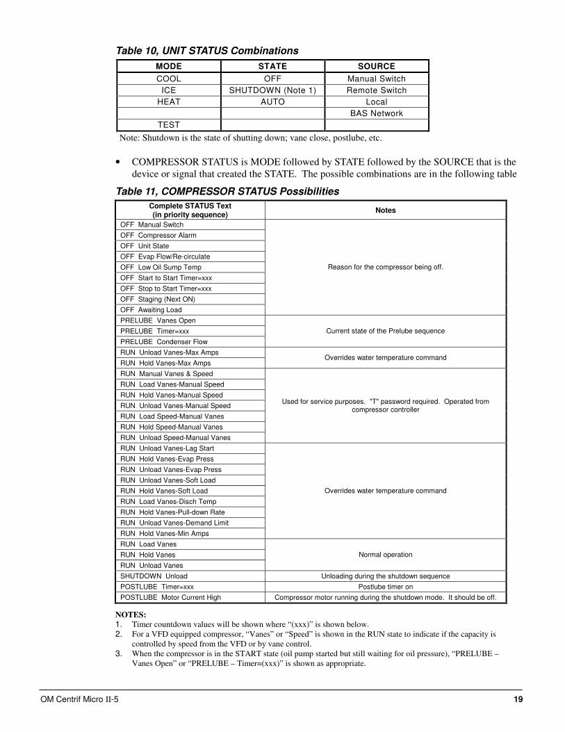
Table 10, UNIT STATUS Combinations
MODE STATE SOURCE
COOL OFF Manual Switch
ICE SHUTDOWN (Note 1) Remote Switch
HEAT AUTO Local
BAS Network
TEST
Note: Shutdown is the state of shutting down; vane close, postlube, etc.
• COMPRESSOR STATUS is MODE followed by STATE followed by the SOURCE that is the
device or signal that created the STATE. The possible combinations are in the following table
Table 11, COMPRESSOR STATUS Possibilities
Complete STATUS Text (in priority sequence)
Notes
OFF Manual Switch
OFF Compressor Alarm
OFF Unit State
OFF Evap Flow/Re-circulate
OFF Low Oil Sump Temp
OFF Start to Start Timer=xxx
OFF Stop to Start Timer=xxx
OFF Staging (Next ON)
OFF Awaiting Load
Reason for the compressor being off.
PRELUBE Vanes Open
PRELUBE Timer=xxx
PRELUBE Condenser Flow
Current state of the Prelube sequence
RUN Unload Vanes-Max Amps
RUN Hold Vanes-Max Amps Overrides water temperature command
RUN Manual Vanes & Speed
RUN Load Vanes-Manual Speed
RUN Hold Vanes-Manual Speed
RUN Unload Vanes-Manual Speed
RUN Load Speed-Manual Vanes
RUN Hold Speed-Manual Vanes
RUN Unload Speed-Manual Vanes
Used for service purposes. "T" password required. Operated from compressor controller
RUN Unload Vanes-Lag Start
RUN Hold Vanes-Evap Press
RUN Unload Vanes-Evap Press
RUN Unload Vanes-Soft Load
RUN Hold Vanes-Soft Load
RUN Load Vanes-Disch Temp
RUN Hold Vanes-Pull-down Rate
RUN Unload Vanes-Demand Limit
RUN Hold Vanes-Min Amps
Overrides water temperature command
RUN Load Vanes
RUN Hold Vanes
RUN Unload Vanes
Normal operation
SHUTDOWN Unload Unloading during the shutdown sequence
POSTLUBE Timer=xxx Postlube timer on
POSTLUBE Motor Current High Compressor motor running during the shutdown mode. It should be off.
NOTES:
1. Timer countdown values will be shown where “(xxx)” is shown below. 2. For a VFD equipped compressor, “Vanes” or “Speed” is shown in the RUN state to indicate if the capacity is
controlled by speed from the VFD or by vane control. 3. When the compressor is in the START state (oil pump started but still waiting for oil pressure), “PRELUBE –
Vanes Open” or “PRELUBE – Timer=(xxx)” is shown as appropriate.
20 OM Centrif Micro ΙΙ-5
Action Buttons for:
• AUTO and STOP buttons, normal start (AUTO) and STOP button activates the normal start
and shutdown sequence. These buttons are only active when the control is in the "Local
Control" mode. This eliminates the possibility of inadvertently shutting off the unit locally
when it is under control of a remote signal such as a BAS.
• HISTORY, toggles between the Trend History screen and the Alarm History screen.
• SET, toggles between the Set Points screen that are used for changing setpoints and the
Service screen.
Returning
Pressing the VIEW button from any screen will return to the HOME VIEW screen.
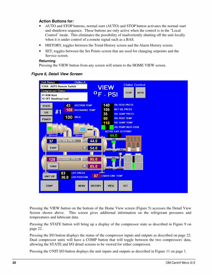
Figure 6, Detail View Screen
Pressing the VIEW button on the bottom of the Home View screen (Figure 5) accesses the Detail View
Screen shown above. This screen gives additional information on the refrigerant pressures and
temperatures and lubricant data.
Pressing the STATE button will bring up a display of the compressor state as described in Figure 9 on
page 22.
Pressing the I/O button displays the status of the compressor inputs and outputs as described on page 22.
Dual compressor units will have a COMP button that will toggle between the two compressors' data,
allowing the STATE and I/O detail screens to be viewed for either compressor.
Pressing the UNIT I/O button displays the unit inputs and outputs as described in Figure 11 on page 1.
OM Centrif Micro ΙΙ-5 21
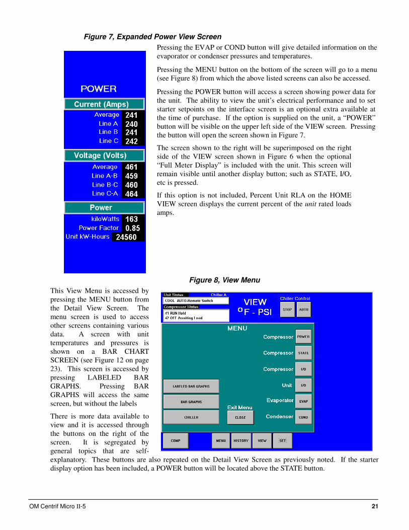
Figure 7, Expanded Power View Screen
Pressing the EVAP or COND button will give detailed information on the
evaporator or condenser pressures and temperatures.
Pressing the MENU button on the bottom of the screen will go to a menu
(see Figure 8) from which the above listed screens can also be accessed.
Pressing the POWER button will access a screen showing power data for
the unit. The ability to view the unit’s electrical performance and to set
starter setpoints on the interface screen is an optional extra available at
the time of purchase. If the option is supplied on the unit, a “POWER”
button will be visible on the upper left side of the VIEW screen. Pressing
the button will open the screen shown in Figure 7.
The screen shown to the right will be superimposed on the right
side of the VIEW screen shown in Figure 6 when the optional
“Full Meter Display” is included with the unit. This screen will
remain visible until another display button; such as STATE, I/O,
etc is pressed.
If this option is not included, Percent Unit RLA on the HOME
VIEW screen displays the current percent of the unit rated loads
amps.
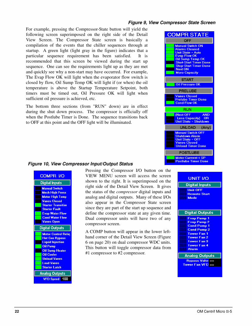
Figure 8, View Menu
This View Menu is accessed by
pressing the MENU button from
the Detail View Screen. The
menu screen is used to access
other screens containing various
data. A screen with unit
temperatures and pressures is
shown on a BAR CHART
SCREEN (see Figure 12 on page
23). This screen is accessed by
pressing LABELED BAR
GRAPHS. Pressing BAR
GRAPHS will access the same
screen, but without the labels
There is more data available to
view and it is accessed through
the buttons on the right of the
screen. It is segregated by
general topics that are self-
explanatory. These buttons are also repeated on the Detail View Screen as previously noted. If the starter
display option has been included, a POWER button will be located above the STATE button.
22 OM Centrif Micro ΙΙ-5
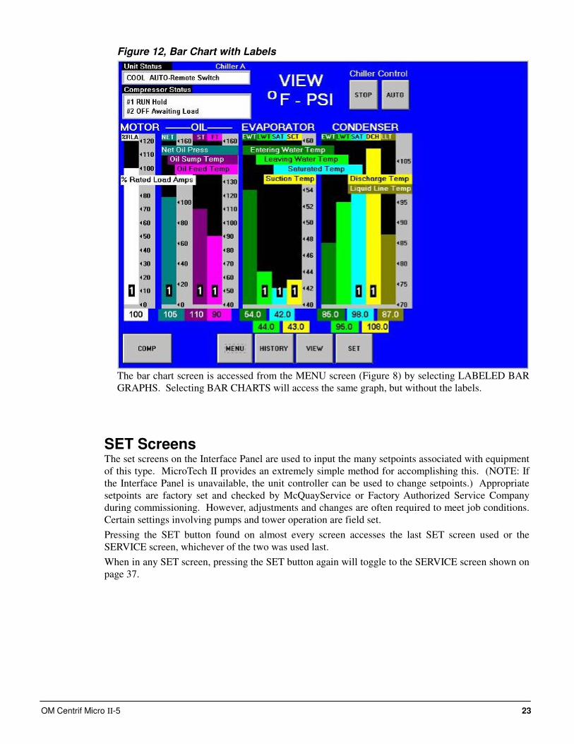
Figure 9, View Compressor State Screen
For example, pressing the Compressor-State button will yield the
following screen superimposed on the right side of the Detail
View Screen. The Compressor State screen is basically a
compilation of the events that the chiller sequences through at
startup. A green light (light gray in the figure) indicates that a
particular sequence requirement has been satisfied. It is
recommended that this screen be viewed during the start up
sequence. One can see the requirements light up as they are met
and quickly see why a non-start may have occurred. For example,
The Evap Flow OK will light when the evaporator flow switch is
closed by flow, Oil Sump Temp OK will light if (or when) the oil
temperature is above the Startup Temperature Setpoint, both
timers must be timed out, Oil Pressure OK will light when
sufficient oil pressure is achieved, etc.
The bottom three sections (from "RUN" down) are in effect
during the shut down process. The compressor is officially off
when the Postlube Timer is Done. The sequence transitions back
to OFF at this point and the OFF light will be illuminated.
Figure 10, View Compressor Input/Output Status
Pressing the Compressor I/O button on the
VIEW MENU screen will access the screen
shown to the right. It is superimposed on the
right side of the Detail View Screen. It gives
the status of the compressor digital inputs and
analog and digital outputs. Many of these I/Os
also appear in the Compressor State screen
since they are part of the start up sequence and
define the compressor state at any given time.
Dual compressor units will have two of any
compressor screen.
A COMP button will appear in the lower left-
hand corner of the Detail View Screen (Figure
6 on page 20) on dual compressor WDC units.
This button will toggle compressor data from
#1 compressor to #2 compressor.
OM Centrif Micro ΙΙ-5 23
Figure 12, Bar Chart with Labels
The bar chart screen is accessed from the MENU screen (Figure 8) by selecting LABELED BAR
GRAPHS. Selecting BAR CHARTS will access the same graph, but without the labels.
SET Screens The set screens on the Interface Panel are used to input the many setpoints associated with equipment
of this type. MicroTech II provides an extremely simple method for accomplishing this. (NOTE: If
the Interface Panel is unavailable, the unit controller can be used to change setpoints.) Appropriate
setpoints are factory set and checked by McQuayService or Factory Authorized Service Company
during commissioning. However, adjustments and changes are often required to meet job conditions.
Certain settings involving pumps and tower operation are field set.
Pressing the SET button found on almost every screen accesses the last SET screen used or the
SERVICE screen, whichever of the two was used last.
When in any SET screen, pressing the SET button again will toggle to the SERVICE screen shown on
page 37.
24 OM Centrif Micro ΙΙ-5
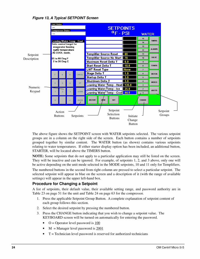
Figure 13, A Typical SETPOINT Screen
The above figure shows the SETPOINT screen with WATER setpoints selected. The various setpoint
groups are in a column on the right side of the screen. Each button contains a number of setpoints
grouped together by similar content. The WATER button (as shown) contains various setpoints
relating to water temperatures. If either starter display option has been included, an additional button,
STARTER, will be located above the TIMERS button.
NOTE: Some setpoints that do not apply to a particular application may still be listed on the screen.
They will be inactive and can be ignored. For example, of setpoints 1, 2, and 3 above, only one will
be active depending on the unit mode selected in the MODE setpoints, 10 and 11 only for Templifiers.
The numbered buttons in the second from right column are pressed to select a particular setpoint. The
selected setpoint will appear in blue on the screen and a description of it (with the range of available
settings) will appear in the upper left-hand box.
Procedure for Changing a Setpoint
A list of setpoints, their default value, their available setting range, and password authority are in
Table 23 on page 51 for the unit and Table 24 on page 63 for the compressor.
1. Press the applicable Setpoint Group Button. A complete explanation of setpoint content of
each group follows this section.
2. Select the desired setpoint by pressing the numbered button.
3. Press the CHANGE button indicating that you wish to change a setpoint value. The
KEYBOARD screen will be turned on automatically for entering the password.
• O = Operator level password is 100
• M = Manager level password is 2001
• T = Technician level password is reserved for authorized technicians
Setpoint
Groups
Setpoint
Selection
Buttons Initiate
Change
Button
Numeric
Keypad
Action
Buttons
Setpoint
Description
Setpoints
OM Centrif Micro ΙΙ-5 25
4. Press the appropriate numbers in the numeric keyboard to enter the password. There is a small
delay between pressing the keypad and recording the entry. Be sure that an asterisk appears in
the window before pressing the next number. Press ENTER to return to the SETPOINT
screen. The password will remain open for 15 minute after initiation and does not need to be
re-entered during this period.
5. Press CHANGE again. The right side of the screen will turn blue (inactive).
6. The numeric keypad and action buttons in the lower left-hand corner of the screen will be
activated (the background will turn green). Setpoints with numeric values can be changed in
two ways:
• Select the desired value by pressing the numbered buttons. Press ENTER to enter the
value or CANCEL to cancel the transaction.
• Press the UP or DOWN button to increase or decrease the value displayed. Press ENTER
to enter the value or CANCEL to cancel the transaction.
Some setpoints are text rather than numeric values. For example, LWT Reset Type can be
"None" or "4-20 ma". The selection can be made by toggling between choices using the
UP or Down button. If dashed lines appear in the setpoint window, it indicates that you
have toggled too far and need to reverse direction. Press ENTER to enter the choice or
CANCEL to cancel the transaction.
Once CHANGE is selected, the CANCEL or ENTER buttons must be pressed before
another setpoint can be selected.
7. Additional setpoints can be changed by selecting another setpoint on the screen or by selecting
an entirely new group of setpoints.
Explanation of Setpoints Each of the seven setpoint group of screens are detailed in the following section. In many cases
the setpoint content is obvious and no explanation is included.
1. TIMERS, for setting timers such as start-to-start, prelube, postlube, etc.
2. ALARMS, for setting the limit and shutdown alarms.
3. VALVE, sets the parameters for operation of an optional field installed tower bypass valve.
4. TOWER, selects the method of controlling the cooling tower and sets the parameters for fan
staging/VFD.
5. MOTOR, selects motor related setpoints such as amp limits, VFD settings, etc. Also has
maximum and minimum rate of change of chilled water temperature.
6. MODES, selects various modes of operation such as control source, multiple compressor
staging, pump staging, BAS protocol, etc.
7. WATER, leaving water temperature setpoint, start and stop delta-T, resets, etc.
26 OM Centrif Micro ΙΙ-5
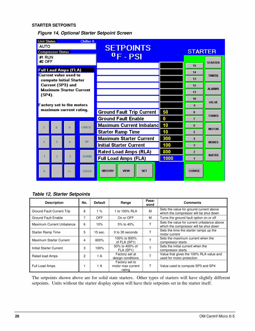
STARTER SETPOINTS
Figure 14, Optional Starter Setpoint Screen
Table 12, Starter Setpoints
Description No. Default Range Pass- word
Comments
Ground Fault Current Trip 8 1 % 1 to 100% RLA M Sets the value for ground current above which the compressor will be shut down
Ground Fault Enable 7 OFF On or OFF M Turns the ground fault option on or off
Maximum Current Unbalance 6 10% 5% to 40% T Sets the value for current unbalance above which the compressor will be shut down
Starter Ramp Time 5 15 sec. 0 to 30 seconds T Sets the time the starter ramps up the motor current
Maximum Starter Current 4 600% 100% to 800% of FLA (SP1)
T Sets the maximum current when the compressor starts
Initial Starter Current 3 100% 50% to 400% of
FLA (SP1) T
Sets the initial current when the compressor starts
Rated load Amps 2 1 A Factory set at
design conditions T
Value that gives the 100% RLA value and used for motor protection
Full Load Amps 1 1 A Factory set to
motor max current rating
T Value used to compute SP3 and SP4
The setpoints shown above are for solid state starters. Other types of starters will have slightly different
setpoints. Units without the starter display option will have their setpoints set in the starter itself.
OM Centrif Micro ΙΙ-5 27
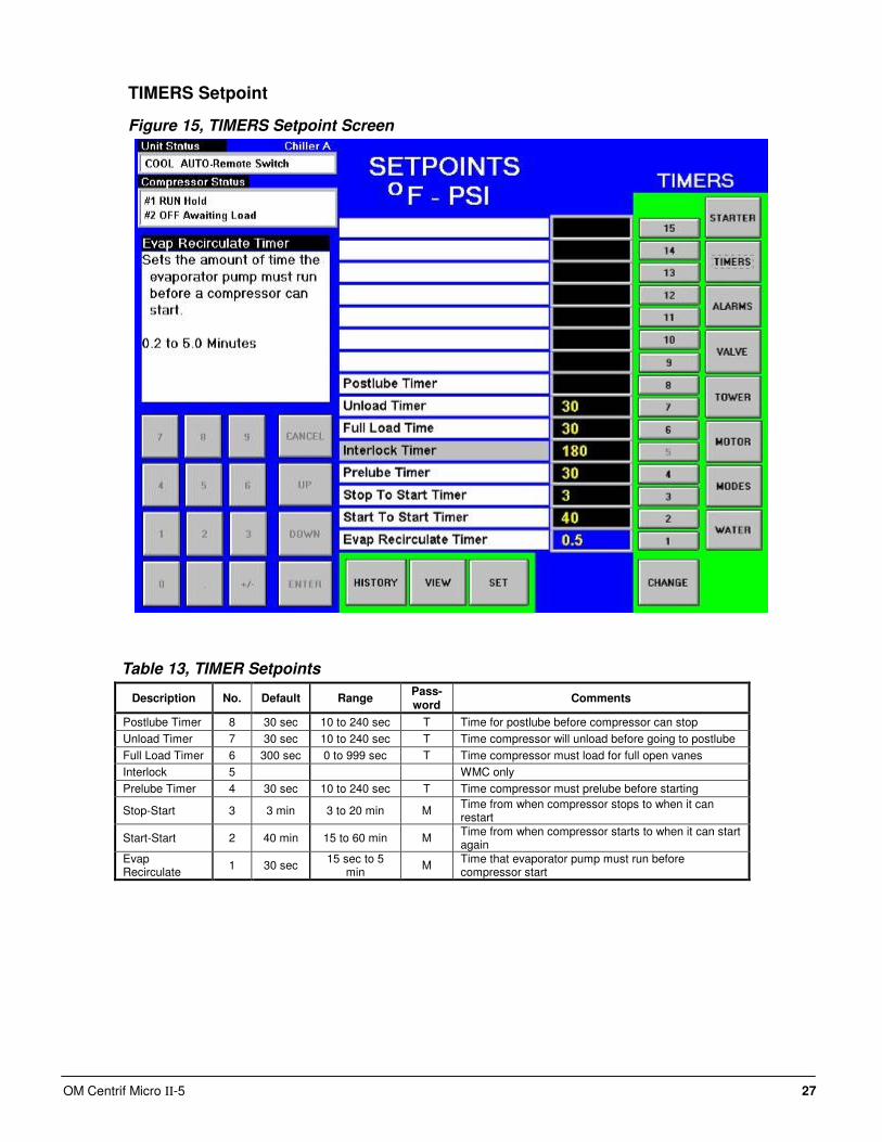
TIMERS Setpoint
Figure 15, TIMERS Setpoint Screen
Table 13, TIMER Setpoints
Description No. Default Range Pass-word
Comments
Postlube Timer 8 30 sec 10 to 240 sec T Time for postlube before compressor can stop
Unload Timer 7 30 sec 10 to 240 sec T Time compressor will unload before going to postlube
Full Load Timer 6 300 sec 0 to 999 sec T Time compressor must load for full open vanes
Interlock 5 WMC only
Prelube Timer 4 30 sec 10 to 240 sec T Time compressor must prelube before starting
Stop-Start 3 3 min 3 to 20 min M Time from when compressor stops to when it can restart
Start-Start 2 40 min 15 to 60 min M Time from when compressor starts to when it can start again
Evap Recirculate
1 30 sec 15 sec to 5
min M
Time that evaporator pump must run before compressor start
28 OM Centrif Micro ΙΙ-5
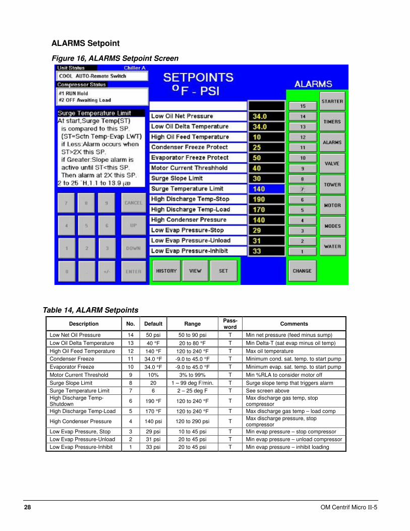
ALARMS Setpoint
Figure 16, ALARMS Setpoint Screen
Table 14, ALARM Setpoints
Description No. Default Range Pass-word
Comments
Low Net Oil Pressure 14 50 psi 50 to 90 psi T Min net pressure (feed minus sump)
Low Oil Delta Temperature 13 40 °F 20 to 80 °F T Min Delta-T (sat evap minus oil temp)
High Oil Feed Temperature 12 140 °F 120 to 240 °F T Max oil temperature
Condenser Freeze 11 34.0 °F -9.0 to 45.0 °F T Minimum cond. sat. temp. to start pump
Evaporator Freeze 10 34.0 °F -9.0 to 45.0 °F T Minimum evap. sat. temp. to start pump
Motor Current Threshold 9 10% 3% to 99% T Min %RLA to consider motor off
Surge Slope Limit 8 20 1 – 99 deg F/min. T Surge slope temp that triggers alarm
Surge Temperature Limit 7 6 2 – 25 deg F T See screen above
High Discharge Temp-Shutdown
6 190 °F 120 to 240 °F T Max discharge gas temp, stop compressor
High Discharge Temp-Load 5 170 °F 120 to 240 °F T Max discharge gas temp – load comp
High Condenser Pressure 4 140 psi 120 to 290 psi T Max discharge pressure, stop compressor
Low Evap Pressure, Stop 3 29 psi 10 to 45 psi T Min evap pressure – stop compressor
Low Evap Pressure-Unload 2 31 psi 20 to 45 psi T Min evap pressure – unload compressor
Low Evap Pressure-Inhibit 1 33 psi 20 to 45 psi T Min evap pressure – inhibit loading
OM Centrif Micro ΙΙ-5 29
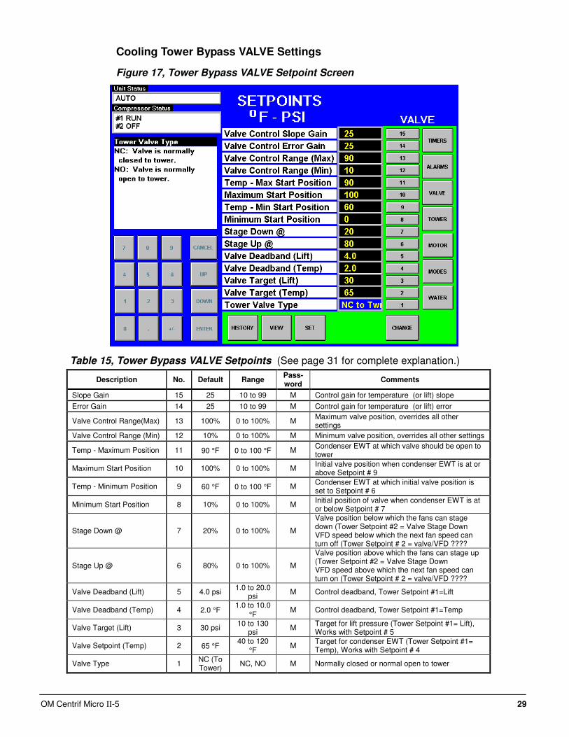
Cooling Tower Bypass VALVE Settings
Figure 17, Tower Bypass VALVE Setpoint Screen
Table 15, Tower Bypass VALVE Setpoints (See page 31 for complete explanation.)
Description No. Default Range Pass-word
Comments
Slope Gain 15 25 10 to 99 M Control gain for temperature (or lift) slope
Error Gain 14 25 10 to 99 M Control gain for temperature (or lift) error
Valve Control Range(Max) 13 100% 0 to 100% M Maximum valve position, overrides all other settings
Valve Control Range (Min) 12 10% 0 to 100% M Minimum valve position, overrides all other settings
Temp - Maximum Position 11 90 °F 0 to 100 °F M Condenser EWT at which valve should be open to tower
Maximum Start Position 10 100% 0 to 100% M Initial valve position when condenser EWT is at or above Setpoint # 9
Temp - Minimum Position 9 60 °F 0 to 100 °F M Condenser EWT at which initial valve position is set to Setpoint # 6
Minimum Start Position 8 10% 0 to 100% M Initial position of valve when condenser EWT is at or below Setpoint # 7
Stage Down @ 7 20% 0 to 100% M
Valve position below which the fans can stage down (Tower Setpoint #2 = Valve Stage Down VFD speed below which the next fan speed can turn off (Tower Setpoint # 2 = valve/VFD ????
Stage Up @ 6 80% 0 to 100% M
Valve position above which the fans can stage up (Tower Setpoint #2 = Valve Stage Down VFD speed above which the next fan speed can turn on (Tower Setpoint # 2 = valve/VFD ????
Valve Deadband (Lift) 5 4.0 psi 1.0 to 20.0
psi M Control deadband, Tower Setpoint #1=Lift
Valve Deadband (Temp) 4 2.0 °F 1.0 to 10.0
°F M Control deadband, Tower Setpoint #1=Temp
Valve Target (Lift) 3 30 psi 10 to 130
psi M
Target for lift pressure (Tower Setpoint #1= Lift), Works with Setpoint # 5
Valve Setpoint (Temp) 2 65 °F 40 to 120
°F M
Target for condenser EWT (Tower Setpoint #1= Temp), Works with Setpoint # 4
Valve Type 1 NC (To Tower)
NC, NO M Normally closed or normal open to tower
30 OM Centrif Micro ΙΙ-5
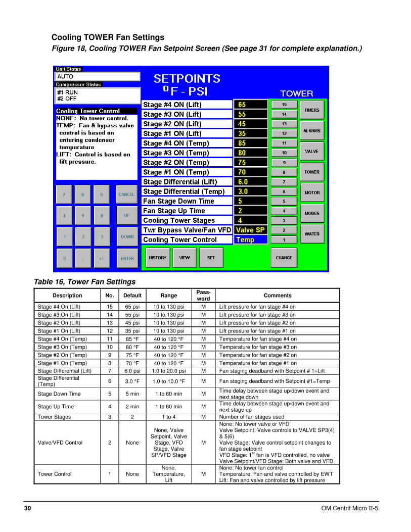
Cooling TOWER Fan Settings
Figure 18, Cooling TOWER Fan Setpoint Screen (See page 31 for complete explanation.)
Table 16, Tower Fan Settings
Description No. Default Range Pass-word
Comments
Stage #4 On (Lift) 15 65 psi 10 to 130 psi M Lift pressure for fan stage #4 on
Stage #3 On (Lift) 14 55 psi 10 to 130 psi M Lift pressure for fan stage #3 on
Stage #2 On (Lift) 13 45 psi 10 to 130 psi M Lift pressure for fan stage #2 on
Stage #1 On (Lift) 12 35 psi 10 to 130 psi M Lift pressure for fan stage #1 on
Stage #4 On (Temp) 11 85 °F 40 to 120 °F M Temperature for fan stage #4 on
Stage #3 On (Temp) 10 80 °F 40 to 120 °F M Temperature for fan stage #3 on
Stage #2 On (Temp) 9 75 °F 40 to 120 °F M Temperature for fan stage #2 on
Stage #1 On (Temp) 8 70 °F 40 to 120 °F M Temperature for fan stage #1 on
Stage Differential (Lift) 7 6.0 psi 1.0 to 20.0 psi M Fan staging deadband with Setpoint # 1=Lift
Stage Differential (Temp)
6 3.0 °F 1.0 to 10.0 °F M Fan staging deadband with Setpoint #1=Temp
Stage Down Time 5 5 min 1 to 60 min M Time delay between stage up/down event and next stage down
Stage Up Time 4 2 min 1 to 60 min M Time delay between stage up/down event and next stage up
Tower Stages 3 2 1 to 4 M Number of fan stages used
Valve/VFD Control 2 None
None, Valve Setpoint, Valve
Stage, VFD Stage, Valve
SP/VFD Stage
M
None: No tower valve or VFD Valve Setpoint: Valve controls to VALVE SP3(4) & 5(6) Valve Stage: Valve control setpoint changes to fan stage setpoint VFD Stage: 1
st fan is VFD controlled, no valve
Valve Setpoint/VFD Stage: Both valve and VFD
Tower Control 1 None None,
Temperature, Lift
M None: No tower fan control Temperature: Fan and valve controlled by EWT Lift: Fan and valve controlled by lift pressure
OM Centrif Micro ΙΙ-5 31
Explaination of Tower Control Settings
MicroTech II control can control cooling tower fan stages, a tower bypass valve, and/or a tower
fan VFD if the chiller has a dedicated cooling tower.
The Tower Bypass Valve position will always control the Tower Fan Staging if Valve Setpoint,
Stage Setpoint is selected. Fan staging is determined by Min & Max Tower Valve Position.
There are five possible tower control strategies as noted below and explained in detail later in this
section. They are selected from SETPOINT TOWER SP2.
1. NONE, Tower fan staging only. In this mode the tower fan staging (up to 4 stages) is
controlled by either the condenser Entering Water Temperature (EWT) or LIFT pressure
(difference between the condenser and evaporator pressures). Tower bypass or fan speed are
not controlled.
2. VALVE SP, Tower staging with low-limit controlled bypass valve. In this mode the tower fans
are controlled as in #1 plus a tower bypass valve is controlled to provide a minimum
condenser EWT. There is no interconnection between the fan control and the valve control.
3. VALVE STAGE, Tower staging with stage controlled bypass valve. In this mode the bypass
valve controls between fan stages to smooth the control and reduce fan cycling
4. VFD STAGE. In this mode a VFD controls the first fan. Up to 3 more fans are staged on and
off and there is no bypass valve.
5. VALVE/VFD, Tower fan control with VFD plus bypass valve control.
Tower Fan Staging Only (NONE)
The following settings are used for the Tower Fan Staging Only mode, (SP= setpoint)
1) TOWER SETPOINT Screen
i) SP1. Select TEMP if control is based on condenser EWT or LIFT if based on
compressor lift expressed in psi.
ii) SP2. Select NONE for no bypass valve or fan VFD control.
iii) SP3. Select one to four fan outputs depending on the number of fan stages to be used.
More than one fan can be used per stage through the use of relays.
iv) SP4. Select STAGE UP TIME from 1 to 60 minutes. The default value of 2 minutes is
probably a good starting point. The value may need to be adjusted later depending on
actual system operation.
v) SP5. Select STAGE DOWN TIME from 1 to 60 minutes. The default value of 5 minutes
is probably a good starting point. The value may need to be adjusted later depending on
actual system operation.
2) If TEMP is selected in SP1, use
i) SP6. Select STAGE DIFFERENTIAL in degrees F, start with default of 3 degrees F.
ii) SP8-11. Set the STAGE ON temperatures consistent with the temperature range over
which the condenser EWT is desired to operate. The default values of 70°F, 75°F, 80°F
and 85°F are a good place to start in climates with moderate wet bulb temperatures. The
number of STAGE ON setpoints used must be the same as SP3.
3) If LIFT is selected in SP1, use
i) SP7. Select STAGE DIFFERENTIAL in PSI. Start with default of 6 PSI.
ii) SP12-15. Start with default setpoints. The number of STAGE ON setpoints used must be
the same as SP3.
See Figure 2, Field Wiring Diagram on page 11 for fan staging field wiring connection points.
32 OM Centrif Micro ΙΙ-5
Tower Fan Staging With Bypass Valve Controlling Minimum EWT (VALVE SP) 1) TOWER SETPOINT Screen
a) SP1. Select TEMP if control is based on condenser EWT or LIFT if based on compressor
lift expressed in psi.
b) SP2. Select Valve SP for control of bypass valve based on temperature or lift.
c) SP3. Select one to four fan outputs depending on the number of fan stages to be used.
More than one fan can be used per stage through the use of relays.
d) SP4. Select STAGE UP TIME from 1 to 60 minutes. The default value of 2 minutes is
probably a good starting point. The value may need to be adjusted later depending on
actual system operation.
e) SP5. Select STAGE DOWN TIME from 1 to 60 minutes. The default value of 5 minutes
is probably a good starting point. The value may need to be adjusted later depending on
actual system operation.
f) If TEMP is selected in SP1, use
i) SP6. Select STAGE DIFFERENTIAL in degrees F, start with default of 3 degrees F.
ii) SP8-11. Set the STAGE ON temperatures consistent with the temperature range over
which the condenser EWT is desired to operate. The default values of 70°F, 75°F,
80°F and 85°F are a good place to start in climates with moderate wet bulb
temperatures. The number of STAGE ON setpoints used must be the same as SP3.
g) If LIFT is selected in SP1, use
i) SP7. Select STAGE DIFFERENTIAL in PSI. Start with default of 6 PSI.
ii) SP12-15. Start with default setpoints. The number of STAGE ON setpoints used
must be the same as SP3.
2) VALVE SETPOINT Screen
a) SP1, Select NC or NO depending if valve is closed to tower with no control power or open
to tower with no control power.
b) If TEMP was selected for fan control above, use
i) SP2, Set the VALVE TARGET (setpoint), usually 5 degrees below the minimum fan
stage setpoint established in TOWER SP11. This keeps full flow through the tower
until the last fan is staged off.
ii) SP4, Set VALVE DEADBAND, the default of 2 degrees F is a good place to start.
iii) SP8, Set MINIMUM VALVE POSITION when EWT is at or below SP9. Default is
0%.
iv) SP9, Set the EWT at which the valve position will be at (SP8). Default is 60°F.
v) SP8, Set MINIMUM VALVE POSITION when EWT is at or below SP9. Default is
0%.
vi) SP9, Set the EWT at which the valve position is set to allow the fans to stage up
(SP8). Default is 60°F.
vii) SP10, Set the initial valve position when EWT is at or above SP11. Default is 100%.
SP11, Set the EWT at which initial valve position is set to SP8. Default is 90°F.
viii) SP12, Set the minimum position to which the valve can go. Default is 10%.
ix) SP13, Set the maximum position to which the valve can go. Default is 100%.
x) SP14, Set the control gain for error. Default is 25.
xi) SP15, Set the control gain for slope. Default is 25.
OM Centrif Micro ΙΙ-5 33
NOTE: Setpoints 14 and 15 are site specific dealing with system fluid mass, component
size and other factors affecting the reaction of the system to control inputs. These
setpoints should be set by personnel experienced with setting up this type of control.
c) If LIFT was selected for fan control, use
i) SP3, Set the VALVE TARGET (setpoint), usually 30 psi below the minimum fan
stage setpoint established in TOWER SP12. This keeps full flow through the tower
until the last fan is staged off.
ii) SP5, Set VALVE DEADBAND, the default of 6 psi is a good place to start.
iii) SP8, Set MINIMUM VALVE POSITION when EWT is at or below SP9. Default is
0%.
iv) SP9, Set the EWT at which the valve position will be at (SP8). Default is 60°F.
v) SP12, Set the minimum position to which the valve can go. Default is 10%.
vi) SP13, Set the maximum position to which the valve can go. Default is 100%.
vii) SP14, Set the control gain for error. Default is 25.
viii) SP15, Set the control gain for slope. Default is 25.
NOTE: Setpoints 14 and 15 are site specific dealing with system fluid mass, component
size and other factors affecting the reaction of the system to control inputs. These
setpoints should be set by personnel experienced with setting up this type of control.
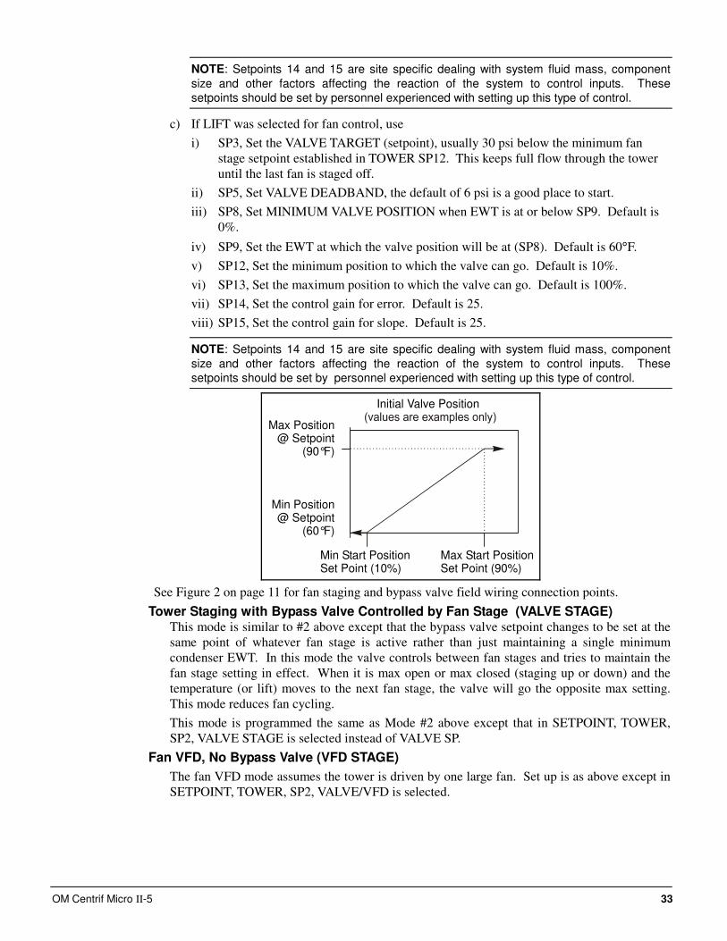
Initial Valve Position
Max Start PositionSet Point (90%)
Min Start PositionSet Point (10%)
Max Position@ Setpoint
(90°F)
Min Position@ Setpoint
(60°F)
See Figure 2 on page 11 for fan staging and bypass valve field wiring connection points.
Tower Staging with Bypass Valve Controlled by Fan Stage (VALVE STAGE) This mode is similar to #2 above except that the bypass valve setpoint changes to be set at the
same point of whatever fan stage is active rather than just maintaining a single minimum
condenser EWT. In this mode the valve controls between fan stages and tries to maintain the
fan stage setting in effect. When it is max open or max closed (staging up or down) and the
temperature (or lift) moves to the next fan stage, the valve will go the opposite max setting.
This mode reduces fan cycling.
This mode is programmed the same as Mode #2 above except that in SETPOINT, TOWER,
SP2, VALVE STAGE is selected instead of VALVE SP.
Fan VFD, No Bypass Valve (VFD STAGE)
The fan VFD mode assumes the tower is driven by one large fan. Set up is as above except in
SETPOINT, TOWER, SP2, VALVE/VFD is selected.

34 OM Centrif Micro ΙΙ-5
MOTOR Setpoint Screen
Figure 19, MOTOR Setpoint Screen
Table 17, MOTOR Setpoint Settings
Description No. Default Range Pass-word
Comments
Lift @ 100% Speed 15 40 °F 30 to 60 °F T Temp lift at 100 % speed (cond sat – evap sat temp)
Speed @ 0 Lift 14 50% 0 to 100% T Lift @ min speed as a % of 100 % lift
Minimum Speed 13 70% 60 to 100% T Min VFD speed, has priority over SPs 11 & 12
VFD 12 No No, Yes T VFD on unit or not
Oil No Start Diff (above Evap Temp)
11 40 °F 30 to 60 °F T Minimum Delta-T between oil sump temperature and saturated evaporator temperature
Nominal Capacity 10 0 to 9999 Tons Determines when to shut off a compressor
Maximum Rate 9 0.5
°F/min
0.1 to 5.0
°F/min M
Inhibits loading if LWT change exceed the setpoint value.
Minimum Rate 8 0.1
°F/min
0.0 to 5.0
°F/min M
Additional compressor can start if LWT change is below setpoint.
Soft Load Ramp 7 5 min 1 to 60 min M Time period to go from initial load point (% RLA) set in SP 5 to 100% RLA
Initial Soft Load Amp Limit
6 40% 20 to 100% M Initial amps as % of RLA
Soft Load Enable 5 OFF OFF, ON M Soft load on or off
Nameplate RLA 4 Not used on WSC/WDC models
Maximum Amps 3 100% 40 to 100% T % RLA above which loading is inhibited (Load Limit)
Minimum Amps 2 40% 20 to 80% T % RLA below which unloading is inhibited
Demand Limit Enable 1 OFF OFF, ON O ON sets %RLA at 0% for 4 mA external signal and at 100% RLA for 20 mA signal
OM Centrif Micro ΙΙ-5 35
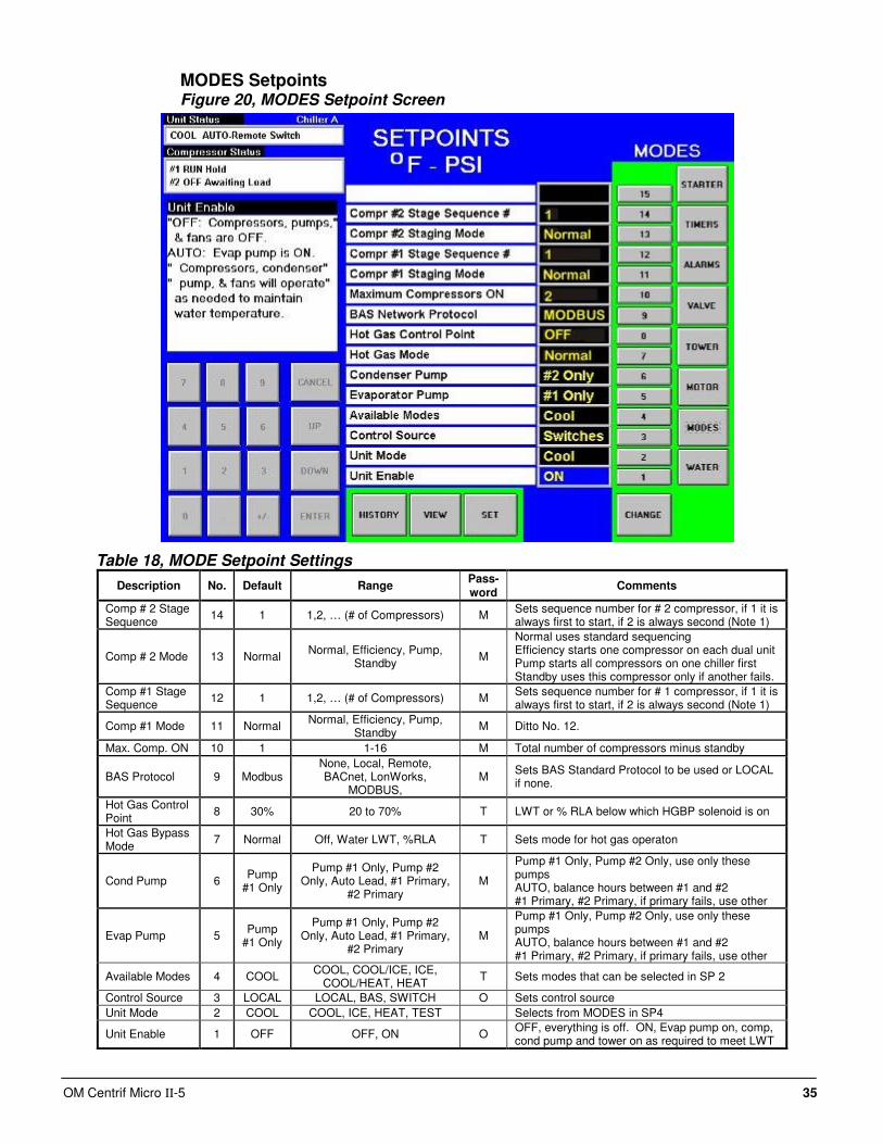
MODES Setpoints Figure 20, MODES Setpoint Screen
Table 18, MODE Setpoint Settings
Description No. Default Range Pass-word
Comments
Comp # 2 Stage Sequence
14 1 1,2, … (# of Compressors) M Sets sequence number for # 2 compressor, if 1 it is always first to start, if 2 is always second (Note 1)
Comp # 2 Mode 13 Normal Normal, Efficiency, Pump,
Standby M
Normal uses standard sequencing Efficiency starts one compressor on each dual unit Pump starts all compressors on one chiller first Standby uses this compressor only if another fails.
Comp #1 Stage Sequence
12 1 1,2, … (# of Compressors) M Sets sequence number for # 1 compressor, if 1 it is always first to start, if 2 is always second (Note 1)
Comp #1 Mode 11 Normal Normal, Efficiency, Pump,
Standby M Ditto No. 12.
Max. Comp. ON 10 1 1-16 M Total number of compressors minus standby
BAS Protocol 9 Modbus None, Local, Remote, BACnet, LonWorks,
MODBUS, M
Sets BAS Standard Protocol to be used or LOCAL if none.
Hot Gas Control Point
8 30% 20 to 70% T LWT or % RLA below which HGBP solenoid is on
Hot Gas Bypass Mode
7 Normal Off, Water LWT, %RLA T Sets mode for hot gas operaton
Cond Pump 6 Pump
#1 Only
Pump #1 Only, Pump #2 Only, Auto Lead, #1 Primary,
#2 Primary M
Pump #1 Only, Pump #2 Only, use only these pumps AUTO, balance hours between #1 and #2 #1 Primary, #2 Primary, if primary fails, use other
Evap Pump 5 Pump
#1 Only
Pump #1 Only, Pump #2 Only, Auto Lead, #1 Primary,
#2 Primary M
Pump #1 Only, Pump #2 Only, use only these pumps AUTO, balance hours between #1 and #2 #1 Primary, #2 Primary, if primary fails, use other
Available Modes 4 COOL COOL, COOL/ICE, ICE,
COOL/HEAT, HEAT T Sets modes that can be selected in SP 2
Control Source 3 LOCAL LOCAL, BAS, SWITCH O Sets control source
Unit Mode 2 COOL COOL, ICE, HEAT, TEST Selects from MODES in SP4
Unit Enable 1 OFF OFF, ON O OFF, everything is off. ON, Evap pump on, comp, cond pump and tower on as required to meet LWT
36 OM Centrif Micro ΙΙ-5
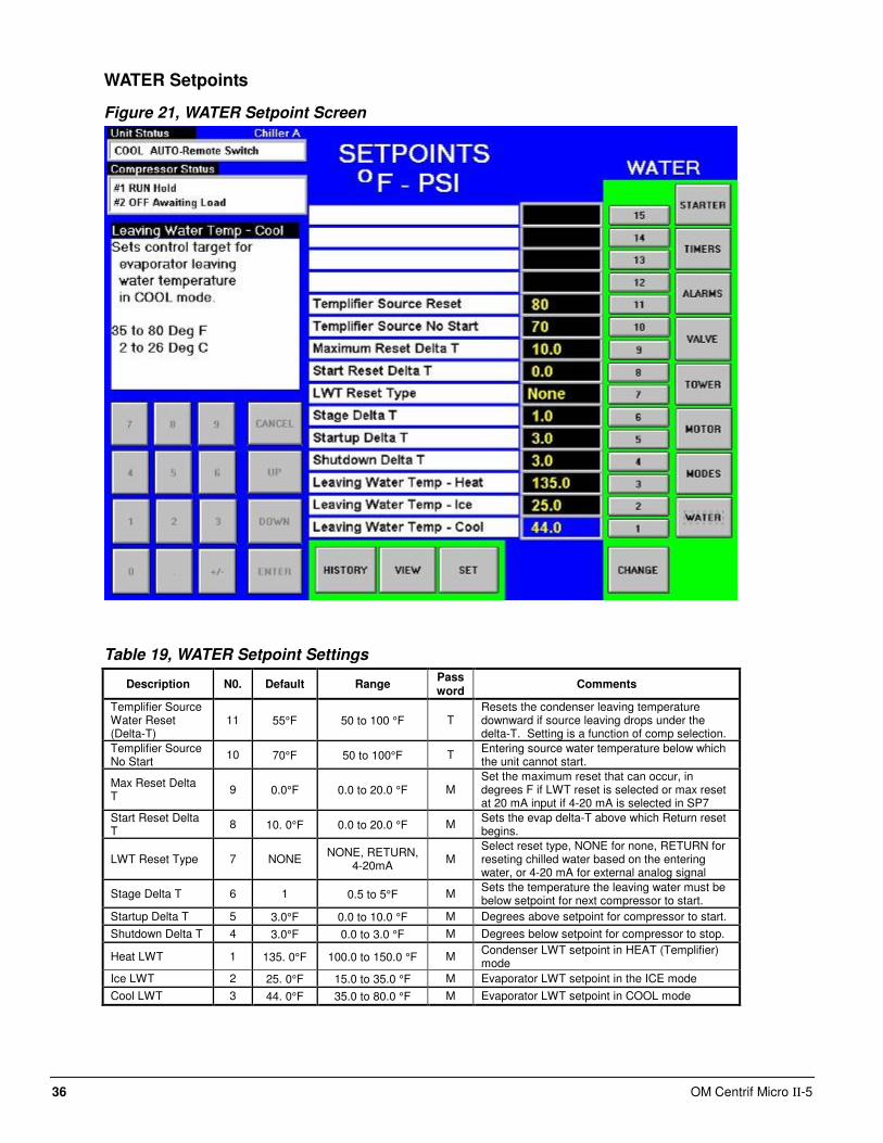
WATER Setpoints
Figure 21, WATER Setpoint Screen
Table 19, WATER Setpoint Settings
Description N0. Default Range Password
Comments
Templifier Source Water Reset (Delta-T)
11 55°F 50 to 100 °F T Resets the condenser leaving temperature downward if source leaving drops under the delta-T. Setting is a function of comp selection.
Templifier Source No Start
10 70°F 50 to 100°F T Entering source water temperature below which the unit cannot start.
Max Reset Delta T
9 0.0°F 0.0 to 20.0 °F M Set the maximum reset that can occur, in degrees F if LWT reset is selected or max reset at 20 mA input if 4-20 mA is selected in SP7
Start Reset Delta T
8 10. 0°F 0.0 to 20.0 °F M Sets the evap delta-T above which Return reset begins.
LWT Reset Type 7 NONE NONE, RETURN,
4-20mA M
Select reset type, NONE for none, RETURN for reseting chilled water based on the entering water, or 4-20 mA for external analog signal
Stage Delta T 6 1 0.5 to 5°F M Sets the temperature the leaving water must be below setpoint for next compressor to start.
Startup Delta T 5 3.0°F 0.0 to 10.0 °F M Degrees above setpoint for compressor to start.
Shutdown Delta T 4 3.0°F 0.0 to 3.0 °F M Degrees below setpoint for compressor to stop.
Heat LWT 1 135. 0°F 100.0 to 150.0 °F M Condenser LWT setpoint in HEAT (Templifier) mode
Ice LWT 2 25. 0°F 15.0 to 35.0 °F M Evaporator LWT setpoint in the ICE mode
Cool LWT 3 44. 0°F 35.0 to 80.0 °F M Evaporator LWT setpoint in COOL mode
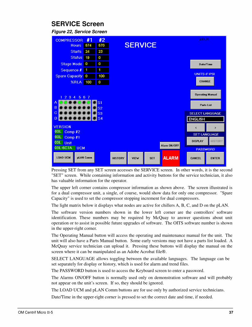
OM Centrif Micro ΙΙ-5 37
SERVICE Screen Figure 22, Service Screen
Pressing SET from any SET screen accesses the SERVICE screen. In other words, it is the second
"SET" screen. While containing information and activity buttons for the service technician, it also
has valuable information for the operator.
The upper left corner contains compressor information as shown above. The screen illustrated is
for a dual compressor unit, a single, of course, would show data for only one compressor. "Spare
Capacity" is used to set the compressor stopping increment for dual compressors.
The light matrix below it displays what nodes are active for chillers A, B, C, and D on the pLAN.
The software version numbers shown in the lower left corner are the controllers' software
identification. These numbers may be required by McQuay to answer questions about unit
operation or to assist in possible future upgrades of software. The OITS software number is shown
in the upper-right corner.
The Operating Manual button will access the operating and maintenance manual for the unit. The
unit will also have a Parts Manual button. Some early versions may not have a parts list loaded. A
McQuay service technician can upload it. Pressing these buttons will display the manual on the
screen where it can be manipulated as an Adobe Acrobat file.
SELECT LANGUAGE allows toggling between the available languages. The language can be
set separately for display or history, which is used for alarm and trend files.
The PASSWORD button is used to access the Keyboard screen to enter a password.
The Alarms ON/OFF button is normally used only on demonstration software and will probably
not appear on the unit’s screen. If so, they should be ignored.
The LOAD UCM and pLAN Comm buttons are for use only by authorized service technicians.
Date/Time in the upper-right corner is pressed to set the correct date and time, if needed.
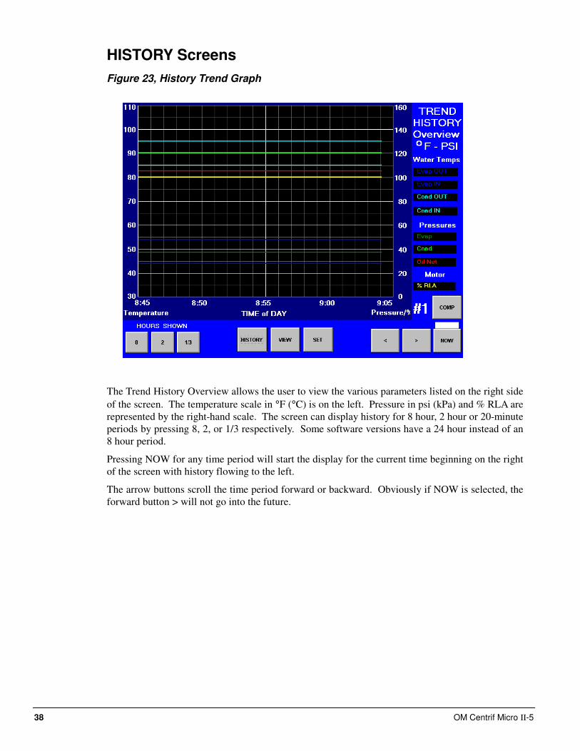
38 OM Centrif Micro ΙΙ-5
HISTORY Screens
Figure 23, History Trend Graph
The Trend History Overview allows the user to view the various parameters listed on the right side
of the screen. The temperature scale in °F (°C) is on the left. Pressure in psi (kPa) and % RLA are
represented by the right-hand scale. The screen can display history for 8 hour, 2 hour or 20-minute
periods by pressing 8, 2, or 1/3 respectively. Some software versions have a 24 hour instead of an
8 hour period.
Pressing NOW for any time period will start the display for the current time beginning on the right
of the screen with history flowing to the left.
The arrow buttons scroll the time period forward or backward. Obviously if NOW is selected, the
forward button > will not go into the future.
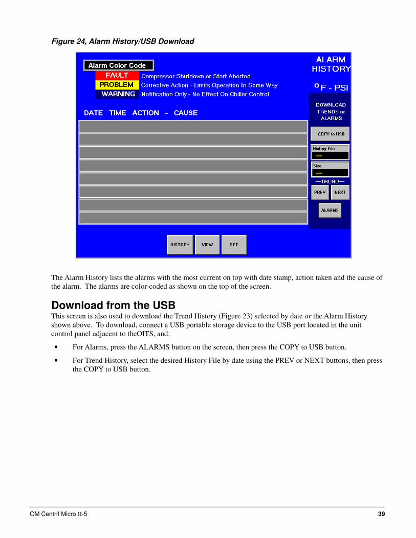
OM Centrif Micro ΙΙ-5 39
Figure 24, Alarm History/USB Download
The Alarm History lists the alarms with the most current on top with date stamp, action taken and the cause of
the alarm. The alarms are color-coded as shown on the top of the screen.
Download from the USB This screen is also used to download the Trend History (Figure 23) selected by date or the Alarm History
shown above. To download, connect a USB portable storage device to the USB port located in the unit
control panel adjacent to theOITS, and:
• For Alarms, press the ALARMS button on the screen, then press the COPY to USB button.
• For Trend History, select the desired History File by date using the PREV or NEXT buttons, then press
the COPY to USB button.
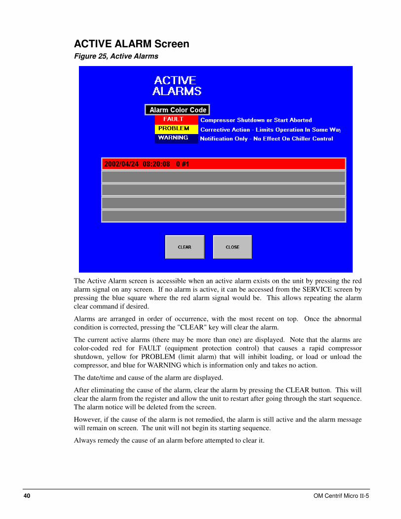
40 OM Centrif Micro ΙΙ-5
ACTIVE ALARM Screen Figure 25, Active Alarms
The Active Alarm screen is accessible when an active alarm exists on the unit by pressing the red
alarm signal on any screen. If no alarm is active, it can be accessed from the SERVICE screen by
pressing the blue square where the red alarm signal would be. This allows repeating the alarm
clear command if desired.
Alarms are arranged in order of occurrence, with the most recent on top. Once the abnormal
condition is corrected, pressing the "CLEAR" key will clear the alarm.
The current active alarms (there may be more than one) are displayed. Note that the alarms are
color-coded red for FAULT (equipment protection control) that causes a rapid compressor
shutdown, yellow for PROBLEM (limit alarm) that will inhibit loading, or load or unload the
compressor, and blue for WARNING which is information only and takes no action.
The date/time and cause of the alarm are displayed.
After eliminating the cause of the alarm, clear the alarm by pressing the CLEAR button. This will
clear the alarm from the register and allow the unit to restart after going through the start sequence.
The alarm notice will be deleted from the screen.
However, if the cause of the alarm is not remedied, the alarm is still active and the alarm message
will remain on screen. The unit will not begin its starting sequence.
Always remedy the cause of an alarm before attempted to clear it.
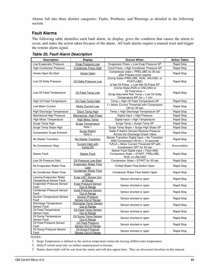
OM Centrif Micro ΙΙ-5 41
Alarms fall into three distinct categories: Faults, Problems, and Warnings as detailed in the following
section.
Fault Alarms
The following table identifies each fault alarm, its display, gives the condition that causes the alarm to
occur, and states the action taken because of the alarm. All fault alarms require a manual reset and trigger
the remote alarm signal.
Table 20, Fault Alarm Description
Description Display Occurs When: Action Taken
Low Evaporator Pressure Evap Pressure Low Evaporator Press < Low Evap Pressure SP Rapid Stop
High Condenser Pressure Condenser Press High Cond Press > High Condenser Pressure SP Rapid Stop
Vanes Open No Start Vanes Open Compressor state = PRELUBE for 30 sec
after Prelube timer expires Rapid Stop
Low Oil Delta Pressure Oil Delta Pressure Low (Comp State=PRELUBE, RUN, UNLOAD, or
POSTLUBE) & Net Oil Press < Low Net Oil Press SP
Rapid Stop
Low Oil Feed Temperature Oil Feed Temp Low
(Comp State=RUN or UNLOAD) & Oil Feed temp <
(Evap Saturated Refr Temp + Low Oil Delta Temperature SP) for > 1 min
Rapid Stop
High Oil Feed Temperature Oil Feed Temp High Temp > High Oil Feed Temperature SP Rapid Stop
Low Motor Current Motor Current Low I < Motor Current Threshold with Compressor
ON for 30 sec Rapid Stop
High Discharge Temperature Disch Temp High Temp > High Discharge Temperature SP Rapid Stop
Mechanical High Pressure Mechanical High Press Digital Input = High Pressure Rapid Stop
High Motor Temperature High Motor Temp Digital Input = High Temperature Rapid Stop
Surge Temp High Surge Temp > Surge Temp SP Rapid Stop
Surge Temp Slope High
Surge Temperature Note 1 Surge Temp Slope > Surge High Slope SP Rapid Stop
Compressor Surge Eminent Surge Switch
Note 2 Delta-P Switch Senses Reverse Pressure
Across the Discharge Check Valve Rapid Stop
No Starter Transition No Starter Transition Starter Transition Digital Input = No Transition
AND Compressor ON for > 15 seconds Rapid Stop
No Compressor Stop Current High with
Comp Off %RLA > Motor Current Threshold SP with
Compressor OFF for 30 sec Annunciation
Starter Fault Starter Fault Starter Fault Digital Input = Fault AND
Compressor State = START, PRELUBE, RUN, or UNLOAD
Rapid Stop
Low Oil Pressure Start Oil Pressure Low-Start Compressor State = START for 30 sec Rapid Stop
No Evaporator Water Flow Evaporator Water Flow
Loss Chilled Water Flow Switch Open Rapid Stop
No Condenser Water Flow Condenser Water Flow
Loss Condenser Water Flow Switch Open Rapid Stop
Leaving Evaporator Water Temperature Sensor Fault
Evap LWT Sensor Out of Range
Sensor shorted or open Rapid Stop
Evaporator Pressure Sensor Fault
Evap Pressure Sensor Out of Range
Sensor shorted or open Rapid Stop
Condenser Pressure Sensor Fault
Cond Pressure Sensor Out of Range
Sensor shorted or open Rapid Stop
Suction Temperature Sensor Fault
Suction Pressure Sensor Out of Range
Sensor shorted or open Rapid Stop
Discharge Temperature Sensor Fault
Discharge Temp Sensor Out of Range
Sensor shorted or open Rapid Stop
Oil Feed Temperature Sensor Fault
Oil Feed Temp Sensor Out of Range
Sensor shorted or open Rapid Stop
Oil Sump Temperature Sensor Fault
Oil Sump Temp Sensor Out of Range
Sensor shorted or open Rapid Stop
Oil Feed Pressure Sensor Fault
Oil Feed Pressure Sensor Out of Range
Sensor shorted or open Rapid Stop
Oil Sump Pressure Sensor Fault
Oil Sump Pressure Sensor Out of Range
Sensor shorted or open Rapid Stop
NOTES:
1. Surge Temperature is defined as the suction temperature minus the leaving chilled water temperature.
2. Delta-P switch used only on chillers manufactured in Europe.
3. Starter alarm faults will be sent from the starter and will also appear here. They are discussed elsewhere in this manual.
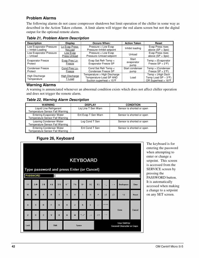
42 OM Centrif Micro ΙΙ-5
Problem Alarms
The following alarms do not cause compressor shutdown but limit operation of the chiller in some way as
described in the Action Taken column. A limit alarm will trigger the red alarm screen but not the digital
output for the optional remote alarm.
Table 21, Problem Alarm Description
Description Display Occurs When: Action Taken Reset
Low Evaporator Pressure – Inhibit Loading
Lo Evap Press-NoLoad
Pressure < Low Evap Pressure–Inhibit setpoint
Inhibit loading Evap Press rises above (SP + 3psi)
Low Evaporator Pressure – Unload
Low Evap Press-Unload
Pressure < Low Evap Pressure–Unload setpoint
Unload Evap Press rises above (SP + 3psi)
Evaporator Freeze Protect
Evap Pres Lo-Freeze
Evap Sat Refr Temp < Evaporator Freeze SP
Start evaporator
pump
Temp > (Evaporator Freeze SP + 2°F)
Condenser Freeze Protect
Cond Pres Lo-Freeze
Cond Sat Refr Temp < Condenser Freeze SP
Start condenser pump
Temp > (Condenser Freeze SP + 2°F)
High Discharge Temperature
High Discharge T-Load
Temperature > High Discharge Temperature-Load SP AND Suction superheat < 15°F
Load Temp < (High Dsch
Temp Load SP – 3°F) OR Superheat > 18°F
Warning Alarms A warning is annunciated whenever an abnormal condition exists which does not affect chiller operation
and does not trigger the remote alarm.
Table 22, Warning Alarm Description
WARNING DISPLAY CONDITION
Liquid Line Refrigerant Temperature Sensor Fall Warning
Liq Line T Sen Warn Sensor is shorted or open
Entering Evaporator Water Temperature Sensor Fall Warning
Ent Evap T Sen Warn Sensor is shorted or open
Leaving Condenser Water Temperature Sensor Fail Warning
Lvg Cond T Sen Sensor is shorted or open
Entering Condenser Water Temperature Sensor Fail Warning
Ent Cond T Sen Sensor is shorted or open
Figure 26, Keyboard
The keyboard is for
entering the password
when attempting to
enter or change a
setpoint. This screen
is accessed from the
SERVICE screen by
pressing the
PASSWORD button.
It is automatically
accessed when making
a change to a setpoint
on any SET screen.
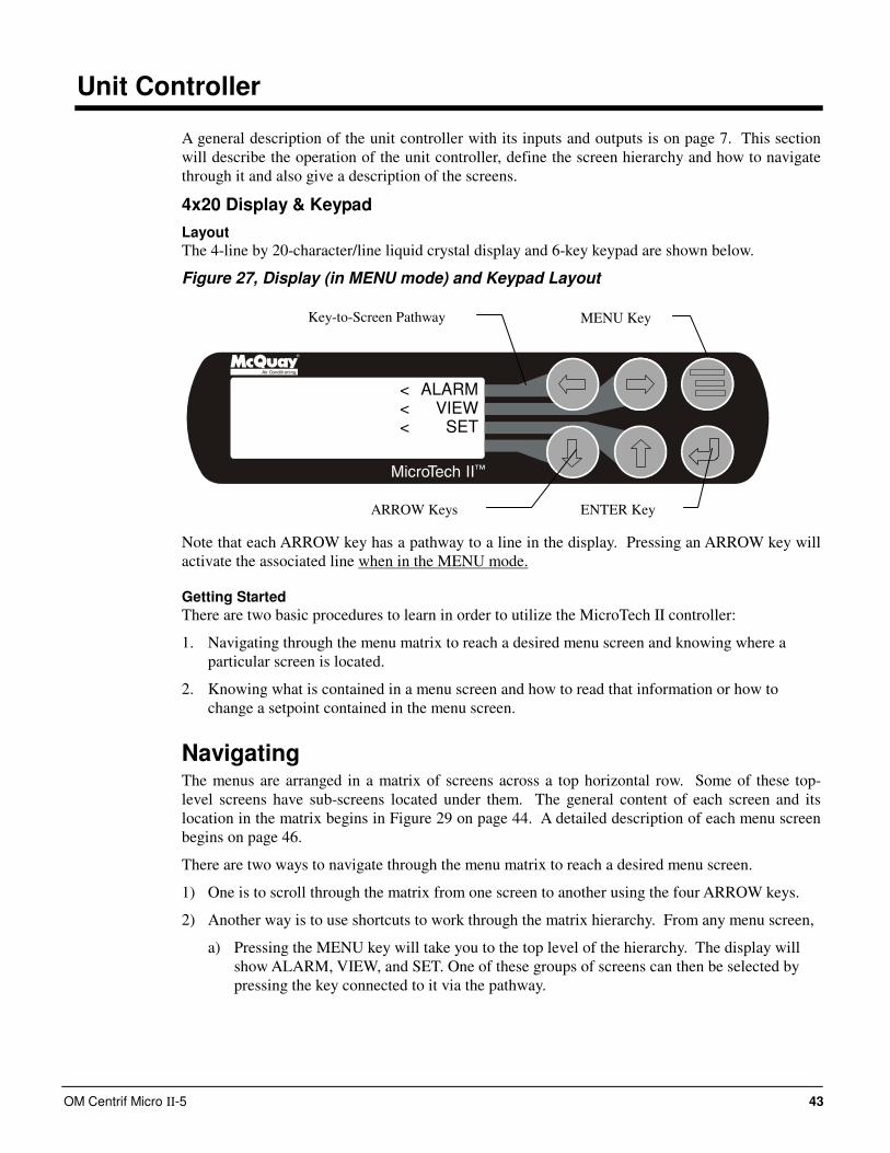
OM Centrif Micro ΙΙ-5 43
Unit Controller
A general description of the unit controller with its inputs and outputs is on page 7. This section
will describe the operation of the unit controller, define the screen hierarchy and how to navigate
through it and also give a description of the screens.
4x20 Display & Keypad
Layout
The 4-line by 20-character/line liquid crystal display and 6-key keypad are shown below.
Figure 27, Display (in MENU mode) and Keypad Layout
Air Conditioning
ALARMVIEW
SET
<<<
Note that each ARROW key has a pathway to a line in the display. Pressing an ARROW key will
activate the associated line when in the MENU mode.
Getting Started
There are two basic procedures to learn in order to utilize the MicroTech II controller:
1. Navigating through the menu matrix to reach a desired menu screen and knowing where a
particular screen is located.
2. Knowing what is contained in a menu screen and how to read that information or how to
change a setpoint contained in the menu screen.
Navigating The menus are arranged in a matrix of screens across a top horizontal row. Some of these top-
level screens have sub-screens located under them. The general content of each screen and its
location in the matrix begins in Figure 29 on page 44. A detailed description of each menu screen
begins on page 46.
There are two ways to navigate through the menu matrix to reach a desired menu screen.
1) One is to scroll through the matrix from one screen to another using the four ARROW keys.
2) Another way is to use shortcuts to work through the matrix hierarchy. From any menu screen,
a) Pressing the MENU key will take you to the top level of the hierarchy. The display will
show ALARM, VIEW, and SET. One of these groups of screens can then be selected by
pressing the key connected to it via the pathway.
ENTER Key
MENU Key
ARROW Keys
Key-to-Screen Pathway
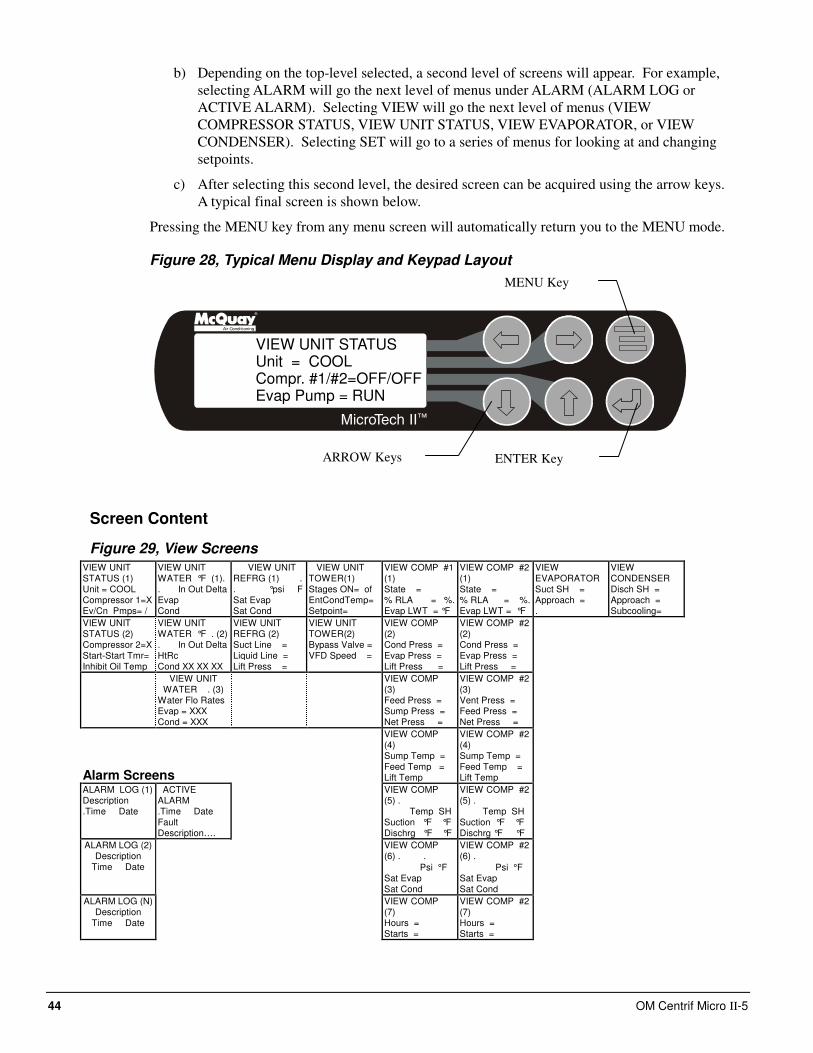
44 OM Centrif Micro ΙΙ-5
b) Depending on the top-level selected, a second level of screens will appear. For example,
selecting ALARM will go the next level of menus under ALARM (ALARM LOG or
ACTIVE ALARM). Selecting VIEW will go the next level of menus (VIEW
COMPRESSOR STATUS, VIEW UNIT STATUS, VIEW EVAPORATOR, or VIEW
CONDENSER). Selecting SET will go to a series of menus for looking at and changing
setpoints.
c) After selecting this second level, the desired screen can be acquired using the arrow keys.
A typical final screen is shown below.
Pressing the MENU key from any menu screen will automatically return you to the MENU mode.
Figure 28, Typical Menu Display and Keypad Layout
Air Conditioning
VIEW UNIT STATUSUnit = COOLCompr. #1/#2=OFF/OFFEvap Pump = RUN
Screen Content
Figure 29, View Screens VIEW UNIT STATUS (1) Unit = COOL Compressor 1=X Ev/Cn Pmps= /
VIEW UNIT WATER °F (1). . In Out Delta Evap Cond
VIEW UNIT REFRG (1) . . °psi F Sat Evap Sat Cond
VIEW UNIT TOWER(1) Stages ON= of EntCondTemp= Setpoint=
VIEW COMP #1 (1) State = % RLA = %. Evap LWT = °F
VIEW COMP #2 (1) State = % RLA = %. Evap LWT = °F
VIEW EVAPORATOR Suct SH = Approach = .
VIEW CONDENSER Disch SH = Approach = Subcooling=
VIEW UNIT STATUS (2) Compressor 2=X Start-Start Tmr= Inhibit Oil Temp
VIEW UNIT WATER °F . (2) . In Out Delta HtRc Cond XX XX XX
VIEW UNIT REFRG (2) Suct Line = Liquid Line = Lift Press =
VIEW UNIT TOWER(2) Bypass Valve = VFD Speed =
VIEW COMP (2) Cond Press = Evap Press = Lift Press =
VIEW COMP #2 (2) Cond Press = Evap Press = Lift Press =
VIEW UNIT WATER . (3)
Water Flo Rates Evap = XXX Cond = XXX
VIEW COMP (3) Feed Press = Sump Press = Net Press =
VIEW COMP #2 (3) Vent Press = Feed Press = Net Press =
Alarm Screens
VIEW COMP (4) Sump Temp = Feed Temp = Lift Temp
VIEW COMP #2 (4) Sump Temp = Feed Temp = Lift Temp
ALARM LOG (1) Description .Time Date
ACTIVE ALARM .Time Date Fault Description….
VIEW COMP (5) . Temp SH Suction °F °F Dischrg °F °F
VIEW COMP #2 (5) . Temp SH Suction °F °F Dischrg °F °F
ALARM LOG (2) Description
Time Date
VIEW COMP (6) . .
Psi °F Sat Evap Sat Cond
VIEW COMP #2 (6) .
Psi °F Sat Evap Sat Cond
ALARM LOG (N) Description
Time Date
VIEW COMP (7) Hours = Starts =
VIEW COMP #2 (7) Hours = Starts =
MENU Key
ENTER Key ARROW Keys
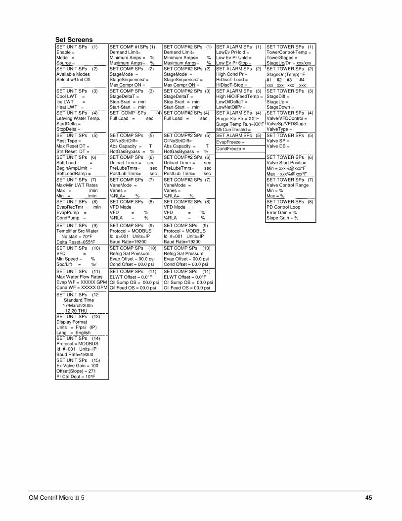
OM Centrif Micro ΙΙ-5 45
Set Screens SET UNIT SPs (1) Enable = Mode = Source =
SET COMP #1SPs (1) Demand Limit= Minimum Amps = % Maximum Amps= %
SET COMP#2 SPs (1) Demand Limit= Minimum Amps= % Maximum Amps= %
SET ALARM SPs (1) LowEv PrHold = Low Ev Pr Unld = Low Ev Pr Stop =
SET TOWER SPs (1) TowerControl-Temp = TowerStages = StageUp/Dn = xxx/xxx
SET UNIT SPs (2) Available Modes Select w/Unit Off
SET COMP SPs (2) StageMode = StageSequence# = Max Compr ON =
SET COMP#2 SPs (2) StageMode = StageSequence# = Max Compr ON =
SET ALARM SPs (2) High Cond Pr = HiDiscT-Load = HiDiscT-Stop =
SET TOWER SPs (2)
StageOn(Temp) °F #1 #2 #3 #4 xxx xxx xxx xxx
SET UNIT SPs (3) Cool LWT = Ice LWT = Heat LWT =
SET COMP SPs (3) StageDeltaT = Stop-Srart = min Start-Start = min
SET COMP#2 SPs (3) StageDeltaT = Stop-Srart = min Start-Start = min
SET ALARM SPs (3) High HiOilFeedTemp = LowOilDeltaT = LowNetOilPr =
SET TOWER SPs (3) StageDiff = StageUp = StageDown =
SET UNIT SPs (4) Leaving Water Temp. StartDelta = StopDelta =
SET COMP SPs (4) Full Load = sec
SET COMP#2 SPs (4) Full Load = sec
SET ALARM SPs (4)
Surge Slp Str = XX°F
Surge Temp Run=XX°F MtrCurrThrshld =
SET TOWER SPs (4) Valve/VFDControl = ValveSp/VFDStage ValveType =
SET UNIT SPs (5) Rest Type = Max Reset DT = Strt Reset DT =
SET COMP SPs (5) OilNoStrtDiff= Abs Capacity = T HotGasBypass = %
SET COMP#2 SPs (5) OilNoStrtDiff= Abs Capacity = T HotGasBypass = %
SET TOWER SPs (5) Valve SP = Valve DB =
SET UNIT SPs (6) Soft Load = BeginAmpLimit = SoftLoadRamp =
SET COMP SPs (6) Unload Timer = sec PreLubeTmrs= sec PostLub Tmrs= sec
SET COMP#2 SPs (6) Unload Timer = sec PreLubeTmrs= sec PostLub Tmrs= sec
SET TOWER SPs (6) Valve Start Position
Min = xxx%@xxx°F
Max = xxx%@xxx°F
SET UNIT SPs (7) Max/Min LWT Rates Max = /min Min = /min
SET COMP SPs (7) VaneMode = Vanes = %RLA= %
SET COMP#2 SPs (7) VaneMode = Vanes = %RLA= %
SET TOWER SPs (7) Valve Control Range Min = % Max = %
SET UNIT SPs (8) EvapRecTmr = min EvapPump = CondPump =
SET COMP SPs (8) VFD Mode = VFD = % %RLA = %
SET COMP#2 SPs (8) VFD Mode = VFD = % %RLA = %
SET TOWER SPs (8) PD Control Loop Error Gain = % Slope Gain = %
SET UNIT SPs (9) Templifier Src Water
No start = 70°F
Delta Reset=055°F
SET COMP SPs (9) Protocol = MODBUS Id #=001 Units=IP Baud Rate=19200
SET COMP SPs (9) Protocol = MODBUS Id #=001 Units=IP Baud Rate=19200
SET UNIT SPs (10) VFD = Min Speed = % Spd/Lift = %/
SET COMP SPs (10) Refrig Sat Pressure Evap Offset = 00.0 psi Cond Ofset = 00.0 psi
SET COMP SPs (10) Refrig Sat Pressure Evap Offset = 00.0 psi Cond Ofset = 00.0 psi
SET UNIT SPs (11) Max Water Flow Rates Evap WF = XXXXX GPM Cond WF = XXXXX GPM
SET COMP SPs (11)
ELWT Offset = 0.0°F Oil Sump OS = 00.0 psi Oil Feed OS = 00.0 psi
SET COMP SPs (11)
ELWT Offset = 0.0°F Oil Sump OS = 00.0 psi Oil Feed OS = 00.0 psi
SET ALARM SPs (5)
EvapFreeze =
CondFreeze =
SET UNIT SPs (12 Standard Time 17/March/2005 12:20 THU
SET UNIT SPs (13) Display Format Units = F/psi (IP) Lang = English
SET UNIT SPs (14) Protocol = MODBUS Id #=001 Units=IP Baud Rate=19200
SET UNIT SPs (15) Ex-Valve Gain = 100 Offset(Slope) = 271
Pr Ctrl Dout = 10°F
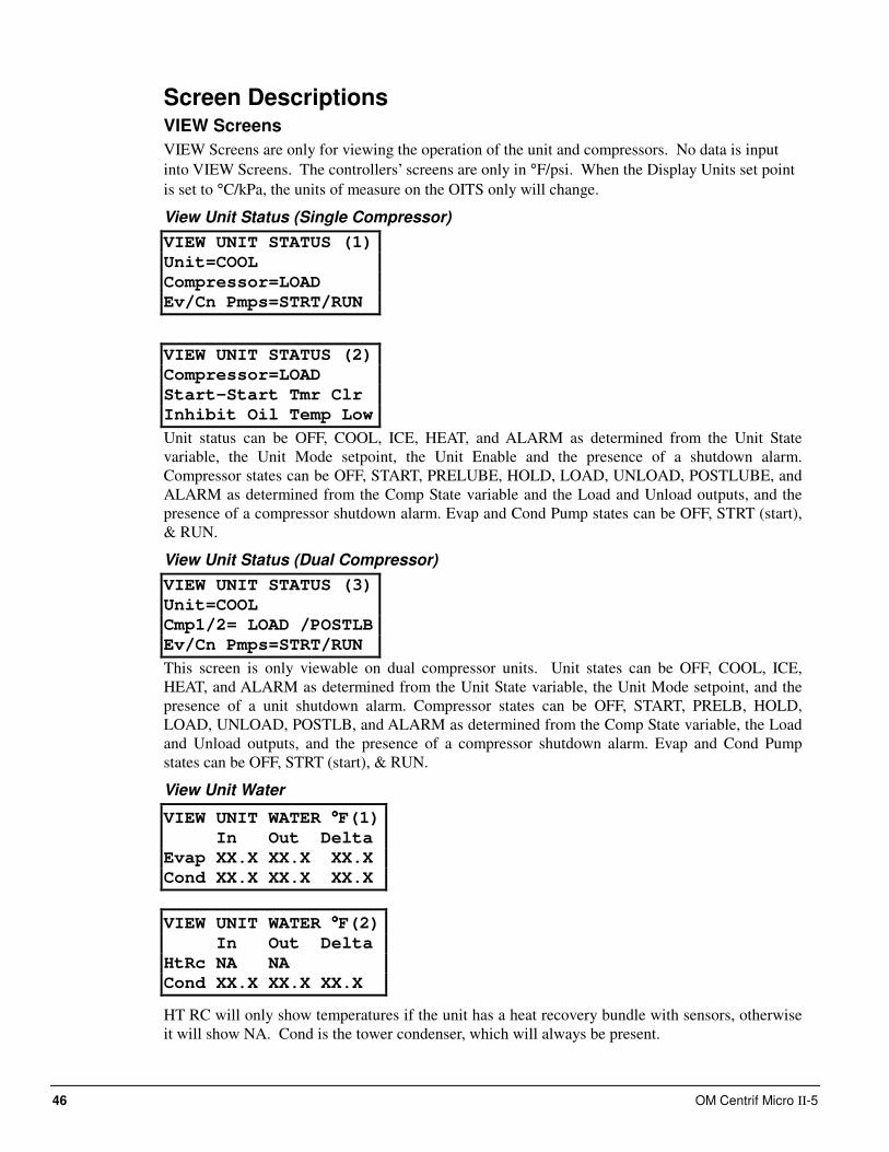
46 OM Centrif Micro ΙΙ-5
Screen Descriptions VIEW Screens
VIEW Screens are only for viewing the operation of the unit and compressors. No data is input
into VIEW Screens. The controllers’ screens are only in °F/psi. When the Display Units set point
is set to °C/kPa, the units of measure on the OITS only will change.
View Unit Status (Single Compressor)
VIEW UNIT STATUS (1)
Unit=COOL
Compressor=LOAD
Ev/Cn Pmps=STRT/RUN
VIEW UNIT STATUS (2)
Compressor=LOAD
Start-Start Tmr Clr
Inhibit Oil Temp Low
Unit status can be OFF, COOL, ICE, HEAT, and ALARM as determined from the Unit State
variable, the Unit Mode setpoint, the Unit Enable and the presence of a shutdown alarm.
Compressor states can be OFF, START, PRELUBE, HOLD, LOAD, UNLOAD, POSTLUBE, and
ALARM as determined from the Comp State variable and the Load and Unload outputs, and the
presence of a compressor shutdown alarm. Evap and Cond Pump states can be OFF, STRT (start),
& RUN.
View Unit Status (Dual Compressor)
VIEW UNIT STATUS (3)
Unit=COOL
Cmp1/2= LOAD /POSTLB
Ev/Cn Pmps=STRT/RUN
This screen is only viewable on dual compressor units. Unit states can be OFF, COOL, ICE,
HEAT, and ALARM as determined from the Unit State variable, the Unit Mode setpoint, and the
presence of a unit shutdown alarm. Compressor states can be OFF, START, PRELB, HOLD,
LOAD, UNLOAD, POSTLB, and ALARM as determined from the Comp State variable, the Load
and Unload outputs, and the presence of a compressor shutdown alarm. Evap and Cond Pump
states can be OFF, STRT (start), & RUN.
View Unit Water
VIEW UNIT WATER °°°°F(1)
In Out Delta
Evap XX.X XX.X XX.X
Cond XX.X XX.X XX.X
VIEW UNIT WATER °°°°F(2)
In Out Delta
HtRc NA NA
Cond XX.X XX.X XX.X
HT RC will only show temperatures if the unit has a heat recovery bundle with sensors, otherwise
it will show NA. Cond is the tower condenser, which will always be present.
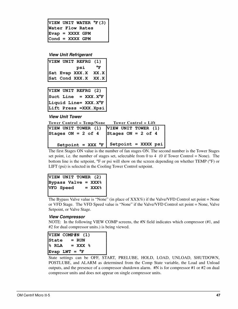
OM Centrif Micro ΙΙ-5 47
VIEW UNIT WATER °°°°F(3)
Water Flow Rates
Evap = XXXX GPM
Cond = XXXX GPM
View Unit Refrigerant
VIEW UNIT REFRG (1)
psi °°°°F
Sat Evap XXX.X XX.X
Sat Cond XXX.X XX.X
VIEW UNIT REFRG (2)
Suct Line = XXX.X°°°°F
Liquid Line= XXX.X°°°°F
Lift Press =XXX.Xpsi
View Unit Tower
Tower Control = Temp/None Tower Control = Lift
VIEW UNIT TOWER (1) VIEW UNIT TOWER (1)
Stages ON = 2 of 4 Stages ON = 2 of 4
Setpoint = XXX °°°°F Setpoint = XXXX psi
The first Stages ON value is the number of fan stages ON. The second number is the Tower Stages
set point, i.e. the number of stages set, selectable from 0 to 4 (0 if Tower Control = None). The
bottom line is the setpoint, °F or psi will show on the screen depending on whether TEMP (°F) or
LIFT (psi) is selected in the Cooling Tower Control setpoint.
VIEW UNIT TOWER (2)
Bypass Valve = XXX%
VFD Speed = XXX%
The Bypass Valve value is “None” (in place of XXX%) if the Valve/VFD Control set point = None
or VFD Stage. The VFD Speed value is “None” if the Valve/VFD Control set point = None, Valve
Setpoint, or Valve Stage.
View Compressor NOTE: In the following VIEW COMP screens, the #N field indicates which compressor (#1, and
#2 for dual compressor units.) is being viewed.
VIEW COMP#N (1)
State = RUN
% RLA = XXX %
Evap LWT = °°°°F
State settings can be OFF, START, PRELUBE, HOLD, LOAD, UNLOAD, SHUTDOWN,
POSTLUBE, and ALARM as determined from the Comp State variable, the Load and Unload
outputs, and the presence of a compressor shutdown alarm. #N is for compressor #1 or #2 on dual
compressor units and does not appear on single compressor units.
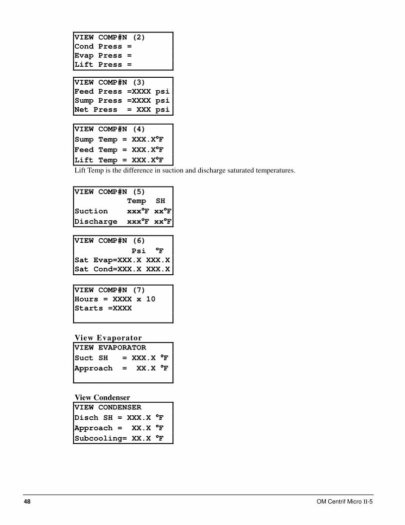
48 OM Centrif Micro ΙΙ-5
VIEW COMP#N (2)
Cond Press =
Evap Press =
Lift Press =
VIEW COMP#N (3)
Feed Press =XXXX psi
Sump Press =XXXX psi
Net Press = XXX psi
VIEW COMP#N (4)
Sump Temp = XXX.X°°°°F
Feed Temp = XXX.X°°°°F
Lift Temp = XXX.X°°°°F
Lift Temp is the difference in suction and discharge saturated temperatures.
VIEW COMP#N (5)
Temp SH
Suction xxx°°°°F xx°°°°F
Discharge xxx°°°°F xx°°°°F
VIEW COMP#N (6)
Psi °°°°F
Sat Evap=XXX.X XXX.X
Sat Cond=XXX.X XXX.X
VIEW COMP#N (7)
Hours = XXXX x 10
Starts =XXXX
View Evaporator
VIEW EVAPORATOR
Suct SH = XXX.X °°°°F
Approach = XX.X °°°°F
View Condenser
VIEW CONDENSER
Disch SH = XXX.X °°°°F
Approach = XX.X °°°°F
Subcooling= XX.X °°°°F
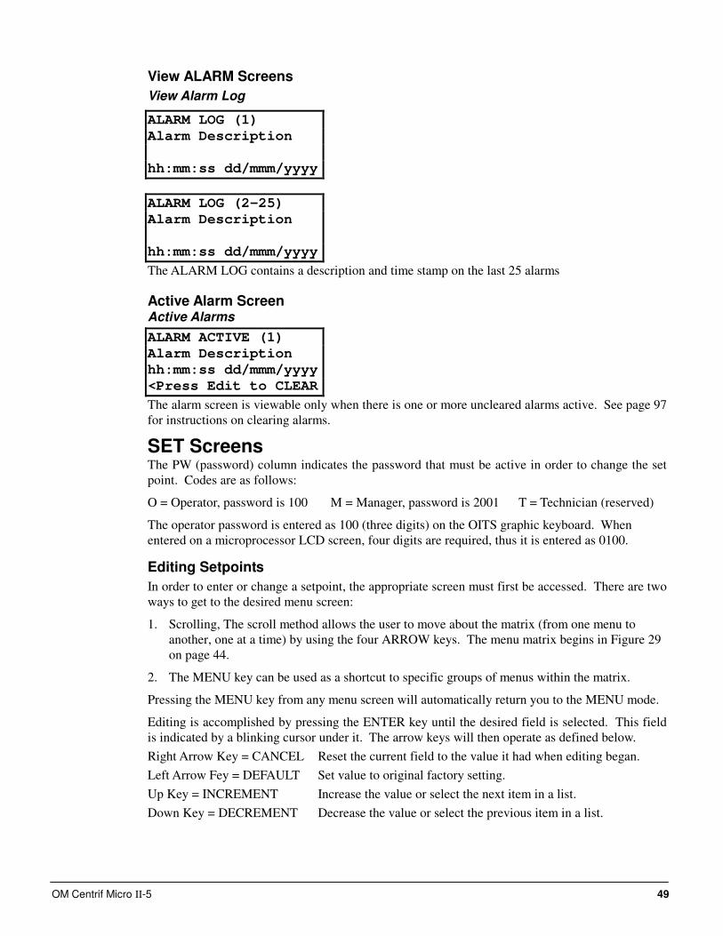
OM Centrif Micro ΙΙ-5 49
View ALARM Screens
View Alarm Log
ALARM LOG (1)
Alarm Description
hh:mm:ss dd/mmm/yyyy
ALARM LOG (2-25)
Alarm Description
hh:mm:ss dd/mmm/yyyy
The ALARM LOG contains a description and time stamp on the last 25 alarms
Active Alarm Screen Active Alarms
ALARM ACTIVE (1)
Alarm Description
hh:mm:ss dd/mmm/yyyy
<Press Edit to CLEAR
The alarm screen is viewable only when there is one or more uncleared alarms active. See page 97
for instructions on clearing alarms.
SET Screens The PW (password) column indicates the password that must be active in order to change the set
point. Codes are as follows:
O = Operator, password is 100 M = Manager, password is 2001 T = Technician (reserved)
The operator password is entered as 100 (three digits) on the OITS graphic keyboard. When
entered on a microprocessor LCD screen, four digits are required, thus it is entered as 0100.
Editing Setpoints
In order to enter or change a setpoint, the appropriate screen must first be accessed. There are two
ways to get to the desired menu screen:
1. Scrolling, The scroll method allows the user to move about the matrix (from one menu to
another, one at a time) by using the four ARROW keys. The menu matrix begins in Figure 29
on page 44.
2. The MENU key can be used as a shortcut to specific groups of menus within the matrix.
Pressing the MENU key from any menu screen will automatically return you to the MENU mode.
Editing is accomplished by pressing the ENTER key until the desired field is selected. This field
is indicated by a blinking cursor under it. The arrow keys will then operate as defined below.
Right Arrow Key = CANCEL Reset the current field to the value it had when editing began.
Left Arrow Fey = DEFAULT Set value to original factory setting.
Up Key = INCREMENT Increase the value or select the next item in a list.
Down Key = DECREMENT Decrease the value or select the previous item in a list.
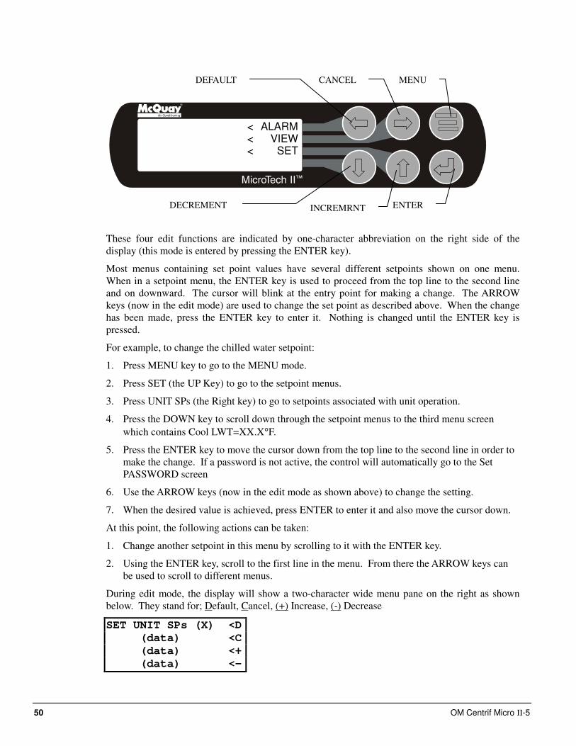
50 OM Centrif Micro ΙΙ-5
Air Conditioning
ALARMVIEW
SET
<<<
These four edit functions are indicated by one-character abbreviation on the right side of the
display (this mode is entered by pressing the ENTER key).
Most menus containing set point values have several different setpoints shown on one menu.
When in a setpoint menu, the ENTER key is used to proceed from the top line to the second line
and on downward. The cursor will blink at the entry point for making a change. The ARROW
keys (now in the edit mode) are used to change the set point as described above. When the change
has been made, press the ENTER key to enter it. Nothing is changed until the ENTER key is
pressed.
For example, to change the chilled water setpoint:
1. Press MENU key to go to the MENU mode.
2. Press SET (the UP Key) to go to the setpoint menus.
3. Press UNIT SPs (the Right key) to go to setpoints associated with unit operation.
4. Press the DOWN key to scroll down through the setpoint menus to the third menu screen
which contains Cool LWT=XX.X°F.
5. Press the ENTER key to move the cursor down from the top line to the second line in order to
make the change. If a password is not active, the control will automatically go to the Set
PASSWORD screen
6. Use the ARROW keys (now in the edit mode as shown above) to change the setting.
7. When the desired value is achieved, press ENTER to enter it and also move the cursor down.
At this point, the following actions can be taken:
1. Change another setpoint in this menu by scrolling to it with the ENTER key.
2. Using the ENTER key, scroll to the first line in the menu. From there the ARROW keys can
be used to scroll to different menus.
During edit mode, the display will show a two-character wide menu pane on the right as shown
below. They stand for; Default, Cancel, (+) Increase, (-) Decrease
SET UNIT SPs (X) <D
(data) <C
(data) <+
(data) <-
MENU CANCEL DEFAULT
ENTER INCREMRNT DECREMENT
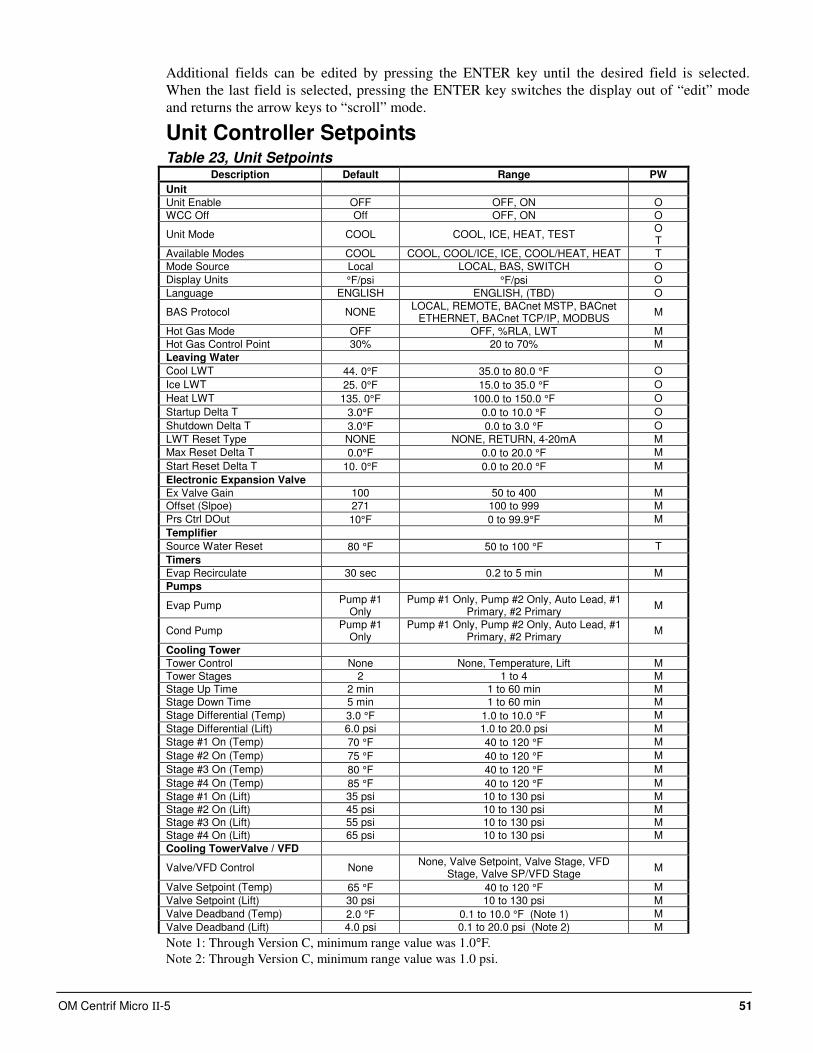
OM Centrif Micro ΙΙ-5 51
Additional fields can be edited by pressing the ENTER key until the desired field is selected.
When the last field is selected, pressing the ENTER key switches the display out of “edit” mode
and returns the arrow keys to “scroll” mode.
Unit Controller Setpoints Table 23, Unit Setpoints
Description Default Range PW
Unit
Unit Enable OFF OFF, ON O
WCC Off Off OFF, ON O
Unit Mode COOL COOL, ICE, HEAT, TEST O T
Available Modes COOL COOL, COOL/ICE, ICE, COOL/HEAT, HEAT T
Mode Source Local LOCAL, BAS, SWITCH O
Display Units °F/psi °F/psi O
Language ENGLISH ENGLISH, (TBD) O
BAS Protocol NONE LOCAL, REMOTE, BACnet MSTP, BACnet
ETHERNET, BACnet TCP/IP, MODBUS M
Hot Gas Mode OFF OFF, %RLA, LWT M
Hot Gas Control Point 30% 20 to 70% M
Leaving Water
Cool LWT 44. 0°F 35.0 to 80.0 °F O
Ice LWT 25. 0°F 15.0 to 35.0 °F O
Heat LWT 135. 0°F 100.0 to 150.0 °F O
Startup Delta T 3.0°F 0.0 to 10.0 °F O
Shutdown Delta T 3.0°F 0.0 to 3.0 °F O
LWT Reset Type NONE NONE, RETURN, 4-20mA M
Max Reset Delta T 0.0°F 0.0 to 20.0 °F M
Start Reset Delta T 10. 0°F 0.0 to 20.0 °F M
Electronic Expansion Valve
Ex Valve Gain 100 50 to 400 M
Offset (Slpoe) 271 100 to 999 M
Prs Ctrl DOut 10°F 0 to 99.9°F M
Templifier
Source Water Reset 80 °F 50 to 100 °F T
Timers
Evap Recirculate 30 sec 0.2 to 5 min M
Pumps
Evap Pump Pump #1
Only Pump #1 Only, Pump #2 Only, Auto Lead, #1
Primary, #2 Primary M
Cond Pump Pump #1
Only Pump #1 Only, Pump #2 Only, Auto Lead, #1
Primary, #2 Primary M
Cooling Tower
Tower Control None None, Temperature, Lift M
Tower Stages 2 1 to 4 M
Stage Up Time 2 min 1 to 60 min M
Stage Down Time 5 min 1 to 60 min M
Stage Differential (Temp) 3.0 °F 1.0 to 10.0 °F M
Stage Differential (Lift) 6.0 psi 1.0 to 20.0 psi M
Stage #1 On (Temp) 70 °F 40 to 120 °F M
Stage #2 On (Temp) 75 °F 40 to 120 °F M
Stage #3 On (Temp) 80 °F 40 to 120 °F M
Stage #4 On (Temp) 85 °F 40 to 120 °F M
Stage #1 On (Lift) 35 psi 10 to 130 psi M
Stage #2 On (Lift) 45 psi 10 to 130 psi M
Stage #3 On (Lift) 55 psi 10 to 130 psi M
Stage #4 On (Lift) 65 psi 10 to 130 psi M
Cooling TowerValve / VFD
Valve/VFD Control None None, Valve Setpoint, Valve Stage, VFD
Stage, Valve SP/VFD Stage M
Valve Setpoint (Temp) 65 °F 40 to 120 °F M
Valve Setpoint (Lift) 30 psi 10 to 130 psi M
Valve Deadband (Temp) 2.0 °F 0.1 to 10.0 °F (Note 1) M
Valve Deadband (Lift) 4.0 psi 0.1 to 20.0 psi (Note 2) M
Note 1: Through Version C, minimum range value was 1.0°F.
Note 2: Through Version C, minimum range value was 1.0 psi.
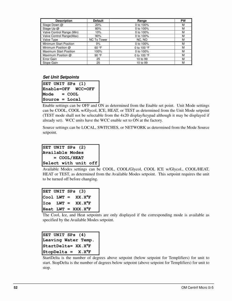
52 OM Centrif Micro ΙΙ-5
Description Default Range PW
Stage Down @ 20% 0 to 100% M
Stage Up @ 80% 0 to 100% M
Valve Control Range (Min) 10% 0 to 100% M
Valve Control Range(Max) 90% 0 to 100% M
Valve Type NC To Tower NC, NO M
Minimum Start Position 0% 0 to 100% M
Minimum Position @ 60 °F 0 to 100 °F M
Maximum Start Position 100% 0 to 100% M
Maximum Position @ 90 °F 0 to 100 °F M
Error Gain 25 10 to 99 M
Slope Gain 25 10 to 99 M
Set Unit Setpoints
SET UNIT SPs (1)
Enable=OFF WCC=OFF
Mode = COOL
Source = Local
Enable settings can be OFF and ON as determined from the Enable set point. Unit Mode settings
can be COOL, COOL w/Glycol, ICE, HEAT, or TEST as determined from the Unit Mode setpoint
(TEST mode shall not be selectable from the 4x20 display/keypad although it may be displayed if
already set). WCC units have the WCC enable set to ON at the factory.
Source settings can be LOCAL, SWITCHES, or NETWORK as determined from the Mode Source
setpoint.
SET UNIT SPs (2)
Available Modes
= COOL/HEAT
Select with unit off
Available Modes settings can be COOL, COOL/Glycol, COOL ICE w/Glycol., COOL/HEAT,
HEAT or TEST, as determined from the Available Modes setpoint. This setpoint requires the unit
to be turned off before changing.
SET UNIT SPs (3)
Cool LWT = XX.X°°°°F
Ice LWT = XX.X°°°°F
Heat LWT = XXX.X°°°°F
The Cool, Ice, and Heat setpoints are only displayed if the corresponding mode is available as
specified by the Available Modes setpoint.
SET UNIT SPs (4)
Leaving Water Temp.
StartDelta= XX.X°°°°F
StopDelta = X.X°°°°F
StartDelta is the number of degrees above setpoint (below setpoint for Templifiers) for unit to
start. StopDelta is the number of degrees below setpoint (above setpoint for Templifiers) for unit to
stop.
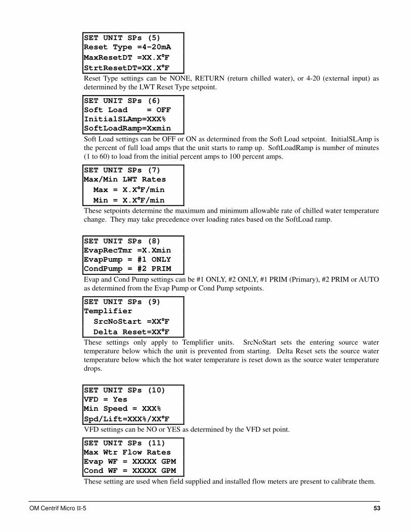
OM Centrif Micro ΙΙ-5 53
SET UNIT SPs (5)
Reset Type =4-20mA
MaxResetDT =XX.X°°°°F
StrtResetDT=XX.X°°°°F
Reset Type settings can be NONE, RETURN (return chilled water), or 4-20 (external input) as
determined by the LWT Reset Type setpoint.
SET UNIT SPs (6)
Soft Load = OFF
InitialSLAmp=XXX%
SoftLoadRamp=Xxmin
Soft Load settings can be OFF or ON as determined from the Soft Load setpoint. InitialSLAmp is
the percent of full load amps that the unit starts to ramp up. SoftLoadRamp is number of minutes
(1 to 60) to load from the initial percent amps to 100 percent amps.
SET UNIT SPs (7)
Max/Min LWT Rates
Max = X.X°°°°F/min
Min = X.X°°°°F/min
These setpoints determine the maximum and minimum allowable rate of chilled water temperature
change. They may take precedence over loading rates based on the SoftLoad ramp.
SET UNIT SPs (8)
EvapRecTmr =X.Xmin
EvapPump = #1 ONLY
CondPump = #2 PRIM
Evap and Cond Pump settings can be #1 ONLY, #2 ONLY, #1 PRIM (Primary), #2 PRIM or AUTO
as determined from the Evap Pump or Cond Pump setpoints.
SET UNIT SPs (9)
Templifier
SrcNoStart =XX°°°°F
Delta Reset=XX°°°°F
These settings only apply to Templifier units. SrcNoStart sets the entering source water
temperature below which the unit is prevented from starting. Delta Reset sets the source water
temperature below which the hot water temperature is reset down as the source water temperature
drops.
SET UNIT SPs (10)
VFD = Yes
Min Speed = XXX%
Spd/Lift=XXX%/XX°°°°F
VFD settings can be NO or YES as determined by the VFD set point.
SET UNIT SPs (11)
Max Wtr Flow Rates
Evap WF = XXXXX GPM
Cond WF = XXXXX GPM
These setting are used when field supplied and installed flow meters are present to calibrate them.
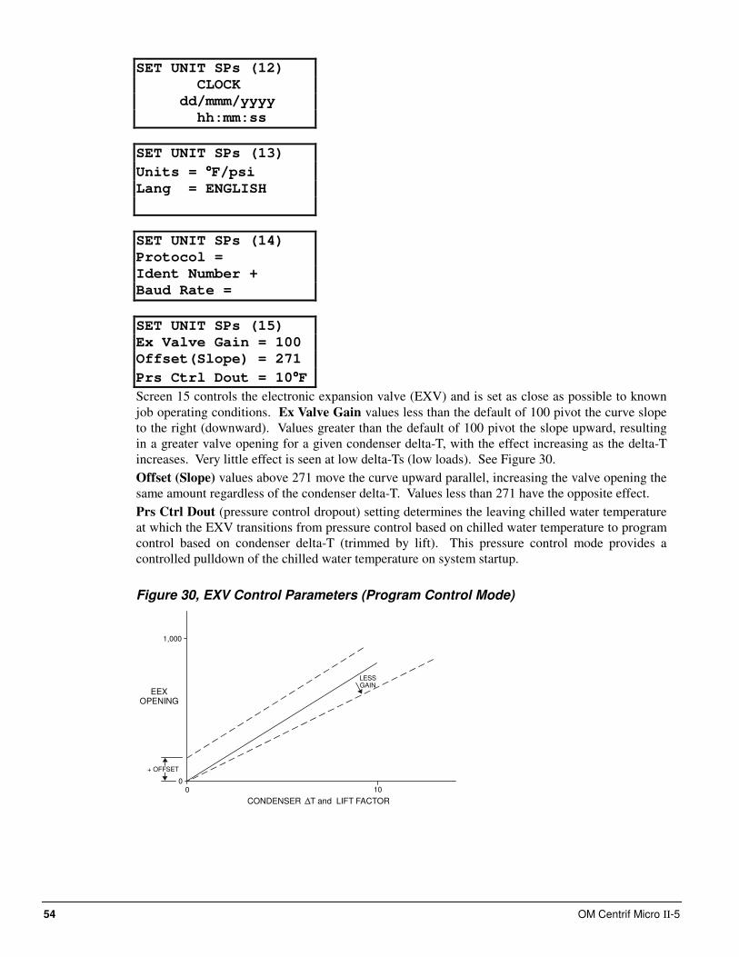
54 OM Centrif Micro ΙΙ-5
SET UNIT SPs (12)
CLOCK
dd/mmm/yyyy
hh:mm:ss
SET UNIT SPs (13)
Units = °°°°F/psi
Lang = ENGLISH
SET UNIT SPs (14)
Protocol =
Ident Number +
Baud Rate =
SET UNIT SPs (15)
Ex Valve Gain = 100
Offset(Slope) = 271
Prs Ctrl Dout = 10°°°°F
Screen 15 controls the electronic expansion valve (EXV) and is set as close as possible to known
job operating conditions. Ex Valve Gain values less than the default of 100 pivot the curve slope
to the right (downward). Values greater than the default of 100 pivot the slope upward, resulting
in a greater valve opening for a given condenser delta-T, with the effect increasing as the delta-T
increases. Very little effect is seen at low delta-Ts (low loads). See Figure 30.
Offset (Slope) values above 271 move the curve upward parallel, increasing the valve opening the
same amount regardless of the condenser delta-T. Values less than 271 have the opposite effect.
Prs Ctrl Dout (pressure control dropout) setting determines the leaving chilled water temperature
at which the EXV transitions from pressure control based on chilled water temperature to program
control based on condenser delta-T (trimmed by lift). This pressure control mode provides a
controlled pulldown of the chilled water temperature on system startup.
Figure 30, EXV Control Parameters (Program Control Mode)
LESSGAIN
1,000
EEXOPENING
+ OFFSET
00 10
CONDENSER T and LIFT FACTOR
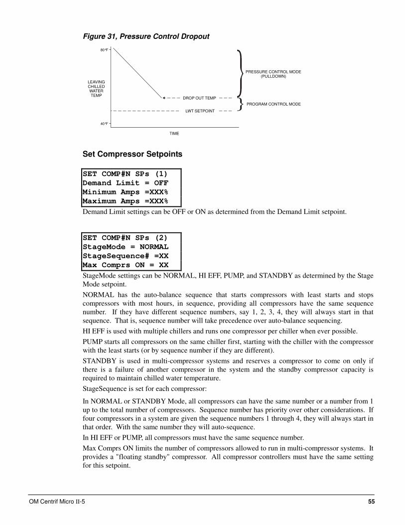
OM Centrif Micro ΙΙ-5 55
Figure 31, Pressure Control Dropout
LEAVINGCHILLEDWATERTEMP
40°F
TIME
80°F
DROP OUT TEMP
LWT SETPOINT
PRESSURE CONTROL MODE(PULLDOWN)
PROGRAM CONTROL MODE
Set Compressor Setpoints
SET COMP#N SPs (1)
Demand Limit = OFF
Minimum Amps =XXX%
Maximum Amps =XXX%
Demand Limit settings can be OFF or ON as determined from the Demand Limit setpoint.
SET COMP#N SPs (2)
StageMode = NORMAL
StageSequence# =XX
Max Comprs ON = XX
StageMode settings can be NORMAL, HI EFF, PUMP, and STANDBY as determined by the Stage
Mode setpoint.
NORMAL has the auto-balance sequence that starts compressors with least starts and stops
compressors with most hours, in sequence, providing all compressors have the same sequence
number. If they have different sequence numbers, say 1, 2, 3, 4, they will always start in that
sequence. That is, sequence number will take precedence over auto-balance sequencing.
HI EFF is used with multiple chillers and runs one compressor per chiller when ever possible.
PUMP starts all compressors on the same chiller first, starting with the chiller with the compressor
with the least starts (or by sequence number if they are different).
STANDBY is used in multi-compressor systems and reserves a compressor to come on only if
there is a failure of another compressor in the system and the standby compressor capacity is
required to maintain chilled water temperature.
StageSequence is set for each compressor:
In NORMAL or STANDBY Mode, all compressors can have the same number or a number from 1
up to the total number of compressors. Sequence number has priority over other considerations. If
four compressors in a system are given the sequence numbers 1 through 4, they will always start in
that order. With the same number they will auto-sequence.
In HI EFF or PUMP, all compressors must have the same sequence number.
Max Comprs ON limits the number of compressors allowed to run in multi-compressor systems. It
provides a "floating standby" compressor. All compressor controllers must have the same setting
for this setpoint.
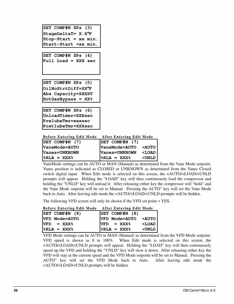
56 OM Centrif Micro ΙΙ-5
SET COMP#N SPs (3)
StageDeltaT= X.X°°°°F
Stop-Start = xx min.
Start-Start =xx min.
SET COMP#N SPs (4)
Full Load = XXX sec
SET COMP#N SPs (5)
OilNoStrtDiff=XX°°°°F
Abs Capacity=XXXXT
HotGasBypass = XX%
SET COMP#N SPs (6)
UnloadTimer=XXXsec
PrelubeTmr=xxxsec
PostlubeTmr=XXXsec
Before Entering Edit Mode After Entering Edit Mode
SET COMP#N (7) SET COMP#N (7)
VaneMode=AUTO VaneMode=AUTO <AUTO
Vanes=UNKNOWN Vanes=UNKNOWN <LOAD
%RLA = XXX% %RLA = XXX% <UNLD
VaneMode settings can be AUTO or MAN (Manual) as determined from the Vane Mode setpoint.
Vanes position is indicated as CLOSED or UNKNOWN as determined from the Vanes Closed
switch digital input. When Edit mode is selected on this screen, the <AUTO/<LOAD/<UNLD
prompts will appear. Holding the “LOAD” key will then continuously load the compressor and
holding the “UNLD“ key will unload it. After releasing either key the compressor will “hold” and
the Vane Mode setpoint will be set to Manual. Pressing the AUTO” key will set the Vane Mode
back to Auto. After leaving edit mode the <AUTO/<LOAD/<UNLD prompts will be hidden.
The following VFD screen will only be shown if the VFD set point = YES.
Before Entering Edit Mode After Entering Edit Mode
SET COMP#N (8) SET COMP#N (8)
VFD Mode=AUTO VFD Mode=AUTO <AUTO
VFD = XXX% VFD = XXX% <LOAD
%RLA = XXX% %RLA = XXX% <UNLD
VFD Mode settings can be AUTO or MAN (Manual) as determined from the VFD Mode setpoint.
VFD speed is shown as 0 to 100%. When Edit mode is selected on this screen, the
<AUTO/<LOAD/<UNLD prompts will appear. Holding the “LOAD” key will then continuously
speed up the VFD and holding the “UNLD“ key will slow it down. After releasing either key the
VFD will stay at the current speed and the VFD Mode setpoint will be set to Manual. Pressing the
AUTO” key will set the VFD Mode back to Auto. After leaving edit mode the
<AUTO/<LOAD/<UNLD prompts will be hidden.
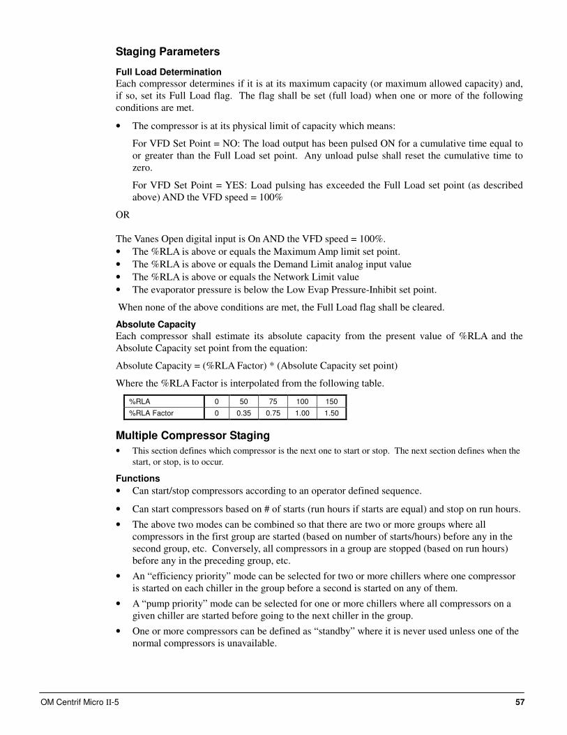
OM Centrif Micro ΙΙ-5 57
Staging Parameters
Full Load Determination
Each compressor determines if it is at its maximum capacity (or maximum allowed capacity) and,
if so, set its Full Load flag. The flag shall be set (full load) when one or more of the following
conditions are met.
• The compressor is at its physical limit of capacity which means:
For VFD Set Point = NO: The load output has been pulsed ON for a cumulative time equal to
or greater than the Full Load set point. Any unload pulse shall reset the cumulative time to
zero.
For VFD Set Point = YES: Load pulsing has exceeded the Full Load set point (as described
above) AND the VFD speed = 100%
OR
The Vanes Open digital input is On AND the VFD speed = 100%.
• The %RLA is above or equals the Maximum Amp limit set point.
• The %RLA is above or equals the Demand Limit analog input value
• The %RLA is above or equals the Network Limit value
• The evaporator pressure is below the Low Evap Pressure-Inhibit set point.
When none of the above conditions are met, the Full Load flag shall be cleared.
Absolute Capacity
Each compressor shall estimate its absolute capacity from the present value of %RLA and the
Absolute Capacity set point from the equation:
Absolute Capacity = (%RLA Factor) * (Absolute Capacity set point)
Where the %RLA Factor is interpolated from the following table.
%RLA 0 50 75 100 150
%RLA Factor 0 0.35 0.75 1.00 1.50
Multiple Compressor Staging
• This section defines which compressor is the next one to start or stop. The next section defines when the
start, or stop, is to occur.
Functions
• Can start/stop compressors according to an operator defined sequence.
• Can start compressors based on # of starts (run hours if starts are equal) and stop on run hours.
• The above two modes can be combined so that there are two or more groups where all
compressors in the first group are started (based on number of starts/hours) before any in the
second group, etc. Conversely, all compressors in a group are stopped (based on run hours)
before any in the preceding group, etc.
• An “efficiency priority” mode can be selected for two or more chillers where one compressor
is started on each chiller in the group before a second is started on any of them.
• A “pump priority” mode can be selected for one or more chillers where all compressors on a
given chiller are started before going to the next chiller in the group.
• One or more compressors can be defined as “standby” where it is never used unless one of the
normal compressors is unavailable.
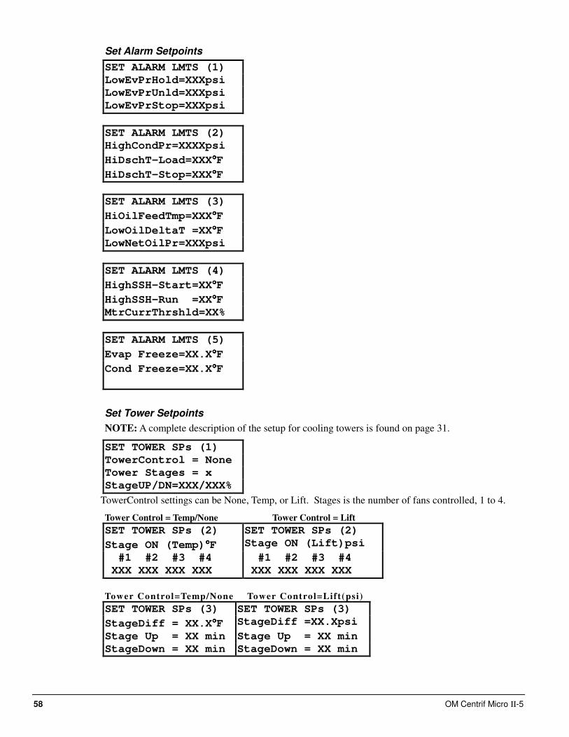
58 OM Centrif Micro ΙΙ-5
Set Alarm Setpoints
SET ALARM LMTS (1)
LowEvPrHold=XXXpsi
LowEvPrUnld=XXXpsi
LowEvPrStop=XXXpsi
SET ALARM LMTS (2)
HighCondPr=XXXXpsi
HiDschT-Load=XXX°°°°F
HiDschT-Stop=XXX°°°°F
SET ALARM LMTS (3)
HiOilFeedTmp=XXX°°°°F
LowOilDeltaT =XX°°°°F
LowNetOilPr=XXXpsi
SET ALARM LMTS (4)
HighSSH-Start=XX°°°°F
HighSSH-Run =XX°°°°F
MtrCurrThrshld=XX%
SET ALARM LMTS (5)
Evap Freeze=XX.X°°°°F
Cond Freeze=XX.X°°°°F
Set Tower Setpoints
NOTE: A complete description of the setup for cooling towers is found on page 31.
SET TOWER SPs (1)
TowerControl = None
Tower Stages = x
StageUP/DN=XXX/XXX%
TowerControl settings can be None, Temp, or Lift. Stages is the number of fans controlled, 1 to 4.
Tower Control = Temp/None Tower Control = Lift
SET TOWER SPs (2) SET TOWER SPs (2)
Stage ON (Temp)°°°°F Stage ON (Lift)psi
#1 #2 #3 #4 #1 #2 #3 #4
XXX XXX XXX XXX XXX XXX XXX XXX
Tower Control=Temp/None Tower Control=Lift(psi)
SET TOWER SPs (3) SET TOWER SPs (3)
StageDiff = XX.X°°°°F StageDiff =XX.Xpsi
Stage Up = XX min Stage Up = XX min
StageDown = XX min StageDown = XX min
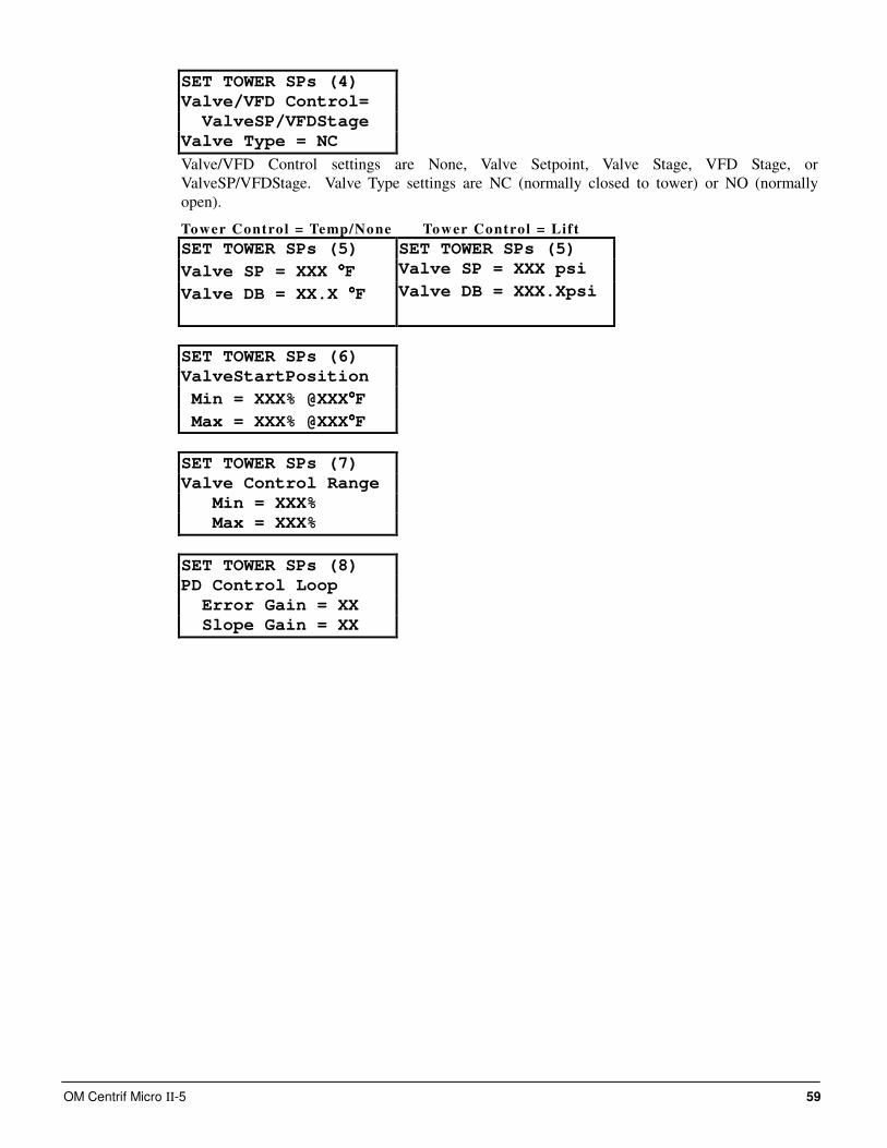
OM Centrif Micro ΙΙ-5 59
SET TOWER SPs (4)
Valve/VFD Control=
ValveSP/VFDStage
Valve Type = NC
Valve/VFD Control settings are None, Valve Setpoint, Valve Stage, VFD Stage, or
ValveSP/VFDStage. Valve Type settings are NC (normally closed to tower) or NO (normally
open).
Tower Control = Temp/None Tower Control = Lift
SET TOWER SPs (5) SET TOWER SPs (5)
Valve SP = XXX °°°°F Valve SP = XXX psi
Valve DB = XX.X °°°°F Valve DB = XXX.Xpsi
SET TOWER SPs (6)
ValveStartPosition
Min = XXX% @XXX°°°°F
Max = XXX% @XXX°°°°F
SET TOWER SPs (7)
Valve Control Range
Min = XXX%
Max = XXX%
SET TOWER SPs (8)
PD Control Loop
Error Gain = XX
Slope Gain = XX
60 OM Centrif Micro ΙΙ-5
Alarms When an alarm occurs, the alarm type, limit value (if any), date, and time are stored in the active
alarm buffer corresponding to that alarm (viewed on the Active Alarm screen) and also in the
alarm history buffer (viewed on the Alarm History screen). The active alarm buffers hold a record
of the last occurrence of each alarm and whether or not it has been cleared. The alarm can be
cleared by pressing the Edit key. A separate buffer is available for each alarm (High Cond
Pressure, Evaporator Freeze Protect, etc.). The alarm history buffer holds a chronological account
of the last 50 alarms of any type.
Security
Entering on the Unit Controller
Two four-digit passwords provide OPERATOR and MANAGER levels of access to changeable
parameters. Either password can be entered using the SET PASSWORD screen which can be
accessed either through the SET OTHER menu or by simply pressing the ENTER key while on
one of the SET screens. The password can then be entered by
1. Press the ENTER key.
2. Move to each number space to be changed with the right or left button.
3. Enter the correct value by scrolling with the UP and DOWN arrow keys. The password is
right justified on the controller screen. The operator password would look like 00100, the
manager password would be 02001.
4. Press ENTER again to enter the password
Once the correct password has been entered, the previously selected screen will reappear. Once a
password has been entered, it will remain valid for 15 minutes after the last key-press. Parameters
and screens that require the MANAGER password will not be displayed unless the MANAGER
password is active.
Entering on the OITS
When a password is required, the touch screen will automatically go to the screen keyboard.
Numbers are left justified and the operator password would be 100 (appearing as *** in the
window). See page 24 for further information.
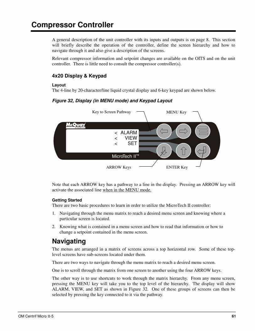
OM Centrif Micro ΙΙ-5 61
Compressor Controller
A general description of the unit controller with its inputs and outputs is on page 8. This section
will briefly describe the operation of the controller, define the screen hierarchy and how to
navigate through it and also give a description of the screens.
Relevant compressor information and setpoint changes are available on the OITS and on the unit
controller. There is little need to consult the compressor controller(s).
4x20 Display & Keypad
Layout
The 4-line by 20-character/line liquid crystal display and 6-key keypad are shown below.
Figure 32, Display (in MENU mode) and Keypad Layout
Air Conditioning
ALARMVIEW
SET
<<<
Note that each ARROW key has a pathway to a line in the display. Pressing an ARROW key will
activate the associated line when in the MENU mode.
Getting Started
There are two basic procedures to learn in order to utilize the MicroTech II controller:
1. Navigating through the menu matrix to reach a desired menu screen and knowing where a
particular screen is located.
2. Knowing what is contained in a menu screen and how to read that information or how to
change a setpoint contained in the menu screen.
Navigating The menus are arranged in a matrix of screens across a top horizontal row. Some of these top-
level screens have sub-screens located under them.
There are two ways to navigate through the menu matrix to reach a desired menu screen.
One is to scroll through the matrix from one screen to another using the four ARROW keys.
The other way is to use shortcuts to work through the matrix hierarchy. From any menu screen,
pressing the MENU key will take you to the top level of the hierarchy. The display will show
ALARM, VIEW, and SET as shown in Figure 32. One of these groups of screens can then be
selected by pressing the key connected to it via the pathway.
ENTER Key
MENU Key
ARROW Keys
Key to Screen Pathway
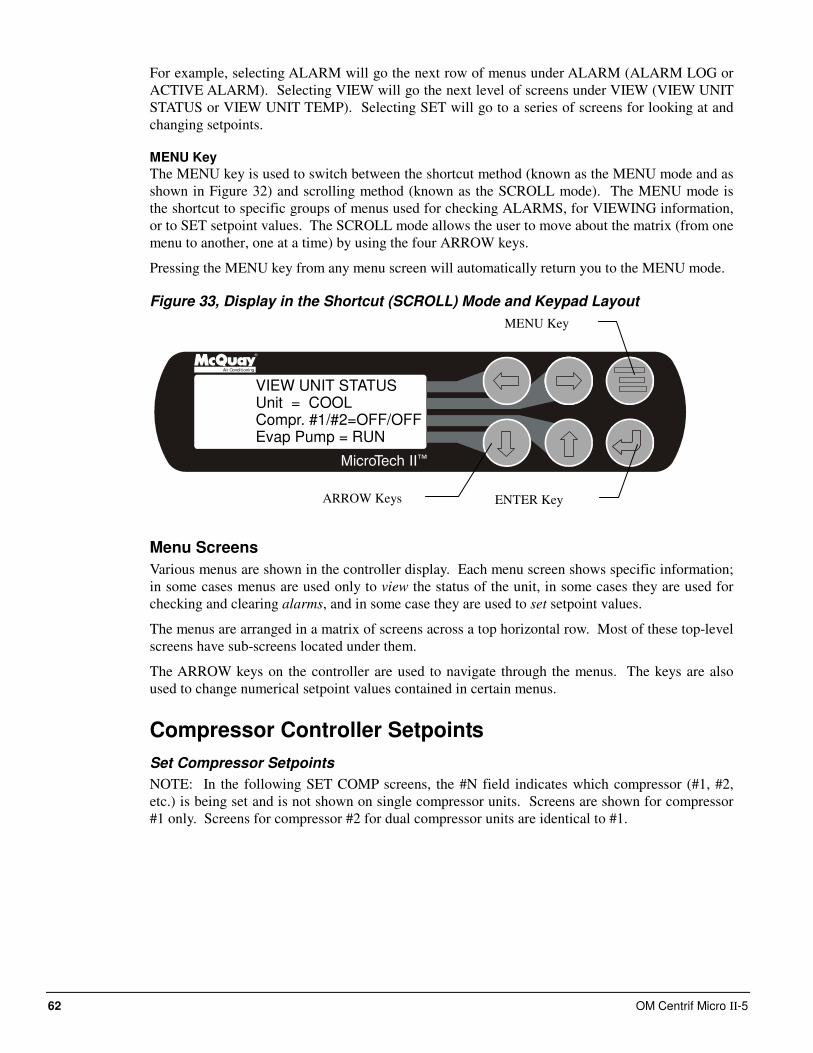
62 OM Centrif Micro ΙΙ-5
For example, selecting ALARM will go the next row of menus under ALARM (ALARM LOG or
ACTIVE ALARM). Selecting VIEW will go the next level of screens under VIEW (VIEW UNIT
STATUS or VIEW UNIT TEMP). Selecting SET will go to a series of screens for looking at and
changing setpoints.
MENU Key
The MENU key is used to switch between the shortcut method (known as the MENU mode and as
shown in Figure 32) and scrolling method (known as the SCROLL mode). The MENU mode is
the shortcut to specific groups of menus used for checking ALARMS, for VIEWING information,
or to SET setpoint values. The SCROLL mode allows the user to move about the matrix (from one
menu to another, one at a time) by using the four ARROW keys.
Pressing the MENU key from any menu screen will automatically return you to the MENU mode.
Figure 33, Display in the Shortcut (SCROLL) Mode and Keypad Layout
Air Conditioning
VIEW UNIT STATUSUnit = COOLCompr. #1/#2=OFF/OFFEvap Pump = RUN
Menu Screens
Various menus are shown in the controller display. Each menu screen shows specific information;
in some cases menus are used only to view the status of the unit, in some cases they are used for
checking and clearing alarms, and in some case they are used to set setpoint values.
The menus are arranged in a matrix of screens across a top horizontal row. Most of these top-level
screens have sub-screens located under them.
The ARROW keys on the controller are used to navigate through the menus. The keys are also
used to change numerical setpoint values contained in certain menus.
Compressor Controller Setpoints
Set Compressor Setpoints
NOTE: In the following SET COMP screens, the #N field indicates which compressor (#1, #2,
etc.) is being set and is not shown on single compressor units. Screens are shown for compressor
#1 only. Screens for compressor #2 for dual compressor units are identical to #1.
MENU Key
ENTER Key ARROW Keys
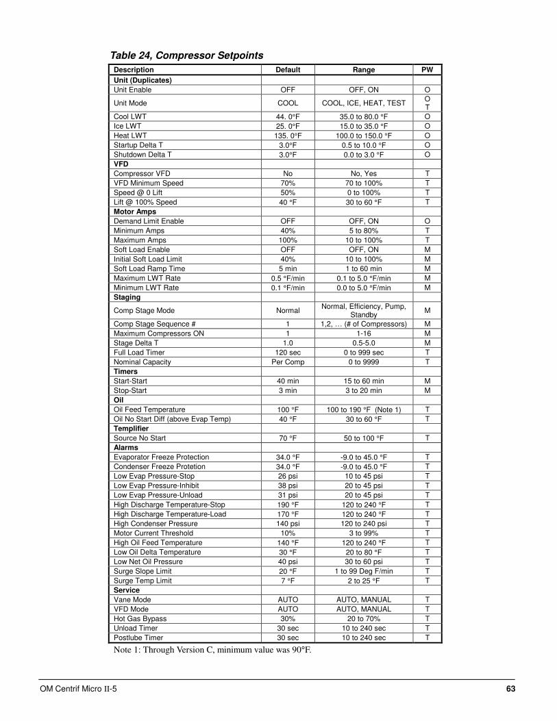
OM Centrif Micro ΙΙ-5 63
Table 24, Compressor Setpoints
Description Default Range PW
Unit (Duplicates)
Unit Enable OFF OFF, ON O
Unit Mode COOL COOL, ICE, HEAT, TEST O T
Cool LWT 44. 0°F 35.0 to 80.0 °F O
Ice LWT 25. 0°F 15.0 to 35.0 °F O
Heat LWT 135. 0°F 100.0 to 150.0 °F O
Startup Delta T 3.0°F 0.5 to 10.0 °F O
Shutdown Delta T 3.0°F 0.0 to 3.0 °F O
VFD
Compressor VFD No No, Yes T
VFD Minimum Speed 70% 70 to 100% T
Speed @ 0 Lift 50% 0 to 100% T
Lift @ 100% Speed 40 °F 30 to 60 °F T
Motor Amps
Demand Limit Enable OFF OFF, ON O
Minimum Amps 40% 5 to 80% T
Maximum Amps 100% 10 to 100% T
Soft Load Enable OFF OFF, ON M
Initial Soft Load Limit 40% 10 to 100% M
Soft Load Ramp Time 5 min 1 to 60 min M
Maximum LWT Rate 0.5 °F/min 0.1 to 5.0 °F/min M
Minimum LWT Rate 0.1 °F/min 0.0 to 5.0 °F/min M
Staging
Comp Stage Mode Normal Normal, Efficiency, Pump,
Standby M
Comp Stage Sequence # 1 1,2, … (# of Compressors) M
Maximum Compressors ON 1 1-16 M
Stage Delta T 1.0 0.5-5.0 M
Full Load Timer 120 sec 0 to 999 sec T
Nominal Capacity Per Comp 0 to 9999 T
Timers
Start-Start 40 min 15 to 60 min M
Stop-Start 3 min 3 to 20 min M
Oil
Oil Feed Temperature 100 °F 100 to 190 °F (Note 1) T
Oil No Start Diff (above Evap Temp) 40 °F 30 to 60 °F T
Templifier
Source No Start 70 °F 50 to 100 °F T
Alarms
Evaporator Freeze Protection 34.0 °F -9.0 to 45.0 °F T
Condenser Freeze Protetion 34.0 °F -9.0 to 45.0 °F T
Low Evap Pressure-Stop 26 psi 10 to 45 psi T
Low Evap Pressure-Inhibit 38 psi 20 to 45 psi T
Low Evap Pressure-Unload 31 psi 20 to 45 psi T
High Discharge Temperature-Stop 190 °F 120 to 240 °F T
High Discharge Temperature-Load 170 °F 120 to 240 °F T
High Condenser Pressure 140 psi 120 to 240 psi T
Motor Current Threshold 10% 3 to 99% T
High Oil Feed Temperature 140 °F 120 to 240 °F T
Low Oil Delta Temperature 30 °F 20 to 80 °F T
Low Net Oil Pressure 40 psi 30 to 60 psi T
Surge Slope Limit 20 °F 1 to 99 Deg F/min T
Surge Temp Limit 7 °F 2 to 25 °F T
Service
Vane Mode AUTO AUTO, MANUAL T
VFD Mode AUTO AUTO, MANUAL T
Hot Gas Bypass 30% 20 to 70% T
Unload Timer 30 sec 10 to 240 sec T
Postlube Timer 30 sec 10 to 240 sec T
Note 1: Through Version C, minimum value was 90°F.
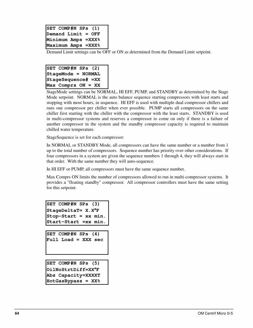
64 OM Centrif Micro ΙΙ-5
SET COMP#N SPs (1)
Demand Limit = OFF
Minimum Amps =XXX%
Maximum Amps =XXX%
Demand Limit settings can be OFF or ON as determined from the Demand Limit setpoint.
SET COMP#N SPs (2)
StageMode = NORMAL
StageSequence# =XX
Max Comprs ON = XX
StageMode settings can be NORMAL, HI EFF, PUMP, and STANDBY as determined by the Stage
Mode setpoint. NORMAL is the auto balance sequence starting compressors with least starts and
stopping with most hours, in sequence. HI EFF is used with multiple dual compressor chillers and
runs one compressor per chiller when ever possible. PUMP starts all compressors on the same
chiller first starting with the chiller with the compressor with the least starts. STANDBY is used
in multi-compressor systems and reserves a compressor to come on only if there is a failure of
another compressor in the system and the standby compressor capacity is required to maintain
chilled water temperature.
StageSequence is set for each compressor:
In NORMAL or STANDBY Mode, all compressors can have the same number or a number from 1
up to the total number of compressors. Sequence number has priority over other considerations. If
four compressors in a system are given the sequence numbers 1 through 4, they will always start in
that order. With the same number they will auto-sequence.
In HI EFF or PUMP, all compressors must have the same sequence number.
Max Comprs ON limits the number of compressors allowed to run in multi-compressor systems. It
provides a "floating standby" compressor. All compressor controllers must have the same setting
for this setpoint.
SET COMP#N SPs (3)
StageDeltaT= X.X°°°°F
Stop-Start = xx min.
Start-Start =xx min.
SET COMP#N SPs (4)
Full Load = XXX sec
SET COMP#N SPs (5)
OilNoStrtDiff=XX°°°°F
Abs Capacity=XXXXT
HotGasBypass = XX%
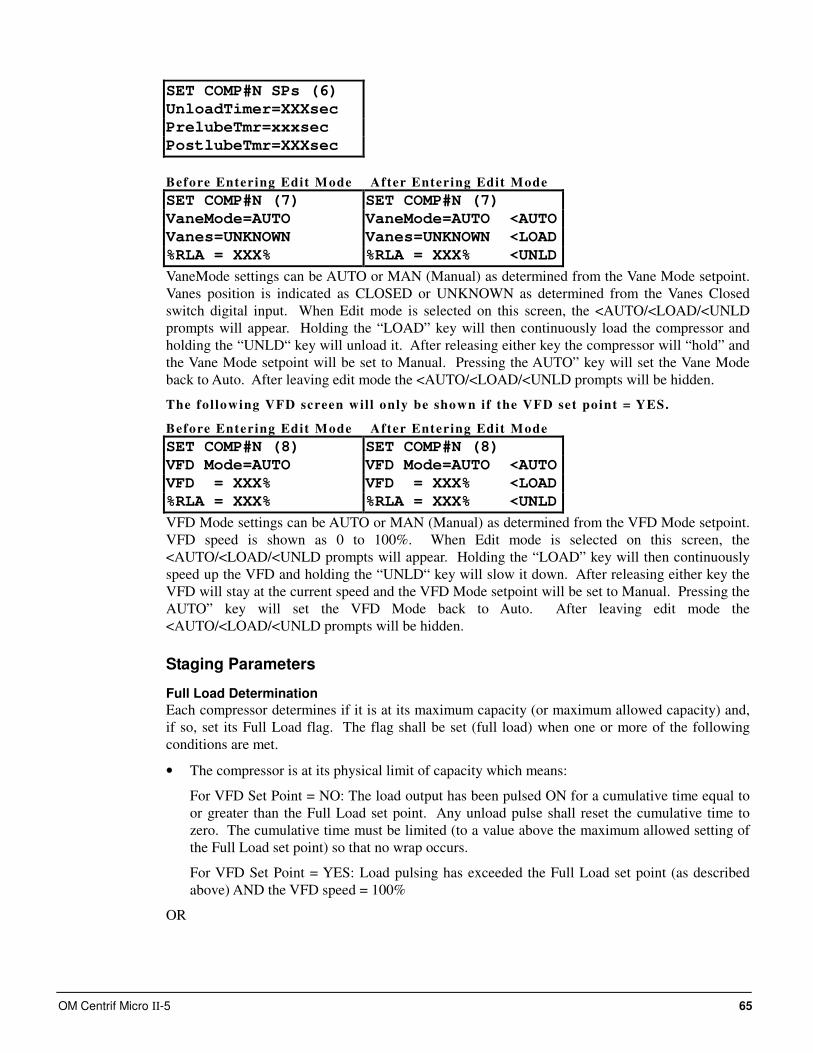
OM Centrif Micro ΙΙ-5 65
SET COMP#N SPs (6)
UnloadTimer=XXXsec
PrelubeTmr=xxxsec
PostlubeTmr=XXXsec
Before Entering Edit Mode After Entering Edit Mode
SET COMP#N (7) SET COMP#N (7)
VaneMode=AUTO VaneMode=AUTO <AUTO
Vanes=UNKNOWN Vanes=UNKNOWN <LOAD
%RLA = XXX% %RLA = XXX% <UNLD
VaneMode settings can be AUTO or MAN (Manual) as determined from the Vane Mode setpoint.
Vanes position is indicated as CLOSED or UNKNOWN as determined from the Vanes Closed
switch digital input. When Edit mode is selected on this screen, the <AUTO/<LOAD/<UNLD
prompts will appear. Holding the “LOAD” key will then continuously load the compressor and
holding the “UNLD“ key will unload it. After releasing either key the compressor will “hold” and
the Vane Mode setpoint will be set to Manual. Pressing the AUTO” key will set the Vane Mode
back to Auto. After leaving edit mode the <AUTO/<LOAD/<UNLD prompts will be hidden.
The fol lowing VFD screen wil l only be shown if the VFD set point = YES.
Before Entering Edit Mode After Entering Edit Mode
SET COMP#N (8) SET COMP#N (8)
VFD Mode=AUTO VFD Mode=AUTO <AUTO
VFD = XXX% VFD = XXX% <LOAD
%RLA = XXX% %RLA = XXX% <UNLD
VFD Mode settings can be AUTO or MAN (Manual) as determined from the VFD Mode setpoint.
VFD speed is shown as 0 to 100%. When Edit mode is selected on this screen, the
<AUTO/<LOAD/<UNLD prompts will appear. Holding the “LOAD” key will then continuously
speed up the VFD and holding the “UNLD“ key will slow it down. After releasing either key the
VFD will stay at the current speed and the VFD Mode setpoint will be set to Manual. Pressing the
AUTO” key will set the VFD Mode back to Auto. After leaving edit mode the
<AUTO/<LOAD/<UNLD prompts will be hidden.
Staging Parameters
Full Load Determination
Each compressor determines if it is at its maximum capacity (or maximum allowed capacity) and,
if so, set its Full Load flag. The flag shall be set (full load) when one or more of the following
conditions are met.
• The compressor is at its physical limit of capacity which means:
For VFD Set Point = NO: The load output has been pulsed ON for a cumulative time equal to
or greater than the Full Load set point. Any unload pulse shall reset the cumulative time to
zero. The cumulative time must be limited (to a value above the maximum allowed setting of
the Full Load set point) so that no wrap occurs.
For VFD Set Point = YES: Load pulsing has exceeded the Full Load set point (as described
above) AND the VFD speed = 100%
OR
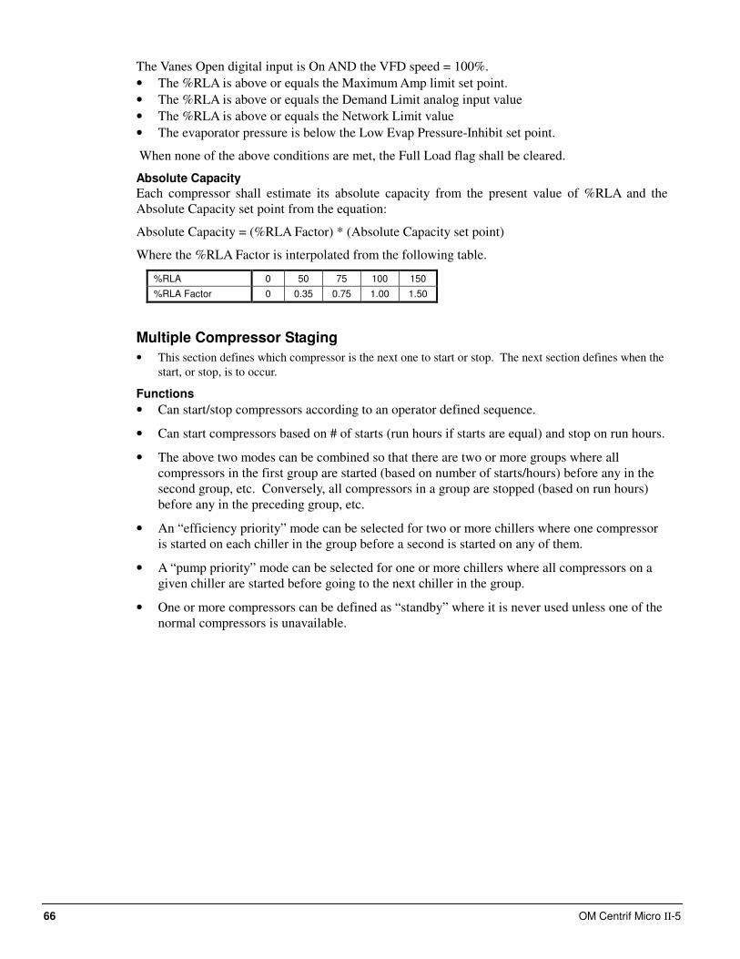
66 OM Centrif Micro ΙΙ-5
The Vanes Open digital input is On AND the VFD speed = 100%.
• The %RLA is above or equals the Maximum Amp limit set point.
• The %RLA is above or equals the Demand Limit analog input value
• The %RLA is above or equals the Network Limit value
• The evaporator pressure is below the Low Evap Pressure-Inhibit set point.
When none of the above conditions are met, the Full Load flag shall be cleared.
Absolute Capacity
Each compressor shall estimate its absolute capacity from the present value of %RLA and the
Absolute Capacity set point from the equation:
Absolute Capacity = (%RLA Factor) * (Absolute Capacity set point)
Where the %RLA Factor is interpolated from the following table.
%RLA 0 50 75 100 150
%RLA Factor 0 0.35 0.75 1.00 1.50
Multiple Compressor Staging
• This section defines which compressor is the next one to start or stop. The next section defines when the
start, or stop, is to occur.
Functions
• Can start/stop compressors according to an operator defined sequence.
• Can start compressors based on # of starts (run hours if starts are equal) and stop on run hours.
• The above two modes can be combined so that there are two or more groups where all
compressors in the first group are started (based on number of starts/hours) before any in the
second group, etc. Conversely, all compressors in a group are stopped (based on run hours)
before any in the preceding group, etc.
• An “efficiency priority” mode can be selected for two or more chillers where one compressor
is started on each chiller in the group before a second is started on any of them.
• A “pump priority” mode can be selected for one or more chillers where all compressors on a
given chiller are started before going to the next chiller in the group.
• One or more compressors can be defined as “standby” where it is never used unless one of the
normal compressors is unavailable.
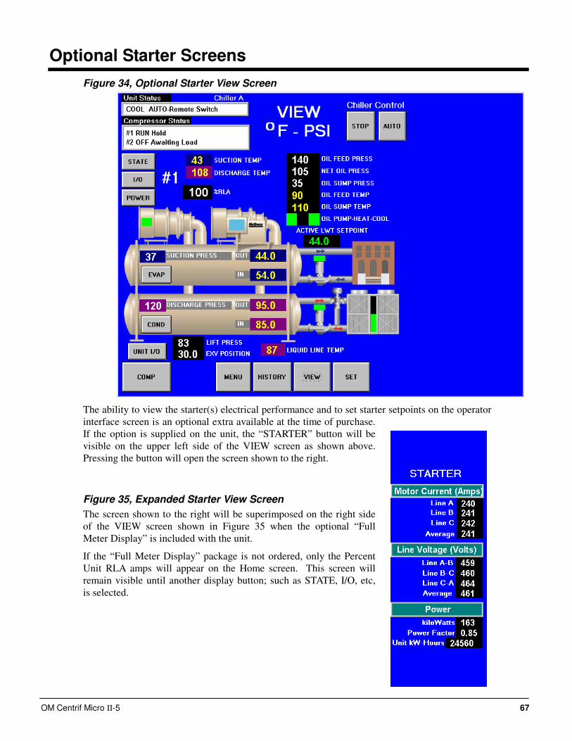
OM Centrif Micro ΙΙ-5 67
Optional Starter Screens
Figure 34, Optional Starter View Screen
The ability to view the starter(s) electrical performance and to set starter setpoints on the operator
interface screen is an optional extra available at the time of purchase.
If the option is supplied on the unit, the “STARTER” button will be
visible on the upper left side of the VIEW screen as shown above.
Pressing the button will open the screen shown to the right.
Figure 35, Expanded Starter View Screen
The screen shown to the right will be superimposed on the right side
of the VIEW screen shown in Figure 35 when the optional “Full
Meter Display” is included with the unit.
If the “Full Meter Display” package is not ordered, only the Percent
Unit RLA amps will appear on the Home screen. This screen will
remain visible until another display button; such as STATE, I/O, etc,
is selected.
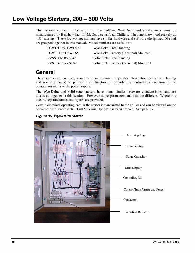
68 OM Centrif Micro ΙΙ-5
Low Voltage Starters, 200 – 600 Volts
This section contains information on low voltage, Wye-Delta and solid-state starters as
manufactured by Benshaw Inc. for McQuay centrifugal Chillers. They are known collectively as
“D3” starters. These low voltage starters have similar hardware and software (designated D3) and
are grouped together in this manual. Model numbers are as follows:
D3WD11 to D3WD2K Wye-Delta, Free Standing
D3WT11 to D3WT65 Wye-Delta, Factory (Terminal) Mounted
RVSS14 to RVSS4K Solid State, Free Standing
RVST14 to RVST82 Solid State, Factory (Terminal) Mounted
General These starters are completely automatic and require no operator intervention (other than clearing
and resetting faults) to perform their function of providing a controlled connection of the
compressor motor to the power supply.
The Wye-Delta and solid-state starters have many similar software characteristics and are
discussed together in this section. However, some parameters and data are different. Where this
occurs, separate tables and figures are provided.
Certain electrical operating data in the starter is transmitted to the chiller and can be viewed on the
operator touch screen if the “Full Metering Option” has been ordered. See page 67.
Figure 36, Wye-Delta Starter
LED Display
Incoming Lugs
Surge Capacitor
Terminal Strip
Controller, D3
Control Transformer and Fuses
Contactors
Transition Resistors
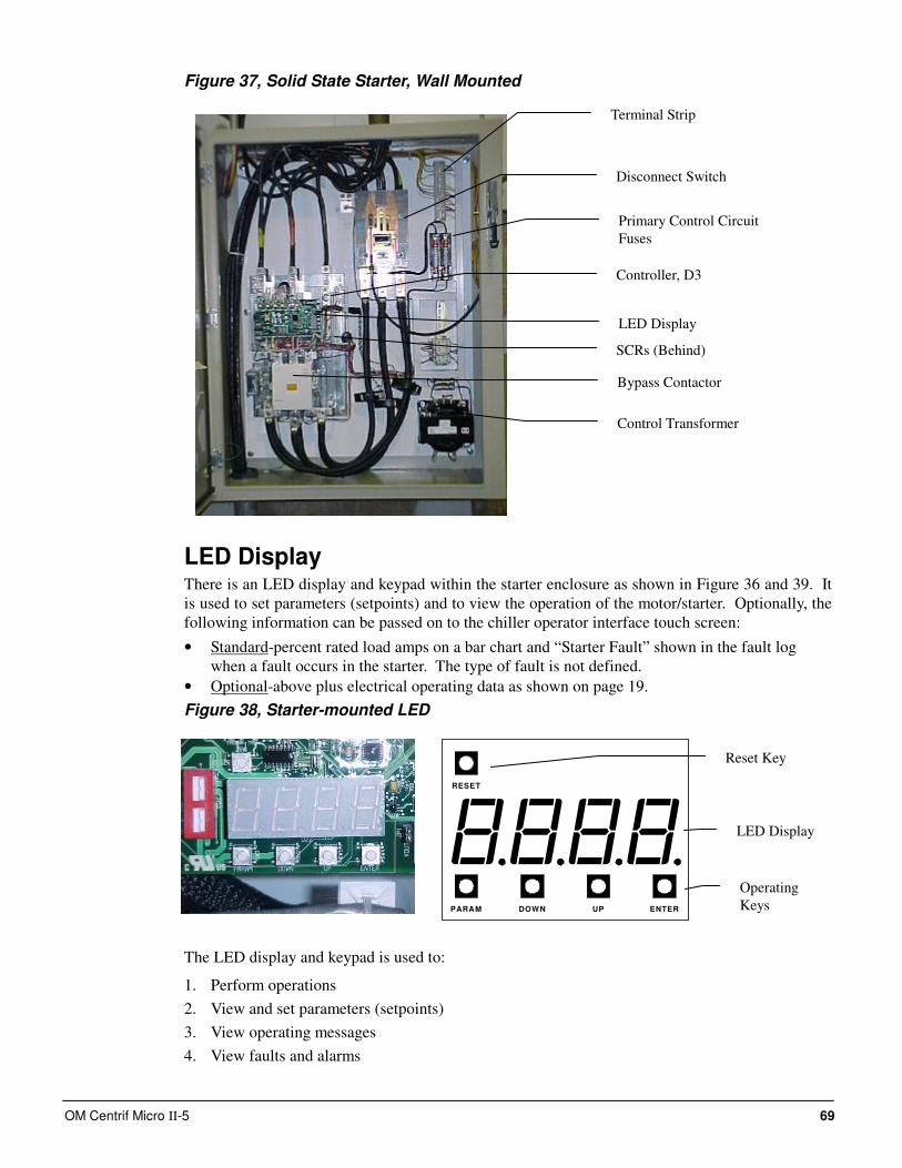
OM Centrif Micro ΙΙ-5 69
Figure 37, Solid State Starter, Wall Mounted
LED Display There is an LED display and keypad within the starter enclosure as shown in Figure 36 and 39. It
is used to set parameters (setpoints) and to view the operation of the motor/starter. Optionally, the
following information can be passed on to the chiller operator interface touch screen:
• Standard-percent rated load amps on a bar chart and “Starter Fault” shown in the fault log
when a fault occurs in the starter. The type of fault is not defined.
• Optional-above plus electrical operating data as shown on page 19.
Figure 38, Starter-mounted LED
The LED display and keypad is used to:
1. Perform operations
2. View and set parameters (setpoints)
3. View operating messages
4. View faults and alarms
PARAM DOWN UP ENTER
RESET
Terminal Strip
Disconnect Switch
Primary Control Circuit
Fuses
Control Transformer
SCRs (Behind)
Controller, D3
Bypass Contactor
LED Display
Operating
Keys
Reset Key
LED Display
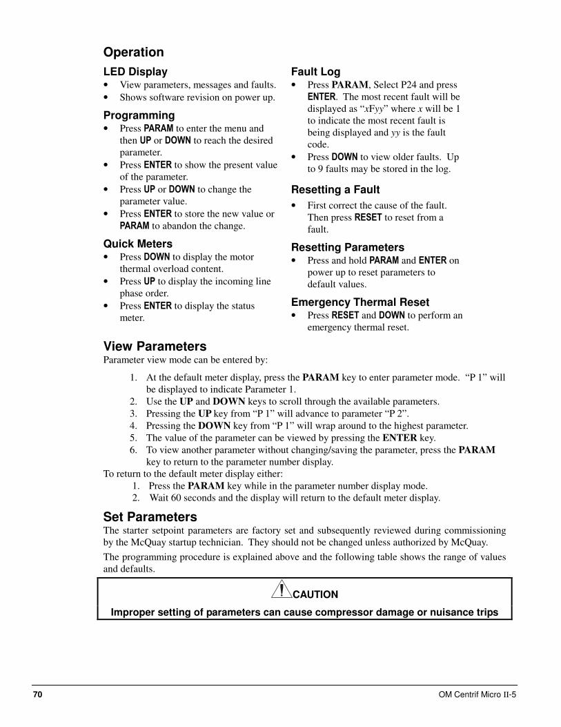
70 OM Centrif Micro ΙΙ-5
Operation
LED Display • View parameters, messages and faults.
• Shows software revision on power up.
Programming • Press PARAM to enter the menu and
then UP or DOWN to reach the desired
parameter.
• Press ENTER to show the present value
of the parameter.
• Press UP or DOWN to change the
parameter value.
• Press ENTER to store the new value or
PARAM to abandon the change.
Quick Meters • Press DOWN to display the motor
thermal overload content.
• Press UP to display the incoming line
phase order.
• Press ENTER to display the status
meter.
Fault Log • Press PARAM, Select P24 and press
ENTER. The most recent fault will be
displayed as “xFyy” where x will be 1
to indicate the most recent fault is
being displayed and yy is the fault
code.
• Press DOWN to view older faults. Up
to 9 faults may be stored in the log.
Resetting a Fault
• First correct the cause of the fault.
Then press RESET to reset from a
fault.
Resetting Parameters • Press and hold PARAM and ENTER on
power up to reset parameters to
default values.
Emergency Thermal Reset • Press RESET and DOWN to perform an
emergency thermal reset.
View Parameters Parameter view mode can be entered by:
1. At the default meter display, press the PARAM key to enter parameter mode. “P 1” will
be displayed to indicate Parameter 1.
2. Use the UP and DOWN keys to scroll through the available parameters.
3. Pressing the UP key from “P 1” will advance to parameter “P 2”.
4. Pressing the DOWN key from “P 1” will wrap around to the highest parameter.
5. The value of the parameter can be viewed by pressing the ENTER key.
6. To view another parameter without changing/saving the parameter, press the PARAM
key to return to the parameter number display.
To return to the default meter display either:
1. Press the PARAM key while in the parameter number display mode.
2. Wait 60 seconds and the display will return to the default meter display.
Set Parameters The starter setpoint parameters are factory set and subsequently reviewed during commissioning
by the McQuay startup technician. They should not be changed unless authorized by McQuay.
The programming procedure is explained above and the following table shows the range of values
and defaults.
CAUTION
Improper setting of parameters can cause compressor damage or nuisance trips
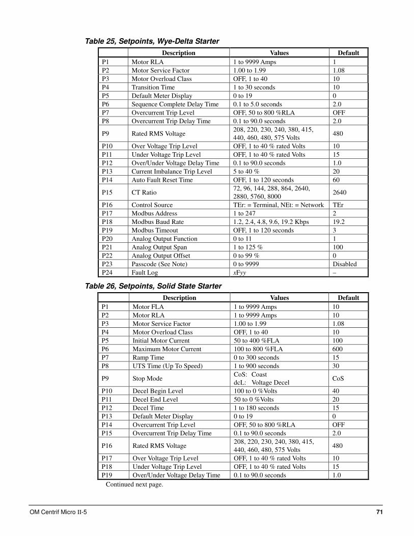
OM Centrif Micro ΙΙ-5 71
Table 25, Setpoints, Wye-Delta Starter
Description Values Default
P1 Motor RLA 1 to 9999 Amps 1
P2 Motor Service Factor 1.00 to 1.99 1.08
P3 Motor Overload Class OFF, 1 to 40 10
P4 Transition Time 1 to 30 seconds 10
P5 Default Meter Display 0 to 19 0
P6 Sequence Complete Delay Time 0.1 to 5.0 seconds 2.0
P7 Overcurrent Trip Level OFF, 50 to 800 %RLA OFF
P8 Overcurrent Trip Delay Time 0.1 to 90.0 seconds 2.0
P9 Rated RMS Voltage 208, 220, 230, 240, 380, 415,
440, 460, 480, 575 Volts 480
P10 Over Voltage Trip Level OFF, 1 to 40 % rated Volts 10
P11 Under Voltage Trip Level OFF, 1 to 40 % rated Volts 15
P12 Over/Under Voltage Delay Time 0.1 to 90.0 seconds 1.0
P13 Current Imbalance Trip Level 5 to 40 % 20
P14 Auto Fault Reset Time OFF, 1 to 120 seconds 60
P15 CT Ratio 72, 96, 144, 288, 864, 2640,
2880, 5760, 8000 2640
P16 Control Source TEr: = Terminal, NEt: = Network TEr
P17 Modbus Address 1 to 247 2
P18 Modbus Baud Rate 1.2, 2.4, 4.8, 9.6, 19.2 Kbps 19.2
P19 Modbus Timeout OFF, 1 to 120 seconds 3
P20 Analog Output Function 0 to 11 1
P21 Analog Output Span 1 to 125 % 100
P22 Analog Output Offset 0 to 99 % 0
P23 Passcode (See Note) 0 to 9999 Disabled
P24 Fault Log xFyy –
Table 26, Setpoints, Solid State Starter
Description Values Default
P1 Motor FLA 1 to 9999 Amps 10
P2 Motor RLA 1 to 9999 Amps 10
P3 Motor Service Factor 1.00 to 1.99 1.08
P4 Motor Overload Class OFF, 1 to 40 10
P5 Initial Motor Current 50 to 400 %FLA 100
P6 Maximum Motor Current 100 to 800 %FLA 600
P7 Ramp Time 0 to 300 seconds 15
P8 UTS Time (Up To Speed) 1 to 900 seconds 30
P9 Stop Mode CoS: Coast
dcL: Voltage Decel CoS
P10 Decel Begin Level 100 to 0 %Volts 40
P11 Decel End Level 50 to 0 %Volts 20
P12 Decel Time 1 to 180 seconds 15
P13 Default Meter Display 0 to 19 0
P14 Overcurrent Trip Level OFF, 50 to 800 %RLA OFF
P15 Overcurrent Trip Delay Time 0.1 to 90.0 seconds 2.0
P16 Rated RMS Voltage 208, 220, 230, 240, 380, 415,
440, 460, 480, 575 Volts 480
P17 Over Voltage Trip Level OFF, 1 to 40 % rated Volts 10
P18 Under Voltage Trip Level OFF, 1 to 40 % rated Volts 15
P19 Over/Under Voltage Delay Time 0.1 to 90.0 seconds 1.0
Continued next page.
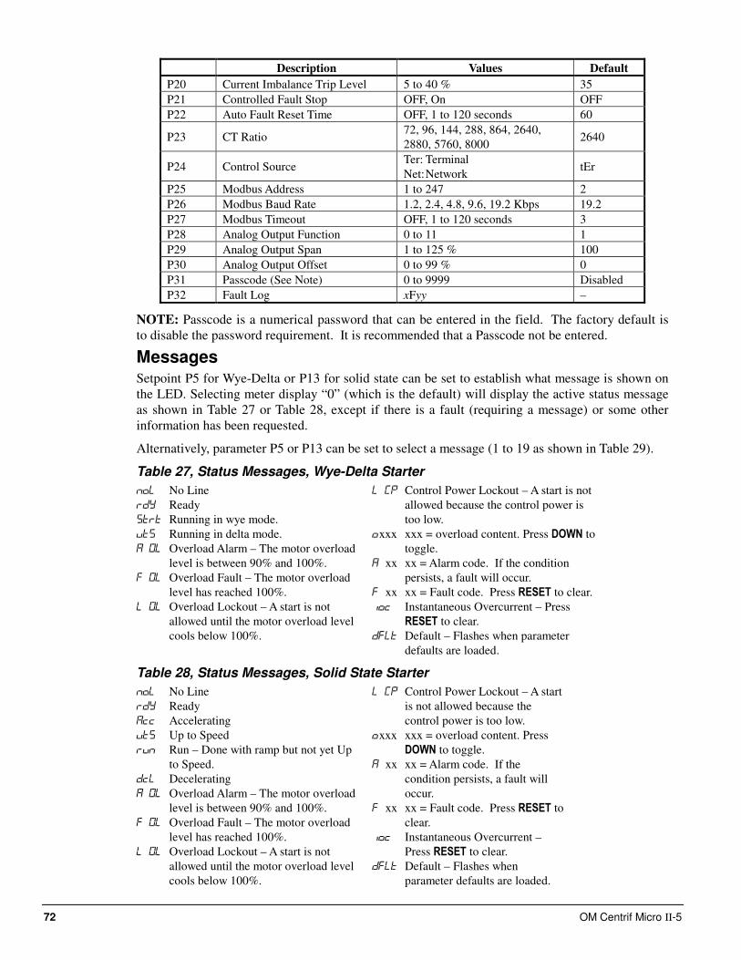
72 OM Centrif Micro ΙΙ-5
Description Values Default
P20 Current Imbalance Trip Level 5 to 40 % 35
P21 Controlled Fault Stop OFF, On OFF
P22 Auto Fault Reset Time OFF, 1 to 120 seconds 60
P23 CT Ratio 72, 96, 144, 288, 864, 2640,
2880, 5760, 8000 2640
P24 Control Source Ter: Terminal
Net: Network tEr
P25 Modbus Address 1 to 247 2
P26 Modbus Baud Rate 1.2, 2.4, 4.8, 9.6, 19.2 Kbps 19.2
P27 Modbus Timeout OFF, 1 to 120 seconds 3
P28 Analog Output Function 0 to 11 1
P29 Analog Output Span 1 to 125 % 100
P30 Analog Output Offset 0 to 99 % 0
P31 Passcode (See Note) 0 to 9999 Disabled
P32 Fault Log xFyy –
NOTE: Passcode is a numerical password that can be entered in the field. The factory default is
to disable the password requirement. It is recommended that a Passcode not be entered.
Messages Setpoint P5 for Wye-Delta or P13 for solid state can be set to establish what message is shown on
the LED. Selecting meter display “0” (which is the default) will display the active status message
as shown in Table 27 or Table 28, except if there is a fault (requiring a message) or some other
information has been requested.
Alternatively, parameter P5 or P13 can be set to select a message (1 to 19 as shown in Table 29).
Table 27, Status Messages, Wye-Delta Starter
No Line
Ready
Running in wye mode.
Running in delta mode.
Overload Alarm – The motor overload
level is between 90% and 100%.
Overload Fault – The motor overload
level has reached 100%.
Overload Lockout – A start is not
allowed until the motor overload level
cools below 100%.
Control Power Lockout – A start is not
allowed because the control power is
too low.
xxx xxx = overload content. Press DOWN to
toggle.
xx xx = Alarm code. If the condition
persists, a fault will occur.
xx xx = Fault code. Press RESET to clear.
Instantaneous Overcurrent – Press
RESET to clear.
Default – Flashes when parameter
defaults are loaded.
Table 28, Status Messages, Solid State Starter
No Line
Ready
Accelerating
Up to Speed
Run – Done with ramp but not yet Up
to Speed.
Decelerating
Overload Alarm – The motor overload
level is between 90% and 100%.
Overload Fault – The motor overload
level has reached 100%.
Overload Lockout – A start is not
allowed until the motor overload level
cools below 100%.
Control Power Lockout – A start
is not allowed because the
control power is too low.
xxx xxx = overload content. Press
DOWN to toggle.
xx xx = Alarm code. If the
condition persists, a fault will
occur.
xx xx = Fault code. Press RESET to
clear.
Instantaneous Overcurrent –
Press RESET to clear.
Default – Flashes when
parameter defaults are loaded.
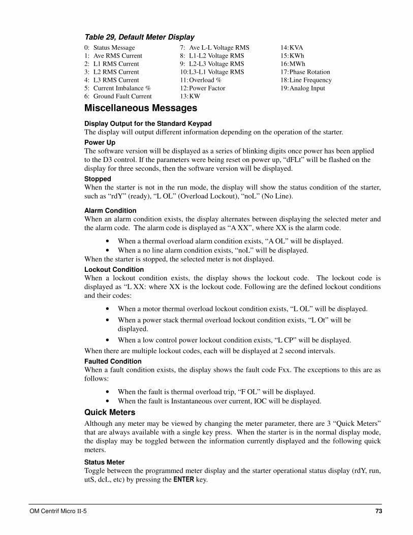
OM Centrif Micro ΙΙ-5 73
Table 29, Default Meter Display
0: Status Message
1: Ave RMS Current
2: L1 RMS Current
3: L2 RMS Current
4: L3 RMS Current
5: Current Imbalance %
6: Ground Fault Current
7: Ave L-L Voltage RMS
8: L1-L2 Voltage RMS
9: L2-L3 Voltage RMS
10: L3-L1 Voltage RMS
11: Overload %
12: Power Factor
13: KW
14: KVA
15: KWh
16: MWh
17: Phase Rotation
18: Line Frequency
19: Analog Input
Miscellaneous Messages
Display Output for the Standard Keypad
The display will output different information depending on the operation of the starter.
Power Up
The software version will be displayed as a series of blinking digits once power has been applied
to the D3 control. If the parameters were being reset on power up, “dFLt” will be flashed on the
display for three seconds, then the software version will be displayed.
Stopped
When the starter is not in the run mode, the display will show the status condition of the starter,
such as “rdY” (ready), “L OL” (Overload Lockout), “noL” (No Line).
Alarm Condition
When an alarm condition exists, the display alternates between displaying the selected meter and
the alarm code. The alarm code is displayed as “A XX”, where XX is the alarm code.
• When a thermal overload alarm condition exists, “A OL” will be displayed.
• When a no line alarm condition exists, “noL” will be displayed.
When the starter is stopped, the selected meter is not displayed.
Lockout Condition
When a lockout condition exists, the display shows the lockout code. The lockout code is
displayed as “L XX: where XX is the lockout code. Following are the defined lockout conditions
and their codes:
• When a motor thermal overload lockout condition exists, “L OL” will be displayed.
• When a power stack thermal overload lockout condition exists, “L Ot” will be
displayed.
• When a low control power lockout condition exists, “L CP” will be displayed.
When there are multiple lockout codes, each will be displayed at 2 second intervals.
Faulted Condition
When a fault condition exists, the display shows the fault code Fxx. The exceptions to this are as
follows:
• When the fault is thermal overload trip, “F OL” will be displayed.
• When the fault is Instantaneous over current, IOC will be displayed.
Quick Meters
Although any meter may be viewed by changing the meter parameter, there are 3 “Quick Meters”
that are always available with a single key press. When the starter is in the normal display mode,
the display may be toggled between the information currently displayed and the following quick
meters.
Status Meter
Toggle between the programmed meter display and the starter operational status display (rdY, run,
utS, dcL, etc) by pressing the ENTER key.
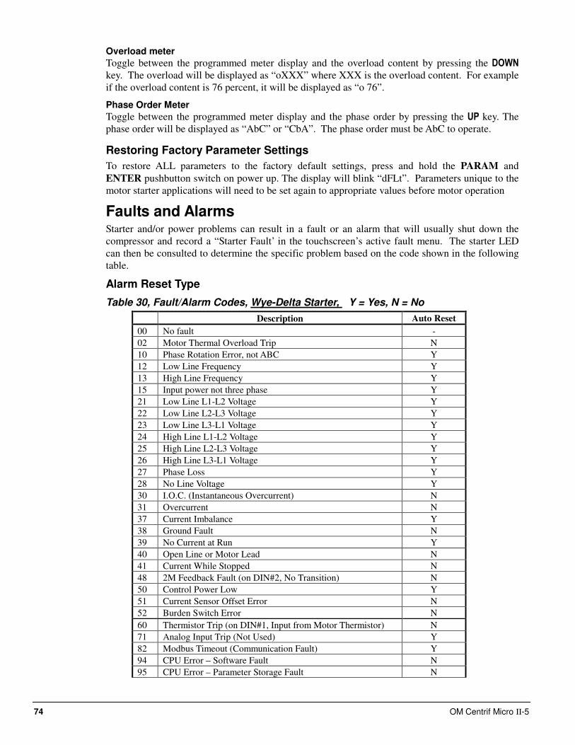
74 OM Centrif Micro ΙΙ-5
Overload meter
Toggle between the programmed meter display and the overload content by pressing the DOWN
key. The overload will be displayed as “oXXX” where XXX is the overload content. For example
if the overload content is 76 percent, it will be displayed as “o 76”.
Phase Order Meter
Toggle between the programmed meter display and the phase order by pressing the UP key. The
phase order will be displayed as “AbC” or “CbA”. The phase order must be AbC to operate.
Restoring Factory Parameter Settings
To restore ALL parameters to the factory default settings, press and hold the PARAM and
ENTER pushbutton switch on power up. The display will blink “dFLt”. Parameters unique to the
motor starter applications will need to be set again to appropriate values before motor operation
Faults and Alarms Starter and/or power problems can result in a fault or an alarm that will usually shut down the
compressor and record a “Starter Fault’ in the touchscreen’s active fault menu. The starter LED
can then be consulted to determine the specific problem based on the code shown in the following
table.
Alarm Reset Type
Table 30, Fault/Alarm Codes, Wye-Delta Starter, Y = Yes, N = No
Description Auto Reset
00 No fault -
02 Motor Thermal Overload Trip N
10 Phase Rotation Error, not ABC Y
12 Low Line Frequency Y
13 High Line Frequency Y
15 Input power not three phase Y
21 Low Line L1-L2 Voltage Y
22 Low Line L2-L3 Voltage Y
23 Low Line L3-L1 Voltage Y
24 High Line L1-L2 Voltage Y
25 High Line L2-L3 Voltage Y
26 High Line L3-L1 Voltage Y
27 Phase Loss Y
28 No Line Voltage Y
30 I.O.C. (Instantaneous Overcurrent) N
31 Overcurrent N
37 Current Imbalance Y
38 Ground Fault N
39 No Current at Run Y
40 Open Line or Motor Lead N
41 Current While Stopped N
48 2M Feedback Fault (on DIN#2, No Transition) N
50 Control Power Low Y
51 Current Sensor Offset Error N
52 Burden Switch Error N
60 Thermistor Trip (on DIN#1, Input from Motor Thermistor) N
71 Analog Input Trip (Not Used) Y
82 Modbus Timeout (Communication Fault) Y
94 CPU Error – Software Fault N
95 CPU Error – Parameter Storage Fault N
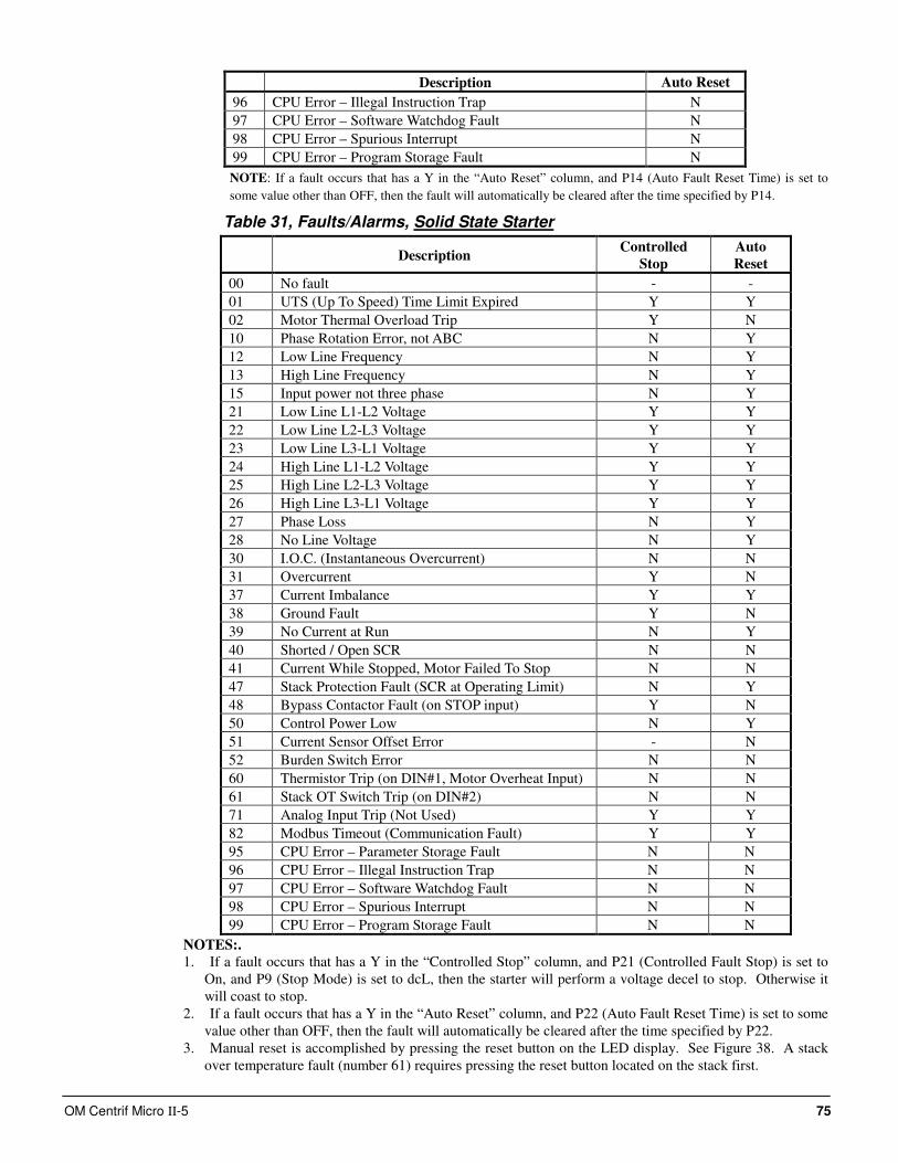
OM Centrif Micro ΙΙ-5 75
Description Auto Reset
96 CPU Error – Illegal Instruction Trap N
97 CPU Error – Software Watchdog Fault N
98 CPU Error – Spurious Interrupt N
99 CPU Error – Program Storage Fault N
NOTE: If a fault occurs that has a Y in the “Auto Reset” column, and P14 (Auto Fault Reset Time) is set to
some value other than OFF, then the fault will automatically be cleared after the time specified by P14.
Table 31, Faults/Alarms, Solid State Starter
Description Controlled
Stop
Auto
Reset
00 No fault - -
01 UTS (Up To Speed) Time Limit Expired Y Y
02 Motor Thermal Overload Trip Y N
10 Phase Rotation Error, not ABC N Y
12 Low Line Frequency N Y
13 High Line Frequency N Y
15 Input power not three phase N Y
21 Low Line L1-L2 Voltage Y Y
22 Low Line L2-L3 Voltage Y Y
23 Low Line L3-L1 Voltage Y Y
24 High Line L1-L2 Voltage Y Y
25 High Line L2-L3 Voltage Y Y
26 High Line L3-L1 Voltage Y Y
27 Phase Loss N Y
28 No Line Voltage N Y
30 I.O.C. (Instantaneous Overcurrent) N N
31 Overcurrent Y N
37 Current Imbalance Y Y
38 Ground Fault Y N
39 No Current at Run N Y
40 Shorted / Open SCR N N
41 Current While Stopped, Motor Failed To Stop N N
47 Stack Protection Fault (SCR at Operating Limit) N Y
48 Bypass Contactor Fault (on STOP input) Y N
50 Control Power Low N Y
51 Current Sensor Offset Error - N
52 Burden Switch Error N N
60 Thermistor Trip (on DIN#1, Motor Overheat Input) N N
61 Stack OT Switch Trip (on DIN#2) N N
71 Analog Input Trip (Not Used) Y Y
82 Modbus Timeout (Communication Fault) Y Y
95 CPU Error – Parameter Storage Fault N N
96 CPU Error – Illegal Instruction Trap N N
97 CPU Error – Software Watchdog Fault N N
98 CPU Error – Spurious Interrupt N N
99 CPU Error – Program Storage Fault N N
NOTES:.
1. If a fault occurs that has a Y in the “Controlled Stop” column, and P21 (Controlled Fault Stop) is set to
On, and P9 (Stop Mode) is set to dcL, then the starter will perform a voltage decel to stop. Otherwise it
will coast to stop.
2. If a fault occurs that has a Y in the “Auto Reset” column, and P22 (Auto Fault Reset Time) is set to some
value other than OFF, then the fault will automatically be cleared after the time specified by P22.
3. Manual reset is accomplished by pressing the reset button on the LED display. See Figure 38. A stack
over temperature fault (number 61) requires pressing the reset button located on the stack first.
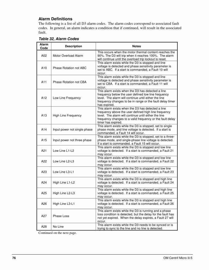
76 OM Centrif Micro ΙΙ-5
Alarm Definitions The following is a list of all D3 alarm codes. The alarm codes correspond to associated fault
codes. In general, an alarm indicates a condition that if continued, will result in the associated
fault.
Table 32, Alarm Codes
Alarm Code
Description Notes
A02 Motor Overload Alarm This occurs when the motor thermal content reaches the 90%. The D3 will trip when it reaches 100%. The alarm will continue until the overload trip lockout is reset.
A10 Phase Rotation not ABC
This alarm exists while the D3 is stopped and line voltage is detected and phase sensitivity parameter is set to ABC. If a start is commanded, a Fault 10 will occur.
A11 Phase Rotation not CBA
This alarm exists while the D3 is stopped and line voltage is detected and phase sensitivity parameter is set to CBA. If a start is commanded, a Fault 11 will occur.
A12 Low Line Frequency
This alarm exists when the D3 has detected a line frequency below the user defined low line frequency level. The alarm will continue until either the line frequency changes to be in range or the fault delay timer has expired.
A13 High Line Frequency
This alarm exists when the D3 has detected a line frequency above the user defined high line frequency level. The alarm will continue until either the line frequency changes to a valid frequency or the fault delay timer has expired.
A14 Input power not single phase This alarm exists while the D3 is stopped, set to single phase mode, and line voltage is detected. If a start is commanded, a Fault 14 will occur.
A15 Input power not three phase This alarm exists while the D3 is stopped, set to a three-phase mode, and single-phase line voltage is detected. If a start is commanded, a Fault 15 will occur.
A21 Low Line L1-L2 This alarm exists while the D3 is stopped and low line voltage is detected. If a start is commanded, a Fault 21 may occur.
A22 Low Line L2-L3 This alarm exists while the D3 is stopped and low line voltage is detected. If a start is commanded, a Fault 22 may occur.
A23 Low Line L3-L1 This alarm exists while the D3 is stopped and low line voltage is detected. If a start is commanded, a Fault 23 may occur.
A24 High Line L1-L2 This alarm exists while the D3 is stopped and high line voltage is detected. If a start is commanded, a Fault 24 may occur.
A25 High Line L2-L3 This alarm exists while the D3 is stopped and high line voltage is detected. If a start is commanded, a Fault 25 may occur.
A26 High Line L3-L1 This alarm exists while the D3 is stopped and high line voltage is detected. If a start is commanded, a Fault 26 may occur.
A27 Phase Loss
This alarm exists while the D3 is running and a phase loss condition is detected, but the delay for the fault has not yet expired. When the delay expires, a Fault 27 will occur.
A28 No Line This alarm exists while the D3 needs to be synced or is trying to sync to the line and no line is detected.
Continued on the next page.
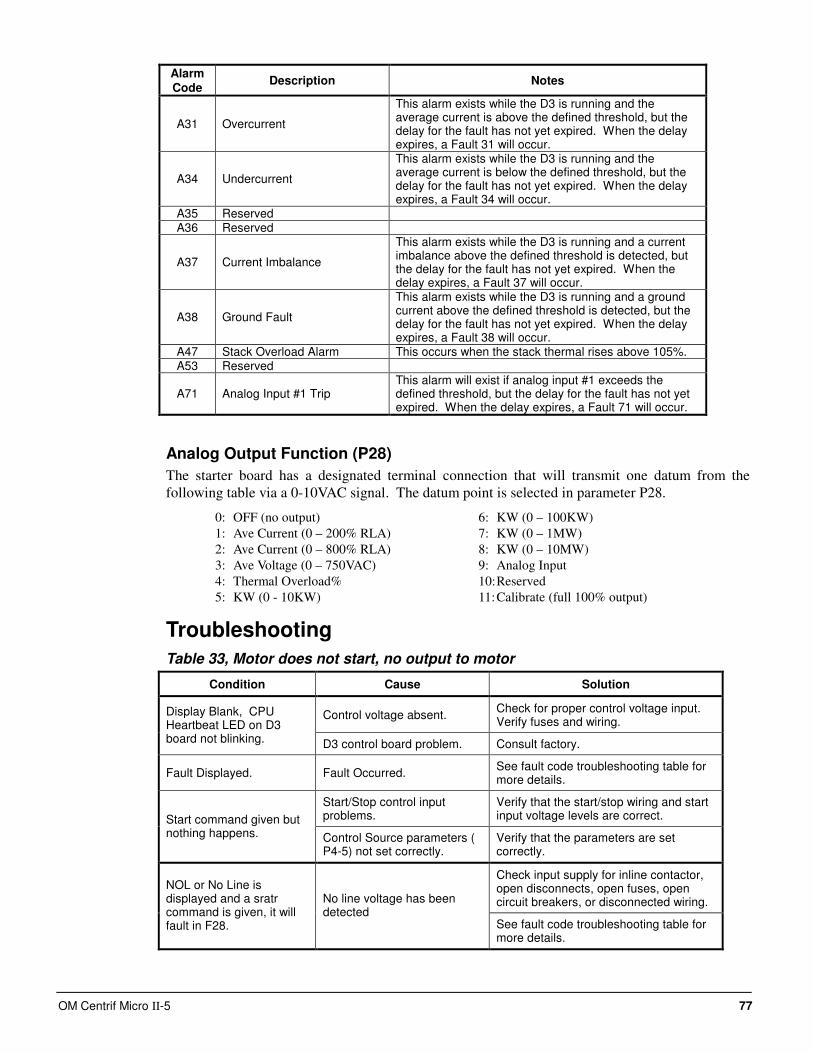
OM Centrif Micro ΙΙ-5 77
Alarm Code
Description Notes
A31 Overcurrent
This alarm exists while the D3 is running and the average current is above the defined threshold, but the delay for the fault has not yet expired. When the delay expires, a Fault 31 will occur.
A34 Undercurrent
This alarm exists while the D3 is running and the average current is below the defined threshold, but the delay for the fault has not yet expired. When the delay expires, a Fault 34 will occur.
A35 Reserved A36 Reserved
A37 Current Imbalance
This alarm exists while the D3 is running and a current imbalance above the defined threshold is detected, but the delay for the fault has not yet expired. When the delay expires, a Fault 37 will occur.
A38 Ground Fault
This alarm exists while the D3 is running and a ground current above the defined threshold is detected, but the delay for the fault has not yet expired. When the delay expires, a Fault 38 will occur.
A47 Stack Overload Alarm This occurs when the stack thermal rises above 105%. A53 Reserved
A71 Analog Input #1 Trip This alarm will exist if analog input #1 exceeds the defined threshold, but the delay for the fault has not yet expired. When the delay expires, a Fault 71 will occur.
Analog Output Function (P28)
The starter board has a designated terminal connection that will transmit one datum from the
following table via a 0-10VAC signal. The datum point is selected in parameter P28.
0: OFF (no output)
1: Ave Current (0 – 200% RLA)
2: Ave Current (0 – 800% RLA)
3: Ave Voltage (0 – 750VAC)
4: Thermal Overload%
5: KW (0 - 10KW)
6: KW (0 – 100KW)
7: KW (0 – 1MW)
8: KW (0 – 10MW)
9: Analog Input
10: Reserved
11: Calibrate (full 100% output)
Troubleshooting
Table 33, Motor does not start, no output to motor
Condition Cause Solution
Control voltage absent. Check for proper control voltage input. Verify fuses and wiring.
Display Blank, CPU Heartbeat LED on D3 board not blinking. D3 control board problem. Consult factory.
Fault Displayed. Fault Occurred. See fault code troubleshooting table for more details.
Start/Stop control input problems.
Verify that the start/stop wiring and start input voltage levels are correct. Start command given but
nothing happens. Control Source parameters ( P4-5) not set correctly.
Verify that the parameters are set correctly.
Check input supply for inline contactor, open disconnects, open fuses, open circuit breakers, or disconnected wiring.
NOL or No Line is displayed and a sratr command is given, it will fault in F28.
No line voltage has been detected
See fault code troubleshooting table for more details.
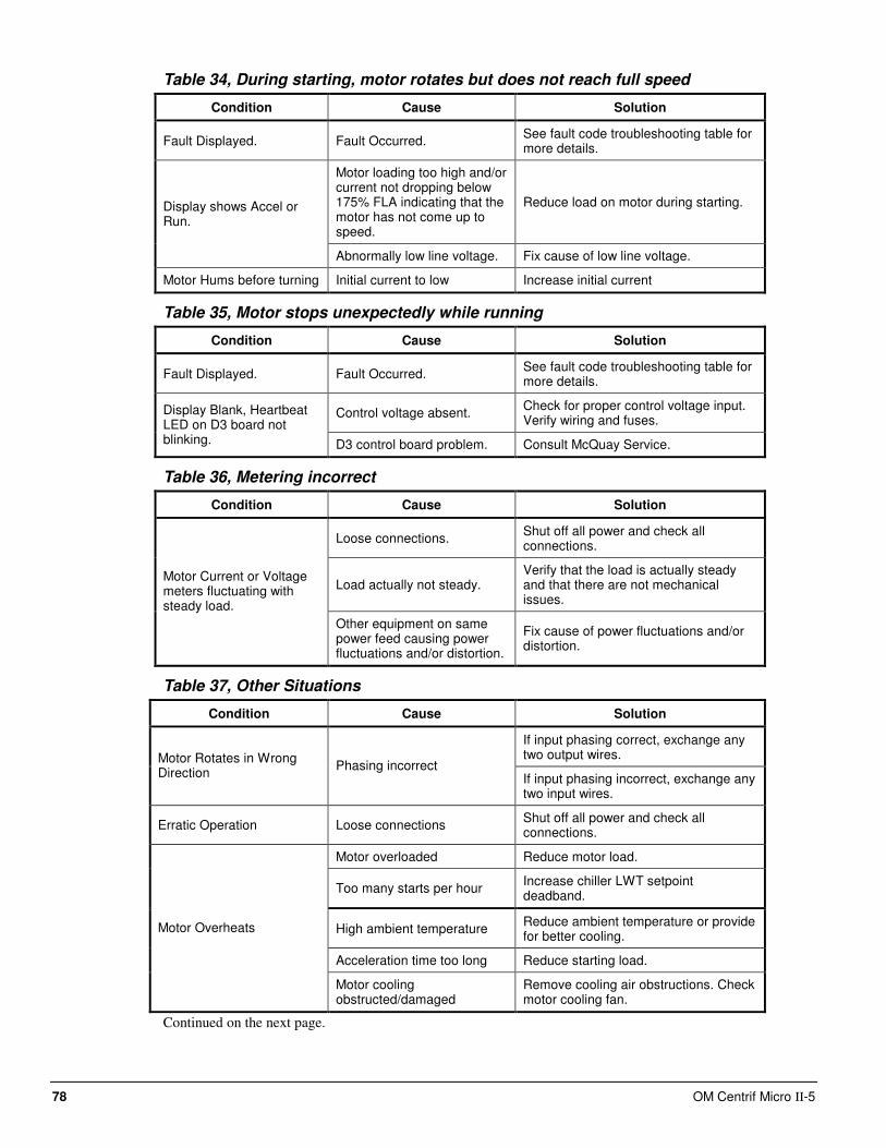
78 OM Centrif Micro ΙΙ-5
Table 34, During starting, motor rotates but does not reach full speed
Condition Cause Solution
Fault Displayed. Fault Occurred. See fault code troubleshooting table for more details.
Motor loading too high and/or current not dropping below 175% FLA indicating that the motor has not come up to speed.
Reduce load on motor during starting. Display shows Accel or Run.
Abnormally low line voltage. Fix cause of low line voltage.
Motor Hums before turning Initial current to low Increase initial current
Table 35, Motor stops unexpectedly while running
Condition Cause Solution
Fault Displayed. Fault Occurred. See fault code troubleshooting table for more details.
Control voltage absent. Check for proper control voltage input. Verify wiring and fuses.
Display Blank, Heartbeat LED on D3 board not blinking. D3 control board problem. Consult McQuay Service.
Table 36, Metering incorrect
Condition Cause Solution
Loose connections. Shut off all power and check all connections.
Load actually not steady. Verify that the load is actually steady and that there are not mechanical issues.
Motor Current or Voltage meters fluctuating with steady load.
Other equipment on same power feed causing power fluctuations and/or distortion.
Fix cause of power fluctuations and/or distortion.
Table 37, Other Situations
Condition Cause Solution
If input phasing correct, exchange any two output wires. Motor Rotates in Wrong
Direction Phasing incorrect
If input phasing incorrect, exchange any two input wires.
Erratic Operation Loose connections Shut off all power and check all connections.
Motor overloaded Reduce motor load.
Too many starts per hour Increase chiller LWT setpoint deadband.
High ambient temperature Reduce ambient temperature or provide for better cooling.
Acceleration time too long Reduce starting load.
Motor Overheats
Motor cooling obstructed/damaged
Remove cooling air obstructions. Check motor cooling fan.
Continued on the next page.
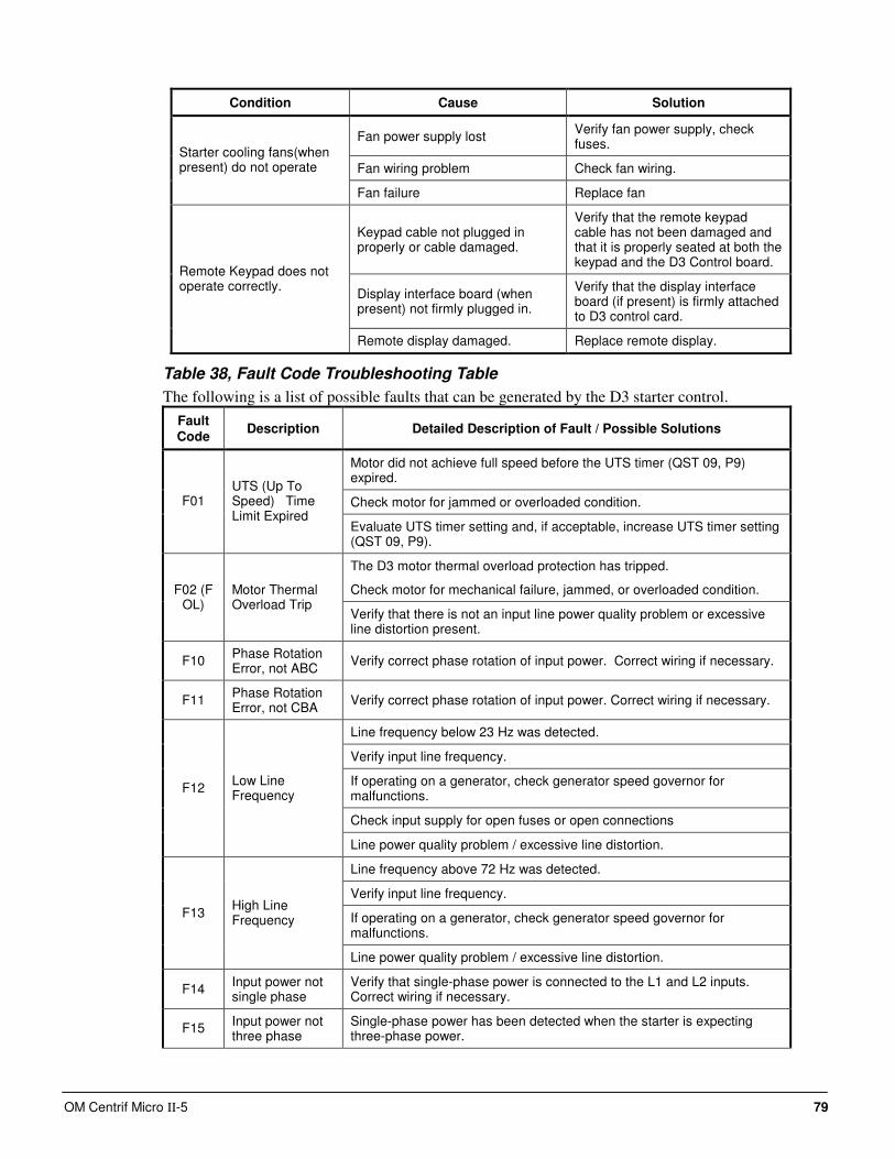
OM Centrif Micro ΙΙ-5 79
Condition Cause Solution
Fan power supply lost Verify fan power supply, check fuses.
Fan wiring problem Check fan wiring.
Starter cooling fans(when present) do not operate
Fan failure Replace fan
Keypad cable not plugged in properly or cable damaged.
Verify that the remote keypad cable has not been damaged and that it is properly seated at both the keypad and the D3 Control board.
Display interface board (when present) not firmly plugged in.
Verify that the display interface board (if present) is firmly attached to D3 control card.
Remote Keypad does not operate correctly.
Remote display damaged. Replace remote display.
Table 38, Fault Code Troubleshooting Table
The following is a list of possible faults that can be generated by the D3 starter control.
Fault Code
Description Detailed Description of Fault / Possible Solutions
Motor did not achieve full speed before the UTS timer (QST 09, P9) expired.
Check motor for jammed or overloaded condition. F01 UTS (Up To Speed) Time Limit Expired
Evaluate UTS timer setting and, if acceptable, increase UTS timer setting (QST 09, P9).
The D3 motor thermal overload protection has tripped.
Check motor for mechanical failure, jammed, or overloaded condition. F02 (F OL)
Motor Thermal Overload Trip
Verify that there is not an input line power quality problem or excessive line distortion present.
F10 Phase Rotation Error, not ABC
Verify correct phase rotation of input power. Correct wiring if necessary.
F11 Phase Rotation Error, not CBA
Verify correct phase rotation of input power. Correct wiring if necessary.
Line frequency below 23 Hz was detected.
Verify input line frequency.
If operating on a generator, check generator speed governor for malfunctions.
Check input supply for open fuses or open connections
F12 Low Line Frequency
Line power quality problem / excessive line distortion.
Line frequency above 72 Hz was detected.
Verify input line frequency.
If operating on a generator, check generator speed governor for malfunctions.
F13 High Line Frequency
Line power quality problem / excessive line distortion.
F14 Input power not single phase
Verify that single-phase power is connected to the L1 and L2 inputs. Correct wiring if necessary.
F15 Input power not three phase
Single-phase power has been detected when the starter is expecting three-phase power.
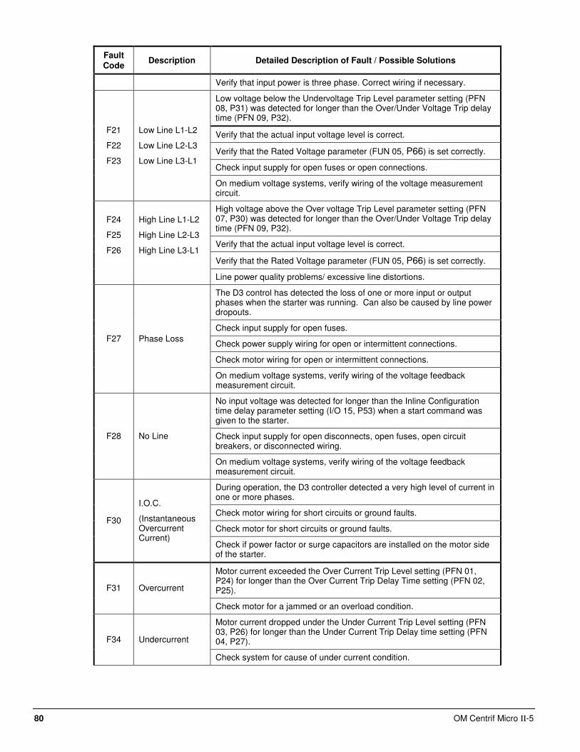
80 OM Centrif Micro ΙΙ-5
Fault Code
Description Detailed Description of Fault / Possible Solutions
Verify that input power is three phase. Correct wiring if necessary.
Low voltage below the Undervoltage Trip Level parameter setting (PFN 08, P31) was detected for longer than the Over/Under Voltage Trip delay time (PFN 09, P32).
Verify that the actual input voltage level is correct.
Verify that the Rated Voltage parameter (FUN 05, P66) is set correctly.
Check input supply for open fuses or open connections.
F21
F22
F23
Low Line L1-L2
Low Line L2-L3
Low Line L3-L1
On medium voltage systems, verify wiring of the voltage measurement circuit.
High voltage above the Over voltage Trip Level parameter setting (PFN 07, P30) was detected for longer than the Over/Under Voltage Trip delay time (PFN 09, P32).
Verify that the actual input voltage level is correct.
Verify that the Rated Voltage parameter (FUN 05, P66) is set correctly.
F24
F25
F26
High Line L1-L2
High Line L2-L3
High Line L3-L1
Line power quality problems/ excessive line distortions.
The D3 control has detected the loss of one or more input or output phases when the starter was running. Can also be caused by line power dropouts.
Check input supply for open fuses.
Check power supply wiring for open or intermittent connections.
Check motor wiring for open or intermittent connections.
F27 Phase Loss
On medium voltage systems, verify wiring of the voltage feedback measurement circuit.
No input voltage was detected for longer than the Inline Configuration time delay parameter setting (I/O 15, P53) when a start command was given to the starter.
Check input supply for open disconnects, open fuses, open circuit breakers, or disconnected wiring.
F28 No Line
On medium voltage systems, verify wiring of the voltage feedback measurement circuit.
During operation, the D3 controller detected a very high level of current in one or more phases.
Check motor wiring for short circuits or ground faults.
Check motor for short circuits or ground faults. F30
I.O.C.
(Instantaneous Overcurrent Current)
Check if power factor or surge capacitors are installed on the motor side of the starter.
Motor current exceeded the Over Current Trip Level setting (PFN 01, P24) for longer than the Over Current Trip Delay Time setting (PFN 02, P25). F31 Overcurrent
Check motor for a jammed or an overload condition.
Motor current dropped under the Under Current Trip Level setting (PFN 03, P26) for longer than the Under Current Trip Delay time setting (PFN 04, P27). F34 Undercurrent
Check system for cause of under current condition.
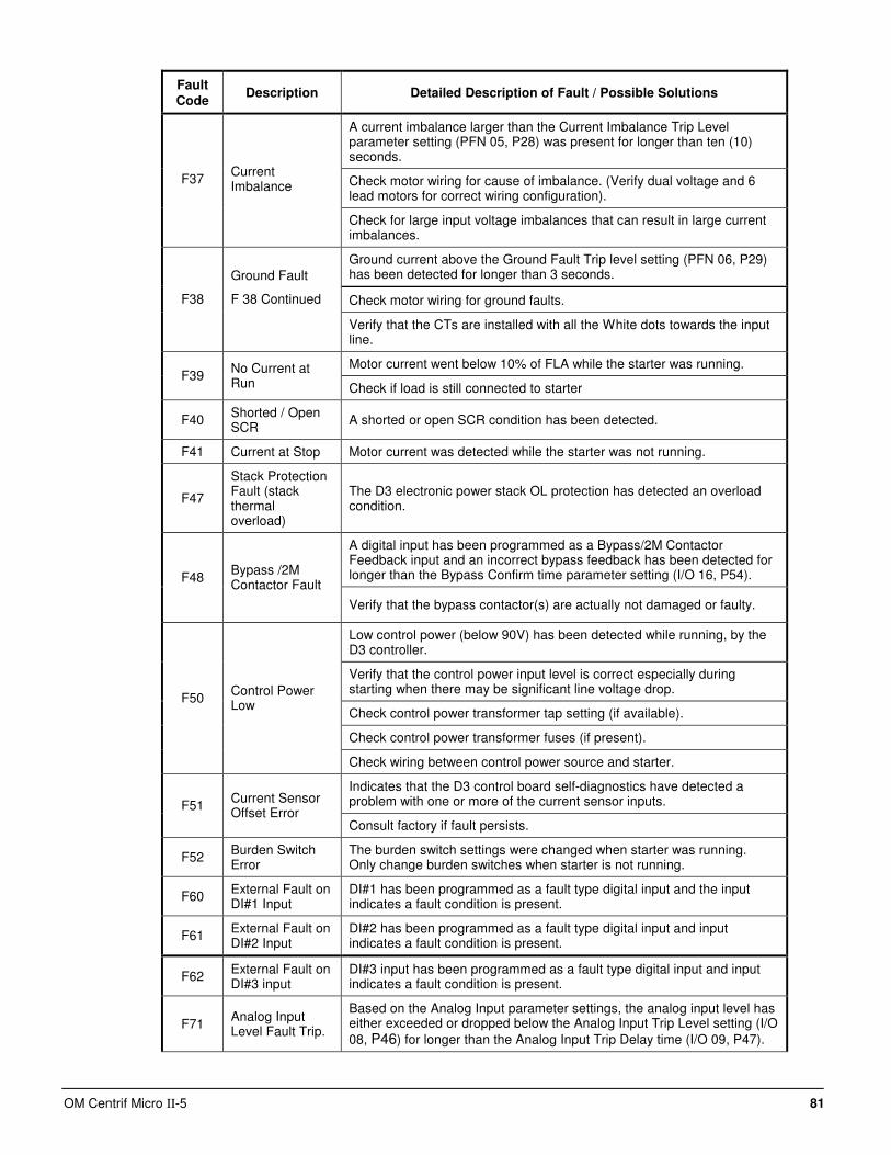
OM Centrif Micro ΙΙ-5 81
Fault Code
Description Detailed Description of Fault / Possible Solutions
A current imbalance larger than the Current Imbalance Trip Level parameter setting (PFN 05, P28) was present for longer than ten (10) seconds.
Check motor wiring for cause of imbalance. (Verify dual voltage and 6 lead motors for correct wiring configuration).
F37 Current Imbalance
Check for large input voltage imbalances that can result in large current imbalances.
Ground current above the Ground Fault Trip level setting (PFN 06, P29) has been detected for longer than 3 seconds.
Check motor wiring for ground faults. F38
Ground Fault
F 38 Continued
Verify that the CTs are installed with all the White dots towards the input line.
Motor current went below 10% of FLA while the starter was running. F39
No Current at Run Check if load is still connected to starter
F40 Shorted / Open SCR
A shorted or open SCR condition has been detected.
F41 Current at Stop Motor current was detected while the starter was not running.
F47
Stack Protection Fault (stack thermal overload)
The D3 electronic power stack OL protection has detected an overload condition.
A digital input has been programmed as a Bypass/2M Contactor Feedback input and an incorrect bypass feedback has been detected for longer than the Bypass Confirm time parameter setting (I/O 16, P54). F48
Bypass /2M Contactor Fault
Verify that the bypass contactor(s) are actually not damaged or faulty.
Low control power (below 90V) has been detected while running, by the D3 controller.
Verify that the control power input level is correct especially during starting when there may be significant line voltage drop.
Check control power transformer tap setting (if available).
Check control power transformer fuses (if present).
F50 Control Power Low
Check wiring between control power source and starter.
Indicates that the D3 control board self-diagnostics have detected a problem with one or more of the current sensor inputs. F51
Current Sensor Offset Error
Consult factory if fault persists.
F52 Burden Switch Error
The burden switch settings were changed when starter was running. Only change burden switches when starter is not running.
F60 External Fault on DI#1 Input
DI#1 has been programmed as a fault type digital input and the input indicates a fault condition is present.
F61 External Fault on DI#2 Input
DI#2 has been programmed as a fault type digital input and input indicates a fault condition is present.
F62 External Fault on DI#3 input
DI#3 input has been programmed as a fault type digital input and input indicates a fault condition is present.
F71 Analog Input Level Fault Trip.
Based on the Analog Input parameter settings, the analog input level has either exceeded or dropped below the Analog Input Trip Level setting (I/O
08, P46) for longer than the Analog Input Trip Delay time (I/O 09, P47).
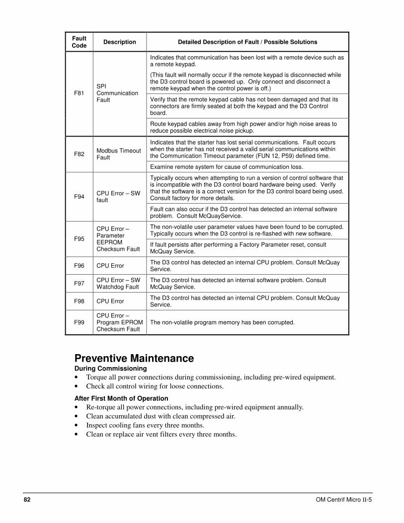
82 OM Centrif Micro ΙΙ-5
Fault Code
Description Detailed Description of Fault / Possible Solutions
Indicates that communication has been lost with a remote device such as a remote keypad.
(This fault will normally occur if the remote keypad is disconnected while the D3 control board is powered up. Only connect and disconnect a remote keypad when the control power is off.)
Verify that the remote keypad cable has not been damaged and that its connectors are firmly seated at both the keypad and the D3 Control board.
F81 SPI Communication Fault
Route keypad cables away from high power and/or high noise areas to reduce possible electrical noise pickup.
Indicates that the starter has lost serial communications. Fault occurs when the starter has not received a valid serial communications within the Communication Timeout parameter (FUN 12, P59) defined time. F82
Modbus Timeout Fault
Examine remote system for cause of communication loss.
Typically occurs when attempting to run a version of control software that is incompatible with the D3 control board hardware being used. Verify that the software is a correct version for the D3 control board being used. Consult factory for more details. F94
CPU Error – SW fault
Fault can also occur if the D3 control has detected an internal software problem. Consult McQuayService.
The non-volatile user parameter values have been found to be corrupted. Typically occurs when the D3 control is re-flashed with new software.
F95
CPU Error – Parameter EEPROM Checksum Fault
If fault persists after performing a Factory Parameter reset, consult McQuay Service.
F96 CPU Error The D3 control has detected an internal CPU problem. Consult McQuay Service.
F97 CPU Error – SW Watchdog Fault
The D3 control has detected an internal software problem. Consult McQuay Service.
F98 CPU Error The D3 control has detected an internal CPU problem. Consult McQuay Service.
F99 CPU Error – Program EPROM Checksum Fault
The non-volatile program memory has been corrupted.
Preventive Maintenance During Commissioning
• Torque all power connections during commissioning, including pre-wired equipment.
• Check all control wiring for loose connections.
After First Month of Operation
• Re-torque all power connections, including pre-wired equipment annually.
• Clean accumulated dust with clean compressed air.
• Inspect cooling fans every three months.
• Clean or replace air vent filters every three months.
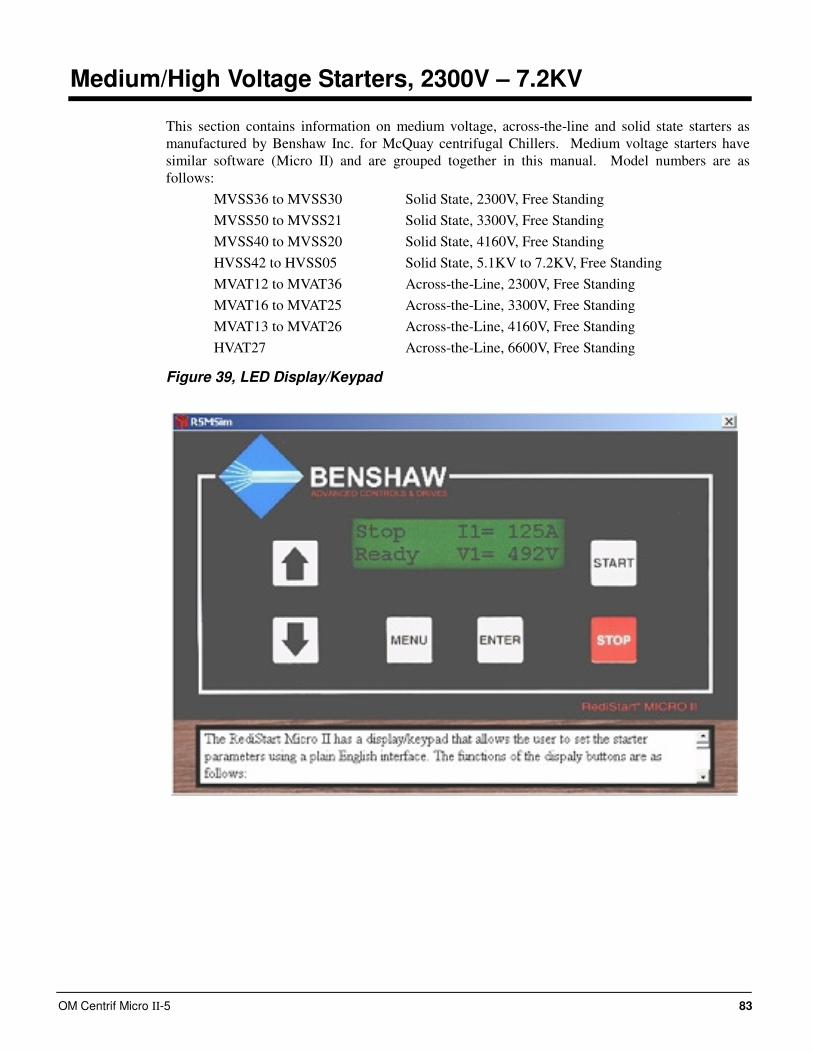
OM Centrif Micro ΙΙ-5 83
Medium/High Voltage Starters, 2300V – 7.2KV
This section contains information on medium voltage, across-the-line and solid state starters as
manufactured by Benshaw Inc. for McQuay centrifugal Chillers. Medium voltage starters have
similar software (Micro II) and are grouped together in this manual. Model numbers are as
follows:
MVSS36 to MVSS30 Solid State, 2300V, Free Standing
MVSS50 to MVSS21 Solid State, 3300V, Free Standing
MVSS40 to MVSS20 Solid State, 4160V, Free Standing
HVSS42 to HVSS05 Solid State, 5.1KV to 7.2KV, Free Standing
MVAT12 to MVAT36 Across-the-Line, 2300V, Free Standing
MVAT16 to MVAT25 Across-the-Line, 3300V, Free Standing
MVAT13 to MVAT26 Across-the-Line, 4160V, Free Standing
HVAT27 Across-the-Line, 6600V, Free Standing
Figure 39, LED Display/Keypad
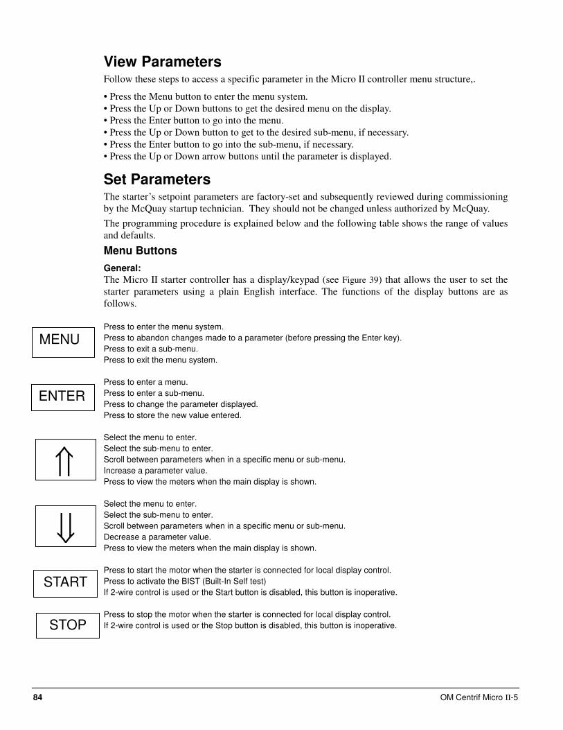
84 OM Centrif Micro ΙΙ-5
View Parameters Follow these steps to access a specific parameter in the Micro II controller menu structure,.
• Press the Menu button to enter the menu system.
• Press the Up or Down buttons to get the desired menu on the display.
• Press the Enter button to go into the menu.
• Press the Up or Down button to get to the desired sub-menu, if necessary.
• Press the Enter button to go into the sub-menu, if necessary.
• Press the Up or Down arrow buttons until the parameter is displayed.
Set Parameters The starter’s setpoint parameters are factory-set and subsequently reviewed during commissioning
by the McQuay startup technician. They should not be changed unless authorized by McQuay.
The programming procedure is explained below and the following table shows the range of values
and defaults.
Menu Buttons
General:
The Micro II starter controller has a display/keypad (see Figure 39) that allows the user to set the
starter parameters using a plain English interface. The functions of the display buttons are as
follows.
Press to enter the menu system.
Press to abandon changes made to a parameter (before pressing the Enter key).
Press to exit a sub-menu.
Press to exit the menu system.
Press to enter a menu.
Press to enter a sub-menu.
Press to change the parameter displayed.
Press to store the new value entered.
Select the menu to enter.
Select the sub-menu to enter.
Scroll between parameters when in a specific menu or sub-menu.
Increase a parameter value.
Press to view the meters when the main display is shown.
Select the menu to enter.
Select the sub-menu to enter.
Scroll between parameters when in a specific menu or sub-menu.
Decrease a parameter value.
Press to view the meters when the main display is shown.
Press to start the motor when the starter is connected for local display control.
Press to activate the BIST (Built-In Self test)
If 2-wire control is used or the Start button is disabled, this button is inoperative.
Press to stop the motor when the starter is connected for local display control.
If 2-wire control is used or the Stop button is disabled, this button is inoperative.
MENU
ENTER
START
⇑
⇓
STOP
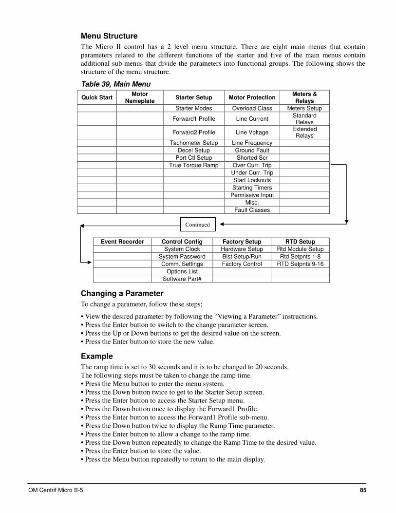
OM Centrif Micro ΙΙ-5 85
Menu Structure
The Micro II control has a 2 level menu structure. There are eight main menus that contain
parameters related to the different functions of the starter and five of the main menus contain
additional sub-menus that divide the parameters into functional groups. The following shows the
structure of the menu structure.
Table 39, Main Menu
Quick Start Motor
Nameplate Starter Setup Motor Protection
Meters & Relays
Starter Modes Overload Class Meters Setup
Forward1 Profile Line Current Standard Relays
Forward2 Profile Line Voltage Extended
Relays
Tachometer Setup Line Frequency
Decel Setup Ground Fault
Port Ctl Setup Shorted Scr
True Torque Ramp Over Curr. Trip
Under Curr. Trip
Start Lockouts
Starting Timers
Permissive Input
Misc.
Fault Classes
Event Recorder Control Config Factory Setup RTD Setup
System Clock Hardware Setup Rtd Module Setup
System Password Bist Setup/Run Rtd Setpnts 1-8
Comm. Settings Factory Control RTD Setpnts 9-16
Options List
Software Part#
Changing a Parameter
To change a parameter, follow these steps;
• View the desired parameter by following the “Viewing a Parameter” instructions.
• Press the Enter button to switch to the change parameter screen.
• Press the Up or Down buttons to get the desired value on the screen.
• Press the Enter button to store the new value.
Example
The ramp time is set to 30 seconds and it is to be changed to 20 seconds.
The following steps must be taken to change the ramp time.
• Press the Menu button to enter the menu system.
• Press the Down button twice to get to the Starter Setup screen.
• Press the Enter button to access the Starter Setup menu.
• Press the Down button once to display the Forward1 Profile.
• Press the Enter button to access the Forward1 Profile sub-menu.
• Press the Down button twice to display the Ramp Time parameter.
• Press the Enter button to allow a change to the ramp time.
• Press the Down button repeatedly to change the Ramp Time to the desired value.
• Press the Enter button to store the value.
• Press the Menu button repeatedly to return to the main display.
Continued
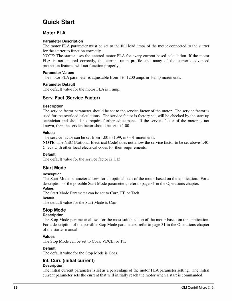
86 OM Centrif Micro ΙΙ-5
Quick Start
Motor FLA
Parameter Description
The motor FLA parameter must be set to the full load amps of the motor connected to the starter
for the starter to function correctly.
NOTE: The starter uses the entered motor FLA for every current based calculation. If the motor
FLA is not entered correctly, the current ramp profile and many of the starter’s advanced
protection features will not function properly.
Parameter Values
The motor FLA parameter is adjustable from 1 to 1200 amps in 1-amp increments.
Parameter Default
The default value for the motor FLA is 1 amp.
Serv. Fact (Service Factor)
Description
The service factor parameter should be set to the service factor of the motor. The service factor is
used for the overload calculations. The service factor is factory set, will be checked by the start-up
technician and should not require further adjustment. If the service factor of the motor is not
known, then the service factor should be set to 1.00.
Values
The service factor can be set from 1.00 to 1.99, in 0.01 increments.
NOTE: The NEC (National Electrical Code) does not allow the service factor to be set above 1.40.
Check with other local electrical codes for their requirements.
Default
The default value for the service factor is 1.15.
Start Mode
Description
The Start Mode parameter allows for an optimal start of the motor based on the application. For a
description of the possible Start Mode parameters, refer to page 31 in the Operations chapter. Values
The Start Mode Parameter can be set to Curr, TT, or Tach. Default
The default value for the Start Mode is Curr.
Stop Mode Description
The Stop Mode parameter allows for the most suitable stop of the motor based on the application.
For a description of the possible Stop Mode parameters, refer to page 31 in the Operations chapter
of the starter manual.
Values
The Stop Mode can be set to Coas, VDCL, or TT.
Default
The default value for the Stop Mode is Coas.
Int. Curr. (initial current) Description
The initial current parameter is set as a percentage of the motor FLA parameter setting. The initial
current parameter sets the current that will initially reach the motor when a start is commanded.
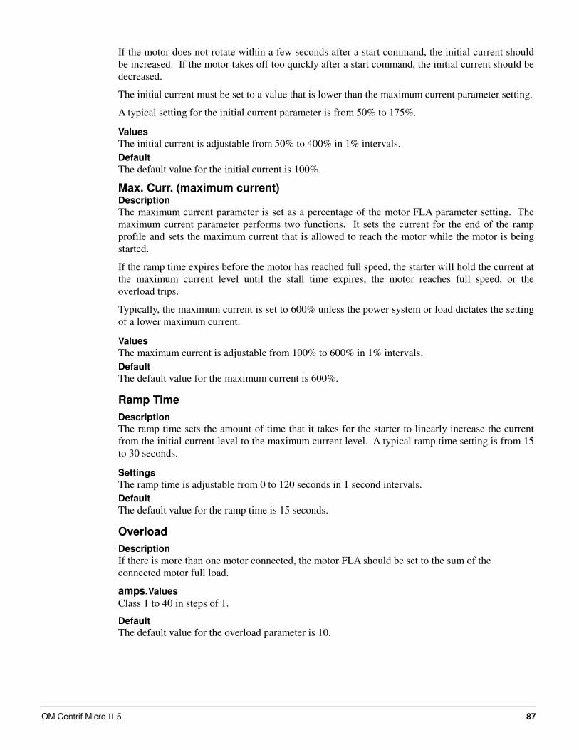
OM Centrif Micro ΙΙ-5 87
If the motor does not rotate within a few seconds after a start command, the initial current should
be increased. If the motor takes off too quickly after a start command, the initial current should be
decreased.
The initial current must be set to a value that is lower than the maximum current parameter setting.
A typical setting for the initial current parameter is from 50% to 175%.
Values
The initial current is adjustable from 50% to 400% in 1% intervals.
Default
The default value for the initial current is 100%.
Max. Curr. (maximum current) Description
The maximum current parameter is set as a percentage of the motor FLA parameter setting. The
maximum current parameter performs two functions. It sets the current for the end of the ramp
profile and sets the maximum current that is allowed to reach the motor while the motor is being
started.
If the ramp time expires before the motor has reached full speed, the starter will hold the current at
the maximum current level until the stall time expires, the motor reaches full speed, or the
overload trips.
Typically, the maximum current is set to 600% unless the power system or load dictates the setting
of a lower maximum current.
Values
The maximum current is adjustable from 100% to 600% in 1% intervals.
Default
The default value for the maximum current is 600%.
Ramp Time
Description
The ramp time sets the amount of time that it takes for the starter to linearly increase the current
from the initial current level to the maximum current level. A typical ramp time setting is from 15
to 30 seconds.
Settings
The ramp time is adjustable from 0 to 120 seconds in 1 second intervals.
Default
The default value for the ramp time is 15 seconds.
Overload
Description
If there is more than one motor connected, the motor FLA should be set to the sum of the
connected motor full load.
amps.Values
Class 1 to 40 in steps of 1.
Default
The default value for the overload parameter is 10.
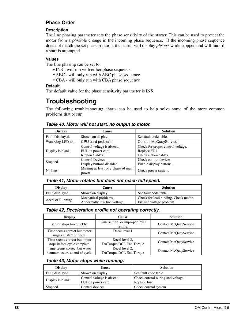
88 OM Centrif Micro ΙΙ-5
Phase Order
Description
The line phasing parameter sets the phase sensitivity of the starter. This can be used to protect the
motor from a possible change in the incoming phase sequence. If the incoming phase sequence
does not match the set phase rotation, the starter will display phs err while stopped and will fault if
a start is attempted.
Values
The line phasing can be set to:
• INS - will run with either phase sequence
• ABC - will only run with ABC phase sequence
• CBA - will only run with CBA phase sequence
Default
The default value for the phase sensitivity parameter is INS.
Troubleshooting The following troubleshooting charts can be used to help solve some of the more common
problems that occur.
Table 40, Motor will not start, no output to motor.
Display Cause Solution
Fault Displayed. Shown on display. See fault code table. Watchdog LED on. CPU card problem. Consult McQuayService.
Display is blank. Control voltage is absent.
FU1 on power card.
Ribbon Cables.
Check for proper control voltage.
Replace FU1.
Check ribbon cables.
Stopped Control Devices
Display buttons disabled. Check control devices
Enable display buttons.
No line Missing at least one phase of main
power Check power system.
Table 41, Motor rotates but does not reach full speed.
Display Cause Solution
Fault displayed. Shown on display See fault code table.
Accel or Running Mechanical problems.
Abnormally low line voltage. Check for load binding. Check motor.
Fix line voltage problem
Table 42, Deceleration profile not operating correctly.
Display Cause Solution
Motor stops too quickly. Time setting. or improper level
setting. Contact McQuayService
Time seems correct but motor
surges at start of decel.
Decel level 1
Contact McQuayService
Time seems correct but motor
stops before cycle complete.
Decel level 2.
TruTorque DCL End Torque Contact McQuayService
Time seems correct but water
hammer occurs at end of cycle.
Decel level 2.
TruTorque DCL End Torque Contact McQuayService
Table 43, Motor stops while running.
Display Cause Solution
Fault displayed. Shown on display. See fault code table.
Display is blank. Control voltage is absent.
FU1 on power card Check control wiring and voltage.
Replace fuse. Stopped Control devices. Check control system.
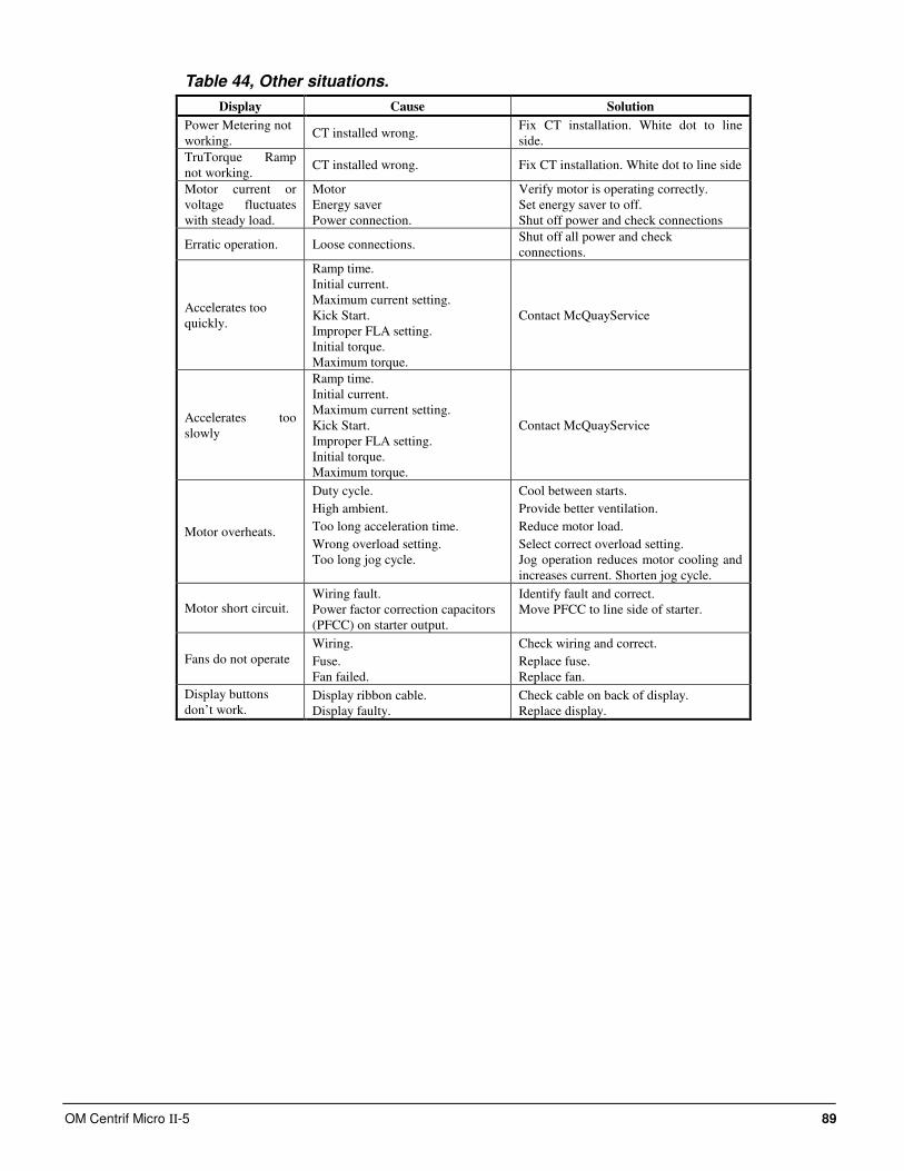
OM Centrif Micro ΙΙ-5 89
Table 44, Other situations.
Display Cause Solution
Power Metering not
working. CT installed wrong.
Fix CT installation. White dot to line
side.
TruTorque Ramp
not working. CT installed wrong. Fix CT installation. White dot to line side
Motor current or
voltage fluctuates
with steady load.
Motor
Energy saver
Power connection.
Verify motor is operating correctly.
Set energy saver to off.
Shut off power and check connections
Erratic operation. Loose connections. Shut off all power and check
connections.
Accelerates too
quickly.
Ramp time.
Initial current.
Maximum current setting.
Kick Start.
Improper FLA setting.
Initial torque.
Maximum torque.
Contact McQuayService
Accelerates too
slowly
Ramp time.
Initial current.
Maximum current setting.
Kick Start.
Improper FLA setting.
Initial torque.
Maximum torque.
Contact McQuayService
Motor overheats.
Duty cycle.
High ambient.
Too long acceleration time.
Wrong overload setting.
Too long jog cycle.
Cool between starts.
Provide better ventilation.
Reduce motor load.
Select correct overload setting.
Jog operation reduces motor cooling and
increases current. Shorten jog cycle.
Motor short circuit. Wiring fault.
Power factor correction capacitors
(PFCC) on starter output.
Identify fault and correct.
Move PFCC to line side of starter.
Fans do not operate
Wiring.
Fuse.
Fan failed.
Check wiring and correct.
Replace fuse.
Replace fan.
Display buttons
don’t work. Display ribbon cable.
Display faulty.
Check cable on back of display.
Replace display.
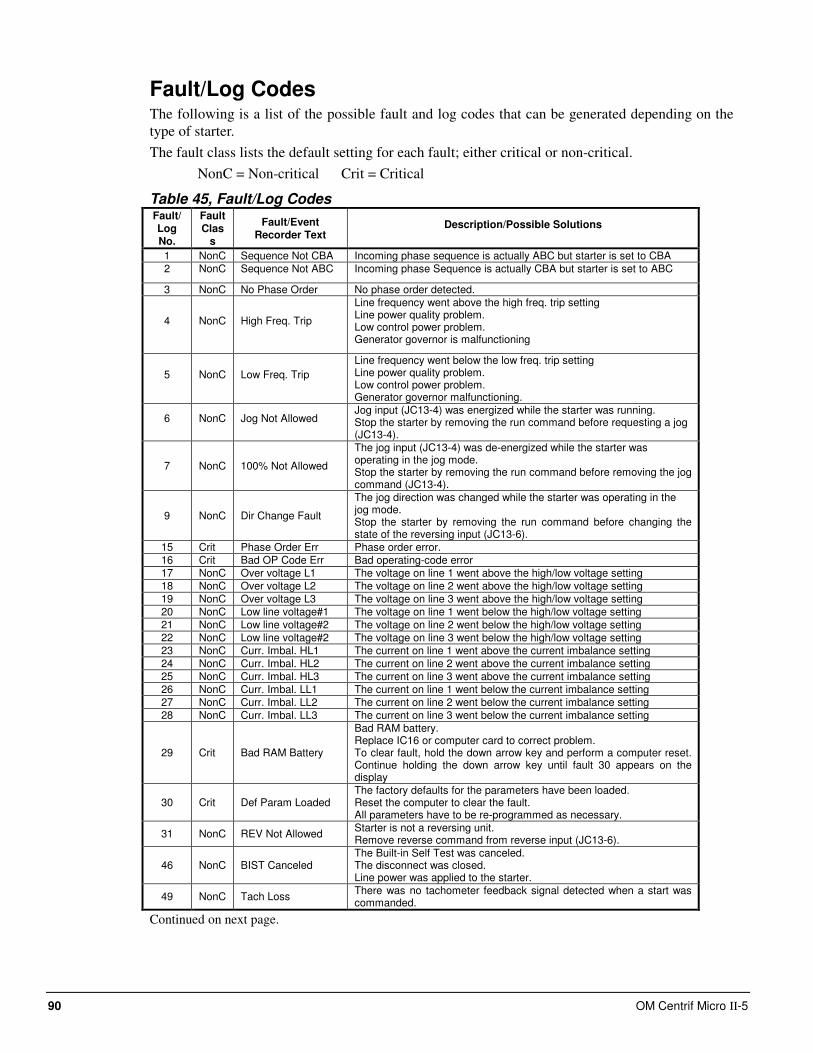
90 OM Centrif Micro ΙΙ-5
Fault/Log Codes The following is a list of the possible fault and log codes that can be generated depending on the
type of starter.
The fault class lists the default setting for each fault; either critical or non-critical.
NonC = Non-critical Crit = Critical
Table 45, Fault/Log Codes Fault/ Log No.
Fault Clas
s
Fault/Event Recorder Text
Description/Possible Solutions
1 NonC Sequence Not CBA Incoming phase sequence is actually ABC but starter is set to CBA
2 NonC Sequence Not ABC Incoming phase Sequence is actually CBA but starter is set to ABC
3 NonC No Phase Order No phase order detected.
4 NonC High Freq. Trip
Line frequency went above the high freq. trip setting Line power quality problem. Low control power problem. Generator governor is malfunctioning
5 NonC Low Freq. Trip
Line frequency went below the low freq. trip setting Line power quality problem. Low control power problem. Generator governor malfunctioning.
6 NonC Jog Not Allowed Jog input (JC13-4) was energized while the starter was running. Stop the starter by removing the run command before requesting a jog (JC13-4).
7 NonC 100% Not Allowed
The jog input (JC13-4) was de-energized while the starter was operating in the jog mode. Stop the starter by removing the run command before removing the jog command (JC13-4).
9 NonC Dir Change Fault
The jog direction was changed while the starter was operating in the jog mode. Stop the starter by removing the run command before changing the state of the reversing input (JC13-6).
15 Crit Phase Order Err Phase order error.
16 Crit Bad OP Code Err Bad operating-code error
17 NonC Over voltage L1 The voltage on line 1 went above the high/low voltage setting
18 NonC Over voltage L2 The voltage on line 2 went above the high/low voltage setting
19 NonC Over voltage L3 The voltage on line 3 went above the high/low voltage setting
20 NonC Low line voltage#1 The voltage on line 1 went below the high/low voltage setting
21 NonC Low line voltage#2 The voltage on line 2 went below the high/low voltage setting
22 NonC Low line voltage#2 The voltage on line 3 went below the high/low voltage setting
23 NonC Curr. Imbal. HL1 The current on line 1 went above the current imbalance setting
24 NonC Curr. Imbal. HL2 The current on line 2 went above the current imbalance setting
25 NonC Curr. Imbal. HL3 The current on line 3 went above the current imbalance setting
26 NonC Curr. Imbal. LL1 The current on line 1 went below the current imbalance setting
27 NonC Curr. Imbal. LL2 The current on line 2 went below the current imbalance setting
28 NonC Curr. Imbal. LL3 The current on line 3 went below the current imbalance setting
29 Crit Bad RAM Battery
Bad RAM battery. Replace IC16 or computer card to correct problem. To clear fault, hold the down arrow key and perform a computer reset. Continue holding the down arrow key until fault 30 appears on the display
30 Crit Def Param Loaded
The factory defaults for the parameters have been loaded. Reset the computer to clear the fault. All parameters have to be re-programmed as necessary.
31 NonC REV Not Allowed Starter is not a reversing unit. Remove reverse command from reverse input (JC13-6).
46 NonC BIST Canceled
The Built-in Self Test was canceled. The disconnect was closed. Line power was applied to the starter.
49 NonC Tach Loss There was no tachometer feedback signal detected when a start was commanded.
Continued on next page.
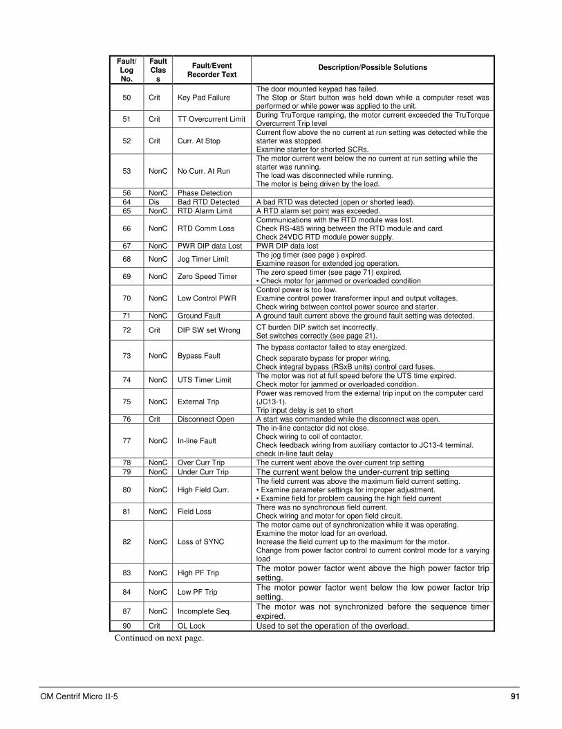
OM Centrif Micro ΙΙ-5 91
Fault/ Log No.
Fault Clas
s
Fault/Event Recorder Text
Description/Possible Solutions
50 Crit Key Pad Failure
The door mounted keypad has failed. The Stop or Start button was held down while a computer reset was performed or while power was applied to the unit.
51 Crit TT Overcurrent Limit During TruTorque ramping, the motor current exceeded the TruTorque Overcurrent Trip level
52 Crit Curr. At Stop
Current flow above the no current at run setting was detected while the starter was stopped. Examine starter for shorted SCRs.
53 NonC No Curr. At Run
The motor current went below the no current at run setting while the starter was running. The load was disconnected while running. The motor is being driven by the load.
56 NonC Phase Detection
64 Dis Bad RTD Detected A bad RTD was detected (open or shorted lead).
65 NonC RTD Alarm Limit A RTD alarm set point was exceeded.
66 NonC RTD Comm Loss
Communications with the RTD module was lost. Check RS-485 wiring between the RTD module and card. Check 24VDC RTD module power supply.
67 NonC PWR DIP data Lost PWR DIP data lost
68 NonC Jog Timer Limit The jog timer (see page ) expired. Examine reason for extended jog operation.
69 NonC Zero Speed Timer The zero speed timer (see page 71) expired. • Check motor for jammed or overloaded condition
70 NonC Low Control PWR
Control power is too low. Examine control power transformer input and output voltages. Check wiring between control power source and starter.
71 NonC Ground Fault A ground fault current above the ground fault setting was detected.
72 Crit DIP SW set Wrong CT burden DIP switch set incorrectly. Set switches correctly (see page 21).
73 NonC Bypass Fault The bypass contactor failed to stay energized.
Check separate bypass for proper wiring. Check integral bypass (RSxB units) control card fuses.
74 NonC UTS Timer Limit The motor was not at full speed before the UTS time expired. Check motor for jammed or overloaded condition.
75 NonC External Trip
Power was removed from the external trip input on the computer card (JC13-1). Trip input delay is set to short
76 Crit Disconnect Open A start was commanded while the disconnect was open.
77 NonC In-line Fault
The in-line contactor did not close. Check wiring to coil of contactor. Check feedback wiring from auxiliary contactor to JC13-4 terminal. check in-line fault delay
78 NonC Over Curr Trip The current went above the over-current trip setting
79 NonC Under Curr Trip The current went below the under-current trip setting
80 NonC High Field Curr. The field current was above the maximum field current setting. • Examine parameter settings for improper adjustment. • Examine field for problem causing the high field current
81 NonC Field Loss There was no synchronous field current. Check wiring and motor for open field circuit.
82 NonC Loss of SYNC
The motor came out of synchronization while it was operating. Examine the motor load for an overload. Increase the field current up to the maximum for the motor. Change from power factor control to current control mode for a varying load
83 NonC High PF Trip The motor power factor went above the high power factor trip setting.
84 NonC Low PF Trip The motor power factor went below the low power factor trip setting.
87 NonC Incomplete Seq. The motor was not synchronized before the sequence timer expired.
90 Crit OL Lock Used to set the operation of the overload.
Continued on next page.
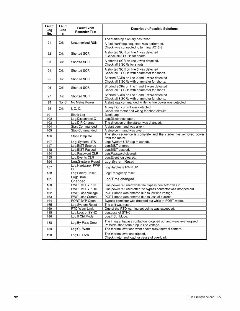
92 OM Centrif Micro ΙΙ-5
Fault/ Log No.
Fault Clas
s
Fault/Event Recorder Text
Description/Possible Solutions
91 Crit Unauthorized RUN
The start/stop circuitry has failed.
A fast start/stop sequence was performed. Check wire connected to terminal JC13-3.
92 Crit Shorted SCR A shorted SCR on line 1 was detected • Check all 3 SCRs for shorts
93 Crit Shorted SCR A shorted SCR on line 2 was detected. Check all 3 SCRs for shorts
94 Crit Shorted SCR A shorted SCR on line 3 was detected Check all 3 SCRs with ohmmeter for shorts.
95 Crit Shorted SCR Shorted SCRs on line 2 and 3 were detected Check all 3 SCRs with ohmmeter for shorts.
96 Crit Shorted SCR Shorted SCRs on line 1 and 3 were detected Check all 3 SCRs with ohmmeter for shorts.
97 Crit Shorted SCR Shorted SCRs on line 1 and 2 were detected Check all 3 SCRs with ohmmeter for shorts.
98 NonC No Mains Power A start was commanded while no line power was detected.
99 Crit I. O. C. A very high current was detected. Check the motor and wiring for short circuits.
101 Blank Log Blank Log.
102 Log:Disconnect O Log:Disconnect open.
103 Log:DIR Change The direction of the starter was changed.
104 Start Commanded A start command was given.
105 Stop Commanded A stop command was given.
106 Stop Complete The stop sequence is complete and the starter has removed power from the motor.
107 Log: System UTS Log: System UTS (up to speed).
147 Log:BIST Entered Log:BIST entered.
148 Log:BIST Passed Log:BIST passed.
154 Log:Password CLR Log:Password cleared.
155 Log:Events CLR Log:Event log cleared.
156 Log:System Reset Log:System Reset.
157 Log:Hardware PWR UP
Log:Hardware PWR UP.
158 Log:Emerg Reset Log:Emergency reset.
159 Log:Time Changed
Log:Time changed.
160 PWR Ret BYP IN Line power returned while the bypass contactor was in.
161 PWR Ret BYP OUT Line power returned after the bypass contactor was dropped out.
162 PWR Loss Voltage PORT mode was entered due to low line voltage.
163 PWR Loss Current PORT mode was entered due to loss of current.
164 PORT BYP Open Bypass contactor was dropped out while in PORT mode.
165 Log:System Reset The unit was reset.
169 RTD Warn Limit One of the RTD warning set points was exceeded.
185 Log:Loss of SYNC Log:Loss of SYNC.
186 Log:If Ctrl Mode Log:If Ctrl Mode.
188 Log:By-Pass Drop The integral bypass contactors dropped out and were re-energized. Possible short term drop in line voltage.
189 Log:OL Warn The thermal overload went above 90% thermal content.
190 Log:OL Lock The thermal overload tripped. Check motor and load for cause of overload.
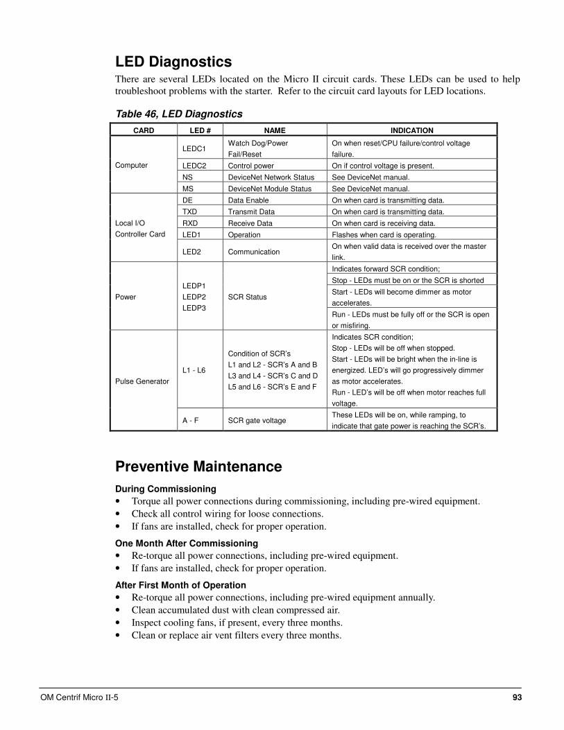
OM Centrif Micro ΙΙ-5 93
LED Diagnostics There are several LEDs located on the Micro II circuit cards. These LEDs can be used to help
troubleshoot problems with the starter. Refer to the circuit card layouts for LED locations.
Table 46, LED Diagnostics
CARD LED # NAME INDICATION
LEDC1 Watch Dog/Power
Fail/Reset
On when reset/CPU failure/control voltage
failure.
LEDC2 Control power On if control voltage is present.
NS DeviceNet Network Status See DeviceNet manual.
Computer
MS DeviceNet Module Status See DeviceNet manual.
DE Data Enable On when card is transmitting data.
TXD Transmit Data On when card is transmitting data.
RXD Receive Data On when card is receiving data.
LED1 Operation Flashes when card is operating.
Local I/O
Controller Card
LED2 Communication On when valid data is received over the master
link.
Indicates forward SCR condition;
Stop - LEDs must be on or the SCR is shorted
Start - LEDs will become dimmer as motor
accelerates. Power
LEDP1
LEDP2
LEDP3
SCR Status
Run - LEDs must be fully off or the SCR is open
or misfiring.
L1 - L6
Condition of SCR’s
L1 and L2 - SCR’s A and B
L3 and L4 - SCR’s C and D
L5 and L6 - SCR’s E and F
Indicates SCR condition;
Stop - LEDs will be off when stopped.
Start - LEDs will be bright when the in-line is
energized. LED’s will go progressively dimmer
as motor accelerates.
Run - LED’s will be off when motor reaches full
voltage.
Pulse Generator
A - F SCR gate voltage These LEDs will be on, while ramping, to
indicate that gate power is reaching the SCR’s.
Preventive Maintenance
During Commissioning
• Torque all power connections during commissioning, including pre-wired equipment.
• Check all control wiring for loose connections.
• If fans are installed, check for proper operation.
One Month After Commissioning
• Re-torque all power connections, including pre-wired equipment.
• If fans are installed, check for proper operation.
After First Month of Operation
• Re-torque all power connections, including pre-wired equipment annually.
• Clean accumulated dust with clean compressed air.
• Inspect cooling fans, if present, every three months.
• Clean or replace air vent filters every three months.
94 OM Centrif Micro ΙΙ-5
Sequence of Operation
Unit Operation The following sequence of events describes a typical WDC start and second compressor staging
process. All the contingency features of the code are not necessarily included. The purpose of this
document is to provide the operator with some insight into how the centrifugal chiller distributed
control process works to start and stage compressors.
The code was laid out to control four chillers with four compressors on each chiller. The polling
routine described below searches for all possible compressors (16 total), the code works the same
rather in a standalone WSC, or in a Dual (2 chiller) WDC setup. The Max Comp On setpoint is
used to limit the number of compressors that can run at one time (not the number being polled).
Chiller Starting
1. When the Unit state is switched to Auto, the compressors on a dual, or multi-compressor setup,
poll each other (1 to 2 minutes) to determine which will be NEXT_ON. The outcome of the
NEXT_ON search is determined by the Staging Sequence selected by the operator. Only one
compressor at a time can be selected to be NEXT_ON, and only compressors without active
alarms. The NEXT_ON status is indicated by lighting the right arrow button on that
compressor's controller keypad. If the NEXT_ON compressor has Start-to-Start or Stop-to-
Start timers running, the chiller will wait for them to clear.
2. When the Unit controller receives the NEXT_ON flag from one of it’s compressors, it will
start it’s Evap Pump (Evap Start State) and wait for the Recirculation time, at a minimum, then
it will wait "till the end of time" for the flow switch to close. When flow is confirmed, the
Evap State will switch to Run.
3. Approximately one min after NEXT_ON is set in the compressor, the compressor will look at
the Evap LWT to determine if Start-Delta-T has been exceeded. If so the Stage-Up-Now flag
is set, and if Evap State equals Run, the compressor start sequence will begin [Comp Start (oil
pump) state].
4. When the required net oil pressure is achieved, the compressor will transition to PreLube state
and when the Vanes_Closed switch is made (compressor cleared to start) the Unit controller
will start the Condenser Pump.
If the Vanes_Closed switch is not made within the Prelube time plus 30 seconds, a Vanes-
Open-No-Start alarm is declared.
If condenser flow is not established within a time period after the vanes closed signal, a
Condenser Flow alarm is declared. The time period is equal to the Prelube time plus 30
seconds. Note: It is possible for the Prelube state to successfully run for twice the Prelube
time plus 60 seconds, and not create an alarm.
While running, if flow is lost and a secondary pump is available, the primary pump output will
be turned off and the secondary pump output turned on. The time required is one-half of the
flow proof set point value.
5. In order to transition from Prelube to Compressor run state the following flags must be set:
Unit_State_Auto, Evap_State_Run, Cond_State_Run, Vanes_Closed, and Prelube timer
expired. Given this the lead compressor will start.
Compressor Staging
1. If the Normal (default) Staging Sequence on a WDC chiller is selected, and a compressor (the
lead) has just started, the lag compressor’s polling routine will declare it as the NEXT_ON
compressor.
OM Centrif Micro ΙΙ-5 95
2. Once the lead compressor has satisfied the Soft Loading requirement, and judged to be at
Full Load, the Lag compressor (on multiple compressor applications) will determine when to
stage up as follows.
3. The Lag compressor will initiate a start sequence when the following events occur: a) Full
Load flag received from lead compressor, b) Evap LWT slope is less than minimum pull
down rate, c) Evap LWT exceeds the Stage-Delta-T setpoint.
4. The initial step in the Lag start sequence is to send a flag to the lead compressor causing it to
continuously unload the vanes for the duration of two Postlube time periods. This reduces
the head pressure that the lag compressor will have to overcome when it starts. Note that
after the two Postlube periods, the lead compressor will load back up regardless of the lag
compressor’s run status.
5. The lag compressor will wait for a period of time equal to the Postlube minus the Prelube
time before starting it’s oil pump. This coordinates the two compressors so that as the lead
unloads to the vanes closed condition, the lag compressor is completing the Prelube state and
both compressor are released to load up together. One minute after the lag compressor starts,
Amp balancing takes affect to share the load.
Determining Full Load Status
Since the chiller's Full Load status doesn't correspond to %RLA, a direct comparison cannot be
made. That is to say that the chiller can be running flat out (vanes fully open) at 90 %RLA. The
%RLA number is greatly affected by the chiller's operating conditions (i.e. condenser water,
evap Delta-T).
The following describes the six parameters used to set the Full Load indication for a compressor.
1. Vane position – Vane position is not measured directly. On Chillers with a VFD, a switch is
used to detect "Vanes_Open". Chiller's without a VFD use a "Full Load" timer (Set Comp
SPs (4). This timer sums the time that the load vanes solenoid is pulsed. Any unload pulses
will reset the timer. When the continuous load pulse time exceeds the setpoint the
Vanes_Open flag is set.
2. VFD Speed - A flag is set if the VFD is equal or above 100% speed.
3. Max_Amps - A flag is set if %RLA is equal to, or above Max_Amps.
4. Demand Limit - A Flag is set if %RLA is equal to, or above a % demand limit (either 4-
20mA signal or network amp limit).
5. Max Capacity based on pressure - A Flag is set if Evap Saturated Pressure is equal to, or
below the Evap Inhibit loading setpoint "LowEvPrHold" found under SET ALARM LMTs
(1).
A low refrigerant charge can cause this flag to be set at lower than expected capacity, but it
is still an indication that the chiller has reached maximum capacity.
6. Soft loading - If the operator has enabled the SoftLoad feature, the first compressor (on the
pLAN network) to run will inhibit the following flags while the SET UNIT SPs (6)
"SoftLoadRamp" timer is running; Vanes_Open, Max_Amps, Demand Limit, and Max
Capacity.
96 OM Centrif Micro ΙΙ-5
The Compressor's Full Load Status indication is set up into two modes, with and without VFD.
1. With VFD - Full Load is indicated with Vanes_Open and VFD Speed (>100%).
2. Without VFD - Full Load is indicated when SoftLoad is not active, and any of the
following logic or flags are set; Vanes_Open, Max-Amps, Demand Limit, or Max Capacity
(pressure).
The unit's (chiller) Full Load indication sent out over the BAS interface (bit #0 of Integer 22) is set
if the number of compressors (on this chiller) running at Full Load is equal to, or greater than the
sum of compressors running and available to run (on this chiller). A compressor is considered
available if both Start and Stop timers are clear, inhibit switches and flags are set to enable, No
Alarms pending, and the compressor is on-line (pLAN); or the compressor is running and on-line.
Available compressors (bits 1-4 of Integer 22) are inhibited if Unit Mode Source is not set to
Network (BAS), however the Unit Full Load indication will be valid regardless of the Source type.
Operating the Chiller Control System
Interface Panel On/Off The Operator Interface Panel is turned on and off with a push-push switch located at the upper-left
corner on the rear of the panel. ON is the outermost switch position and a white band will be
visible on the switch stem. Off is innermost and no white is visible.
The screen is equipped with a screen saver that blackens the screen. Touching it anywhere
reactivates the screen. If the screen is black, touch it first to be sure it is on before using the
ON/OFF switch.
Start/Stop Unit There are four ways to start/stop the chiller. Three are selected in SETPOINT\MODE\SP3, the
fourth way is through panel-mounted switches:
Operator Interface Panel (LOCAL)
Home Screen 1 has AUTO and STOP buttons that are only active when the unit is in "LOCAL
CONTROL". This prevents the unit from being accidentally started or stopped when it is under
control from a remote switch or BAS. When these buttons are pressed, the unit will cycle through
its normal starting or stopping sequence. On dual compressor units, both compressors will be
stopped and normal dual compressor starting procedure will be in effect.
Remote SWITCH
Selecting SWITCH in SP3 will put the unit under the control of a remote switch that must be
wired into the control panel (see Figure 2 on page 11).
BAS
BAS input is field-wired into a card that is factory-installed on the unit controller.
Control Panel Switches
The unit control panel, located adjacent to the Interface Panel has switches inside the panel for
stopping the unit and compressors. When the UNIT switch is placed in the OFF position the
chiller will shut down through the normal shutdown sequence whether one or two compressors.
The COMPRESSOR switch(s) (two on dual compressor units) will immediately shut down the
compressor without going through the shutdown sequence when placed in the OFF position. It is
equivalent to an emergency stop switch.
OM Centrif Micro ΙΙ-5 97
Change Setpoints Set points are easily changed on the Operator Interface Touch Screen (OITS). A complete
description of the procedure begins on page 24. Set points can also be changed in the unit
controller but this is not recommended except in an emergency when the OITS is unavailable.
Alarms A red ALARM light in the lower middle of any screen is illuminated if there is an alarm. If the
optional remote alarm is wired in, it too will be energized.
There are three types of alarms:
• FAULT, equipment protection alarms that shut a unit or compressor off.
• Problem, limit alarms that limit compressor loading in response to an out-of-normal condition.
If the condition that caused a limit alarm is corrected, the alarm light will be cleared
automatically.
• Warning, notification only, no action taken by controller.
Any type will light the ALARM light. Procedures for dealing with alarms are shown below:
1. Press the alarm light button. This will go directly to the ACTIVE ALARMS screen.
2. The alarm description (with date stamp) will be shown.
3. Press the ACKNOWLEDGE button to recognize the alarm.
4. Correct the condition causing the alarm.
5. Press the CLEAR button to clear the alarm from the controller. If the fault condition is not
fixed, the alarm will continue to be on and the unit will not be able to be restarted.
Component Failure
Chiller Operation without the Operator Interface Panel
The Interface Panel communicates with the unit and compressor controllers, displaying data and
transmitting touch screen inputs to the controllers. It does no actual controlling and the chiller can
operate without it. Should the Touch Screen become inoperable, no commands are necessary for
continuing unit operation. The unit controller can be used to view operational data and to change
setpoints if necessary.
Chiller Operation without the Unit Controller
The Touch Screen receives most of its operational data from the unit controller and if the unit
controller is not operational considerable data will be absent from the screen. Tower control of
fans and/or bypass valve will be disabled and tower operation will be interrupted and require
manual intervention to continue operation.
Standby Power It is essential that any centrifugal chiller connected to standby power come to a complete stop
before being restarted on grid power. This is usually not an issue when running on grid power and
experiencing a grid power failure since the chiller’s control will shut down the chiller and
disconnect it from the power source for the stop-to-start setpoint time. It will have come to a
complete stop before restarting.
Under any circumstance, attempting to switch back and forth from regular grid line power and
auxiliary power while the compressor is running can result in extreme transient torque that will
severely damage the compressor.
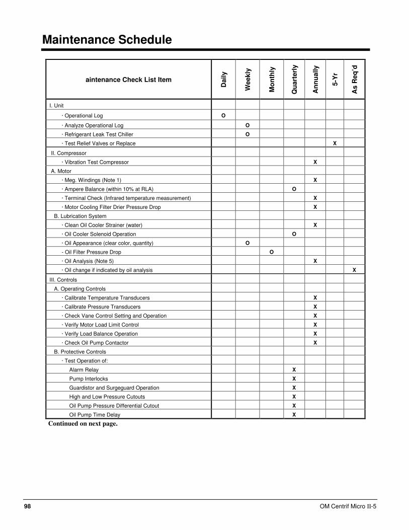
98 OM Centrif Micro ΙΙ-5
Maintenance Schedule
aintenance Check List Item
Daily
Weekly
Mo
nth
ly
Qu
art
erl
y
An
nu
ally
5-Y
r
As R
eq
’d
I. Unit
· Operational Log O
· Analyze Operational Log O
· Refrigerant Leak Test Chiller O
· Test Relief Valves or Replace X
II. Compressor
· Vibration Test Compressor X
A. Motor
· Meg. Windings (Note 1) X
· Ampere Balance (within 10% at RLA) O
· Terminal Check (Infrared temperature measurement) X
· Motor Cooling Filter Drier Pressure Drop X
B. Lubrication System
· Clean Oil Cooler Strainer (water) X
· Oil Cooler Solenoid Operation O
· Oil Appearance (clear color, quantity) O
- Oil Filter Pressure Drop O
· Oil Analysis (Note 5) X
· Oil change if indicated by oil analysis X
III. Controls
A. Operating Controls
· Calibrate Temperature Transducers X
· Calibrate Pressure Transducers X
· Check Vane Control Setting and Operation X
· Verify Motor Load Limit Control X
· Verify Load Balance Operation X
· Check Oil Pump Contactor X
B. Protective Controls
· Test Operation of:
Alarm Relay X
Pump Interlocks X
Guardistor and Surgeguard Operation X
High and Low Pressure Cutouts X
Oil Pump Pressure Differential Cutout X
Oil Pump Time Delay X
Continued on next page.
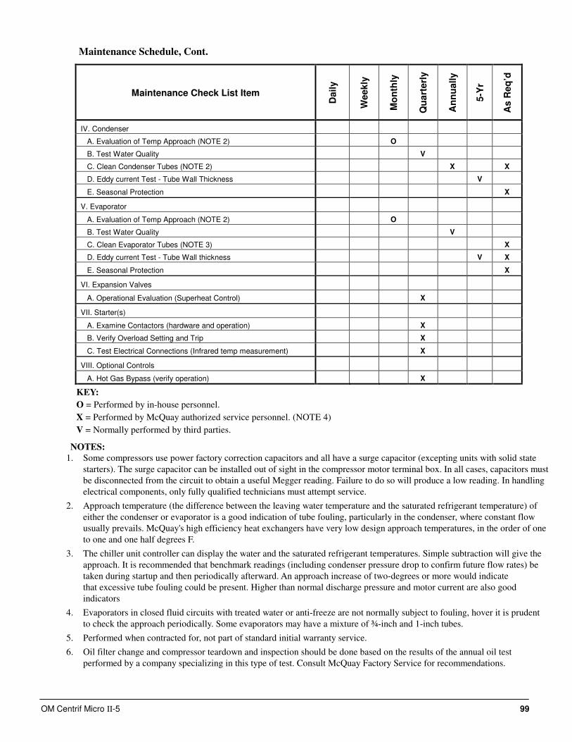
OM Centrif Micro ΙΙ-5 99
Maintenance Schedule, Cont.
Maintenance Check List Item
Daily
Weekly
Mo
nth
ly
Qu
art
erl
y
An
nu
ally
5-Y
r
As R
eq
’d
IV. Condenser
A. Evaluation of Temp Approach (NOTE 2) O
B. Test Water Quality V
C. Clean Condenser Tubes (NOTE 2) X X
D. Eddy current Test - Tube Wall Thickness V
E. Seasonal Protection X
V. Evaporator
A. Evaluation of Temp Approach (NOTE 2) O
B. Test Water Quality V
C. Clean Evaporator Tubes (NOTE 3) X
D. Eddy current Test - Tube Wall thickness V X
E. Seasonal Protection X
VI. Expansion Valves
A. Operational Evaluation (Superheat Control) X
VII. Starter(s)
A. Examine Contactors (hardware and operation) X
B. Verify Overload Setting and Trip X
C. Test Electrical Connections (Infrared temp measurement) X
VIII. Optional Controls
A. Hot Gas Bypass (verify operation) X
KEY:
O = Performed by in-house personnel.
X = Performed by McQuay authorized service personnel. (NOTE 4)
V = Normally performed by third parties.
NOTES:
1. Some compressors use power factory correction capacitors and all have a surge capacitor (excepting units with solid state
starters). The surge capacitor can be installed out of sight in the compressor motor terminal box. In all cases, capacitors must
be disconnected from the circuit to obtain a useful Megger reading. Failure to do so will produce a low reading. In handling
electrical components, only fully qualified technicians must attempt service.
2. Approach temperature (the difference between the leaving water temperature and the saturated refrigerant temperature) of
either the condenser or evaporator is a good indication of tube fouling, particularly in the condenser, where constant flow
usually prevails. McQuay's high efficiency heat exchangers have very low design approach temperatures, in the order of one
to one and one half degrees F.
3. The chiller unit controller can display the water and the saturated refrigerant temperatures. Simple subtraction will give the
approach. It is recommended that benchmark readings (including condenser pressure drop to confirm future flow rates) be
taken during startup and then periodically afterward. An approach increase of two-degrees or more would indicate
that excessive tube fouling could be present. Higher than normal discharge pressure and motor current are also good
indicators
4. Evaporators in closed fluid circuits with treated water or anti-freeze are not normally subject to fouling, hover it is prudent
to check the approach periodically. Some evaporators may have a mixture of ¾-inch and 1-inch tubes.
5. Performed when contracted for, not part of standard initial warranty service.
6. Oil filter change and compressor teardown and inspection should be done based on the results of the annual oil test
performed by a company specializing in this type of test. Consult McQuay Factory Service for recommendations.

(800) 432-1342 • www.mcquay.com OM CentrifMicro II-5 (03/11)
This document contains the most current product information as of this printing. For the most up-to-date product information, please go to www.mcquay.com.
All McQuay equipment is sold pursuant to McQuay’s Standard Terms and Conditions of Sale and Limited Product Warranty. Consult your local McQuay Representative for warranty details. Refer to form 933-43285Y. To find your local representative, go to www.mcquay.com