Mechanism and characteristic of rain-induced vibration...
6
Journal of Mechanical Science and Technology 26 (8) (2012) 2505~2510 www.springerlink.com/content/1738-494x DOI 10.1007/s12206-012-0631-0 Mechanism and characteristic of rain-induced vibration on high-voltage transmission line † Chao Zhou * , Yibing Liu and Xiaoming Rui School of Energy Power and Mechanical Engineering, North China Electric Power University, Beijing 102206, China (Manuscript Received December 3, 2011; Revised March 26, 2012; Accepted March 26, 2012) ---------------------------------------------------------------------------------------------------------------------------------------------------------------------------------------------------------------------------------------------------------------------------------------------- Abstract Under the rainy weather, rain-induced vibration on high-voltage (HV) transmission line often occurs, which intensifies fatigue conduc- tors and tower callapses. Mechanism and control measures of the rain-induced vibration have aroused wide attention in power engineer- ing. The mechanism can be explained that the droplets suspended to the conductors amplify corona discharges with ionic wind, forms non-circular cross-sections, and the rain-induced vibration is due to the coupling action of vortex-induced vibration by ionic wind and galloping vibration by external wind force. Based on the mechanism, a valid model on the rain-induced vibration on high-voltage trans- mission line is proposed based on the finite element theory and the Newmark algorithm. Taking the conductor LGJ-240 as an instance, we investigate the effects of ionic wind and non-circular cross-sections with different parameters on amplitude of the conductors. The result shows non-circular cross-sections have obviously effects, and the ionic wind have a certain influence and easily to coupling with wind force. Mechanism and conclusions in this paper can be used as references to construct High-voltage transmission lines, upgrade the existing lines and control vibration. Keywords: Rain-induced vibration; High-voltage (HV) transmission line; Ionic wind; Galloping ---------------------------------------------------------------------------------------------------------------------------------------------------------------------------------------------------------------------------------------------------------------------------------------------- 1. Introduction In recent years, ultra high voltage (UHV) transmission grid will across wet, rainy southwest regions in China. Under the rainy weather, rain-induced vibration on conductors often occurs, which gives a huge challenge to engineers that how to ensure the safety operation of UHV transmission lines [1-3]. Besides icing galloping and vortex-induced vibration, the rain- induced vibration can else intensify fatigue conductors and eventually lead to the tower collapsed. However, it is difficult to use Den.Hartog or O.Nigol theory to explain the rain- induced vibration phenomenon [4, 5]. Therefore, mechanism and characteristics of the rain-induced vibration urgently need to be studied. In recent years, many experimental studies have done for the different aspects of this subject, researchers point out rain- fall amplifies corona discharges and ionic wind force acting on the conductors can not be ignored [6-8]. Li [9, 10] takes rainfall as a shock load to combine with wind turbulence and establish a rain-wind induced vibration by finite element me- thod. Yamaguchi [11, 12] studies mechanism of rain-induced vibration in cable-stayed bridges, and indicates that rainfall rivulet formed along the upper surface of cable is the origin of rain vibration. However, very few works related to the corona discharges with ionic wind and forms non-circular cross- sections have done to reveal mechanism of the rain-induced vibration on High-voltage transmission line. Base on above reasons, the main objective of the present work is to reveal the mechanism of the rain-induced vibration on the conductors, to validate a rain-induced vibration on the conductors by finite element method and Newmark algorithm. Take LGJ-240 as an instance, we investigate the effects of ionic wind and non-circular cross-sections with different fac- tors on amplitude of the conductors. 2. Mechanism of the rain-induced vibration on HV transmission line The second part consisting of the paper body must be edited in double column format. Figures and tables should be located at top or bottom of either column. Rainfall cause the formation of the droplets on the conductor, and the droplets take a cone shape by electric field. In the heavy rainfall, the droplets form as non-circular cross-sections and flowing along with the con- ductor. Polarized droplets amplify corona discharges with the ionic wind, which flow over the conductor surface and emerge vortex vibration, polarized droplets induce corona discharge * Corresponding author. Tel.: +8601061772297, Fax.: +8601061772297 E-mail address: [email protected] † Recommended by Editor Yeon June Kang © KSME & Springer 2012
Transcript of Mechanism and characteristic of rain-induced vibration...
Journal of Mechanical Science and Technology 26 (8) (2012) 2505~2510
www.springerlink.com/content/1738-494x DOI 10.1007/s12206-012-0631-0
Mechanism and characteristic of rain-induced vibration on high-voltage
transmission line† Chao Zhou*, Yibing Liu and Xiaoming Rui
School of Energy Power and Mechanical Engineering, North China Electric Power University, Beijing 102206, China
(Manuscript Received December 3, 2011; Revised March 26, 2012; Accepted March 26, 2012)
----------------------------------------------------------------------------------------------------------------------------------------------------------------------------------------------------------------------------------------------------------------------------------------------
Abstract Under the rainy weather, rain-induced vibration on high-voltage (HV) transmission line often occurs, which intensifies fatigue conduc-
tors and tower callapses. Mechanism and control measures of the rain-induced vibration have aroused wide attention in power engineer-ing. The mechanism can be explained that the droplets suspended to the conductors amplify corona discharges with ionic wind, forms non-circular cross-sections, and the rain-induced vibration is due to the coupling action of vortex-induced vibration by ionic wind and galloping vibration by external wind force. Based on the mechanism, a valid model on the rain-induced vibration on high-voltage trans-mission line is proposed based on the finite element theory and the Newmark algorithm. Taking the conductor LGJ-240 as an instance, we investigate the effects of ionic wind and non-circular cross-sections with different parameters on amplitude of the conductors. The result shows non-circular cross-sections have obviously effects, and the ionic wind have a certain influence and easily to coupling with wind force. Mechanism and conclusions in this paper can be used as references to construct High-voltage transmission lines, upgrade the existing lines and control vibration.
Keywords: Rain-induced vibration; High-voltage (HV) transmission line; Ionic wind; Galloping ---------------------------------------------------------------------------------------------------------------------------------------------------------------------------------------------------------------------------------------------------------------------------------------------- 1. Introduction
In recent years, ultra high voltage (UHV) transmission grid will across wet, rainy southwest regions in China. Under the rainy weather, rain-induced vibration on conductors often occurs, which gives a huge challenge to engineers that how to ensure the safety operation of UHV transmission lines [1-3]. Besides icing galloping and vortex-induced vibration, the rain-induced vibration can else intensify fatigue conductors and eventually lead to the tower collapsed. However, it is difficult to use Den.Hartog or O.Nigol theory to explain the rain-induced vibration phenomenon [4, 5]. Therefore, mechanism and characteristics of the rain-induced vibration urgently need to be studied.
In recent years, many experimental studies have done for the different aspects of this subject, researchers point out rain-fall amplifies corona discharges and ionic wind force acting on the conductors can not be ignored [6-8]. Li [9, 10] takes rainfall as a shock load to combine with wind turbulence and establish a rain-wind induced vibration by finite element me-thod. Yamaguchi [11, 12] studies mechanism of rain-induced vibration in cable-stayed bridges, and indicates that rainfall
rivulet formed along the upper surface of cable is the origin of rain vibration. However, very few works related to the corona discharges with ionic wind and forms non-circular cross-sections have done to reveal mechanism of the rain-induced vibration on High-voltage transmission line.
Base on above reasons, the main objective of the present work is to reveal the mechanism of the rain-induced vibration on the conductors, to validate a rain-induced vibration on the conductors by finite element method and Newmark algorithm. Take LGJ-240 as an instance, we investigate the effects of ionic wind and non-circular cross-sections with different fac-tors on amplitude of the conductors.
2. Mechanism of the rain-induced vibration on HV
transmission line
The second part consisting of the paper body must be edited in double column format. Figures and tables should be located at top or bottom of either column. Rainfall cause the formation of the droplets on the conductor, and the droplets take a cone shape by electric field. In the heavy rainfall, the droplets form as non-circular cross-sections and flowing along with the con-ductor. Polarized droplets amplify corona discharges with the ionic wind, which flow over the conductor surface and emerge vortex vibration, polarized droplets induce corona discharge
*Corresponding author. Tel.: +8601061772297, Fax.: +8601061772297 E-mail address: [email protected]
† Recommended by Editor Yeon June Kang © KSME & Springer 2012
2506 C. Zhou et al. / Journal of Mechanical Science and Technology 26 (8) (2012) 2505~2510
and ionic wind is summarized as four steps [13, 14] (Fig. 1). (1) Rainfall causes the formation of the droplets on the con-
ductor which takes a cone shape in electric field, and local electric field accumulated at sharp curve radius of droplet tip.
(2) Once the local electric field breakdown gaseous medium, corona discharges with the ionic wind, the ionic wind flows over and induce upward forces on the conductor. Meanwhile, polarized droplets are ejected out of the conductor.
(3) When the conductor at upper position, ionic wind is weakened, electric field diminished and gravity force plays a dominant role, the conductor start moves downward.
(4) When the conductor reached down position, if the rain-fall is sufficient to feed the droplets again and local electric field start appears, the conductor repeats process (1)-(4).
By the action of external wind force, the droplets be divided into upper rain-line and down rain-line, the upper rain-line movement periodic changes cross-sections of the conductor and results in aerodynamic instable. Thus, the vertical move-ment of the HV conductor subjected to external wind and ionic wind could be modeled as Fig. 2, where 0 , , ,U V U
, , , , ,L D G cC C f f γ θ representing external wind velocity, conductor velocity, relative wind velocity, lift coefficient, drag coefficient, gravity force, ionic wind force, attack angle and upper rain-line position angle.
As the mass of rain-line is far less than the mass of the con-ductor, and the ionic wind by upper rain-line discharge is mainly affect horizontal movement, so we neglect the mass of rain-line and the ionic wind by upper rain-line discharge. Based on the assumptions given above, the equation of rain-
induced vibration on the conductor takes the following form.
2 2
2
2 ( ) / ( )sin
( )cos /y y y c g L
D
y y y f f m U r C
U r C m
ξ ω ω ρ γ θ γ
ρ γ θ γ
+ + = − − − −
− − (1)
c ionic lf U rCρ= (2)
where y is the vertical displacement of the conductor in mo-tion plane (Fig. 2), yξ is the structural damping ratio, yω is the conductor circular frequency, m denotes the mass of the conductor per unit length, r is the radius of the conductor, ρ is the fluid density, ionicU is the velocity of the ionic wind and lC is lift coefficient of ionic wind.
Firstly we fit the lift and drag coefficient in Eq. (1) with re-spect to γ θ− , and ,L DC C are expressed as polynomial function based experimental data come from Ref. [15]. Given the conductor with properties that 045γ = , 9.12 /U m s= 1.048 / 2 1.919π γ θ≤ + − ≤ , and the polynomial functions of
,L DC C as following.
3 2
3 2
( ) 77.11 - 366.18 + 562.73 - 276.12
( ) 10.16 - 48.06 + 73.56 - 35.83( / 2 )
L
D
C
C
ϑ ϑ ϑ ϑ
ϑ ϑ ϑ ϑϑ π γ θ
⎧ =⎪⎨
=⎪⎩= + −
(3)
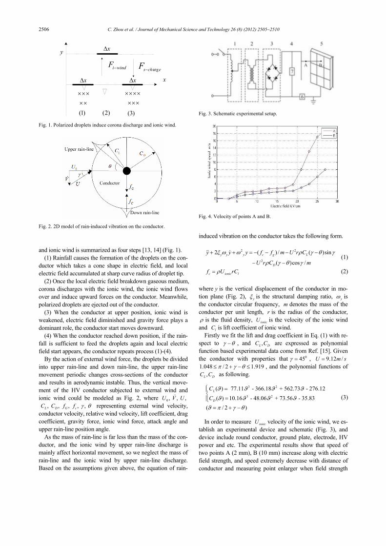
In order to measure ionicU velocity of the ionic wind, we es-
tablish an experimental device and schematic (Fig. 3), and device include round conductor, ground plate, electrode, HV power and etc. The experimental results show that speed of two points A (2 mm), B (10 mm) increase along with electric field strength, and speed extremely decrease with distance of conductor and measuring point enlarger when field strength
x
y
×××××××
i windF −
×××××
)1( )2( )3(
xΔ
xΔ
xΔ
echsF arg−
Fig. 1. Polarized droplets induce corona discharge and ionic wind.
Fig. 2. 2D model of rain-induced vibration on the conductor.
Fig. 3. Schematic experimental setup.
Fig. 4. Velocity of points A and B.
C. Zhou et al. / Journal of Mechanical Science and Technology 26 (8) (2012) 2505~2510 2507
exceeding 20 KV/cm (Fig. 4). For the reason that spectrum of full corona discharge is 100-
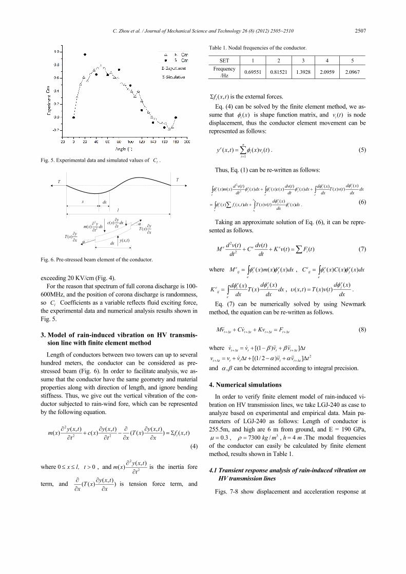
600MHz, and the position of corona discharge is randomness, so lC Coefficients as a variable reflects fluid exciting force, the experimental data and numerical analysis results shown in Fig. 5.
3. Model of rain-induced vibration on HV transmis-
sion line with finite element method
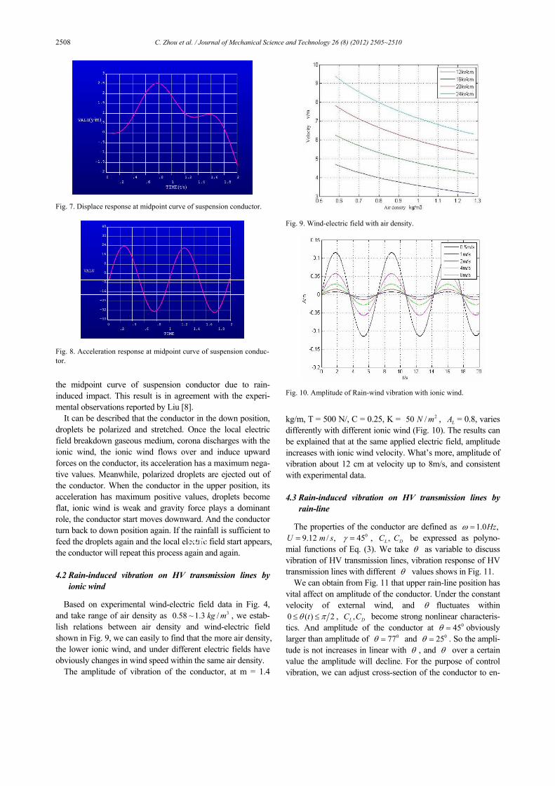
Length of conductors between two towers can up to several hundred meters, the conductor can be considered as pre-stressed beam (Fig. 6). In order to facilitate analysis, we as-sume that the conductor have the same geometry and material properties along with direction of length, and ignore bending stiffness. Thus, we give out the vertical vibration of the con-ductor subjected to rain-wind fore, which can be represented by the following equation.
2
2 2
( , ) ( , ) ( , )( ) ( ) ( ( ) ) ( , )iy x t y x t y x tm x c x T x f x t
t t x x∂ ∂ ∂ ∂
+ − = Σ∂ ∂ ∂ ∂
(4)
where 0 0x l t≤ ≤ >, , and2
2
( , )( ) y x tm xt
∂∂
is the inertia fore
term, and ( , )( ( ) )y x tT xx x∂ ∂∂ ∂
is tension force term, and
( , )if x tΣ is the external forces. Eq. (4) can be solved by the finite element method, we as-
sume that ( )i xφ is shape function matrix, and ( )iv t is node displacement, thus the conductor element movement can be represented as follows:
1( , ) ( ) ( ) .
ne
i ii
y x t x v tφ=
=∑ (5)
Thus, Eq. (1) can be re-written as follows:
2
2
( )( ) ( ) ( )( ) ( ) ( ) ( ) ( ) ( ) ( ) ( )eeje e e e i
i j i je e e
d xd v t dv t d xx m x x dx x c x x dx T x v t dxdt dt dx dx
φφφ φ φ φ+ +∫ ∫ ∫
1
( )( ) ( , ) ( ) ( ) ( ) .
nx eje e
i i ie x
d xx f x t dx T x v t x dx
dxφ
φ φ= +∑∫ ∫ (6)
Taking an approximate solution of Eq. (6), it can be repre-
sented as follows.
2
2
( ) ( ) ( ) ( )e e ei
d v t dv tM C K v t F tdt dt
+ + =∑ (7)
where ( ) ( ) ( )e e e
ij i je
M x m x x dxφ φ= ∫ , ( ) ( ) ( )e e eij i j
e
C x C x x dxφ φ= ∫
( )( ) ( )eeje i
ije
d xd xK T x dxdx dx
φφ= ∫ ,
( )( , ) ( ) ( ) .
ejd x
x t T x v tdxφ
υ =
Eq. (7) can be numerically solved by using Newmark method, the equation can be re-written as follows.
t t t t t t t tMv Cv Kv F+Δ +Δ +Δ +Δ+ + = (8)
where [(1 ) ]t t t t t tv v v v tβ β+Δ +Δ= + − + Δ
2[(1/ 2 ) ]t t t t t t tv v v t v v tα α+Δ +Δ= + Δ + − + Δ and ,α β can be determined according to integral precision.
4. Numerical simulations
In order to verify finite element model of rain-induced vi-bration on HV transmission lines, we take LGJ-240 as case to analyze based on experimental and empirical data. Main pa-rameters of LGJ-240 as follows: Length of conductor is 255.5m, and high are 6 m from ground, and E = 190 GPa,
0.3μ = , 37300 /kg mρ = , 4h m= .The modal frequencies of the conductor can easily be calculated by finite element method, results shown in Table 1.
4.1 Transient response analysis of rain-induced vibration on
HV transmission lines
Figs. 7-8 show displacement and acceleration response at
Fig. 5. Experimental data and simulated values of lC .
T T
x dx
l
dx
( ) yc x dxt∂∂
2
2( ) ym x dxt
∂∂ ( ) yT x
x∂∂
( ) yT xx∂∂ ( , )y x t
α
α
Fig. 6. Pre-stressed beam element of the conductor.
Table 1. Nodal frequencies of the conductor.
SET 1 2 3 4 5 Frequency
/Hz 0.69551 0.81521 1.3928 2.0959 2.0967
2508 C. Zhou et al. / Journal of Mechanical Science and Technology 26 (8) (2012) 2505~2510
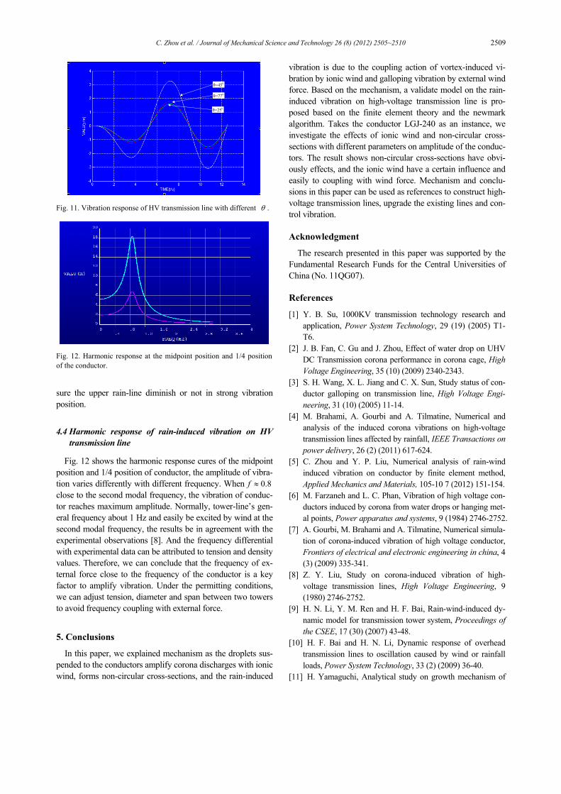
the midpoint curve of suspension conductor due to rain-induced impact. This result is in agreement with the experi-mental observations reported by Liu [8].
It can be described that the conductor in the down position, droplets be polarized and stretched. Once the local electric field breakdown gaseous medium, corona discharges with the ionic wind, the ionic wind flows over and induce upward forces on the conductor, its acceleration has a maximum nega-tive values. Meanwhile, polarized droplets are ejected out of the conductor. When the conductor in the upper position, its acceleration has maximum positive values, droplets become flat, ionic wind is weak and gravity force plays a dominant role, the conductor start moves downward. And the conductor turn back to down position again. If the rainfall is sufficient to feed the droplets again and the local electric field start appears, the conductor will repeat this process again and again.
4.2 Rain-induced vibration on HV transmission lines by
ionic wind
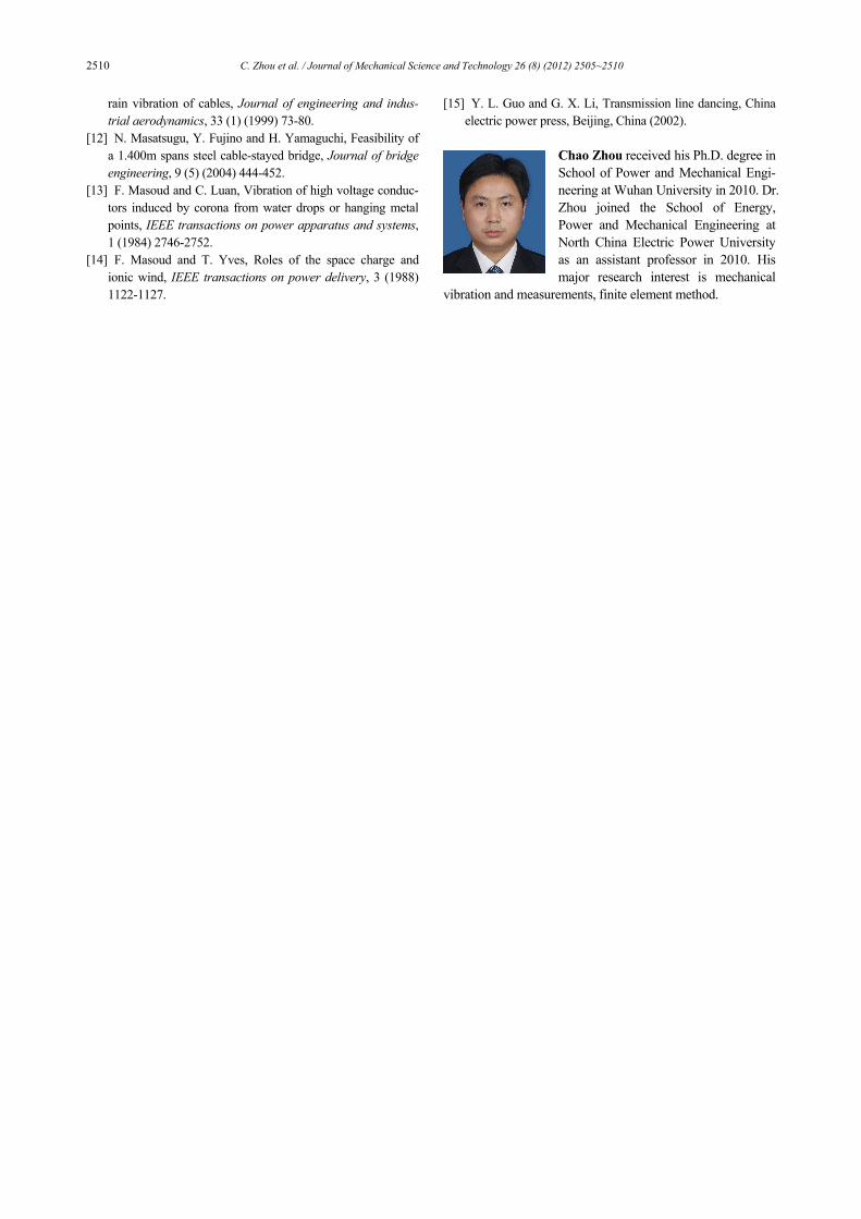
Based on experimental wind-electric field data in Fig. 4, and take range of air density as 30.58 ~ 1.3 /kg m , we estab-lish relations between air density and wind-electric field shown in Fig. 9, we can easily to find that the more air density, the lower ionic wind, and under different electric fields have obviously changes in wind speed within the same air density.
The amplitude of vibration of the conductor, at m = 1.4
kg/m, T = 500 N/, C = 0.25, K = 250 /N m , LA = 0.8, varies differently with different ionic wind (Fig. 10). The results can be explained that at the same applied electric field, amplitude increases with ionic wind velocity. What’s more, amplitude of vibration about 12 cm at velocity up to 8m/s, and consistent with experimental data.
4.3 Rain-induced vibration on HV transmission lines by
rain-line
The properties of the conductor are defined as 1.0 ,Hzω = 09.12 / , 45U m s γ= = , ,L DC C be expressed as polyno-
mial functions of Eq. (3). We take θ as variable to discuss vibration of HV transmission lines, vibration response of HV transmission lines with different θ values shows in Fig. 11.
We can obtain from Fig. 11 that upper rain-line position has vital affect on amplitude of the conductor. Under the constant velocity of external wind, and θ fluctuates within 0 ( ) 2tθ π≤ ≤ , ,L DC C become strong nonlinear characteris-tics. And amplitude of the conductor at 045θ = obviously larger than amplitude of 077θ = and 025θ = . So the ampli-tude is not increases in linear with θ , and θ over a certain value the amplitude will decline. For the purpose of control vibration, we can adjust cross-section of the conductor to en-
Fig. 7. Displace response at midpoint curve of suspension conductor.
Fig. 8. Acceleration response at midpoint curve of suspension conduc-tor.
Fig. 9. Wind-electric field with air density.
Fig. 10. Amplitude of Rain-wind vibration with ionic wind.
C. Zhou et al. / Journal of Mechanical Science and Technology 26 (8) (2012) 2505~2510 2509
sure the upper rain-line diminish or not in strong vibration position.
4.4 Harmonic response of rain-induced vibration on HV
transmission line
Fig. 12 shows the harmonic response cures of the midpoint position and 1/4 position of conductor, the amplitude of vibra-tion varies differently with different frequency. When 0.8f ≈ close to the second modal frequency, the vibration of conduc-tor reaches maximum amplitude. Normally, tower-line’s gen-eral frequency about 1 Hz and easily be excited by wind at the second modal frequency, the results be in agreement with the experimental observations [8]. And the frequency differential with experimental data can be attributed to tension and density values. Therefore, we can conclude that the frequency of ex-ternal force close to the frequency of the conductor is a key factor to amplify vibration. Under the permitting conditions, we can adjust tension, diameter and span between two towers to avoid frequency coupling with external force.
5. Conclusions
In this paper, we explained mechanism as the droplets sus-pended to the conductors amplify corona discharges with ionic wind, forms non-circular cross-sections, and the rain-induced
vibration is due to the coupling action of vortex-induced vi-bration by ionic wind and galloping vibration by external wind force. Based on the mechanism, a validate model on the rain-induced vibration on high-voltage transmission line is pro-posed based on the finite element theory and the newmark algorithm. Takes the conductor LGJ-240 as an instance, we investigate the effects of ionic wind and non-circular cross-sections with different parameters on amplitude of the conduc-tors. The result shows non-circular cross-sections have obvi-ously effects, and the ionic wind have a certain influence and easily to coupling with wind force. Mechanism and conclu-sions in this paper can be used as references to construct high-voltage transmission lines, upgrade the existing lines and con-trol vibration.
Acknowledgment
The research presented in this paper was supported by the Fundamental Research Funds for the Central Universities of China (No. 11QG07).
References
[1] Y. B. Su, 1000KV transmission technology research and application, Power System Technology, 29 (19) (2005) T1-T6.
[2] J. B. Fan, C. Gu and J. Zhou, Effect of water drop on UHV DC Transmission corona performance in corona cage, High Voltage Engineering, 35 (10) (2009) 2340-2343.
[3] S. H. Wang, X. L. Jiang and C. X. Sun, Study status of con-ductor galloping on transmission line, High Voltage Engi-neering, 31 (10) (2005) 11-14.
[4] M. Brahami, A. Gourbi and A. Tilmatine, Numerical and analysis of the induced corona vibrations on high-voltage transmission lines affected by rainfall, IEEE Transactions on power delivery, 26 (2) (2011) 617-624.
[5] C. Zhou and Y. P. Liu, Numerical analysis of rain-wind induced vibration on conductor by finite element method, Applied Mechanics and Materials, 105-10 7 (2012) 151-154.
[6] M. Farzaneh and L. C. Phan, Vibration of high voltage con-ductors induced by corona from water drops or hanging met-al points, Power apparatus and systems, 9 (1984) 2746-2752.
[7] A. Gourbi, M. Brahami and A. Tilmatine, Numerical simula-tion of corona-induced vibration of high voltage conductor, Frontiers of electrical and electronic engineering in china, 4 (3) (2009) 335-341.
[8] Z. Y. Liu, Study on corona-induced vibration of high-voltage transmission lines, High Voltage Engineering, 9 (1980) 2746-2752.
[9] H. N. Li, Y. M. Ren and H. F. Bai, Rain-wind-induced dy-namic model for transmission tower system, Proceedings of the CSEE, 17 (30) (2007) 43-48.
[10] H. F. Bai and H. N. Li, Dynamic response of overhead transmission lines to oscillation caused by wind or rainfall loads, Power System Technology, 33 (2) (2009) 36-40.
[11] H. Yamaguchi, Analytical study on growth mechanism of
0θ=77
0θ=25
0θ=45
Fig. 11. Vibration response of HV transmission line with different θ .
Fig. 12. Harmonic response at the midpoint position and 1/4 positionof the conductor.
2510 C. Zhou et al. / Journal of Mechanical Science and Technology 26 (8) (2012) 2505~2510
rain vibration of cables, Journal of engineering and indus-trial aerodynamics, 33 (1) (1999) 73-80.
[12] N. Masatsugu, Y. Fujino and H. Yamaguchi, Feasibility of a 1.400m spans steel cable-stayed bridge, Journal of bridge engineering, 9 (5) (2004) 444-452.
[13] F. Masoud and C. Luan, Vibration of high voltage conduc-tors induced by corona from water drops or hanging metal points, IEEE transactions on power apparatus and systems, 1 (1984) 2746-2752.
[14] F. Masoud and T. Yves, Roles of the space charge and ionic wind, IEEE transactions on power delivery, 3 (1988) 1122-1127.
[15] Y. L. Guo and G. X. Li, Transmission line dancing, China electric power press, Beijing, China (2002).
Chao Zhou received his Ph.D. degree in School of Power and Mechanical Engi-neering at Wuhan University in 2010. Dr. Zhou joined the School of Energy, Power and Mechanical Engineering at North China Electric Power University as an assistant professor in 2010. His major research interest is mechanical
vibration and measurements, finite element method.