MECHANICS OF MATERIALS REVIEW - Missouri S&T - …web.mst.edu/~chiep/FE Review Files/Mec… ·...
42
1 MECHANICS OF MATERIALS REVIEW Notation: 01/25/22
Transcript of MECHANICS OF MATERIALS REVIEW - Missouri S&T - …web.mst.edu/~chiep/FE Review Files/Mec… ·...
1
MECHANICS OF MATERIALS REVIEW
Notation:
05/06/23
2
- normal stress (psi or Pa)- shear stress (psi or Pa) - normal strain (in/in or m/m)γ - shearing strain (in/in or m/m)I - area moment of inertia (in4 or m4)J - polar area moment
of inertia (in4 or m4)N - revolutions per minuteE - modulus of elasticity (psi or Pa)G - modulus of rigidity (psi or Pa)
- Poisson’s ratio - coefficient of thermal expansion
(/°F or /°C)M - bending moment in beamsT - torque in shaftsT - temperature change (F or C)hp - horsepower (1 hp = 550 ft-lb/sec)F.S. - factor of safety = t = T - thermal strain
Section 1: Introduction
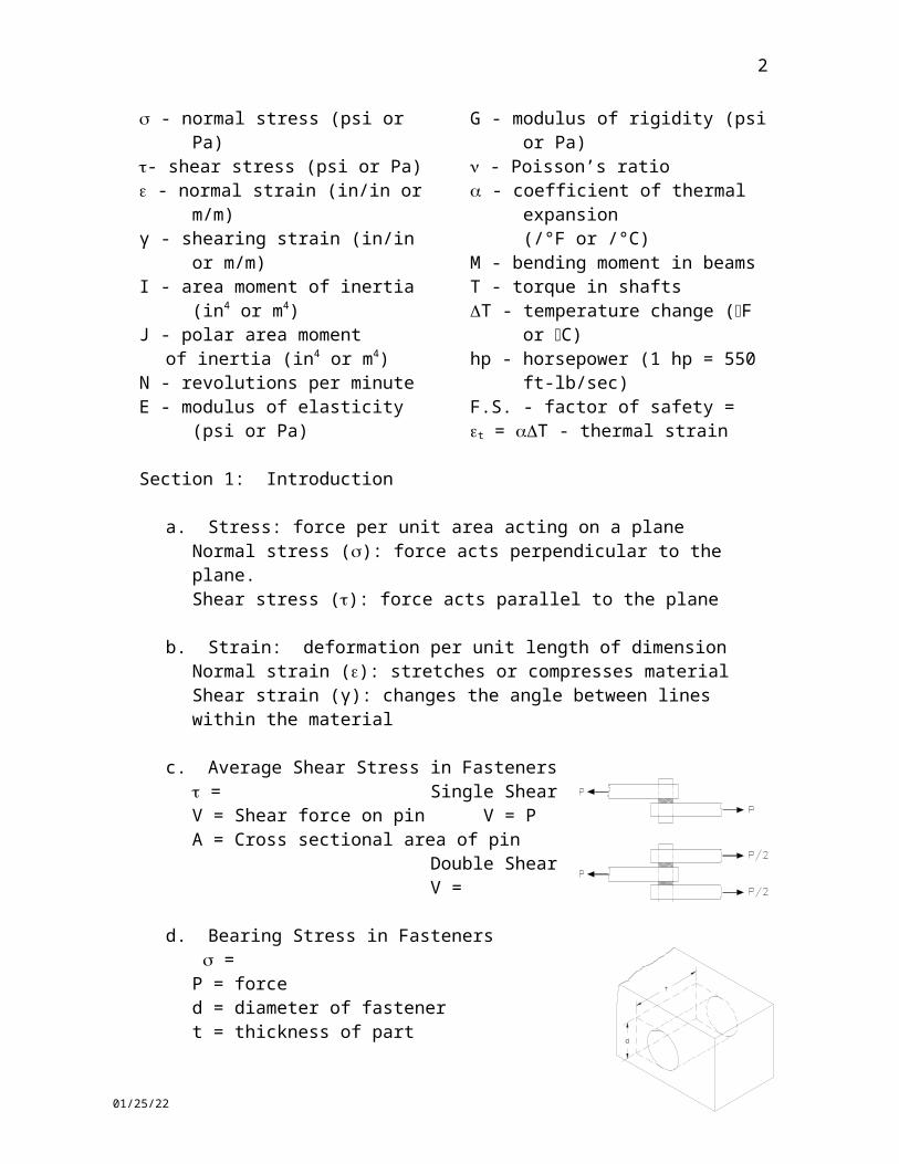
a. Stress: force per unit area acting on a planeNormal stress (): force acts perpendicular to the plane.Shear stress (): force acts parallel to the plane
b. Strain: deformation per unit length of dimensionNormal strain (): stretches or compresses materialShear strain (γ): changes the angle between lines within the material
c. Average Shear Stress in Fasteners = Single ShearV = Shear force on pin V = PA = Cross sectional area of pin
Double ShearV =
d. Bearing Stress in Fasteners = P = forced = diameter of fastenert = thickness of part
05/06/23
3
Section 2: Axial Loading
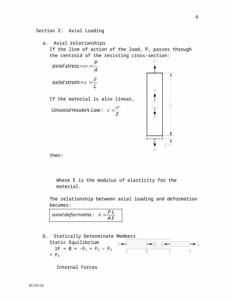
a. Axial relationshipsIf the line of action of the load, P, passes through the centroid of the resisting cross-section:
If the material is also linear, then:
Where E is the modulus of elasticity for the material.
The relationship between axial loading and deformation becomes:
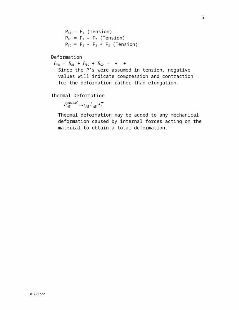
b. Statically Determinate MembersStatic Equilibrium F = 0 = -F1 + F2 – F3 + F4
Internal ForcesPAB = F1 (Tension)PBC = F1 – F2 (Tension)PCD = F1 – F2 + F3 (Tension)
Deformation δAD = δAB + δBC + δCD = + +
Since the P’s were assumed in tension, negative values will indicate compression and contraction for the deformation rather than elongation.
Thermal Deformation
Thermal deformation may be added to any mechanical deformation caused by internal forces acting on the material to obtain a total deformation.
05/06/23
4
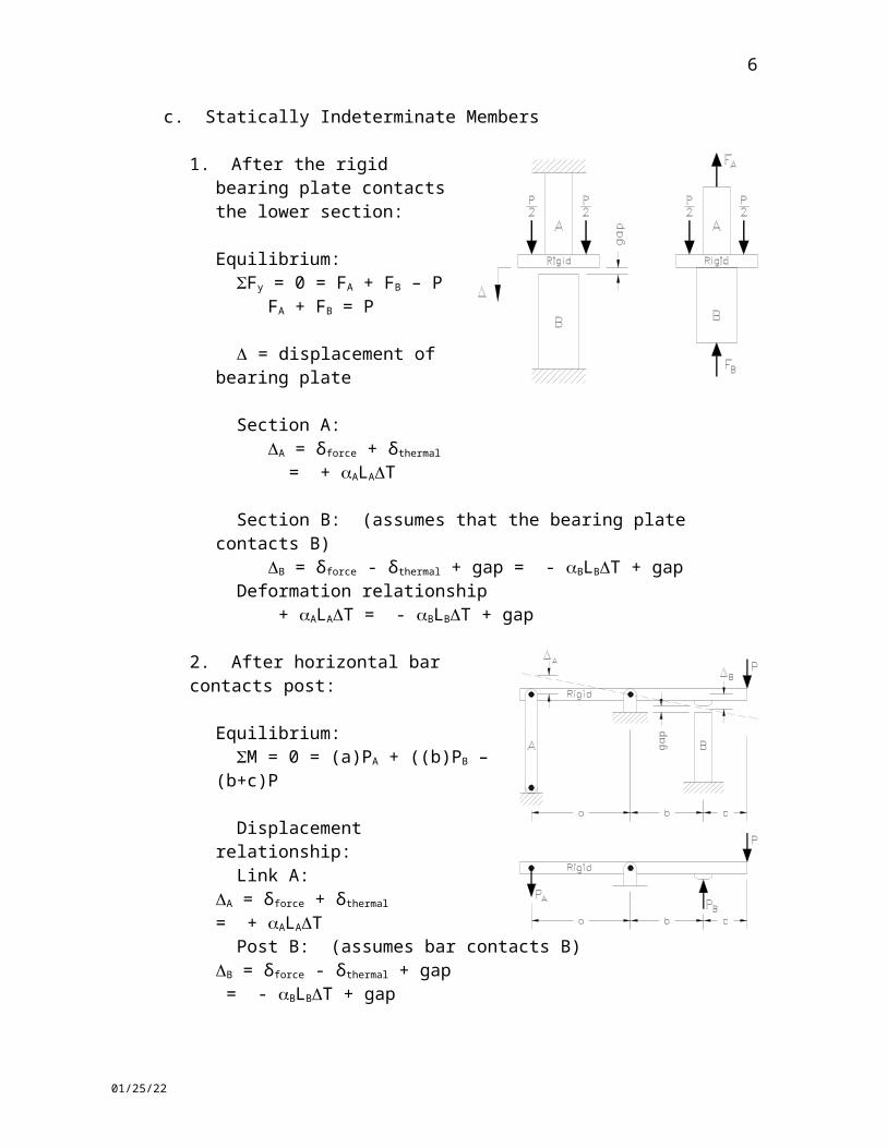
c. Statically Indeterminate Members
1. After the rigid bearing plate contacts the lower section:
Equilibrium: Fy = 0 = FA + FB – P
FA + FB = P
= displacement of bearing plate
Section A:A = δforce + δthermal
= + ALAT
Section B: (assumes that the bearing plate contacts B)B = δforce - δthermal + gap = - BLBT + gap
Deformation relationship + ALAT = - BLBT + gap
2. After horizontal bar contacts post:
Equilibrium: M = 0 = (a)PA + ((b)PB – (b+c)P
Displacement relationship: Link A:A = δforce + δthermal
= + ALAT Post B: (assumes bar contacts B)B = δforce - δthermal + gap = - BLBT + gap
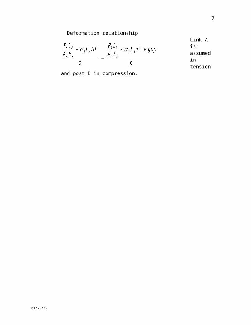
Deformation relationship
Link A is assumed in tension and post B
in compression.
05/06/23
Section 3: Torsion of Circular Sections
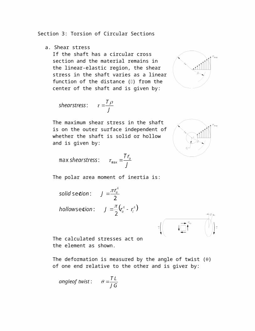
a. Shear stressIf the shaft has a circular cross section and the material remains in the linear-elastic region, the shear stress in the shaft varies as a linear function of the distance () from the center of the shaft and is given by:
The maximum shear stress in the shaft is on the outer surface independent of whether the shaft is solid or hollow and is given by:
The polar area moment of inertia is:
The calculated stresses act on the element as shown.
The deformation is measured by the angle of twist () of one end relative to the other and is giver by:
where G is the modulus of rigidity for the material and L is the length of shaft.
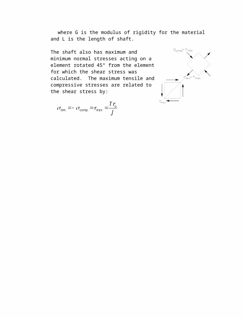
The shaft also has maximum and minimum normal stresses acting on a element rotated 45° from the element for which the shear stress was calculated. The maximum tensile and compressive stresses are related to the shear stress by:
Section 4: Beams
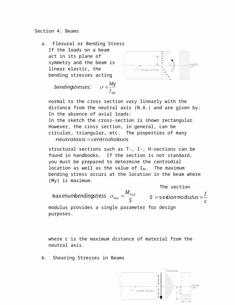
a. Flexural or Bending StressIf the loads on a beam act in its plane of symmetry and the beam is linear elastic, the bending stresses acting normal to the cross section vary linearly with the distance from the neutral axis (N.A.) and are given by:
In the absence of axial loads:
In the sketch the cross-section is shown rectangular. However, the cross section, in general, can be circular, triangular, etc. The properties of many structural sections such as T-, I-, H-sections can be found in handbooks. If the section is not standard, you must be prepared to determine the centrodial location as well as the value of INA. The maximum bending stress occurs at the location in the beam where (My) is maximum.The section modulus provides a single parameter for design purposes.
where c is the maximum distance of material from the neutral axis.
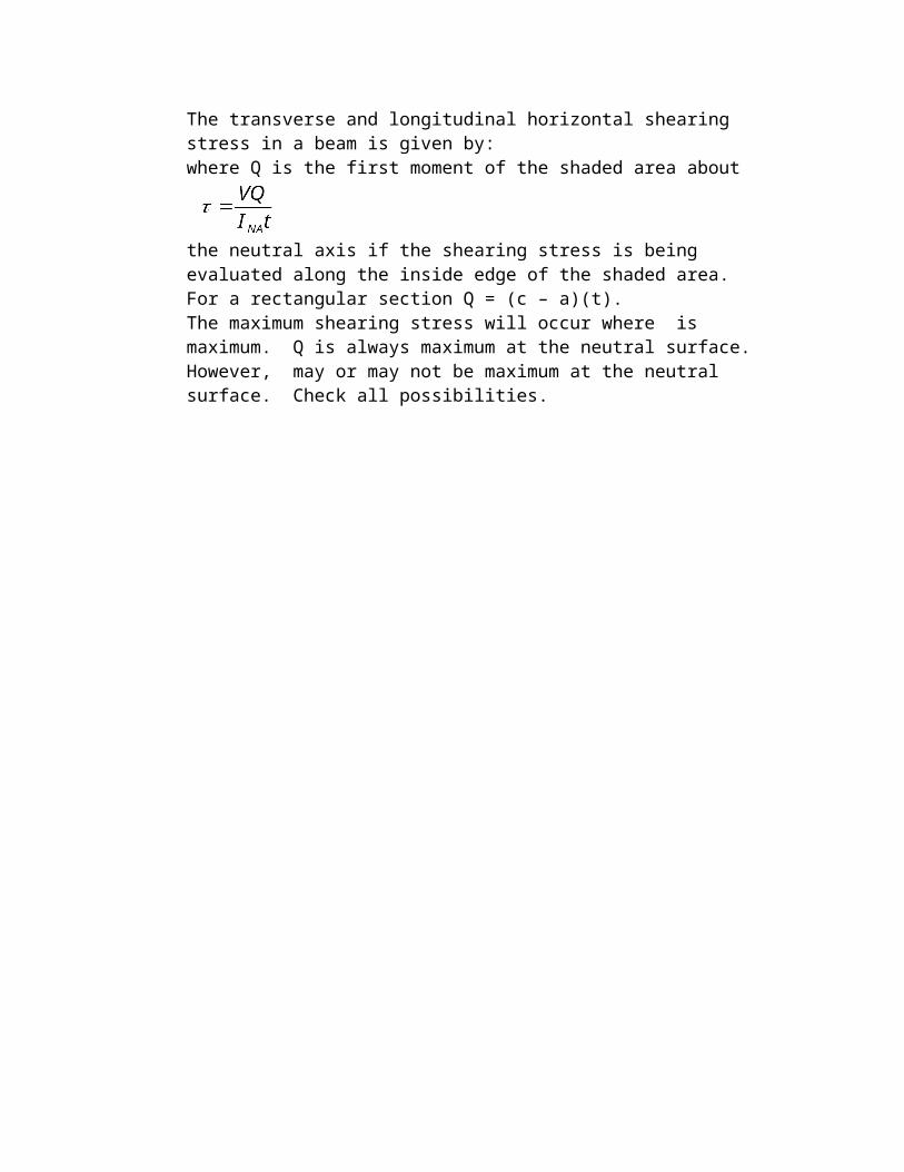
b. Shearing Stresses in Beams
The transverse and longitudinal horizontal shearing stress in a beam is given by:
where Q is the first moment of the shaded area about the neutral axis if the shearing stress is being evaluated along the inside edge of the shaded area. For a rectangular section Q = (c – a)(t).The maximum shearing stress will occur where is maximum. Q is always maximum at the neutral surface. However, may or may not be maximum at the neutral surface. Check all possibilities.

The shear flow or force per unit length of beam acting on the joint between sections making up a built-up cross-section is given by:
where the area on either side of the joint is used to calculate Q.Shear flow and discrete fastener strength are related by: FV = fs, where FV is the net shearing strength of the joint fasteners on a single cross-section of the beam and s is the distance along the beam between cross-sections containing fasteners.
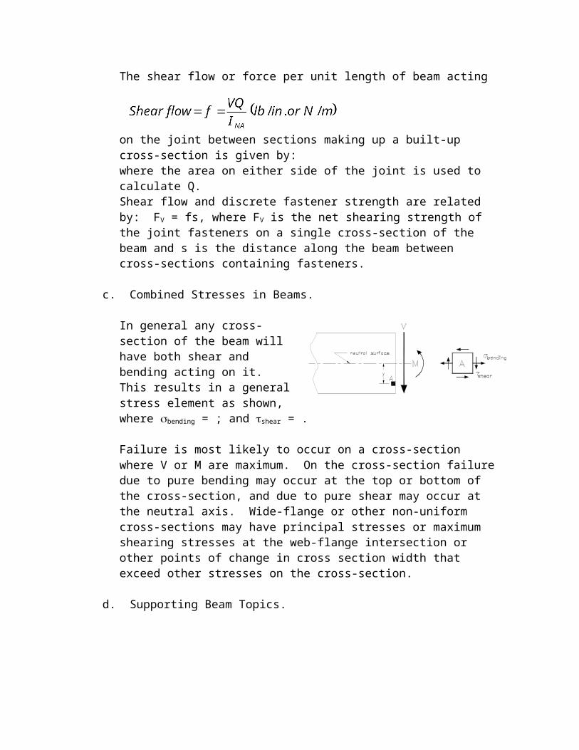
c. Combined Stresses in Beams.
In general any cross-section of the beam will have both shear and bending acting on it. This results in a general stress element as shown,where bending = ; and shear = .
Failure is most likely to occur on a cross-section where V or M are maximum. On the cross-section failure due to pure bending may occur at the top or bottom of the cross-section, and due to pure shear may occur at the neutral axis. Wide-flange or other non-uniform cross-sections may have principal stresses or maximum shearing stresses at the web-flange intersection or other points of change in cross section width that exceed other stresses on the cross-section.
d. Supporting Beam Topics.
Maximum shear and bending moment values are found most easily and reliably using the Shear and Bending Moment Diagrams developed in Statics.
The centroidal location can be determined by first moments about any axis parallel to the bending moment axis.
where A is the entire area of the cross-section and the Ai are the areas of subfigures making up the cross-section. y and the yi's are the perpendicular distance from the reference axis to the centroid of the associated area.
If the cross-section can be divided into common shaped areas for which the location of the centroid and the area moment of inertia (Ii) about the centroid are known then the area moment of inertia (INA) for the cross-section can be determined from:
where the Ii are the area moments of inertia of the individual areas about their own centrodial axis and d is the perpendicular distance between the area centrodial axis and
the neutral axis of the cross-section.
e. Beam Deflections
Two Integration MethodThe deflection of straight beams is determined from the equation:
Here y(x) is the lateral displacement of the beam from its original position as a function of position along the beam, the primes denote derivatives with respect to x, and M(x) is the bending moment as a function of position along the beam. Integration of this equation once yields the equation of the slope as a function of position along the beam:
A second integration yields the deflection or elastic curve equation:
The two integration constants C1 and C2 are evaluated using the boundary conditions imposed on the slope and deflection by the supports.
The majority of beam loading requires that the bending moment be defined using more than one analytic function. Each function is valid over its own portion of the beam length and results in its own set of slope and deflection equations that are valid in that portion of the beam. Each set of equations has its own pair of integration constants. The additional boundary conditions come from requiring that the slope and deflection given by the equations on both sides of a boundary between changes in bending moment functions give the same value when evaluated at the boundary.
Superposition MethodThe solutions for these equations for many different types of supports and loads are given in many of the common engineering handbooks. The principal of superposition allows the solutions of different loads to be added together to give the solution for the combined loads. The limitations of this method depend on how extensive the available beam tables are. It must be kept in mind that the table entry must be able to exactly match the portion of the load being represented using only a scaling factor and/or mirror imaging. Loads in the tables may have either positive or negative values.
Section 5: Thin-Walled Pressure Vessels
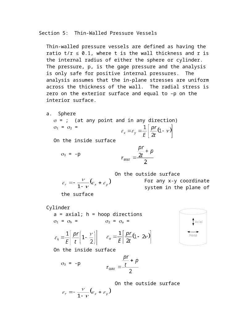
Thin-walled pressure vessels are defined as having the ratio t/r ≤ 0.1, where t is the wall thickness and r is the internal radius of either the sphere or cylinder. The pressure, p, is the gage pressure and the analysis is only safe for positive internal pressures. The analysis assumes that the in-plane stresses are uniform across the thickness of the wall. The radial stress is zero on the exterior surface and equal to –p on the interior surface.
a. Sphere = ; (at any point and in any direction)1 = 2 =
On the inside surface
3 = -p
On the outside surfaceFor any x-y coordinate system in the plane of the surface
Cylindera = axial; h = hoop directions1 = h = 2 = a = On the inside surface
3 = -p
On the outside surfaceFor any x-y coordinate system in the plane of the surface, usually the axial and hoop directions.

Section 6: Column Buckling
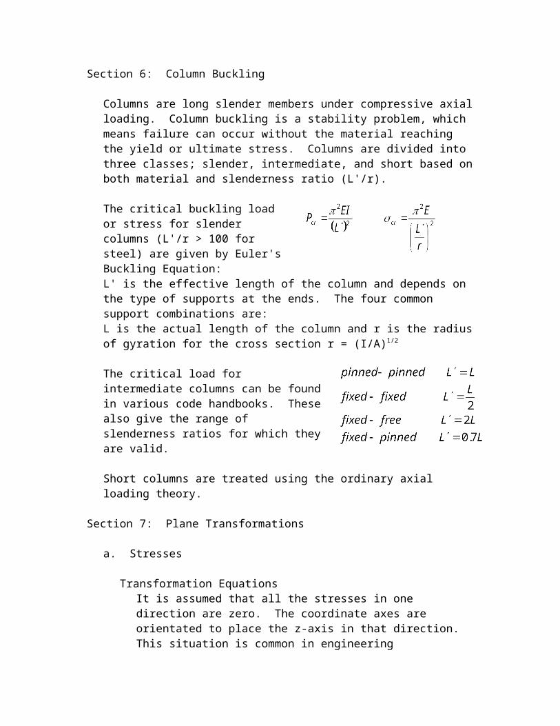
Columns are long slender members under compressive axial loading. Column buckling is a stability problem, which means failure can occur without the material reaching the yield or ultimate stress. Columns are divided into three classes; slender, intermediate, and short based on both material and slenderness ratio (L'/r).
The critical buckling load or stress for slender columns (L'/r > 100 for steel) are given by Euler's Buckling Equation:L' is the effective length of the column and depends on the type of supports at the ends. The four common support combinations are:L is the actual length of the column and r is the radius of gyration for the cross section r = (I/A)1/2
The critical load for intermediate columns can be found in various code handbooks. These also give the range of slenderness ratios for which they are valid.
Short columns are treated using the ordinary axial loading theory.
Section 7: Plane Transformations
a. Stresses
Transformation EquationsIt is assumed that all the stresses in one direction are zero. The coordinate axes are orientated to place the z-axis in that direction. This situation is common in engineering applications. A free surface is the classic example.
The stresses representing the state of stress at a point are different when measured with respect to two different coordinate systems that are rotated with respect to each other. If the first system is labeled xy then the x'y' is rotated counter-clockwise by an angle .
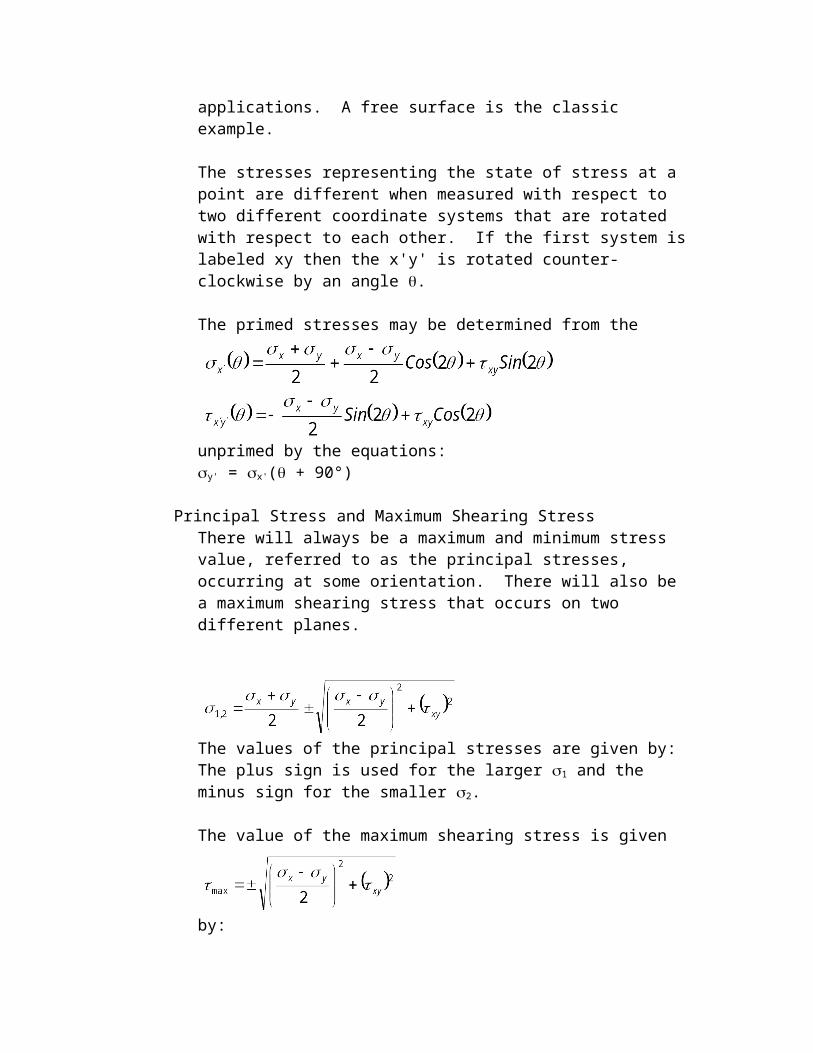
The primed stresses may be determined from the unprimed by the equations:
y' = x'( + 90°)
Principal Stress and Maximum Shearing Stress
There will always be a maximum and minimum stress value, referred to as the principal stresses, occurring at some orientation. There will also be a maximum shearing stress that occurs on two different planes.
The values of the principal stresses are given by:
The plus sign is used for the larger 1 and the minus sign for the smaller 2.
The value of the maximum shearing stress is given by:
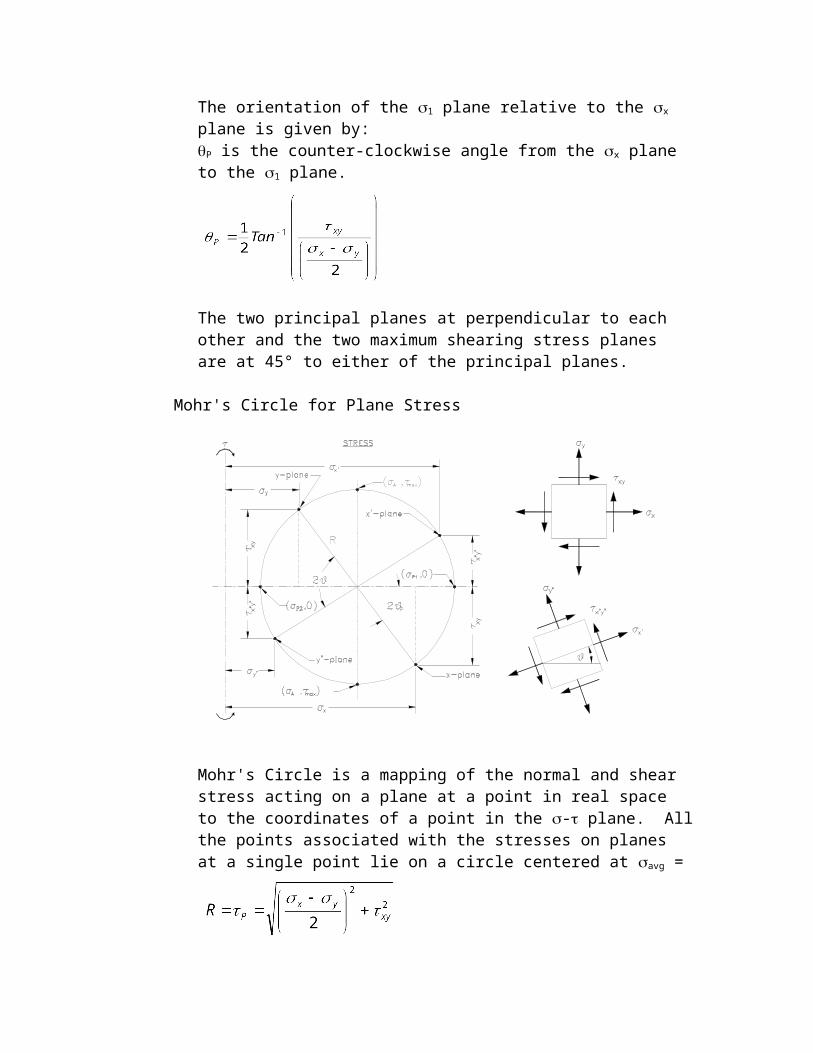
The orientation of the 1 plane relative to the x plane is given by:
P is the counter-clockwise angle from the x plane to the 1 plane.
The two principal planes at perpendicular to each other and the two maximum shearing stress planes are at 45° to either of the principal planes.
Mohr's Circle for Plane Stress
Mohr's Circle is a mapping of the normal and shear stress acting on a plane at a point in real space to the coordinates of a point in the - plane. All the points associated with the stresses on planes at a single point lie on a circle

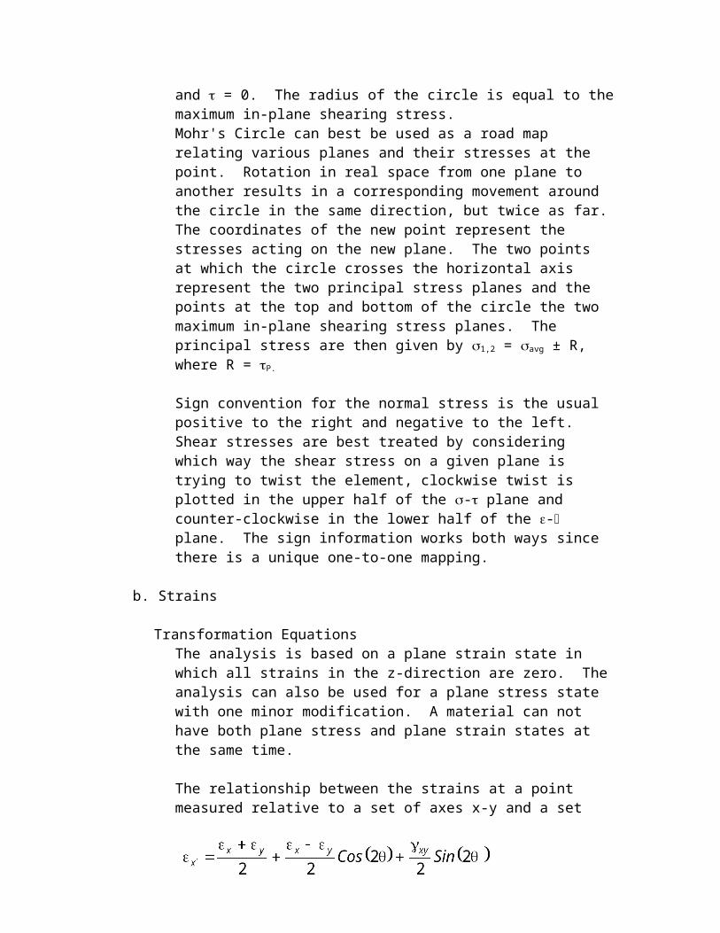
centered at avg = and = 0. The radius of the circle is equal to the maximum in-plane shearing stress.Mohr's Circle can best be used as a road map relating various planes and their stresses at the point. Rotation in real space from one plane to another results in a corresponding movement around the circle in the same direction, but twice as far. The coordinates of the new point represent the stresses acting on the new plane. The two points at which the circle crosses the horizontal axis represent the two principal stress planes and the points at the top and bottom of the circle the two maximum in-plane shearing stress planes. The principal stress are then given by 1,2 = avg ± R, where R = P.
Sign convention for the normal stress is the usual positive to the right and negative to the left. Shear stresses are best treated by considering which way the shear stress on a given plane is trying to twist the element, clockwise twist is plotted in the upper half of the - plane and counter-clockwise in the lower half of the - plane. The sign information works both ways since there is a unique one-to-one mapping.
b. Strains
Transformation EquationsThe analysis is based on a plane strain state in which all strains in the z-direction are zero. The analysis can also be used for a plane stress state with one minor modification. A material can not have both plane stress and plane strain states at the same time.
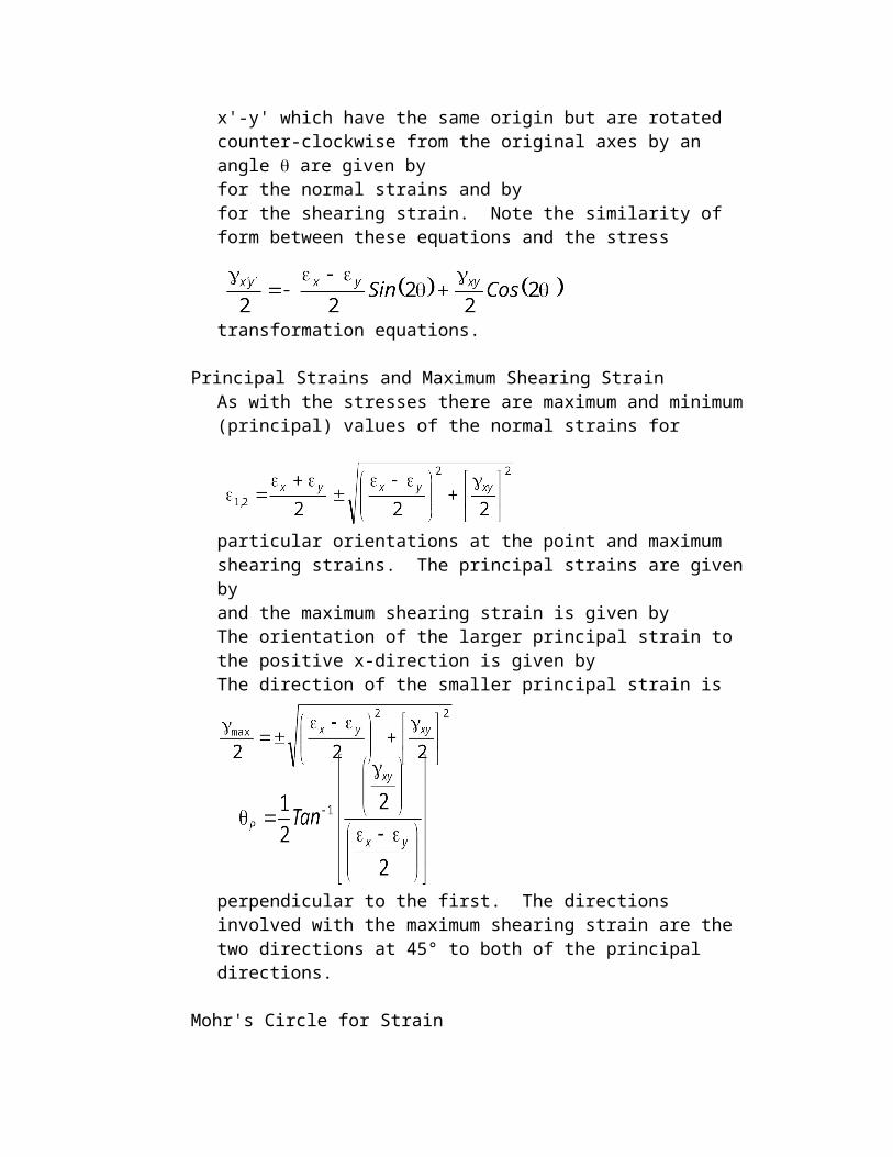
The relationship between the strains at a point measured relative to a set of axes x-y and a set x'-y' which have the same origin but are rotated counter-clockwise from the original axes by an angle are given by
for the normal strains and by
for the shearing strain. Note the similarity of form between these equations and the stress transformation equations.
Principal Strains and Maximum Shearing StrainAs with the stresses there are maximum and minimum (principal) values of the normal strains for particular orientations at the point and maximum shearing strains. The principal strains are given by
and the maximum shearing strain is given by
The orientation of the larger principal strain to the positive x-direction is given byThe direction of the smaller principal strain is perpendicular to the first. The directions involved with the maximum shearing strain are the two directions at 45° to both of the principal directions.
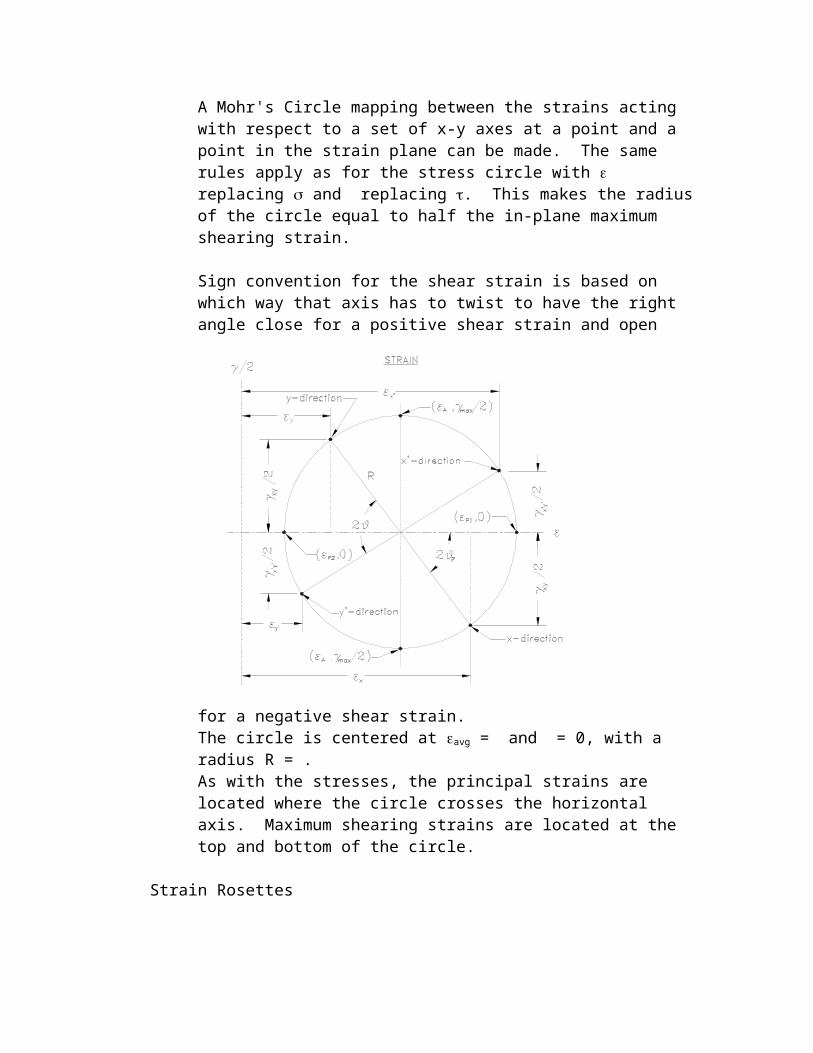
Mohr's Circle for StrainA Mohr's Circle mapping between the strains acting with respect to a set of x-y axes at a point and a point in the strain plane can be made. The same rules apply as for the stress circle with replacing and replacing . This makes the radius of the circle equal to half the in-plane maximum shearing strain.
Sign convention for the shear strain is based on which way that axis has to twist to have the right angle close for a positive shear strain and open for a negative shear strain.
The circle is centered at avg = and = 0, with a radius R = .As with the stresses, the principal strains are located where the circle crosses the horizontal axis. Maximum shearing strains are located at the top and bottom of the circle.
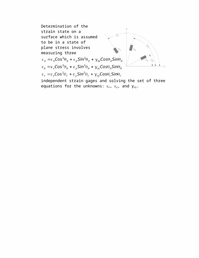
Strain Rosettes
Determination of the strain state on a surface which is assumed to be in a state of plane stress involves measuring three independent strain gages and solving the set of three equations for the unknowns: x, y, and γxy.
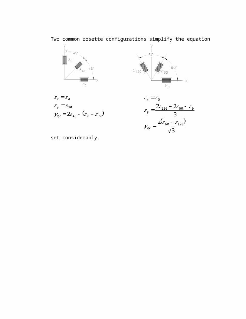
Two common rosette configurations simplify the equation set considerably.
Section 8: Material Properties
a. Poisson's Ratio
When a material is stretched in one direction it contracts in the lateral directions. The resulting longitudinal and lateral strains occur in a fixed ratio known as Poisson's ratio. The value of Poisson's ratio for a given material may be determined from a simple tension test as = - . The minus sign recognizes that the two strains always have opposite signs. This simple definition can be used to calculate the value of Poisson’s ratio only for a uniaxial stress state with the material still in the linear region where = E. In multidimensional stress states both strains are effected by stress induced strains in the other direction.
b. Generalized Hooke's Law
Three dimensional stress state.
These relationships are valid within the linear region of the materials stress-strain response.
G is the modulus of rigidity (shearing modulus of elasticity) G, E, and are related by the formula: G =
Plane stress state: z = xz = yz = 0
REVIEW PROBLEMS
1. An aluminum bar having a constant cross sectional area of 0.25 in2 carries the axial loads applied at the positions shown. Find the deformation of the bar.
a. ____ 0.0192 in.
b. ____ 0.2880 in.
c. ____ 0.3264 in.
d. ____ 0.3840 in.
e. ____ None of these.
2. A steel rod with a cross sectional area of 0.5 in2 is stretched between two rigid walls. The temperature coefficient of strain is 6.510-6 in./in./° and E is 30106 psi. If the tensile load is 2000 lb. at 80°F, find the tensile load at 0°F.
a. ____ 5800 lb.
b. ____ 7800 lb.
c. ____ 8800 lb.
d. ____ 9800 lb.
e. ____ 19,600 lb.
3. The composite bar shown is firmly attached to unyielding supports at the ends and is subjected to the axial load P shown. If the aluminum is stressed to 10,000 psi, find the stress in the steel.
a. ____ 1000 psi
b. ____ 2000 psi
c. ____ 5000 psi
d. ____ 10,000 psi
e. ____ 20,000 psi
4. Find the length L necessary to make the total angle of twist between the ends of the shaft equal zero.
a. ____ 3 ft.
b. ____ 4 ft.
c. ____ 6 ft.
d. ____ 9 ft.
e. ____ 12 ft.
5. Determine the shearing stress at points A and B which are at the inside and outside surfaces of the hollow shaft. Assume elastic behavior.
6. A hollow aluminum shaft and a solid steel shaft are rigidly connected at each end. This compound shaft is then loaded as shown. Determine the maximum shearing stress in each material and the angle of twist of the free end. Assume elastic behavior.Galuminum = 4106 psiGsteel = 12106 psi
7. Determine the maximum bending moment in the beam.
a. ____ 3600 ft-lb.
b. ____ 5400 ft-lb.
c. ____ 7200 ft-lb.
d. ____ 8100 ft-lb.
e. ____ 4050 ft-lb.
8. Find the maximum transverse shearing force in the beam shown.
a. ____ 450 lb.
b. ____ 1800 lb.
c. ____ 2250 lb.
d. ____ 3600 lb.
e. ____ 4050 lb.
9. By means of strain gages, the flexural stresses are found to be –12,000 psi at A and +4000 psi at B. Assuming the elastic limit of the material has not been exceeded; find the flexural stress at the bottom of the beam.
a. ____ 6000 psi.
b. ____ 8000 psi.
c. ____ 9000 psi.
d. ____ 10,000 psi.
e. ____ 12,000 psi.
10. For the cast iron beam shown, the maximum permissible compressive stress is 12,000 psi and the maximum permissible tensile stress is 5000 psi. Find the maximum safe load P that can be applied to the beam as shown.
a. ____ 220 lb.
b. ____ 333 lb.
c. ____ 1250 lb.
d. ____ 3000 lb.
e. ____ 7500 lb.
11. A 12-inch, 35-lb I-beam 30 ft. long is supported at 5 ft. from each end and carries a uniform distributed load of 1600 lbs per ft. (which includes its own weight). Determine the maximum flexural stress in the beam.
12. Find the maximum vertical shearing force which may be applied to a box beam having the cross section shown without exceeding a horizontal shearing stress of 500psi.
a. ____ 3065 lb.
b. ____ 4000 lb.
c. ____ 6000 lb.
d. ____ 6130 lb.
e. ____ 6300 lb.
13. Find the reaction at the right end of the beam shown.
a. ____ wL/8
b. ____ wL/4
c. ____ 3wL/8
14. Two beams, simply supported at their ends, jointly support a load P = 3500 lb. applied to the upper 6-ft. beam at its midpoint. The beams are identical except for length and cross at their midpoints. find the load carried by the lower 9-ft. beam.
a. ____ 700 lb.
b. ____ 800 lb.
c. ____ 1000 lb.
d. ____ 1750 lb.
e. ____ 2700 lb.
15. Determine the deflection at the end of this beam.
16. The critical Euler load for the pin-ended slender column restrained at the midpoint as shown in Fig. A is 1000 lb. What is the critical Euler load for the same column with the midpoint restraint removed as shown in Fig. B.
a. ____ 250 lb.
b. ____ 500 lb.
c. ____ 750 lb.
d. ____ 1000 lb.
e. ____ 4000 lb.
17. A rectangular bar is loaded as shown. Find the maximum tensile stress developed over section A-A.
18. For stress conditions on the element shown, find the principal stresses and the plane on which the maximum principal stress acts.
19. A circular shaft of brittle material subjected to torsion fractures along a 45° angle. Failure is due to what kind of stress?
a. ____ Shearing stress.
b. ____ Compressive stress.
c. ____ Tensile stress.
d. ____ Combined stress.
e. ____ None of these.
20. Which has the higher shear stress for a given elastic torque?
a. a one-inch diameter rod, or b. a two-inch diameter rod.
21. Identical rods of aluminum and steel are each subjected to the same elastic torque. Which rod will have the higher shear stress?
a. steel b. aluminum c. both have the same stress
22. If G represents the modulus of rigidity (or shear modulus of elasticity), E is the modulus of elasticity, and is Poisson’s ratio, which of the following statements is true for any homogeneous material?
a. ____ G is independent of E.
b. ____ G is 0.4E.
c. ____ G is 0.5E
d. ____ G depends upon both E and .
e. ____ None of these.
ANSWERS EIT REVIEWMECHANICS OF MATERIALS
1. c
2. d
3. e
4. d
5. B = 5,333.3 psi A = 2,666 psi
6. S = 81,528 psiA = 54,352 psi = 1.086 rad
7. e
8. c
9. b
10. d
11. max = 19,100 psi
12. d
13. c
14. b
15. 19.8 in.
16. a
17. 8,000 psi
18. max = 605 psi nmin = -6606 psi
19. c
20. a
21. c
22. d