
Product Information Manual, Air Impact Wrench, 2135TiMAX ...

M E C H A N I C A L R E B A R c o n n e c t i o n s s y s t e m s
p r e c a s t c o n c r e t e s o l u t i o n s
f i x i n g l i f t i n g c o n n e c t i n g
0 5

CLPT: combining deep exper ience with professional isat ion
CLPT was founded in 1995 and has more than 20 years o f exper ience in serv ing p recas t concre te cus tomers . New owners and a new management team came in to p lace in 2013 prov id ing a new dr ive to the company. Focus ing on fu r ther p ro fess iona l i sa t ion w i l l l ead to enhanced serv ice to our cus tomers and con t inued growth in Europe.CLPT prov ides a w ide and comple te range o f essent ia l p roduc ts to the p recas t - and bu i ld ing indus t ry to suppor t l i f t i ng , f i x ing and connec t ing . CLPT s tands fo r the h ighes t qua l i t y and sa fe ty a t a good and fa i r p r i ce . Cus tomer de l igh t i s our pass ion .
3w w w . c l p t . b e
0 5
Contents
ALPHA - SYSTEM, Advantage and Ins ta l la t ionPos i t ion Rebar Coup le r User ins t ruc t ion PRC pos i t ion coup le rMa le Connec t ion Coup le r Female Connec t ion Coup le r Cr imp ing Mach ine SCREWLOK Coup le r User ins t ruc t ion SLC pos i t ion coup le r
C.L .P.T. Produc t Range
4 - 55 - 66 - 7
89
10 - 1111 - 12
13 - 14
16
PRC
MCCFCC
PC-1100-SSLC
4
M E C H A N I C A L R E B A R c o n n e c t i o n s s y s t e m s
The Mechanical Rebar Connect ion ᾳ ALPHA - SYSTEM
Advantage of the ᾳ ALPHA - SYSTEM
The ALPHA-SYSTEM is a op t ima l , e f f i c ien t and most e f fec t i ve method o f connec t ing re in fo rcement s tee l , wh ich overcomes the d isadvantages o f the t rad i t iona l methods as over lap- and we ld ing o f the re in fo rcement s tee l .
The concept o f the female coup le r and the ma le th readed rebar coup le r a l low a connec t ion o f the re in fo rcement s tee l , where the charac te r i s t i cs a re equa l to tha t o f an un in te r rup ted re in fo rcement rebar because the fu l l ten -s i le s t reng th can be t rans fe r red w i th var iab le loads . The s tandard met r i c th read a l low an easy assembly on the cons t ruc t ion s i te o r in the p recas t fac to ry by us ing s tand-ard too ls and accessor ies .
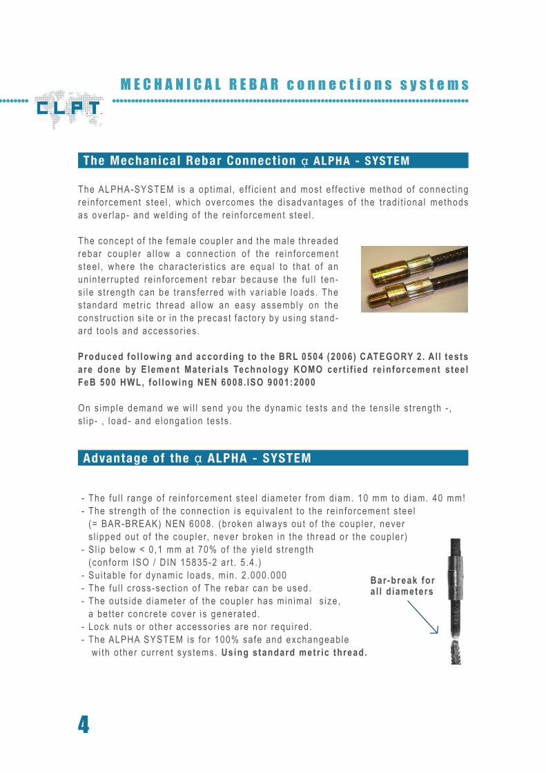
- The fu l l range o f re in fo rcement s tee l d iameter f rom d iam. 10 mm to d iam. 40 mm! - The s t reng th o f the connec t ion i s equ iva len t to the re in fo rcement s tee l (= BAR-BREAK) NEN 6008. (b roken a lways ou t o f the coup le r, never
s l ipped ou t o f the coup le r, never b roken in the th read or the coup le r ) - S l ip be low < 0 ,1 mm a t 70% o f the y ie ld s t reng th (con fo rm ISO / D IN 15835-2 a r t . 5 .4 . ) - Su i tab le fo r dynamic loads , m in . 2 .000 .000 - The fu l l c ross-sec t ion o f The rebar can be used. - The ou ts ide d iameter o f the coup le r has min ima l s ize ,
a be t te r concre te cover i s genera ted . - Lock nu ts o r o ther accessor ies a re nor requ i red . - The ALPHA SYSTEM is fo r 100% sa fe and exchangeab le w i th o ther cur ren t sys tems. Using standard metr ic thread.
Produced fo l lowing and according to the BRL 0504 (2006) CATEGORY 2 . A l l tests are done by Element Mater ia ls Technology KOMO cer t i f ied re inforcement s tee l FeB 500 HWL, fo l lowing NEN 6008. ISO 9001:2000
On s imp le demand we w i l l send you the dynamic tes ts and the tens i le s t reng th - , s l ip - , l oad- and e longat ion tes ts .
Bar-break for a l l d iameters
5w w w . c l p t . b e
0 5
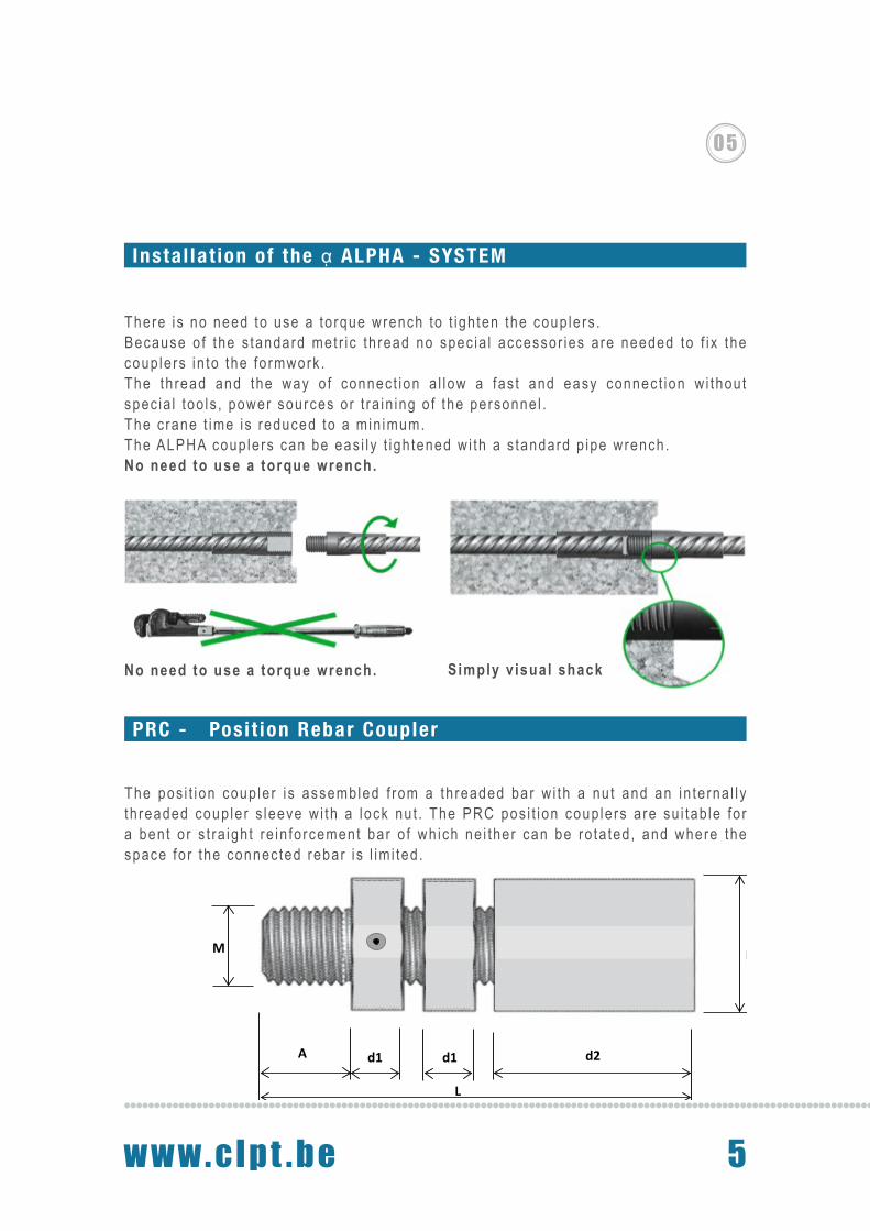
A d1 d1 d2
M D
L
Insta l lat ion of the ᾳ ALPHA - SYSTEM
There i s no need to use a to rque wrench to t igh ten the coup le rs .Because o f the s tandard met r i c th read no spec ia l accessor ies a re needed to f i x the coup le rs in to the fo rmwork .The th read and the way o f connec t ion a l low a fas t and easy connec t ion w i thou t spec ia l too ls , power sources o r t ra in ing o f the personne l .The c rane t ime is reduced to a min imum.The ALPHA coup le rs can be eas i l y t igh tened w i th a s tandard p ipe wrench.No need to use a torque wrench.
PRC - Posi t ion Rebar Coupler
The pos i t ion coup le r i s assembled f rom a th readed bar w i th a nu t and an in te rna l l y th readed coup le r s leeve w i th a lock nu t . The PRC pos i t ion coup le rs a re su i tab le fo r a ben t o r s t ra igh t re in fo rcement bar o f wh ich ne i ther can be ro ta ted , and where the space fo r the connec ted rebar i s l im i ted .
Simply v isual shackNo need to use a torque wrench.
6
M E C H A N I C A L R E B A R c o n n e c t i o n s s y s t e m s
User instruct ion PRC posi t ion coupler
Mater ia l : coup le r S tee l 52 .3 , z inc p la ted . The pos i t ion coup le r w i l l be de l i ve red assembled .
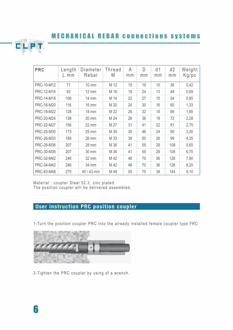
1 -Turn the pos i t ion coup le r PRC in to the a l ready ins ta l led female coup le r t ype FRC
2-Tigh ten the PRC coup le r by us ing o f a wrench .
PRC LengthL mm
DiameterRebar
Thread M
A mm
D mm
d1 mm
d2mm
Weigh tKg/pc
PRC-10-M12 71 10 mm M 12 15 19 10 36 0,42PRC-12-M16 93 12 mm M 16 19 24 13 48 0,69PRC-14-M18 106 14 mm M 14 22 27 15 54 0,85PRC-16-M20 116 16 mm M 20 24 30 16 60 1,33PRC-18-M22 128 18 mm M 22 26 32 18 66 1,85PRC-20-M24 138 20 mm M 24 28 36 19 72 2,28PRC-22-M27 156 22 mm M 27 31 41 22 81 2,75PRC-25-M30 173 25 mm M 30 35 46 24 90 3,30PRC-26-M33 189 26 mm M 33 38 50 26 99 4,35PRC-28-M36 207 28 mm M 36 41 55 29 108 5,65PRC-30-M36 207 30 mm M 36 41 55 29 108 6,70PRC-32-M42 246 32 mm M 42 48 70 36 126 7,90PRC-34-M42 246 34 mm M 42 48 70 36 126 8,20PRC-40-M48 275 40 / 43 mm M 48 55 75 38 144 9,10
7w w w . c l p t . b e
0 5
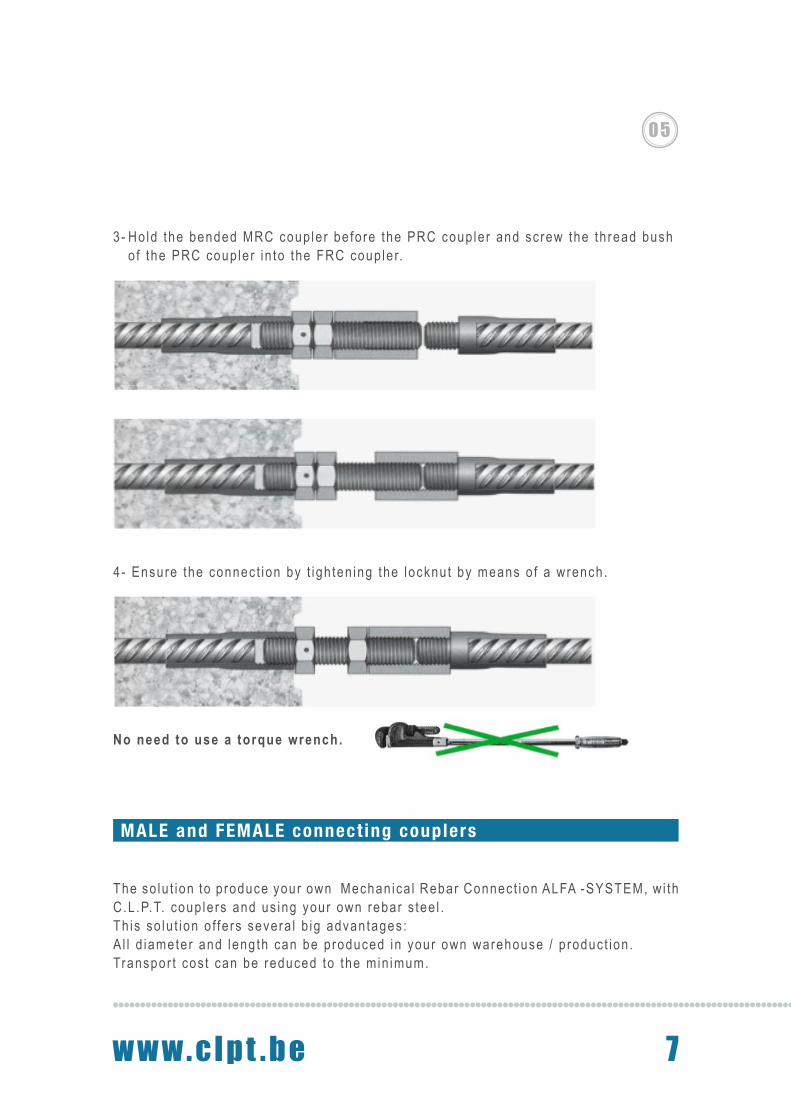
4- Ensure the connec t ion by t igh ten ing the locknut by means o f a wrench .
3- Ho ld the bended MRC coup le r be fo re the PRC coup le r and sc rew the th read bush o f the PRC coup le r in to the FRC coup le r.
PRC LengthL mm
DiameterRebar
Thread M
A mm
D mm
d1 mm
d2mm
Weigh tKg/pc
PRC-10-M12 71 10 mm M 12 15 19 10 36 0,42PRC-12-M16 93 12 mm M 16 19 24 13 48 0,69PRC-14-M18 106 14 mm M 14 22 27 15 54 0,85PRC-16-M20 116 16 mm M 20 24 30 16 60 1,33PRC-18-M22 128 18 mm M 22 26 32 18 66 1,85PRC-20-M24 138 20 mm M 24 28 36 19 72 2,28PRC-22-M27 156 22 mm M 27 31 41 22 81 2,75PRC-25-M30 173 25 mm M 30 35 46 24 90 3,30PRC-26-M33 189 26 mm M 33 38 50 26 99 4,35PRC-28-M36 207 28 mm M 36 41 55 29 108 5,65PRC-30-M36 207 30 mm M 36 41 55 29 108 6,70PRC-32-M42 246 32 mm M 42 48 70 36 126 7,90PRC-34-M42 246 34 mm M 42 48 70 36 126 8,20PRC-40-M48 275 40 / 43 mm M 48 55 75 38 144 9,10
MALE and FEMALE connect ing couplers
The so lu t ion to p roduce your own Mechan ica l Rebar Connec t ion ALFA -SYSTEM, w i th C.L .P.T. coup le rs and us ing your own rebar s tee l .Th is so lu t ion o f fe rs severa l b ig advantages :A l l d iameter and leng th can be p roduced in your own warehouse / p roduc t ion .Transpor t cos t can be reduced to the min imum.
No need to use a torque wrench.
8
M E C H A N I C A L R E B A R c o n n e c t i o n s s y s t e m s
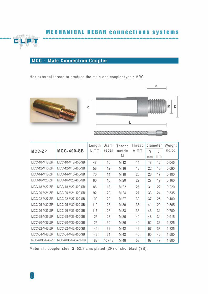
Has ex te rna l th read to p roduce the ma le end coup le r t ype : MRC
Mater ia l : coup le r s tee l S t 52 .3 z inc p la ted (ZP) o r sho t b las t (SB) .
MCC-ZP MCC-400-SBLengthL mm
Diam.rebar
Thread met r i c
M
Thread e mm
diameter Weigh tKg/pcD
mmd
mmMCC-10-M12-ZP MCC-10-M12-400-SB 47 10 M 12 14 18 12 0,045MCC-12-M16-ZP MCC-12-M16-400-SB 58 12 M 16 18 22 15 0,090MCC-14-M18-ZP MCC-14-M18-400-SB 70 14 M 18 20 26 17 0,100MCC-16-M20-ZP MCC-16-M20-400-SB 80 16 M 20 22 27 19 0,160MCC-18-M22-ZP MCC-18-M22-400-SB 86 18 M 22 25 31 22 0,220MCC-20-M24-ZP MCC-20-M24-400-SB 92 20 M 24 27 33 24 0,335MCC-22-M27-ZP MCC-22-M27-400-SB 100 22 M 27 30 37 26 0,400MCC-25-M30-ZP MCC-25-M30-400-SB 110 25 M 30 33 41 29 0,565MCC-26-M33-ZP MCC-26-M33-400-SB 117 26 M 33 36 46 31 0,700MCC-28-M36-ZP MCC-28-M36-400-SB 125 28 M 36 40 48 34 0,915MCC-30-M36-ZP MCC-30-M36-400-SB 125 30 M 36 40 52 36 1,225MCC-32-M42-ZP MCC-32-M42-400-SB 149 32 M 42 46 57 38 1,225MCC-34-M42-ZP MCC-34-M42-400-SB 149 34 M 42 46 60 40 1,500MCC-40/43-M48-ZP MCC-40/43-M48-400-SB 182 40 / 43 M 48 53 67 47 1,800
MCC - Male Connect ion Coupler
L
d M D
e
9w w w . c l p t . b e
0 5
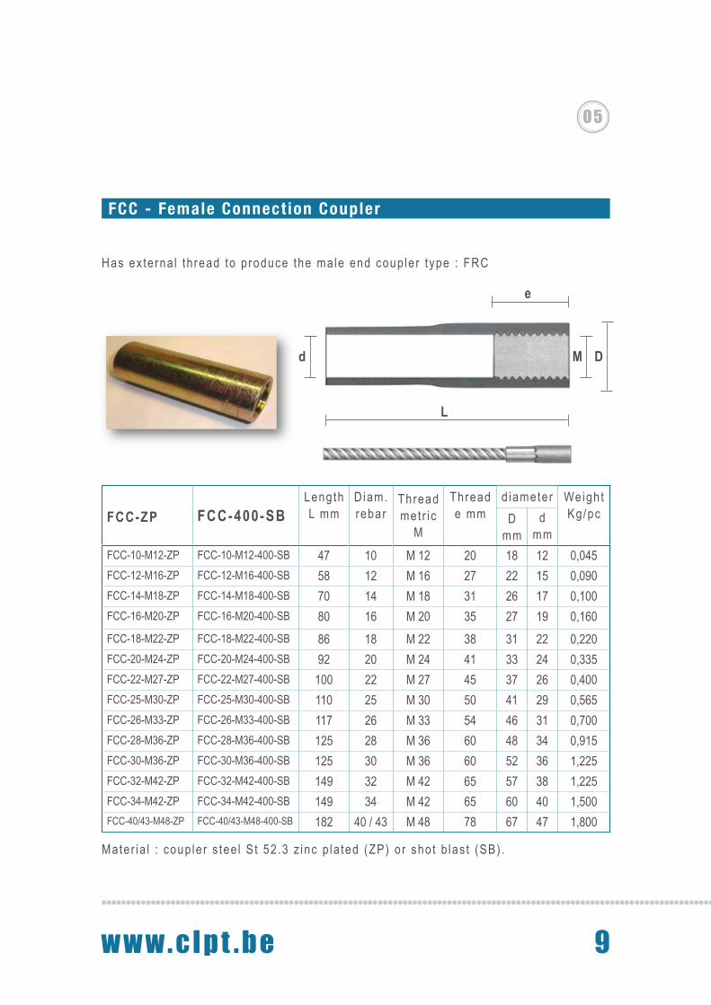
Has ex te rna l th read to p roduce the ma le end coup le r t ype : FRC
Mater ia l : coup le r s tee l S t 52 .3 z inc p la ted (ZP) o r sho t b las t (SB) .
MCC-ZP MCC-400-SBLengthL mm
Diam.rebar
Thread met r i c
M
Thread e mm
diameter Weigh tKg/pcD
mmd
mmMCC-10-M12-ZP MCC-10-M12-400-SB 47 10 M 12 14 18 12 0,045MCC-12-M16-ZP MCC-12-M16-400-SB 58 12 M 16 18 22 15 0,090MCC-14-M18-ZP MCC-14-M18-400-SB 70 14 M 18 20 26 17 0,100MCC-16-M20-ZP MCC-16-M20-400-SB 80 16 M 20 22 27 19 0,160MCC-18-M22-ZP MCC-18-M22-400-SB 86 18 M 22 25 31 22 0,220MCC-20-M24-ZP MCC-20-M24-400-SB 92 20 M 24 27 33 24 0,335MCC-22-M27-ZP MCC-22-M27-400-SB 100 22 M 27 30 37 26 0,400MCC-25-M30-ZP MCC-25-M30-400-SB 110 25 M 30 33 41 29 0,565MCC-26-M33-ZP MCC-26-M33-400-SB 117 26 M 33 36 46 31 0,700MCC-28-M36-ZP MCC-28-M36-400-SB 125 28 M 36 40 48 34 0,915MCC-30-M36-ZP MCC-30-M36-400-SB 125 30 M 36 40 52 36 1,225MCC-32-M42-ZP MCC-32-M42-400-SB 149 32 M 42 46 57 38 1,225MCC-34-M42-ZP MCC-34-M42-400-SB 149 34 M 42 46 60 40 1,500MCC-40/43-M48-ZP MCC-40/43-M48-400-SB 182 40 / 43 M 48 53 67 47 1,800
FCC-ZP FCC-400-SBLengthL mm
Diam.rebar
Thread met r i c
M
Thread e mm
diameter Weigh tKg/pcD
mmd
mmFCC-10-M12-ZP FCC-10-M12-400-SB 47 10 M 12 20 18 12 0,045FCC-12-M16-ZP FCC-12-M16-400-SB 58 12 M 16 27 22 15 0,090FCC-14-M18-ZP FCC-14-M18-400-SB 70 14 M 18 31 26 17 0,100FCC-16-M20-ZP FCC-16-M20-400-SB 80 16 M 20 35 27 19 0,160FCC-18-M22-ZP FCC-18-M22-400-SB 86 18 M 22 38 31 22 0,220FCC-20-M24-ZP FCC-20-M24-400-SB 92 20 M 24 41 33 24 0,335FCC-22-M27-ZP FCC-22-M27-400-SB 100 22 M 27 45 37 26 0,400FCC-25-M30-ZP FCC-25-M30-400-SB 110 25 M 30 50 41 29 0,565FCC-26-M33-ZP FCC-26-M33-400-SB 117 26 M 33 54 46 31 0,700FCC-28-M36-ZP FCC-28-M36-400-SB 125 28 M 36 60 48 34 0,915FCC-30-M36-ZP FCC-30-M36-400-SB 125 30 M 36 60 52 36 1,225FCC-32-M42-ZP FCC-32-M42-400-SB 149 32 M 42 65 57 38 1,225FCC-34-M42-ZP FCC-34-M42-400-SB 149 34 M 42 65 60 40 1,500FCC-40/43-M48-ZP FCC-40/43-M48-400-SB 182 40 / 43 M 48 78 67 47 1,800
FCC - Female Connect ion Coupler
L
d M D
e

10
M E C H A N I C A L R E B A R c o n n e c t i o n s s y s t e m s
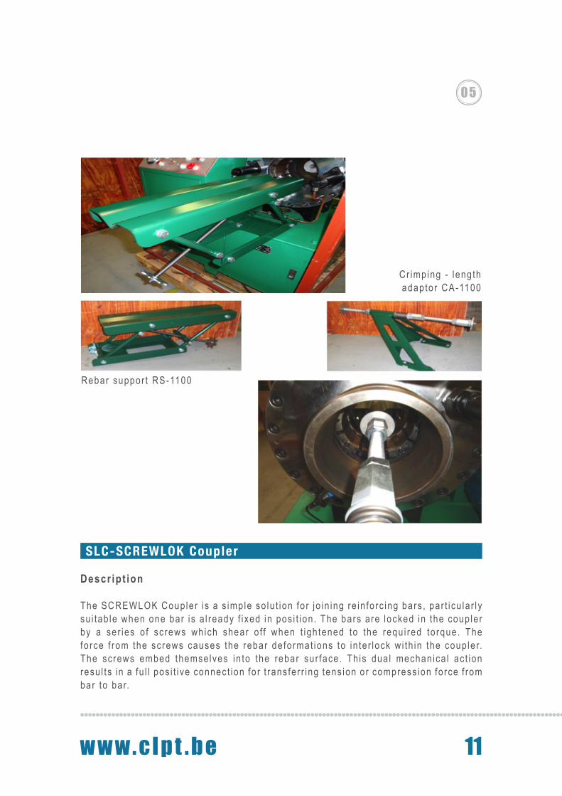
Crimping Machine Type : PC - 1100-S
The very s t rong 1098 ton p ress ing mach ine w i th 8 b locks (d ie se t ) i s su i tab le to connec t the A lpha sys tem coup le rs to re in fo rc ing s tee l . The press ing goes fas t and can be used fo r a l l l eng ths and d iameters o f re in fo rcement s tee l . The c r imp ing mach ine PC-1100-S can be used in most c i rcumstances , in p roduc t ion and on the jobs i te .
Cr imp ing fo rce : 1098 Ton / 10980 KnPower : 5 ,5 KwCur ren t in tens i ty : 3 -Ph. 380V, 50Hz
For Cr imping rebar d iameters : From diam. 10 mm (M 12) Ti l l d iam. 28 mm (M 36)
Oi l pump : p lunger pumpSystemat ic p ressure : 33 ,0 Mpa
The open ing and c r imp ing measurement o f the d ie : + / -19mmThe max open ing w i th : d iam. 108mmCr imp ing range up to 63 mm, ( inner d iameter o f the mach ine)Inc lud ing the 6 se ts o f d ies (1 d ie se t / coup le r d iameter ) .
O i l tank : 580 x 480 x 460 mm : 150LOi l t ype : hydrau l i c o i l < 10o C HM 32# : hydrau l i c o i l > 10o C HM 46#
Weigh t o f the mach ine (o i l no t inc luded) : 592 KgVo lume : 1300 x 730 x h :1200 mm
Add i t iona l d ies AD-1100
11w w w . c l p t . b e
0 5
SLC-SCREWLOK Coupler
Descr ipt ion
The SCREWLOK Coup le r i s a s imp le so lu t ion fo r jo in ing re in fo rc ing bars , par t i cu la r l y su i tab le when one bar i s a l ready f i xed in pos i t ion . The bars a re locked in the coup le r by a ser ies o f sc rews wh ich shear o f f when t igh tened to the requ i red to rque. The fo rce f rom the sc rews causes the rebar de fo rmat ions to in te r lock w i th in the coup le r. The sc rews embed themse lves in to the rebar sur face . Th is dua l mechan ica l ac t ion resu l ts in a fu l l pos i t i ve connec t ion fo r t rans fe r r ing tens ion o r compress ion fo rce f rom bar to bar.
Rebar suppor t RS-1100
Cr imp ing - leng thadaptor CA-1100
12
M E C H A N I C A L R E B A R c o n n e c t i o n s s y s t e m s
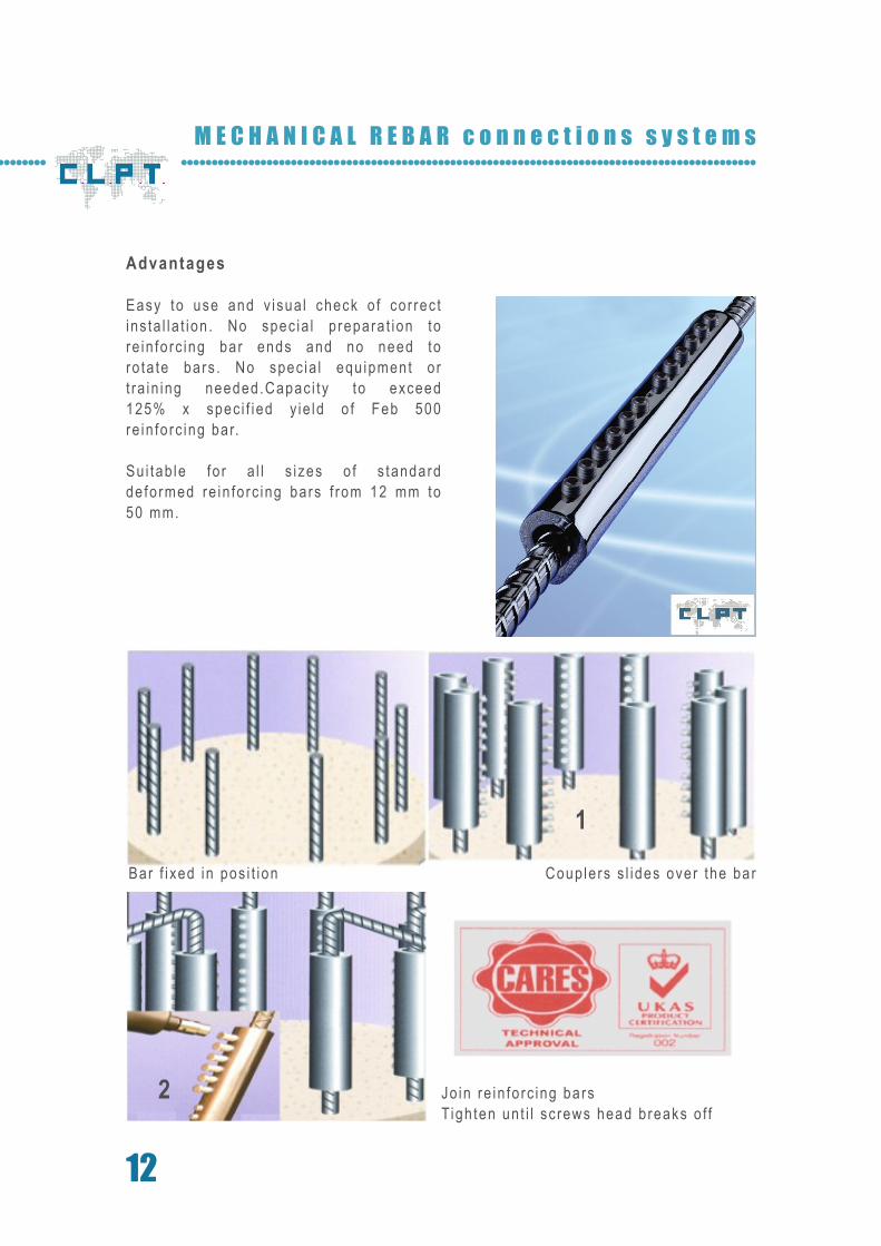
Bar f i xed in pos i t ion
Jo in re in fo rc ing barsTigh ten un t i l sc rews head breaks o f f
Coup le rs s l ides over the bar
Advantages
Easy to use and v isua l check o f cor rec t ins ta l la t ion . No spec ia l p repara t ion to re in fo rc ing bar ends and no need to ro ta te bars . No spec ia l equ ipment o r t ra in ing needed.Capac i ty to exceed 125% x spec i f ied y ie ld o f Feb 500 re in fo rc ing bar.
Su i tab le fo r a l l s i zes o f s tandard de fo rmed re in fo rc ing bars f rom 12 mm to 50 mm.
1
2
13w w w . c l p t . b e
0 5
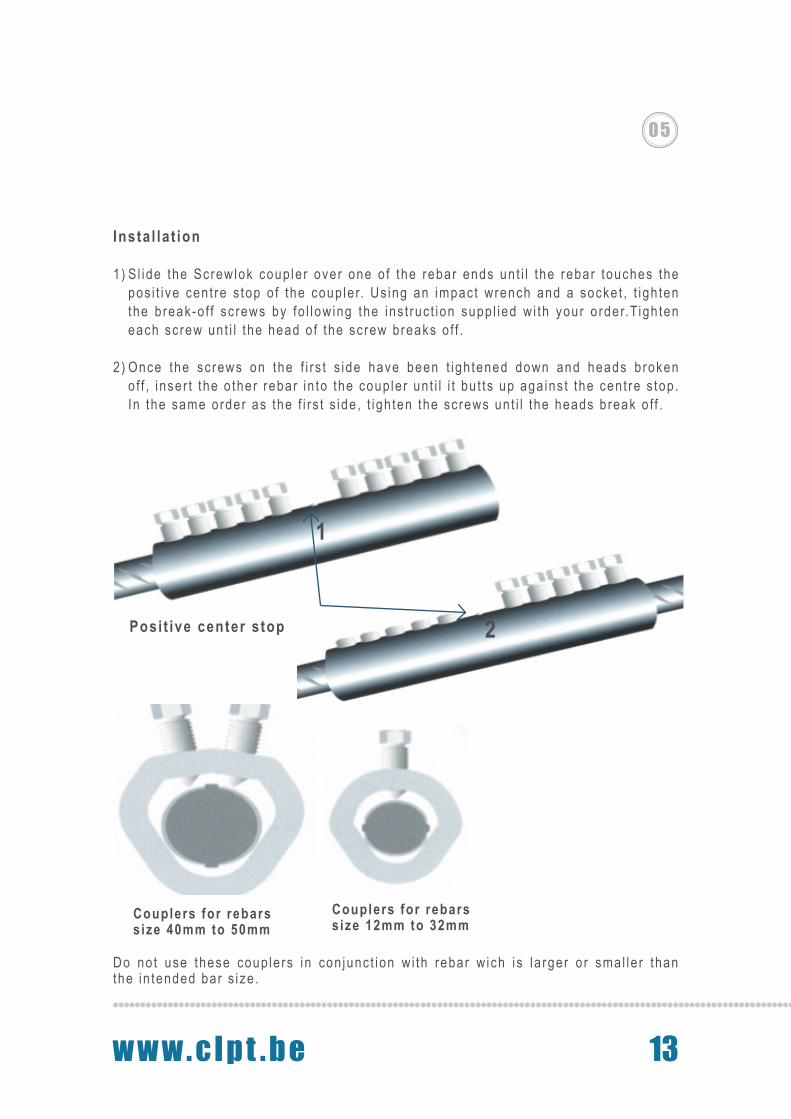
Insta l la t ion
1) S l ide the Screwlok coup le r over one o f the rebar ends un t i l the rebar touches the pos i t i ve cen t re s top o f the coup le r. Us ing an impac t wrench and a socke t , t igh ten the b reak-o f f sc rews by fo l low ing the ins t ruc t ion supp l ied w i th your o rder.Tigh ten each sc rew un t i l the head o f the sc rew breaks o f f .
2 ) Once the sc rews on the f i r s t s ide have been t igh tened down and heads b roken o f f , i nser t the o ther rebar in to the coup le r un t i l i t bu t ts up aga ins t the cen t re s top . In the same order as the f i r s t s ide , t igh ten the sc rews un t i l the heads b reak o f f .
1
posi t ive center s top
2Posi t ive center s top
Couplers for rebars s ize 40mm to 50mm
Couplers for rebars s ize 12mm to 32mm
Do no t use these coup le rs in con junc t ion w i th rebar w ich i s la rger o r sma l le r than the in tended bar s ize .
14
M E C H A N I C A L R E B A R c o n n e c t i o n s s y s t e m s
Fix ing Advise
For fas tes t ins ta l la t ion , use an a i r o r e lec t r i c d r i ven impac t wrench and su i tab le socke t . Make sure the impac t wrench is ra ted to ach ieve a t leas t the min imum impac t wrench to rque spec i f ied in char t hereunder to avo id s ta l l i ng .When manua l l y t igh ten ing the sc rews, use on ly a good qua l i t y wrench and hexagon socke t , wh ich can a t ta in the to rque spec i f ied .I f remova l o f the cen t re s top i s necessary, use a hammer and punch or la rge na i l to tap i t ou t o f the coup l ing body.Rep lace miss ing sc rews immedia te ly w i th Screwlok SLC spec ia l sc rews on ly. Do no t a l low th readed ho les to rus t .I f bars a re cor roded, remova l o f rus t / co r ros ion must be per fo rmed to the same degree as tha t requ i red to bond w i th concre te p r io r to Ins ta l l i ng the Screwlok SLC coup le r. Tes t ing o f o ld o r severe ly cor roded bars i s recommended to ensure the in teg t i t y o f the ad jo in ing bars and compl iance to des ign requ i rements .The Screwlok SLC coup le r i s no t su i tab le fo r use on curved rebars .
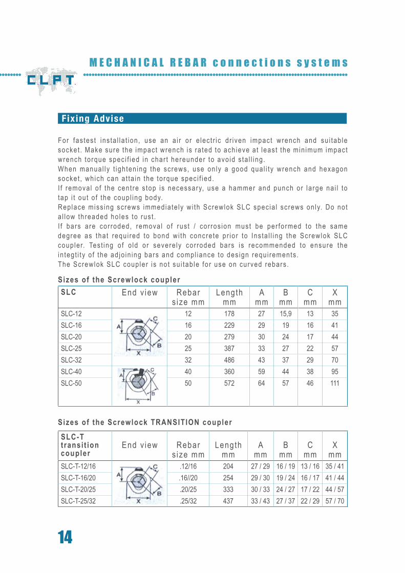
SLC End v iew Rebar s ize mm
Length mm
A mm
B mm
C mm
Xmm
SLC-12 12 178 27 15,9 13 35SLC-16 16 229 29 19 16 41SLC-20 20 279 30 24 17 44SLC-25 25 387 33 27 22 57SLC-32 32 486 43 37 29 70SLC-40 40 360 59 44 38 95SLC-50 50 572 64 57 46 111
SLC-Ttransi t ion coupler
End v iew Rebar s ize mm
Lengthmm
A mm
B mm
C mm
Xmm
SLC-T-12/16 .12/16 204 27 / 29 16 / 19 13 / 16 35 / 41SLC-T-16/20 .16//20 254 29 / 30 19 / 24 16 / 17 41 / 44SLC-T-20/25 .20/25 333 30 / 33 24 / 27 17 / 22 44 / 57SLC-T-25/32 .25/32 437 33 / 43 27 / 37 22 / 29 57 / 70
Sizes of the Screwlock coupler
Sizes of the Screwlock TRANSITION coupler

15w w w . c l p t . b e
0 5
SLC End v iew Rebar s ize mm
Length mm
A mm
B mm
C mm
Xmm
SLC-12 12 178 27 15,9 13 35SLC-16 16 229 29 19 16 41SLC-20 20 279 30 24 17 44SLC-25 25 387 33 27 22 57SLC-32 32 486 43 37 29 70SLC-40 40 360 59 44 38 95SLC-50 50 572 64 57 46 111
SLC-Ttransi t ion coupler
End v iew Rebar s ize mm
Lengthmm
A mm
B mm
C mm
Xmm
SLC-T-12/16 .12/16 204 27 / 29 16 / 19 13 / 16 35 / 41SLC-T-16/20 .16//20 254 29 / 30 19 / 24 16 / 17 41 / 44SLC-T-20/25 .20/25 333 30 / 33 24 / 27 17 / 22 44 / 57SLC-T-25/32 .25/32 437 33 / 43 27 / 37 22 / 29 57 / 70

C.L .P.T. bvbaAntwerpses teenweg 124 / 262630 Aar tse laar Be lg ium
te l . 0032 ( 0 ) 3 - 369 .11 .02fax . 0032 ( 0 ) 3 - 369 .11 .03e-mai l . i n fo@clp t .bewww.c lp t .be
1 D - TRANSPORT th readed L IFTING and F IX ING inser ts
2 D - TRANSPORT and L IFTING St r ip anchors .
3 D - TRANSPORT and L IFTING Spher ica l head anchors .
4 D - Cas t - in Anchor CHANNELS and Accessor ies .
Mechan ica l REBAR CONNECTION and Accessor ies
SANDWICH Anchor Sys tems.
Un iversa l MAGNETS and Accessor ies
JDA- Punch ing SHEAR REINFORCEMENT.
PRECAST spec ia l i t i es
All specif icat ions can be changed without prior notice.
0 9
0 8
0 7
0 6
0 5
0 4
0 3
0 2
0 1
PRODUCT RANGE