ME 304 CONTROL SYSTEMS - Middle East Technical...
55
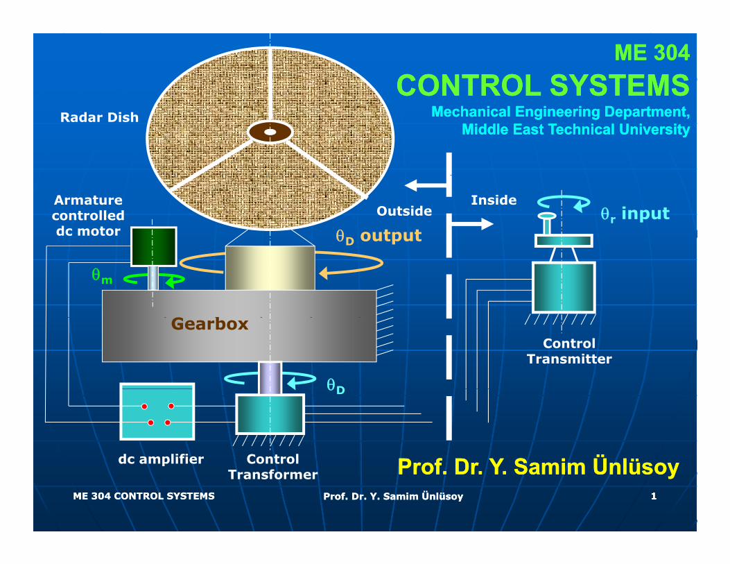
ME 304 ME 304 CONTROL SYSTEMS CONTROL SYSTEMS Mechanical Engineering Department, Mechanical Engineering Department, Middle East Technical University Middle East Technical University Radar Dish θ r input Armature controlled dc motor Outside Inside θ D output G b θ m Gearbox Control Transmitter θ D P fD YS i Ü lü P fD YS i Ü lü Control dc amplifier θ D ME 304 CONTROL SYSTEMS ME 304 CONTROL SYSTEMS Prof. Dr. Y. Samim Ünlüsoy Prof. Dr. Y. Samim Ünlüsoy 1 Prof. Dr. Y . Samim Ünlüsoy Prof. Dr. Y . Samim Ünlüsoy Control Transformer dc amplifier
Transcript of ME 304 CONTROL SYSTEMS - Middle East Technical...
ME 304ME 304CONTROL SYSTEMSCONTROL SYSTEMS
Mechanical Engineering Department,Mechanical Engineering Department,Middle East Technical UniversityMiddle East Technical University
Radar Dish
θr inputArmature controlleddc motor
OutsideInside
θD output
G b
θm
GearboxControl
Transmitter
θD
P f D Y S i Ü lüP f D Y S i Ü lüControl dc amplifier
θD
ME 304 CONTROL SYSTEMSME 304 CONTROL SYSTEMS Prof. Dr. Y. Samim ÜnlüsoyProf. Dr. Y. Samim Ünlüsoy 11
Prof. Dr. Y. Samim ÜnlüsoyProf. Dr. Y. Samim ÜnlüsoyControl Transformer
dc amplifier
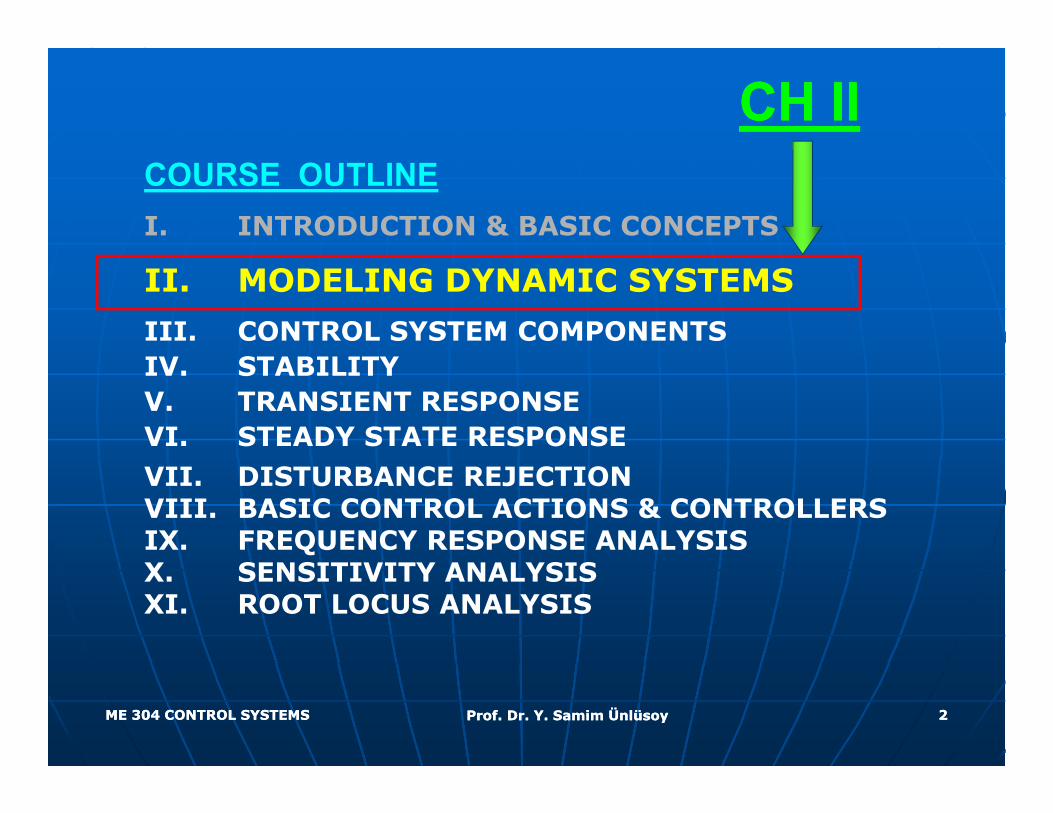
CH IICH IICOURSE OUTLINEI. INTRODUCTION & BASIC CONCEPTS
II. MODELING DYNAMIC SYSTEMS
III. CONTROL SYSTEM COMPONENTS IV. STABILITYV. TRANSIENT RESPONSEVI. STEADY STATE RESPONSEVII. DISTURBANCE REJECTIONVIII. BASIC CONTROL ACTIONS & CONTROLLERSIX. FREQUENCY RESPONSE ANALYSISX. SENSITIVITY ANALYSISXI. ROOT LOCUS ANALYSIS
ME 304 CONTROL SYSTEMSME 304 CONTROL SYSTEMS Prof. Dr. Y. Samim ÜnlüsoyProf. Dr. Y. Samim Ünlüsoy 22
MODELING DYNAMIC SYSTEMS MODELING DYNAMIC SYSTEMS OBJECTIVESOBJECTIVESOBJECTIVESOBJECTIVES
Deriving inputDeriving input--output relations of output relations of e g pute g put output e at o s ooutput e at o s olinear time invariant (LTI) systems linear time invariant (LTI) systems (mechanical, fluid, thermal, and (mechanical, fluid, thermal, and electrical) using elemental and electrical) using elemental and structural equations.structural equations.
Obtaining transfer function Obtaining transfer function representation of LTI systems.representation of LTI systems.
Representing control systems with Representing control systems with block diagrams.block diagrams.
ME 304 CONTROL SYSTEMSME 304 CONTROL SYSTEMS Prof. Dr. Y. Samim ÜnlüsoyProf. Dr. Y. Samim Ünlüsoy 33
MODELING DYNAMIC SYSTEMSMODELING DYNAMIC SYSTEMS
A A mathematical modelmathematical model of a physical of a physical system is a description of its system is a description of its dynamic behaviour in terms of dynamic behaviour in terms of
th ti l tith ti l timathematical equations.mathematical equations.
Once a mathematical model of a Once a mathematical model of a physical system is available, it is physical system is available, it is possible to study its dynamic possible to study its dynamic properties in detailproperties in detailproperties in detail.properties in detail.
ME 304 CONTROL SYSTEMSME 304 CONTROL SYSTEMS Prof. Dr. Y. Samim ÜnlüsoyProf. Dr. Y. Samim Ünlüsoy 44
MODELING DYNAMIC SYSTEMSMODELING DYNAMIC SYSTEMS
In developing a mathematical In developing a mathematical model,model, a compromise a compromise between between simplicitysimplicity of the of the
d l d th d l d th f f model and the model and the accuracyaccuracy of of the results must be reached.the results must be reached.
Model should be as simple as Model should be as simple as possible while providing all possible while providing all the required characteristics the required characteristics the required characteristics the required characteristics of the system in hand. of the system in hand.
ME 304 CONTROL SYSTEMSME 304 CONTROL SYSTEMS Prof. Dr. Y. Samim ÜnlüsoyProf. Dr. Y. Samim Ünlüsoy 55
MODELING DYNAMIC SYSTEMSMODELING DYNAMIC SYSTEMS
Mathematical models may be Mathematical models may be yyclassified as :classified as :
•• LumpedLumped or distributed parameteror distributed parameter•• LumpedLumped or distributed parameter,or distributed parameter,
•• LinearLinear or nonlinear,or nonlinear,
•• Time invariantTime invariant or time varying,or time varying,
•• DeterministicDeterministic or stochastic andor stochastic and•• DeterministicDeterministic or stochastic, andor stochastic, and
•• Continuous timeContinuous time or discrete time.or discrete time.
ME 304 CONTROL SYSTEMSME 304 CONTROL SYSTEMS Prof. Dr. Y. Samim ÜnlüsoyProf. Dr. Y. Samim Ünlüsoy 66
MODELING DYNAMIC SYSTEMSMODELING DYNAMIC SYSTEMS
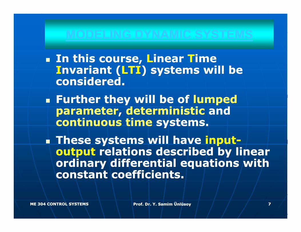
In this course, In this course, LLinear inear TTime ime IInvariant (nvariant (LTILTI) systems will be ) systems will be IInvariant (nvariant (LTILTI) systems will be ) systems will be considered. considered.
Further they will be of Further they will be of lumped lumped Further they will be of Further they will be of lumped lumped parameterparameter, , deterministic deterministic and and continuous timecontinuous time systems.systems.
These systems will have These systems will have inputinput--outputoutput relations described by linear relations described by linear
di diff ti l ti ith di diff ti l ti ith ordinary differential equations with ordinary differential equations with constant coefficients.constant coefficients.
ME 304 CONTROL SYSTEMSME 304 CONTROL SYSTEMS Prof. Dr. Y. Samim ÜnlüsoyProf. Dr. Y. Samim Ünlüsoy 77
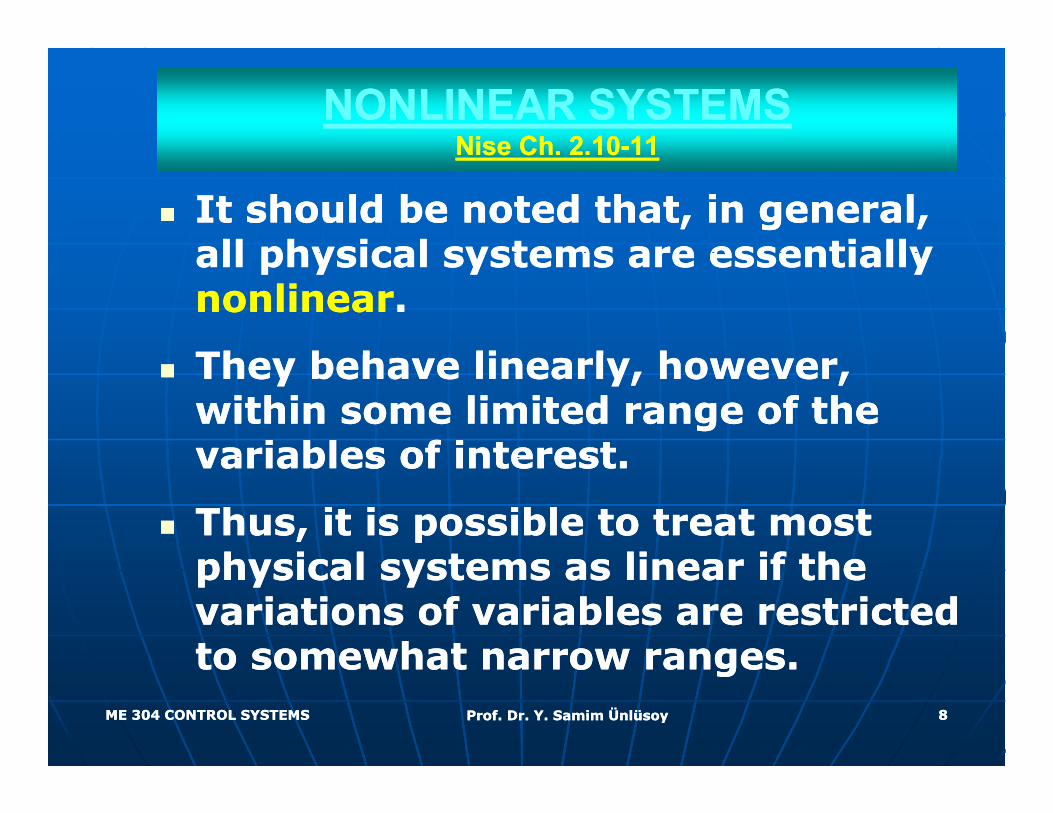
NONLINEAR SYSTEMSNONLINEAR SYSTEMSNise ChNise Ch 2 102 10--1111Nise Ch. Nise Ch. 2.102.10 1111
It should be noted that, in general, It should be noted that, in general, all physical systems are essentially all physical systems are essentially all physical systems are essentially all physical systems are essentially nonlinearnonlinear..
Th b h li l h Th b h li l h They behave linearly, however, They behave linearly, however, within some limited range of the within some limited range of the variables of interestvariables of interestvariables of interest.variables of interest.
Thus, it is possible to treat most Thus, it is possible to treat most physical systems as linear if the physical systems as linear if the physical systems as linear if the physical systems as linear if the variations of variables are restricted variations of variables are restricted to somewhat narrow ranges.to somewhat narrow ranges.
ME 304 CONTROL SYSTEMSME 304 CONTROL SYSTEMS Prof. Dr. Y. Samim ÜnlüsoyProf. Dr. Y. Samim Ünlüsoy 88
to somewhat narrow ranges.to somewhat narrow ranges.
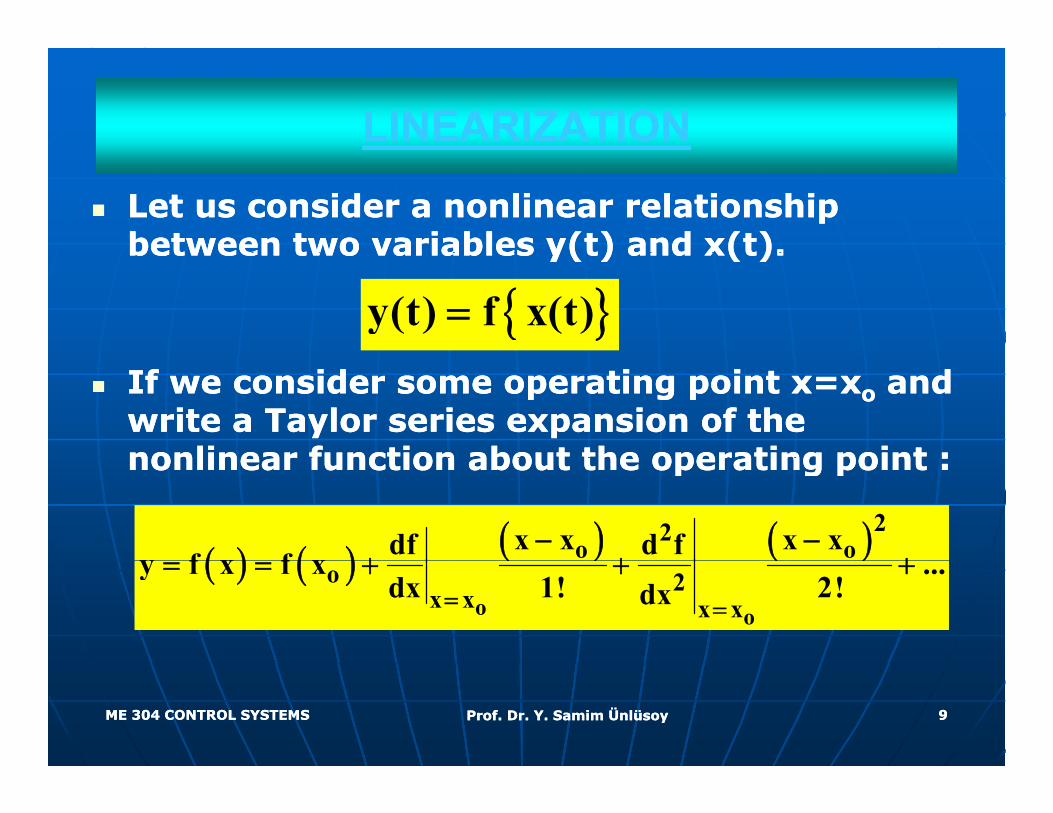
LINEARIZATIONLINEARIZATION
Let us consider a nonlinear relationship Let us consider a nonlinear relationship between two variables y(t) and x(t).between two variables y(t) and x(t).between two variables y(t) and x(t).between two variables y(t) and x(t).
{ }y(t) f x(t)=
If we consider some operating point x=xIf we consider some operating point x=xoo and and write a Taylor series expansion of the write a Taylor series expansion of the nonlinear function about the operating point :nonlinear function about the operating point :nonlinear function about the operating point :nonlinear function about the operating point :
( ) ( ) ( ) ( )22o ox x x xdf d fy f x f x
− −+ + +( ) ( ) ( ) ( )
o o
o 2x x x x
y f x f x ...dx 1! 2!dx= =
= = + + +
ME 304 CONTROL SYSTEMSME 304 CONTROL SYSTEMS Prof. Dr. Y. Samim ÜnlüsoyProf. Dr. Y. Samim Ünlüsoy 99
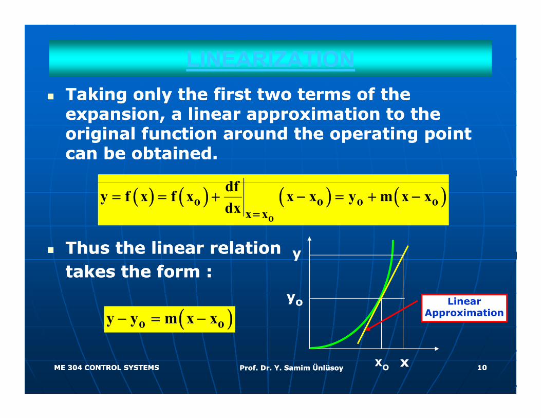
LINEARIZATIONLINEARIZATIONTaking only the first two terms of the Taking only the first two terms of the expansion, a linear approximation to the expansion, a linear approximation to the
i i l f ti d th ti i t i i l f ti d th ti i t original function around the operating point original function around the operating point can be obtained.can be obtained.
df( ) ( ) ( ) ( )o
o o o ox x
dfy f x f x x x y m x xdx =
= = + − = + −
Thus the linear relationThus the linear relationtakes the form :takes the form :
y
( )o oy y m x x− = −yo Linear
Approximation
ME 304 CONTROL SYSTEMSME 304 CONTROL SYSTEMS Prof. Dr. Y. Samim ÜnlüsoyProf. Dr. Y. Samim Ünlüsoy 1010xo x
LINEARIZATIONLINEARIZATION
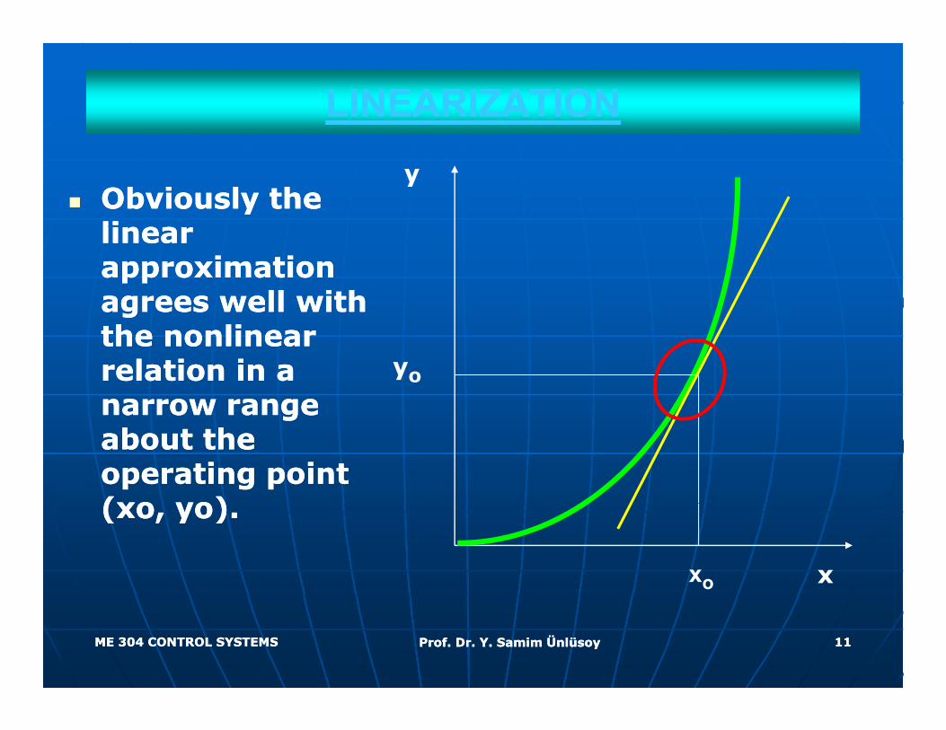
Obviously the Obviously the linea linea
y
linear linear approximation approximation agrees well with agrees well with the nonlinear the nonlinear relation in a relation in a narrow range narrow range
yo
narrow range narrow range about the about the operating point operating point (xo yo)(xo yo)(xo, yo).(xo, yo).
xo x
ME 304 CONTROL SYSTEMSME 304 CONTROL SYSTEMS Prof. Dr. Y. Samim ÜnlüsoyProf. Dr. Y. Samim Ünlüsoy 1111
LINEARIZATION LINEARIZATION -- ExampleExample
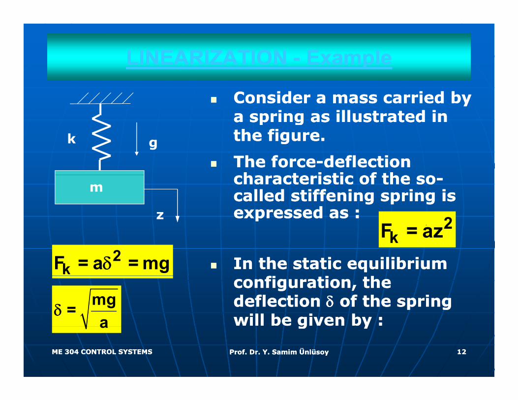
Consider a mass carried by Consider a mass carried by a spring as illustrated in a spring as illustrated in p gp gthe figure. the figure.
The forceThe force--deflection deflection h t i ti f th h t i ti f th
k g
characteristic of the socharacteristic of the so--called stiffening spring is called stiffening spring is expressed as :expressed as : 2F
m
z
In the static equilibrium In the static equilibrium
2kF = az
2kF = a = mgδ
configuration, the configuration, the deflection deflection δδ of the spring of the spring will be given by :will be given by :
mg=a
δ
ME 304 CONTROL SYSTEMSME 304 CONTROL SYSTEMS Prof. Dr. Y. Samim ÜnlüsoyProf. Dr. Y. Samim Ünlüsoy 1212
g yg ya
LINEARIZATION LINEARIZATION -- ExampleExample
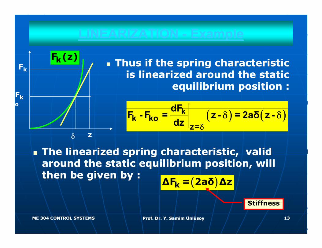
Thus if the spring characteristicThus if the spring characteristicis linearized around the static is linearized around the static
Fk
kF (z)
is linearized around the static is linearized around the static equilibrium position :equilibrium position :
kdFFko
( ) ( )kk ko
z=
dFF - F = z - = 2aδ z -
dz δδ δ
δ z
The linearized spring characteristic, valid The linearized spring characteristic, valid around the static equilibrium position, will around the static equilibrium position, will then be given by :then be given by : ( )kΔF = 2aδ Δz
Stiffness
ME 304 CONTROL SYSTEMSME 304 CONTROL SYSTEMS Prof. Dr. Y. Samim ÜnlüsoyProf. Dr. Y. Samim Ünlüsoy 1313
Stiffness
MODELING DYNAMIC SYSTEMSMODELING DYNAMIC SYSTEMS
In deriving inputIn deriving input--output relations for a output relations for a t th d d t il d b l t th d d t il d b l system, the procedure detailed below system, the procedure detailed below
may be followed.may be followed.
•• Define the Define the inputinput and and outputoutput..
•• Break the system into its elements.Break the system into its elements.
•• Write the Write the elementalelemental equations.equations.
•• Write the Write the structuralstructural equations.equations.
•• Combine elemental and structural Combine elemental and structural equations to relate input and output. equations to relate input and output.
ME 304 CONTROL SYSTEMSME 304 CONTROL SYSTEMS Prof. Dr. Y. Samim ÜnlüsoyProf. Dr. Y. Samim Ünlüsoy 1414
MODELING DYNAMIC SYSTEMSMODELING DYNAMIC SYSTEMS
ElementalElemental equations can be equations can be written for each element of a written for each element of a system irrespective of the way system irrespective of the way th t d t h th t d t h they are connected to each they are connected to each other.other.
StructuralStructural equations describe equations describe how these elements are how these elements are
t d t f th tt d t f th tconnected to form the system.connected to form the system.
ME 304 CONTROL SYSTEMSME 304 CONTROL SYSTEMS Prof. Dr. Y. Samim ÜnlüsoyProf. Dr. Y. Samim Ünlüsoy 1515
ELEMENTAL EQUATIONSELEMENTAL EQUATIONST l ti l M h i l El tT l ti l M h i l El tTranslational Mechanical ElementsTranslational Mechanical Elements
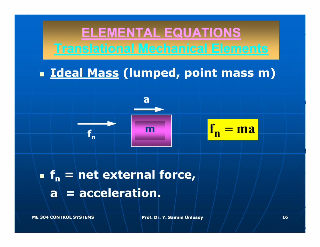
Ideal Ideal MassMass (lumped, point mass m)(lumped, point mass m)deadea assass ( u ped, po t ass )( u ped, po t ass )
a
m nf ma=fn
ff l fl fffnn = net external force, = net external force,
a = acceleration.a = acceleration.
ME 304 CONTROL SYSTEMSME 304 CONTROL SYSTEMS Prof. Dr. Y. Samim ÜnlüsoyProf. Dr. Y. Samim Ünlüsoy 1616
Translational Mechanical ElementsTranslational Mechanical Elements
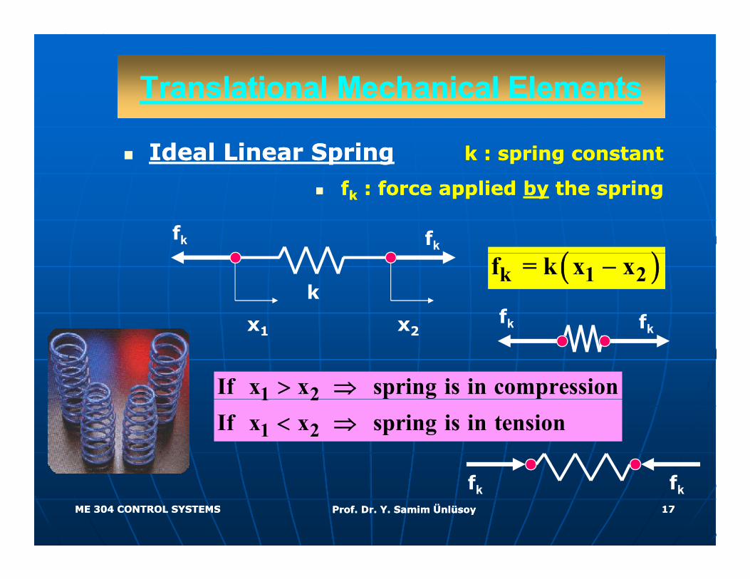
Ideal Linear SpringIdeal Linear Spring k : spring constantk : spring constant
ffkk : force applied : force applied byby the springthe spring
( )fk fk
( )k 1 2f = k x x−
x x2
kfk fk
1 2If x x spring is in compression> ⇒
x1 x2k fk
1 2
1 2If x x spring is in tension< ⇒
ME 304 CONTROL SYSTEMSME 304 CONTROL SYSTEMS Prof. Dr. Y. Samim ÜnlüsoyProf. Dr. Y. Samim Ünlüsoy 1717
fk fk

Translational Mechanical ElementsTranslational Mechanical Elements
Ideal Linear SpringIdeal Linear Spring k : spring constantk : spring constant
ffkk : force applied : force applied byby the springthe spring
Ideal spring with one end fixed:Ideal spring with one end fixed:
kf = kxfk
k
x
k
ME 304 CONTROL SYSTEMSME 304 CONTROL SYSTEMS Prof. Dr. Y. Samim ÜnlüsoyProf. Dr. Y. Samim Ünlüsoy 1818
Translational Mechanical ElementsTranslational Mechanical Elements
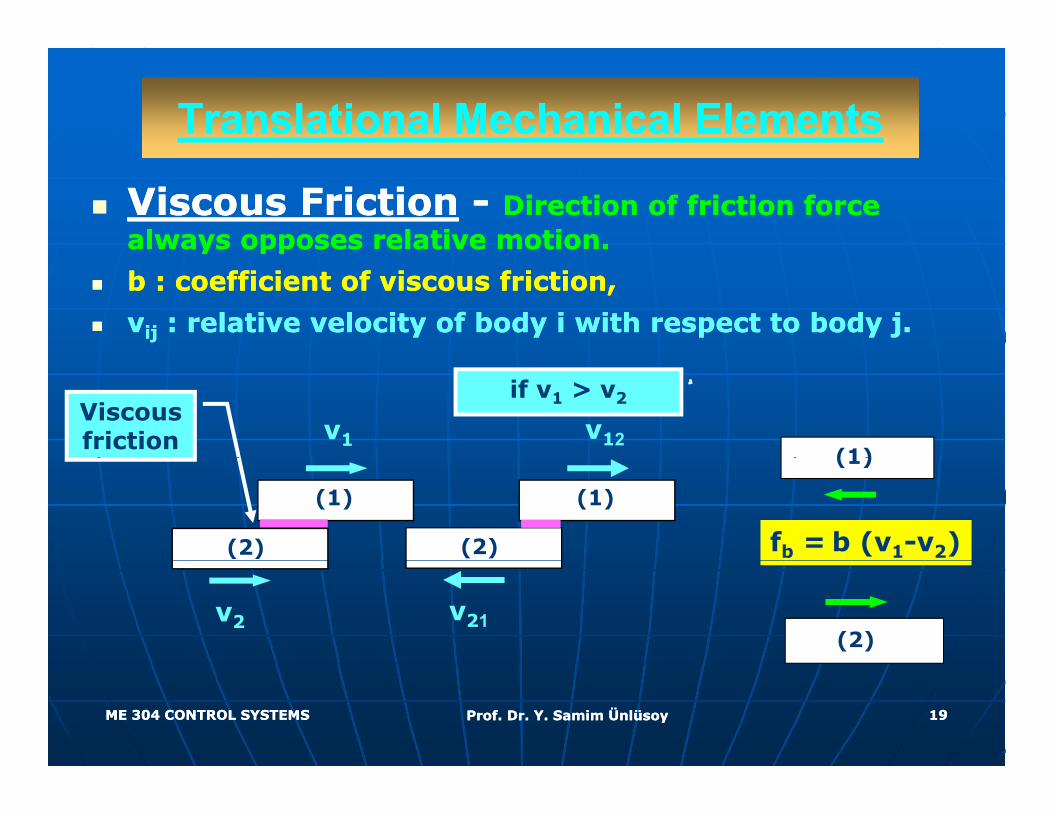
Viscous FrictionViscous Friction -- Direction of friction force Direction of friction force always opposes relative motion.always opposes relative motion.y ppy pp
b : coefficient of viscous friction, b : coefficient of viscous friction,
vvijij : relative velocity of body i with respect to body j.: relative velocity of body i with respect to body j.
(1)v1
Viscous friction
if v1 > v2
v12
fb = b (v1-v2)
(1)
(1)
(2)
(1)
(2)
(2)v2 v21
ME 304 CONTROL SYSTEMSME 304 CONTROL SYSTEMS Prof. Dr. Y. Samim ÜnlüsoyProf. Dr. Y. Samim Ünlüsoy 1919
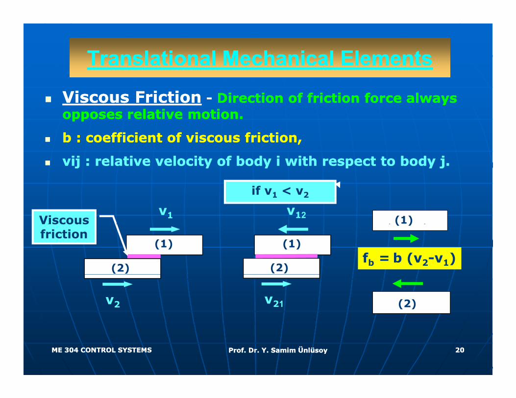
Translational Mechanical ElementsTranslational Mechanical Elements
Viscous FrictionViscous Friction -- Direction of friction force always Direction of friction force always opposes relative motion.opposes relative motion.
b : coefficient of viscous friction,b : coefficient of viscous friction,
vij : relative velocity of body i with respect to body j.vij : relative velocity of body i with respect to body j.
v1Viscous (1)
if v1 < v2
v12
(1)
(2)
scousfriction
fb = b (v2-v1)
( )
(1)
(2)
v2 (2)v21
ME 304 CONTROL SYSTEMSME 304 CONTROL SYSTEMS Prof. Dr. Y. Samim ÜnlüsoyProf. Dr. Y. Samim Ünlüsoy 2020
Translational Mechanical ElementsTranslational Mechanical Elements
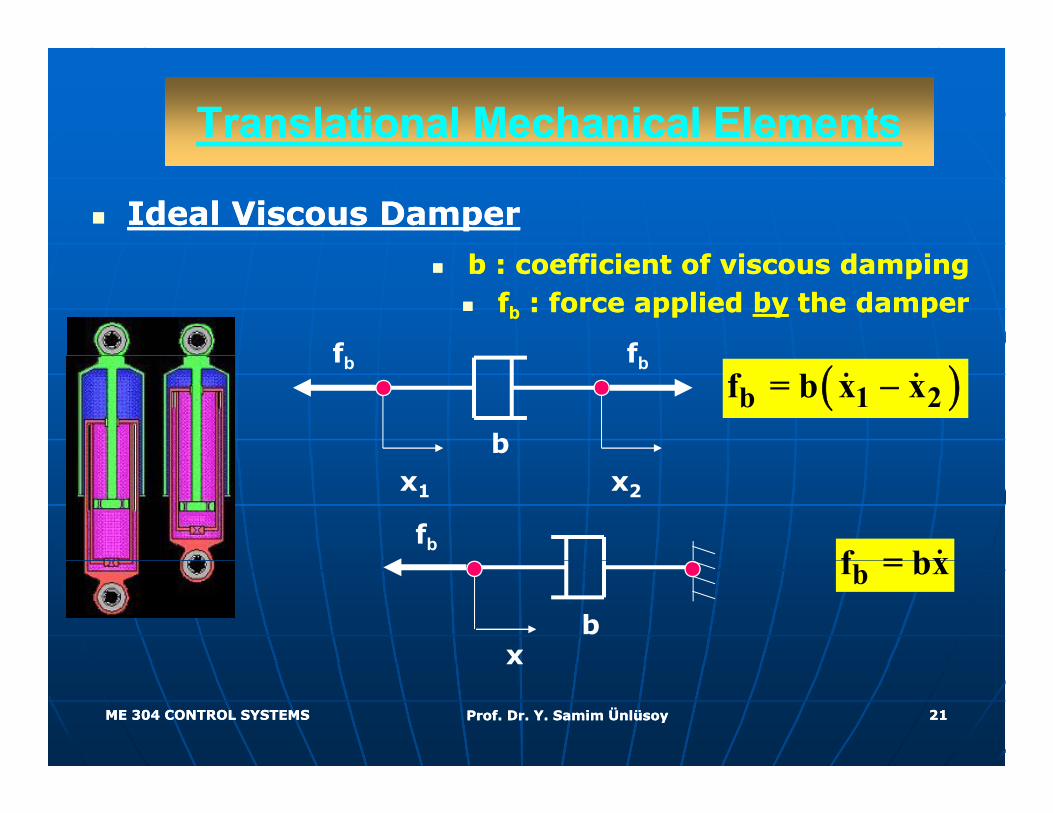
Ideal Viscous DamperIdeal Viscous Damper
b : coefficient of viscous dampingb : coefficient of viscous dampingffbb : force applied : force applied byby the damperthe damper
ff( )b 1 2f = b x x−
fbfb
b
f = bxfb
x1 x2
bf = bx
xb
ME 304 CONTROL SYSTEMSME 304 CONTROL SYSTEMS Prof. Dr. Y. Samim ÜnlüsoyProf. Dr. Y. Samim Ünlüsoy 2121
x
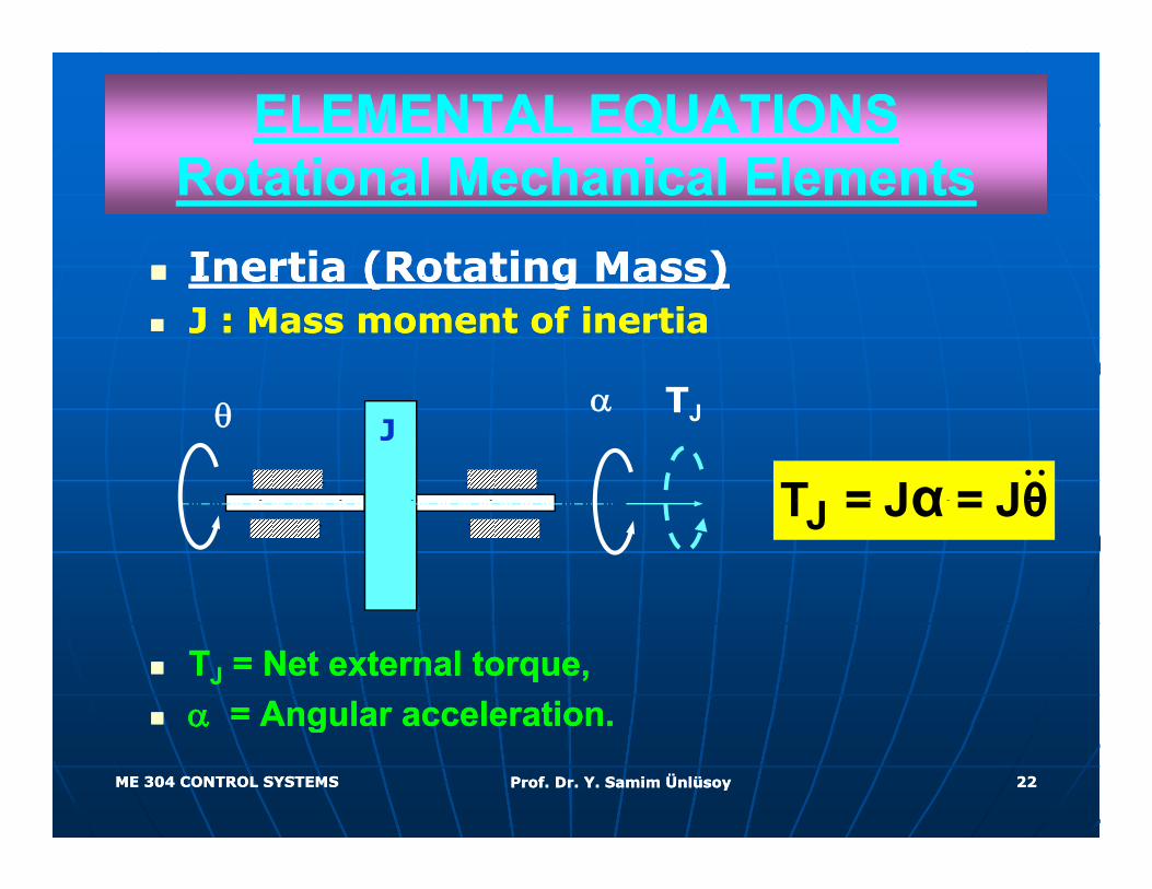
ELEMENTAL EQUATIONSELEMENTAL EQUATIONSR t ti l M h i l El tR t ti l M h i l El tRotational Mechanical ElementsRotational Mechanical ElementsInertia (Rotating Mass)Inertia (Rotating Mass)Inertia (Rotating Mass)Inertia (Rotating Mass)J : Mass moment of inertiaJ : Mass moment of inertia
TJ
α TJ
T = J = Jθαθ
JT = J = Jθα
TTJJ = Net external torque,= Net external torque,αα = Angular acceleration.= Angular acceleration.
ME 304 CONTROL SYSTEMSME 304 CONTROL SYSTEMS Prof. Dr. Y. Samim ÜnlüsoyProf. Dr. Y. Samim Ünlüsoy 2222
αα Angular acceleration. Angular acceleration.
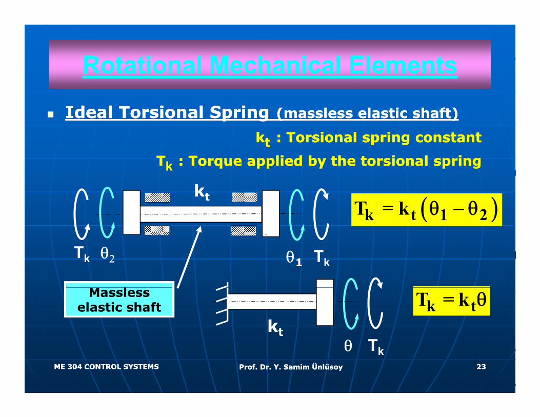
Rotational Mechanical ElementsRotational Mechanical Elements
Ideal Torsional SpringIdeal Torsional Spring (massless elastic shaft)(massless elastic shaft)
kktt : Torsional spring constant: Torsional spring constant
TTkk : Torque applied by the torsional spring: Torque applied by the torsional spring
( )k t 1 2T = k θ − θkt
θ1θ2
l
Tk Tk
Massless elastic shaft
Tθ
k tT = k θkt
ME 304 CONTROL SYSTEMSME 304 CONTROL SYSTEMS Prof. Dr. Y. Samim ÜnlüsoyProf. Dr. Y. Samim Ünlüsoy 2323
Tkθ
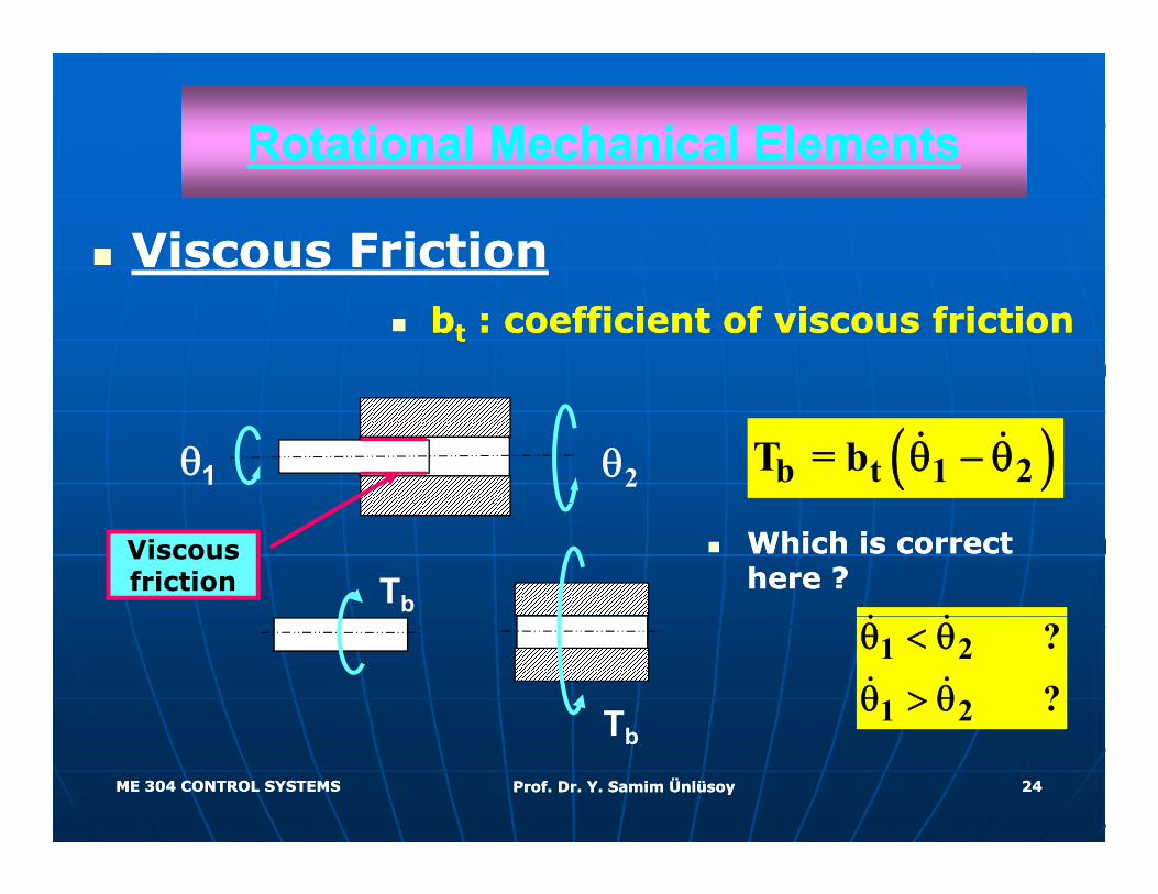
Rotational Mechanical ElementsRotational Mechanical Elements
Viscous FrictionViscous Frictionbbtt : coefficient of viscous friction: coefficient of viscous friction
( )b t 1 2T = b θ − θθ2θ1(2)
Viscous friction Tb
Which is correct Which is correct here ? here ?
(2)
Tb
1 2
1 2
?
?
θ < θ
θ > θ
ME 304 CONTROL SYSTEMSME 304 CONTROL SYSTEMS Prof. Dr. Y. Samim ÜnlüsoyProf. Dr. Y. Samim Ünlüsoy 2424
Tb
STRUCTURAL EQUATIONSSTRUCTURAL EQUATIONS
Structural equations describe how the Structural equations describe how the elements are connected to form the system elements are connected to form the system elements are connected to form the system. elements are connected to form the system.
There are two types of structural equations.There are two types of structural equations.
•• Continuity equationsContinuity equations In mechanical In mechanical •• Continuity equationsContinuity equations. In mechanical . In mechanical systems, these correspond to systems, these correspond to force (or force (or torque) balance torque) balance at a node or on an at a node or on an elementelementelementelement..
•• Compatibility equationsCompatibility equations. In mechanical . In mechanical systems, these correspond to kinematic systems, these correspond to kinematic systems, these correspond to kinematic systems, these correspond to kinematic position, velocity, and acceleration position, velocity, and acceleration relations. relations.
ME 304 CONTROL SYSTEMSME 304 CONTROL SYSTEMS Prof. Dr. Y. Samim ÜnlüsoyProf. Dr. Y. Samim Ünlüsoy 2525
STRUCTURAL EQUATIONSSTRUCTURAL EQUATIONS
After gaining some After gaining some g gg gexperience, oneexperience, one may may draw draw and annotate the free body and annotate the free body di h th t thdi h th t thdiagrams such that thediagrams such that thestructuralstructural equations are equations are automatically implemented automatically implemented automatically implemented automatically implemented and do not have to be written and do not have to be written separatelyseparatelyseparately.separately.
ME 304 CONTROL SYSTEMSME 304 CONTROL SYSTEMS Prof. Dr. Y. Samim ÜnlüsoyProf. Dr. Y. Samim Ünlüsoy 2626
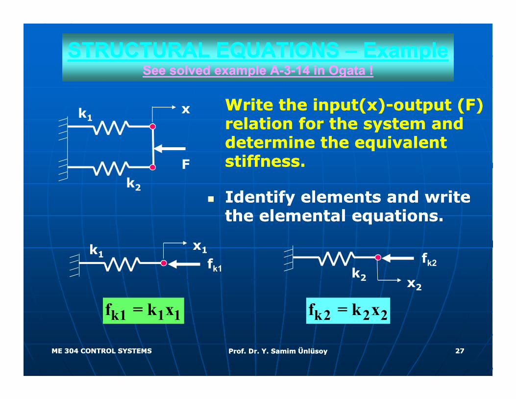
STRUCTURAL EQUATIONS STRUCTURAL EQUATIONS –– Example Example See solved example ASee solved example A--33--14 in Ogata !14 in Ogata !See solved example ASee solved example A 33 14 in Ogata !14 in Ogata !
Write the input(x)Write the input(x)--output (F) output (F) relation for the system and relation for the system and
k1x
relation for the system and relation for the system and determine the equivalent determine the equivalent stiffness.stiffness.F
Identify elements and write Identify elements and write the elemental equations.the elemental equations.
k2
fk2k2
k1x1
fk1
k1 1 1f = k x
k2 x2
k2 2 2f = k x
ME 304 CONTROL SYSTEMSME 304 CONTROL SYSTEMS Prof. Dr. Y. Samim ÜnlüsoyProf. Dr. Y. Samim Ünlüsoy 2727
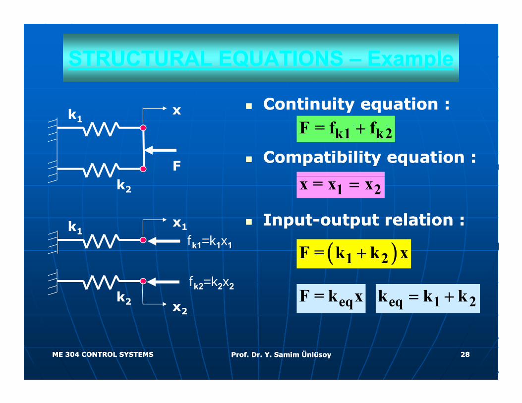
STRUCTURAL EQUATIONS STRUCTURAL EQUATIONS –– Example Example
Continuity equation :Continuity equation :k1
xF f f+
Compatibility equation :Compatibility equation :F
k1 k2F = f f+
InputInput--output relation :output relation :
k2
k x1
1 2x = x x=
pp ppk1 1
fk1=k1x1 ( )1 2F = k k x+
f keqF = k x eq 1 2k k k= +k2 x2
fk2=k2x2
ME 304 CONTROL SYSTEMSME 304 CONTROL SYSTEMS Prof. Dr. Y. Samim ÜnlüsoyProf. Dr. Y. Samim Ünlüsoy 2828
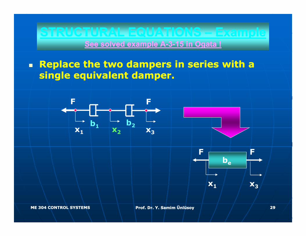
STRUCTURAL EQUATIONS STRUCTURAL EQUATIONS –– ExampleExampleSee solved example ASee solved example A 33 15 in Ogata !15 in Ogata !See solved example ASee solved example A--33--15 in Ogata !15 in Ogata !
Replace the two dampers in series with a Replace the two dampers in series with a single eq i alent dampesingle eq i alent dampesingle equivalent damper.single equivalent damper.
FF
x3
F
b2x1 x2
F
b131 2
F Fbe
x3x1
be
ME 304 CONTROL SYSTEMSME 304 CONTROL SYSTEMS Prof. Dr. Y. Samim ÜnlüsoyProf. Dr. Y. Samim Ünlüsoy 2929
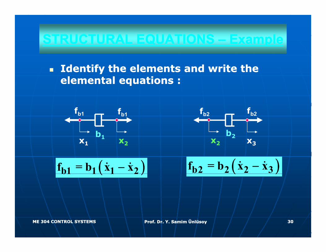
STRUCTURAL EQUATIONS STRUCTURAL EQUATIONS –– ExampleExample
Identify the elements and write the Identify the elements and write the elemental eq ations elemental eq ations elemental equations :elemental equations :
f ff f fb2
x3
fb2
b2x2x1 x2
fb1
b1
fb1
( )b1 1 1 2f = b x x−
x3x2x1 x2
( )b2 2 2 3f = b x x−( )b1 1 1 2 ( )
ME 304 CONTROL SYSTEMSME 304 CONTROL SYSTEMS Prof. Dr. Y. Samim ÜnlüsoyProf. Dr. Y. Samim Ünlüsoy 3030
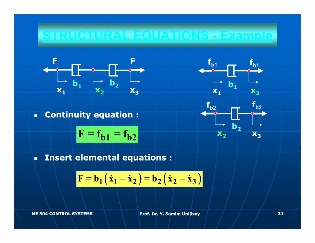
STRUCTURAL EQUATIONS STRUCTURAL EQUATIONS -- ExampleExample
FF fb1 fb1
x3
b2x1 x2
b1
fb2 fb2
x1 x2
b1
Continuity equation :Continuity equation :
b1 b2F = f = f
fb2
x3
fb2
b2x2
Insert elemental equations :Insert elemental equations :
b1 b2F f f 32
( ) ( )1 1 2 2 2 3F = b x x = b x x− −
ME 304 CONTROL SYSTEMSME 304 CONTROL SYSTEMS Prof. Dr. Y. Samim ÜnlüsoyProf. Dr. Y. Samim Ünlüsoy 3131
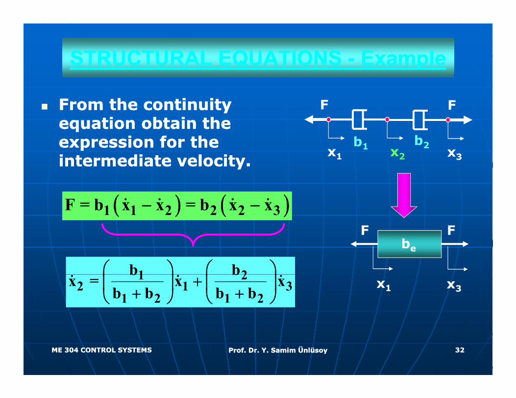
STRUCTURAL EQUATIONS STRUCTURAL EQUATIONS -- ExampleExample
From the continuity From the continuity equation obtain the equation obtain the
FFequation obtain the equation obtain the expression for the expression for the intermediate velocity. intermediate velocity.
x3
b2x1 x2
b1
( ) ( )1 1 2 2 2 3F = b x x = b x x− −
1 2b b⎛ ⎞ ⎛ ⎞⎜ ⎟ ⎜ ⎟
F Fbe
1 22 1 3
1 2 1 2
b bx = x x
b b b b⎛ ⎞ ⎛ ⎞
+⎜ ⎟ ⎜ ⎟+ +⎝ ⎠ ⎝ ⎠x3x1
ME 304 CONTROL SYSTEMSME 304 CONTROL SYSTEMS Prof. Dr. Y. Samim ÜnlüsoyProf. Dr. Y. Samim Ünlüsoy 3232
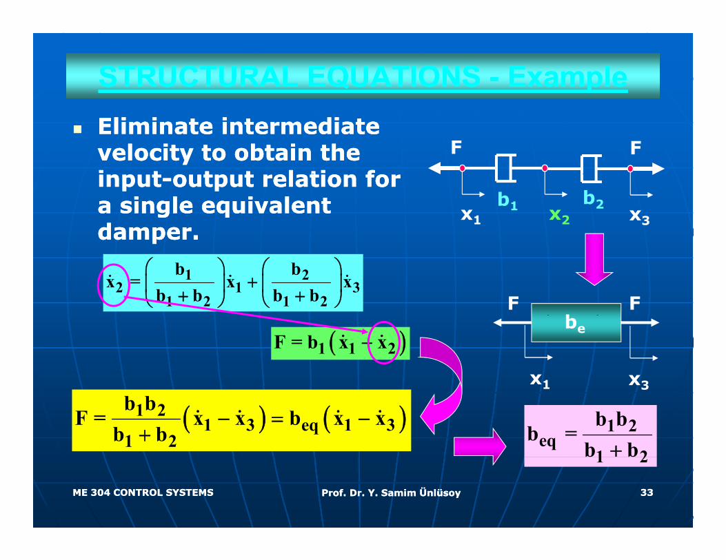
STRUCTURAL EQUATIONS STRUCTURAL EQUATIONS -- ExampleExampleEliminate intermediate Eliminate intermediate velocity to obtain the velocity to obtain the i ti t t t l ti f t t l ti f
FF
inputinput--output relation for output relation for a single equivalent a single equivalent damper.damper.
x3
b2x1 x2
b1
1 22 1 3
1 2 1 2
b bx = x x
b b b b⎛ ⎞ ⎛ ⎞
+⎜ ⎟ ⎜ ⎟+ +⎝ ⎠ ⎝ ⎠ F Fb
x3x1
be( )1 1 2F = b x x−
( ) ( )1 21 3 eq 1 3
1 2
b bF = x x b x x
b b− = −
+
31
1 2eq
1 2
b bb =
b b+
ME 304 CONTROL SYSTEMSME 304 CONTROL SYSTEMS Prof. Dr. Y. Samim ÜnlüsoyProf. Dr. Y. Samim Ünlüsoy 3333
1 2b b
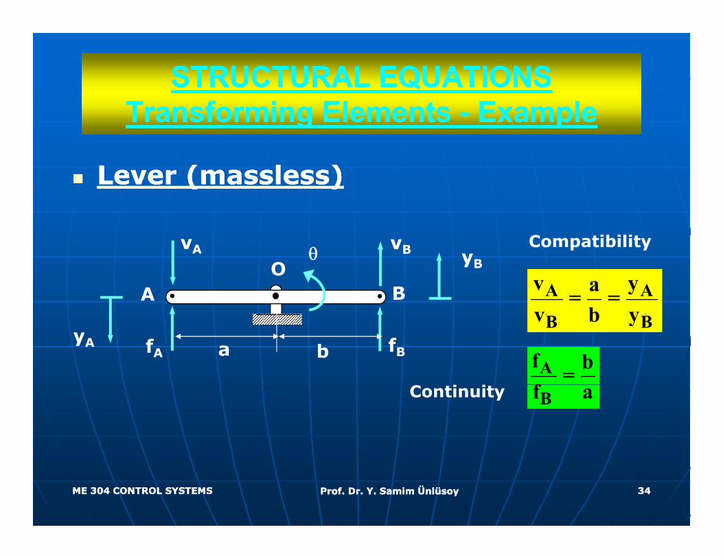
STRUCTURAL EQUATIONSSTRUCTURAL EQUATIONST f i El tT f i El t E lE lTransforming Elements Transforming Elements -- ExampleExample
Lever (massless)Lever (massless)Lever (massless)Lever (massless)
vv Compatibility
A Av ya= =v b y
vBvA
OBA
θ yB
Compatibility
B Bv b y
Af b=f
b fBfAyA a
Bf aContinuity
ME 304 CONTROL SYSTEMSME 304 CONTROL SYSTEMS Prof. Dr. Y. Samim ÜnlüsoyProf. Dr. Y. Samim Ünlüsoy 3434
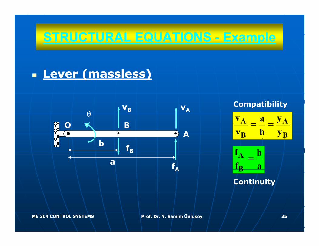
STRUCTURAL EQUATIONS STRUCTURAL EQUATIONS -- ExampleExample
Lever (massless)Lever (massless)Lever (massless)Lever (massless)
vv Compatibility
A A
B B
v ya= =v b y
vAvB
OA
Bθ
p y
A
B
f b=f afA
fB
a
b
BA
Continuity
ME 304 CONTROL SYSTEMSME 304 CONTROL SYSTEMS Prof. Dr. Y. Samim ÜnlüsoyProf. Dr. Y. Samim Ünlüsoy 3535
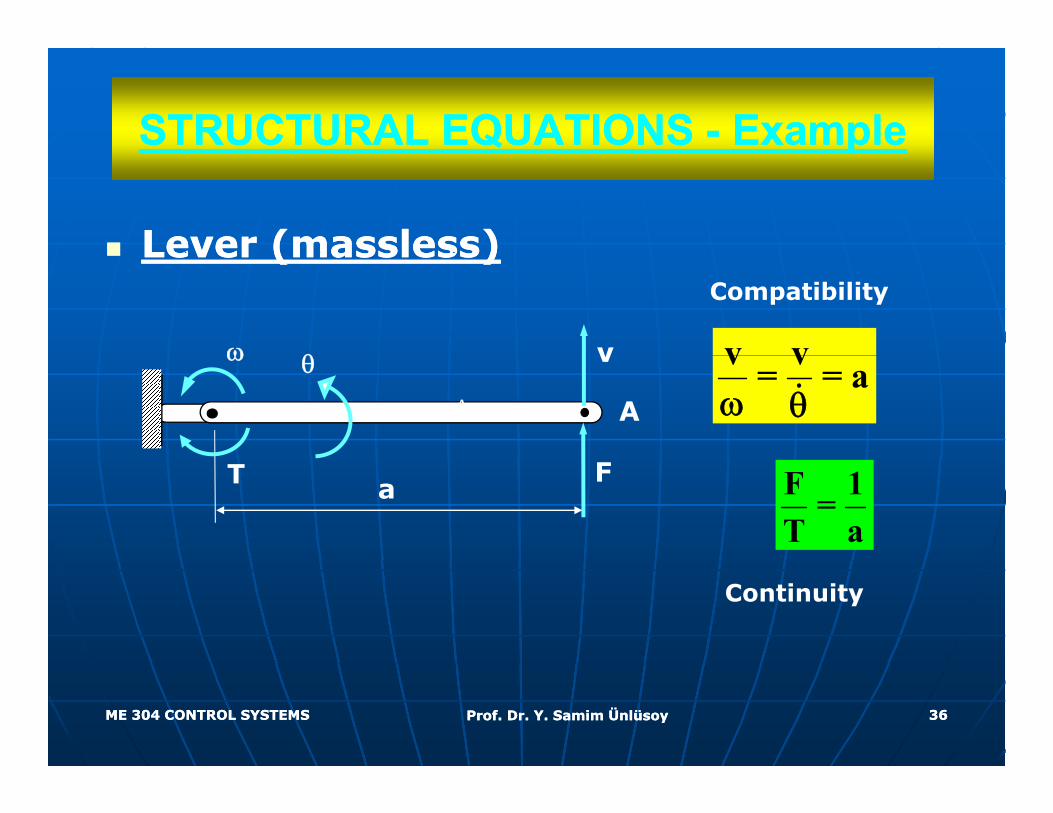
STRUCTURAL EQUATIONS STRUCTURAL EQUATIONS -- ExampleExamplepp
Lever (massless)Lever (massless)Lever (massless)Lever (massless)
v vvω θ
Compatibility
v v= = aω θA
v
A
ω θ
F 1=T a
aFT
Continuity
ME 304 CONTROL SYSTEMSME 304 CONTROL SYSTEMS Prof. Dr. Y. Samim ÜnlüsoyProf. Dr. Y. Samim Ünlüsoy 3636
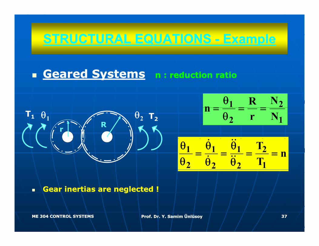
STRUCTURAL EQUATIONS STRUCTURAL EQUATIONS -- ExampleExamplepp
Geared SystemsGeared Systems n : reduction ration : reduction ratioGeared SystemsGeared Systems n : reduction ration : reduction ratio
1 2NRnθ
= = =2 1
nr N
= = =θT2θ1T1 θ2
rR
1 1 1 2
2 12 2
Tn
Tθ θ θ
= = = =θ θ θ
Gear inertias are neglected !Gear inertias are neglected !
ME 304 CONTROL SYSTEMSME 304 CONTROL SYSTEMS Prof. Dr. Y. Samim ÜnlüsoyProf. Dr. Y. Samim Ünlüsoy 3737
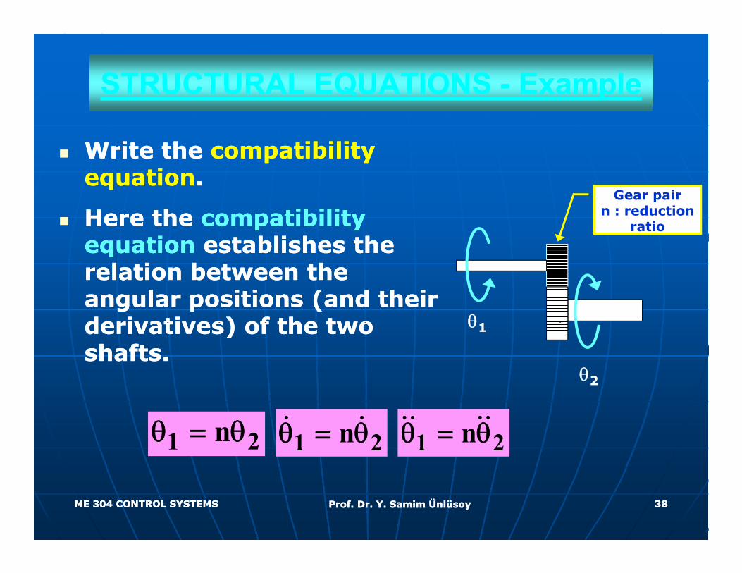
STRUCTURAL EQUATIONS STRUCTURAL EQUATIONS -- ExampleExample
Write the Write the compatibility compatibility equationequationequationequation..
Here the Here the compatibility compatibility equationequation establishes the establishes the
Gear pairn : reduction
ratio
equationequation establishes the establishes the relation between the relation between the angular positions (and their angular positions (and their derivatives) of the two derivatives) of the two θ1derivatives) of the two derivatives) of the two shafts.shafts.
θ2
θ1
1 2nθ = θ1 2nθ = θ 1 2nθ = θ
ME 304 CONTROL SYSTEMSME 304 CONTROL SYSTEMS Prof. Dr. Y. Samim ÜnlüsoyProf. Dr. Y. Samim Ünlüsoy 3838
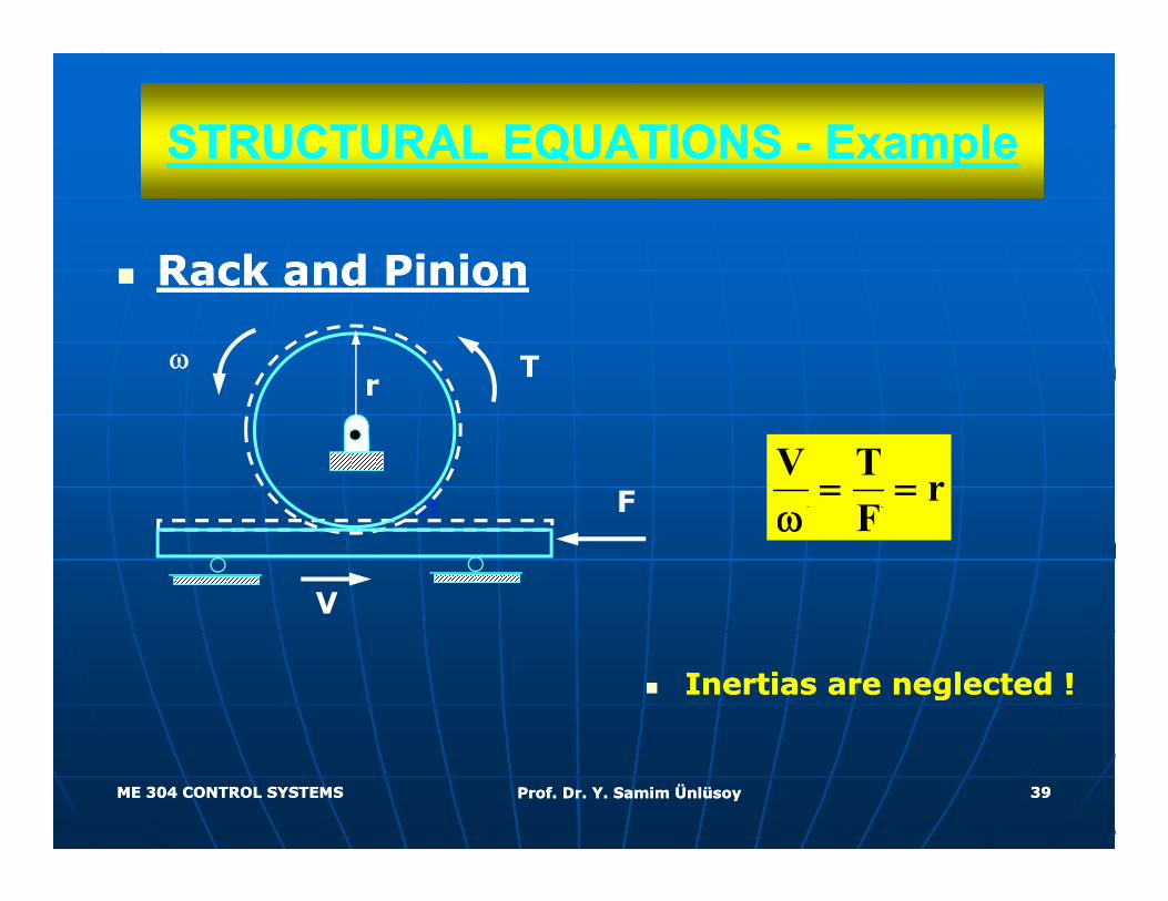
STRUCTURAL EQUATIONS STRUCTURAL EQUATIONS -- ExampleExamplepp
Rack and PinionRack and PinionRack and PinionRack and Pinion
rω T
V T rF
= =Fn
r
Fω
V
Fn
Inertias are neglected !Inertias are neglected !
ME 304 CONTROL SYSTEMSME 304 CONTROL SYSTEMS Prof. Dr. Y. Samim ÜnlüsoyProf. Dr. Y. Samim Ünlüsoy 3939
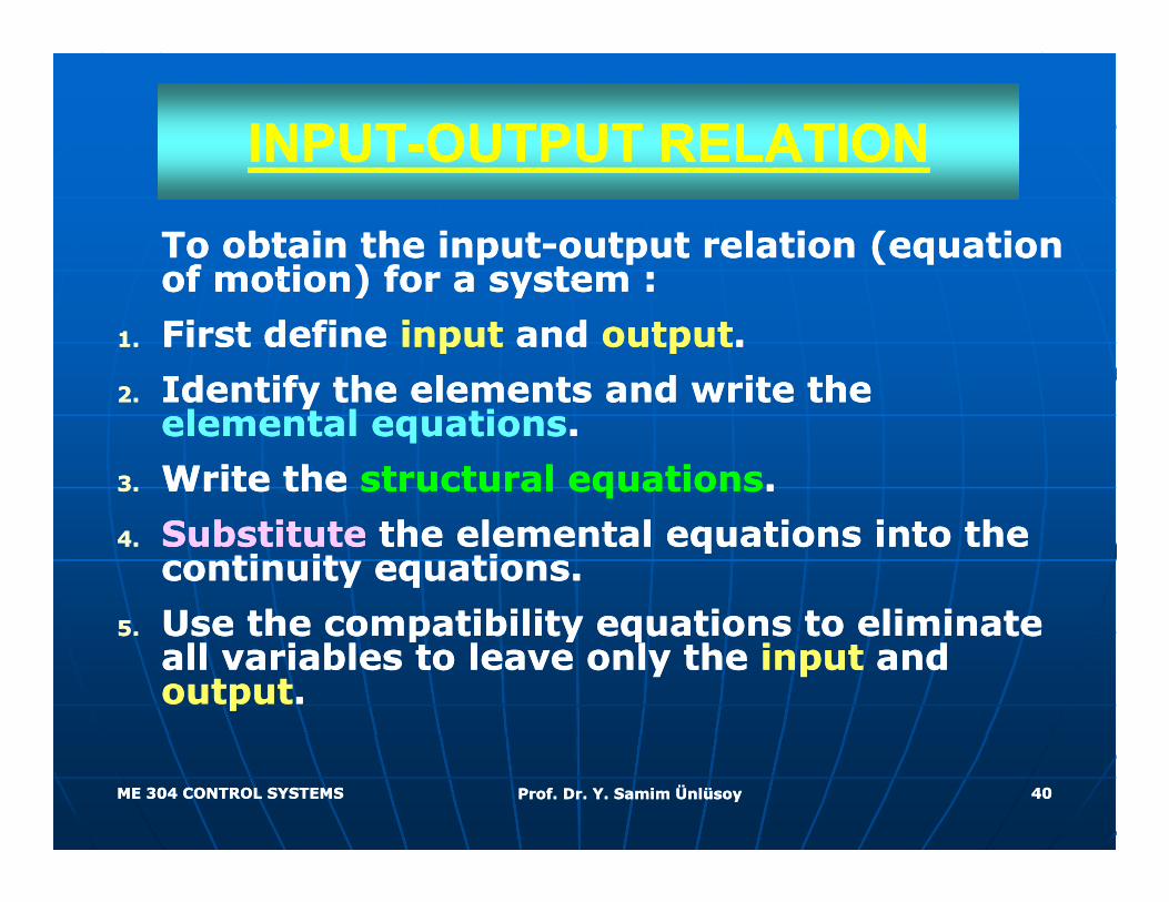
INPUTINPUT--OUTPUT RELATIONOUTPUT RELATION
To obtain the inputTo obtain the input--output relation (equation output relation (equation of motion) for a system :of motion) for a system :of motion) for a system :of motion) for a system :
1.1. First define First define inputinput and and outputoutput..
22 Identify the elements and write the Identify the elements and write the 2.2. Identify the elements and write the Identify the elements and write the elemental equationselemental equations..
3.3. Write the Write the structural equationsstructural equations. .
4.4. SubstituteSubstitute the elemental equations into the the elemental equations into the continuity equations.continuity equations.
55 Use the compatibility equations to eliminate Use the compatibility equations to eliminate 5.5. Use the compatibility equations to eliminate Use the compatibility equations to eliminate all variables to leave only the all variables to leave only the inputinput and and outputoutput..
ME 304 CONTROL SYSTEMSME 304 CONTROL SYSTEMS Prof. Dr. Y. Samim ÜnlüsoyProf. Dr. Y. Samim Ünlüsoy 4040
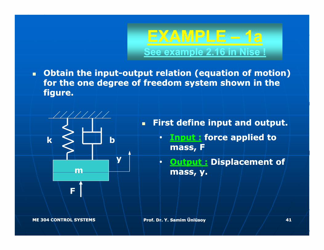
EXAMPLE EXAMPLE –– 1a1aSee example 2.16 in Nise !See example 2.16 in Nise !
Obtain the inputObtain the input--output relation (equation of motion) output relation (equation of motion) for the one degree of freedom system shown in the for the one degree of freedom system shown in the figure.figure.
k b
First define input and output.First define input and output.
•• Input :Input : force applied to force applied to k b
my
pp ppppmass, Fmass, F
•• Output :Output : Displacement of Displacement of mass ymass ym
F
mass, y.mass, y.
ME 304 CONTROL SYSTEMSME 304 CONTROL SYSTEMS Prof. Dr. Y. Samim ÜnlüsoyProf. Dr. Y. Samim Ünlüsoy 4141
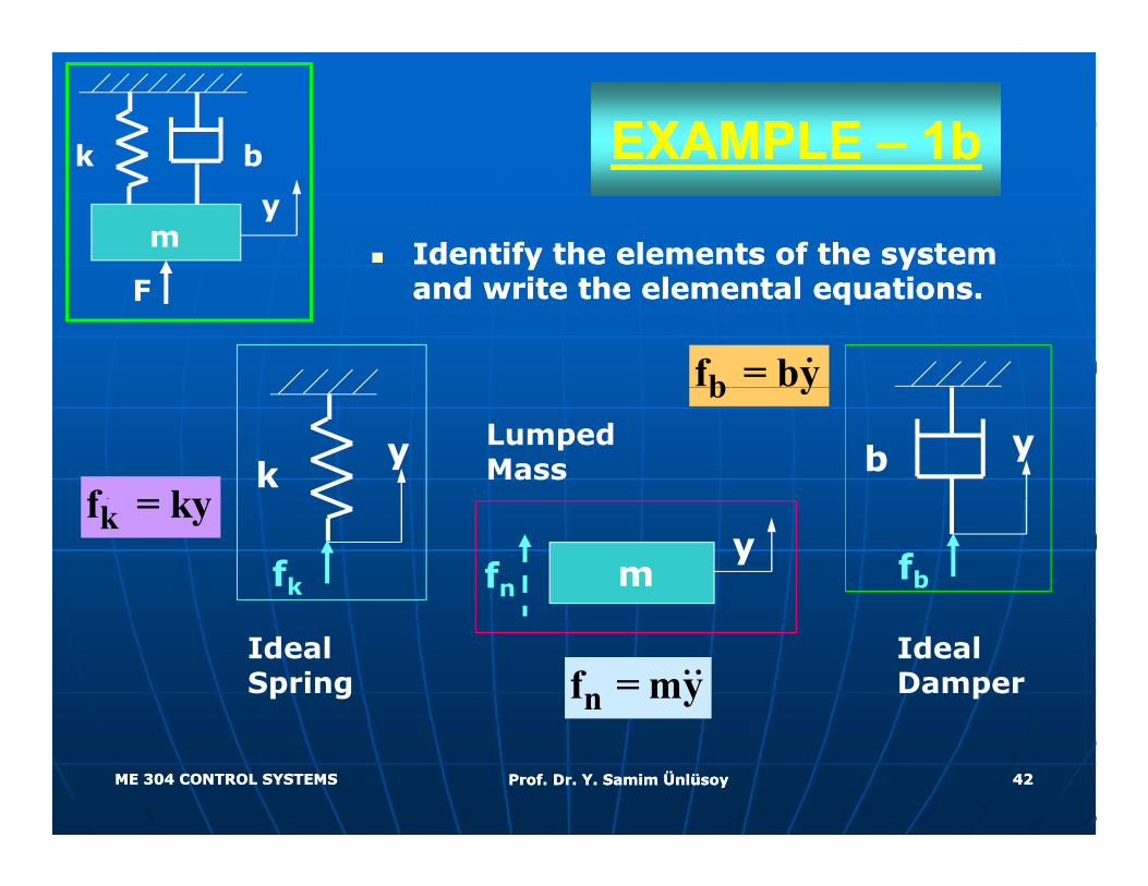
EXAMPLE EXAMPLE –– 1b1bk b
Identify the elements of the system Identify the elements of the system
k b
my
and write the elemental equations.and write the elemental equations.F
bf = by
f ky
b y
ky b yLumped
Mass
kf = ky
fkfb
yfn m
nf = myIdeal Spring
Ideal Damper
ME 304 CONTROL SYSTEMSME 304 CONTROL SYSTEMS Prof. Dr. Y. Samim ÜnlüsoyProf. Dr. Y. Samim Ünlüsoy 4242
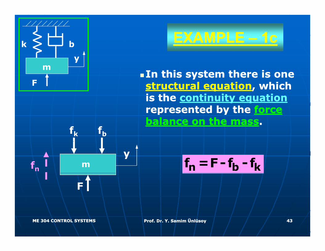
EXAMPLE EXAMPLE –– 1c1ck b
In this system there is one In this system there is one
k b
my
yystructural equationstructural equation, which , which is the is the continuity equationcontinuity equationrepresented by the represented by the force force
F
represented by the represented by the force force balance on the massbalance on the mass..
fbfk
n b kf =F-f - fmy
fn
F
ME 304 CONTROL SYSTEMSME 304 CONTROL SYSTEMS Prof. Dr. Y. Samim ÜnlüsoyProf. Dr. Y. Samim Ünlüsoy 4343
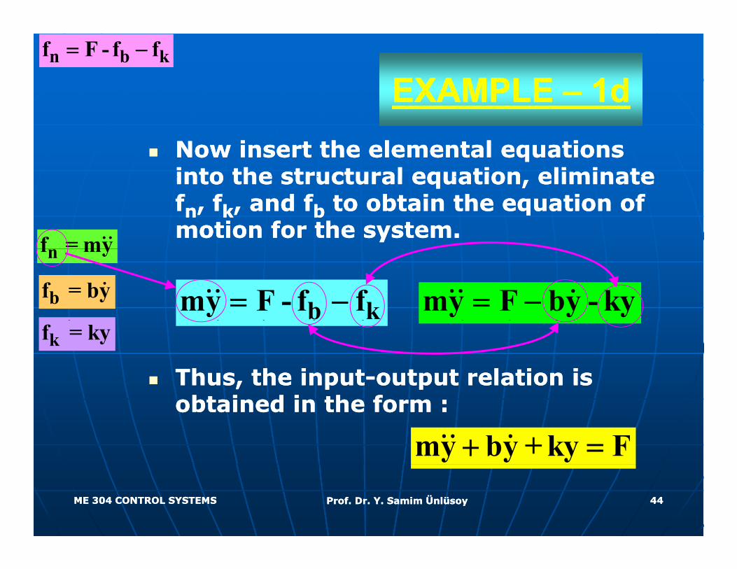
EXAMPLE EXAMPLE –– 1d1dn b kf F - f f= −
Now insert the elemental equations Now insert the elemental equations into the structural equation eliminate into the structural equation eliminate into the structural equation, eliminate into the structural equation, eliminate ffnn, f, fkk, and f, and fbb to obtain the equation of to obtain the equation of motion for the system.motion for the system.f = my
bf = byb kmy F - f f= −
nf my
my F by - ky= −
Thus, the inputThus, the input--output relation is output relation is
kf = ky
obtained in the form :obtained in the form :
my by +ky F+ =
ME 304 CONTROL SYSTEMSME 304 CONTROL SYSTEMS Prof. Dr. Y. Samim ÜnlüsoyProf. Dr. Y. Samim Ünlüsoy 4444
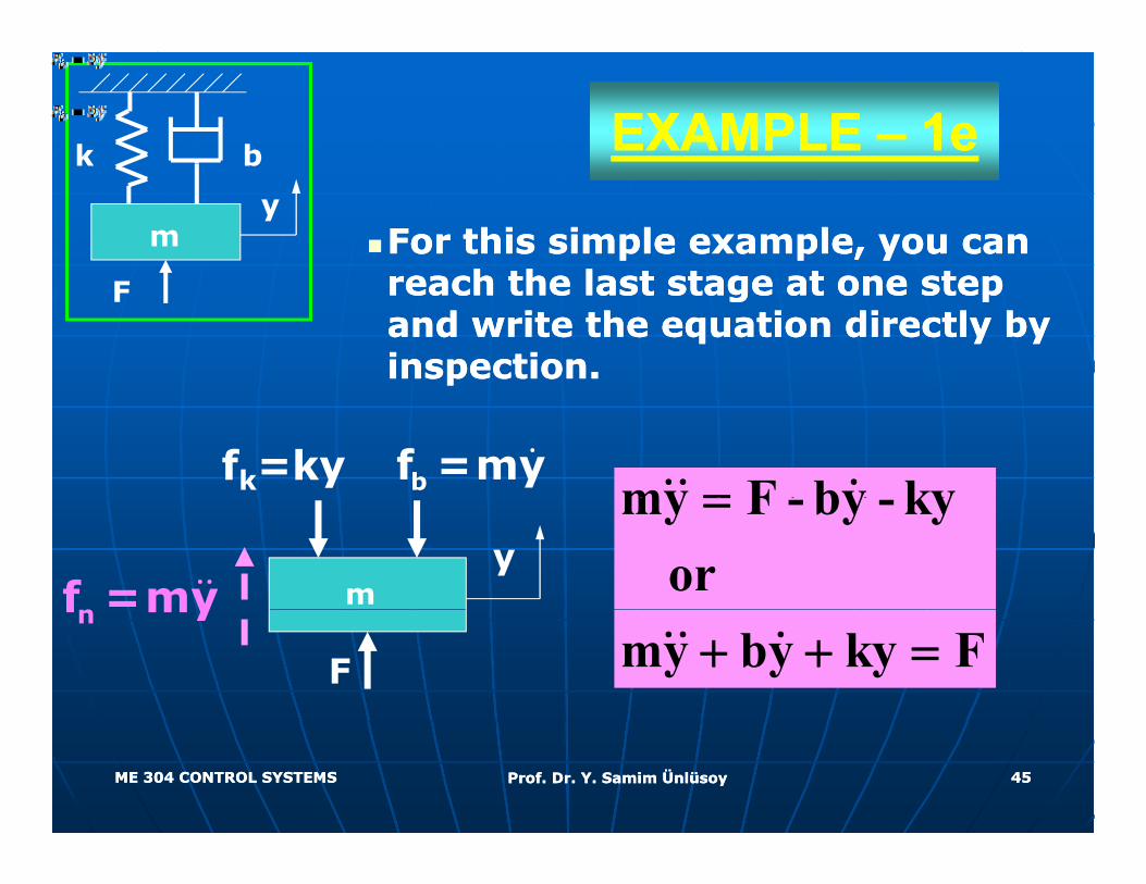
EXAMPLE EXAMPLE –– 1e1ek b
For this simple example, you can For this simple example, you can h th l t t t t h th l t t t t
k b
my
reach the last stage at one step reach the last stage at one step and write the equation directly by and write the equation directly by inspection.inspection.
F
my F by ky=fk=ky bf =my
my F - by - kyor=
my
nf =mymy by ky F+ + =F
nf my
ME 304 CONTROL SYSTEMSME 304 CONTROL SYSTEMS Prof. Dr. Y. Samim ÜnlüsoyProf. Dr. Y. Samim Ünlüsoy 4545
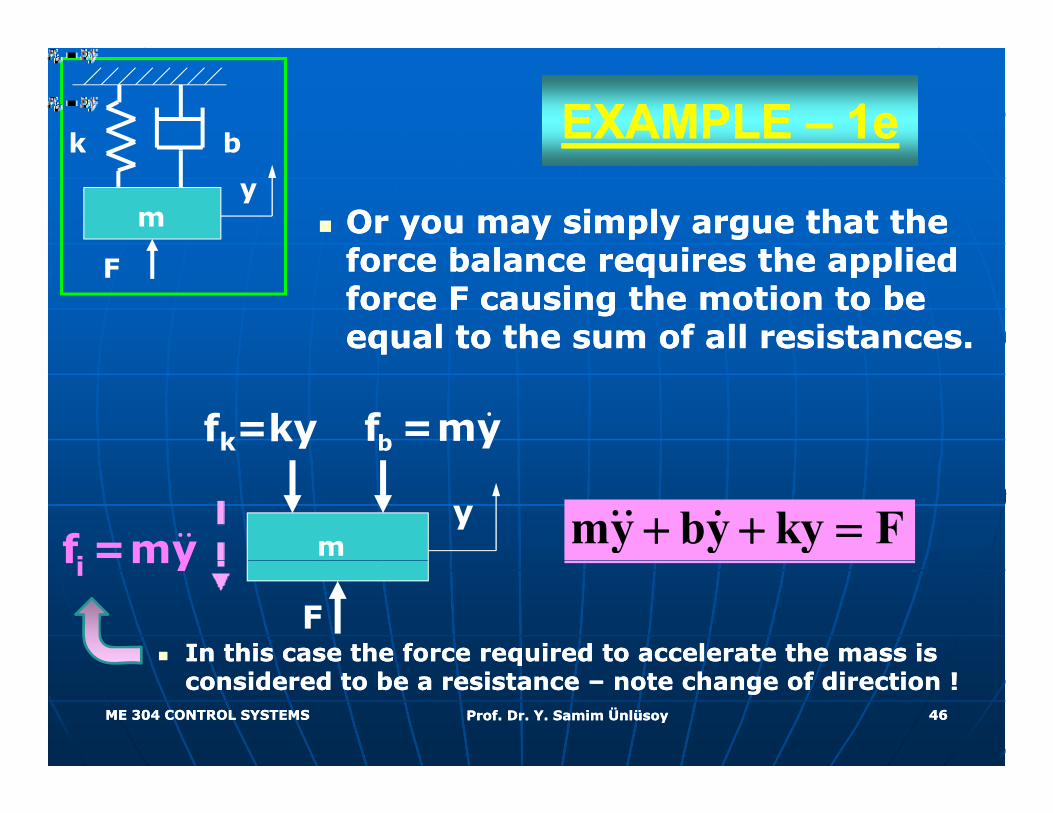
EXAMPLE EXAMPLE –– 1e1ek b
Or you may simply argue that the Or you may simply argue that the f b l i th li d f b l i th li d
k b
my
force balance requires the applied force balance requires the applied force F causing the motion to be force F causing the motion to be equal to the sum of all resistances.equal to the sum of all resistances.
F
fk=ky bf =my
my by ky F+ + =my
if =my
F
if my
In this case the force required to accelerate the mass is In this case the force required to accelerate the mass is
ME 304 CONTROL SYSTEMSME 304 CONTROL SYSTEMS Prof. Dr. Y. Samim ÜnlüsoyProf. Dr. Y. Samim Ünlüsoy 4646
qqconsidered to be a resistance considered to be a resistance –– note change of direction !note change of direction !
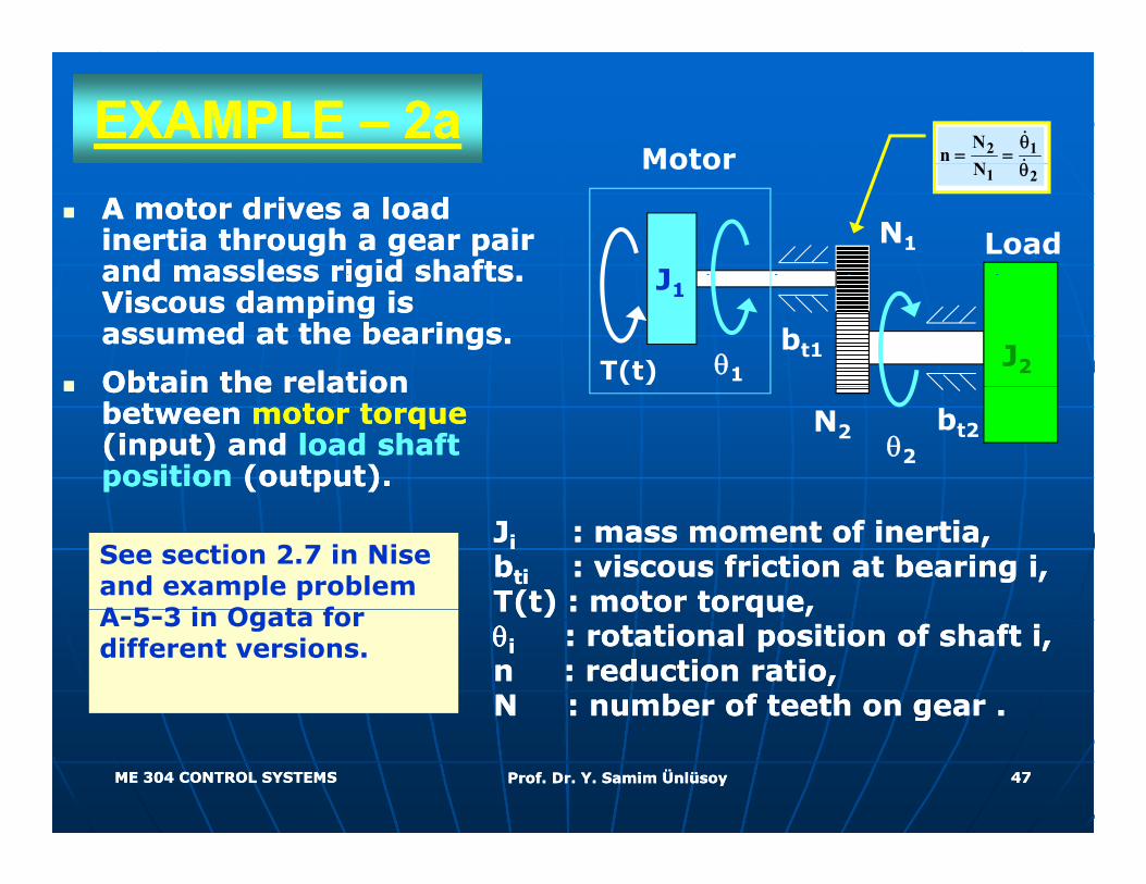
EXAMPLE EXAMPLE –– 2a2aMotor 2 1N
nN
θ= =
θ
A motor drives a load A motor drives a load inertia through a gear pair inertia through a gear pair and massless rigid shafts and massless rigid shafts
Motor
J
1 2N θ
LoadN1
and massless rigid shafts. and massless rigid shafts. Viscous damping is Viscous damping is assumed at the bearings. assumed at the bearings.
Obtain the relation Obtain the relation bt1θ1T(t)
J1
J2Obtain the relation Obtain the relation between between motor torquemotor torque(input) and (input) and load shaft load shaft position position (output).(output).
bt2θ2
N2
JJii : mass moment of inertia,: mass moment of inertia,bbtiti : viscous friction at bearing i,: viscous friction at bearing i,T(t) : motor torque,T(t) : motor torque,
See section 2.7 in Nise and example problem A 5 3 i O t f T(t) : motor torque,T(t) : motor torque,
θθii : rotational position of shaft i,: rotational position of shaft i,n : reduction ratio,n : reduction ratio,N : number of teeth on gear .N : number of teeth on gear .
A-5-3 in Ogata for different versions.
ME 304 CONTROL SYSTEMSME 304 CONTROL SYSTEMS Prof. Dr. Y. Samim ÜnlüsoyProf. Dr. Y. Samim Ünlüsoy 4747
gg
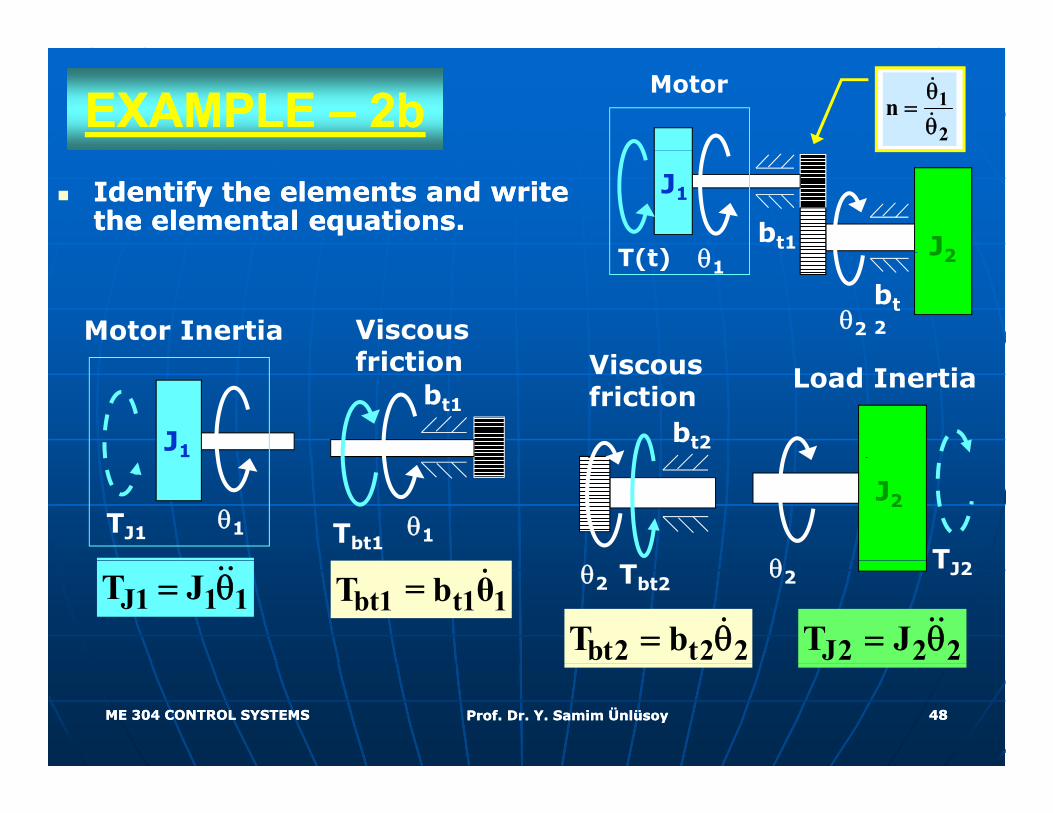
EXAMPLE EXAMPLE –– 2b2bMotor 1
2n
θ=θ
Identify the elements and write Identify the elements and write the elemental equations.the elemental equations. bt1
T(t)
J1
J2θbt2θ2
T(t) J2θ1
Motor Inertia Viscous f i ti Vi
J1
Load Inertiabt1
friction
bt2
Viscous friction
θ1TJ1
J2
θ Tθ1Tbt1
J1 1 1T J= θ
J2 2 2T J= θ
θ2TJ2
bt1 t1 1T = b θ
bt2 t2 2T b= θ
θ2 Tbt2
ME 304 CONTROL SYSTEMSME 304 CONTROL SYSTEMS Prof. Dr. Y. Samim ÜnlüsoyProf. Dr. Y. Samim Ünlüsoy 4848

EXAMPLE EXAMPLE –– 2c2cTo write the To write the structural equationsstructural equations, the , the system is divided into two parts at the system is divided into two parts at the
C tibilit tiC tibilit ti
gear pair.gear pair.Motor
Compatibility equationCompatibility equation(gear pair):(gear pair):
θ θJ1
and/orand/or1 2θ =nθ
θ θ
θ1
J2
1 2θ =nθθ2
2
Load
ME 304 CONTROL SYSTEMSME 304 CONTROL SYSTEMS Prof. Dr. Y. Samim ÜnlüsoyProf. Dr. Y. Samim Ünlüsoy 4949
Load
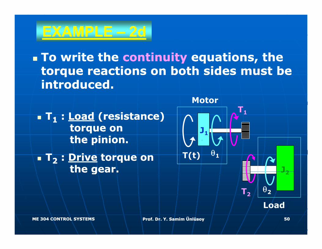
EXAMPLE EXAMPLE –– 2d2dTo write theTo write the continuitycontinuity equations, the equations, the torque reactions on both sides must be torque reactions on both sides must be introduced.introduced.
MotorT
TT11 : : LoadLoad (resistance) (resistance) torque on torque on the pinionthe pinion
J1
T1
the pinion.the pinion.
TT22 : : DriveDrive torque on torque on the gear.the gear.
θ1
J2
T(t)
the gear.the gear.
θ2
J2
L d
T2
ME 304 CONTROL SYSTEMSME 304 CONTROL SYSTEMS Prof. Dr. Y. Samim ÜnlüsoyProf. Dr. Y. Samim Ünlüsoy 5050
Load
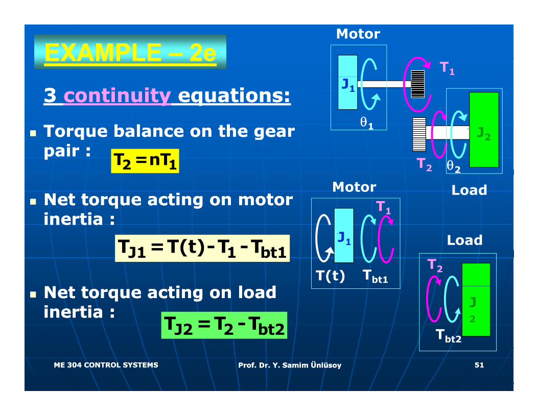
EXAMPLE EXAMPLE –– 2e2eT1
Motor
3 3 continuitycontinuity equations:equations:
Torque balance on the gear Torque balance on the gear
J1
θ1 JTorque balance on the gear Torque balance on the gear pair :pair :
2 1T =nT
1
T2 θ2
J2
Net torque acting on motor Net torque acting on motor inertia :inertia :
Motor
J
T1
Load
i l di l d
J1 1 bt1T =T(t)-T -T
T(t)
J1
Tbt1
Load
T2
Net torque acting on load Net torque acting on load inertia :inertia :
J2 2 bt2T =T -TJ2
Tbt2
ME 304 CONTROL SYSTEMSME 304 CONTROL SYSTEMS Prof. Dr. Y. Samim ÜnlüsoyProf. Dr. Y. Samim Ünlüsoy 5151
Tbt2
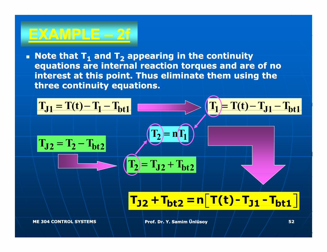
EXAMPLE EXAMPLE –– 2f2fNote that TNote that T11 and Tand T22 appearing in the continuity appearing in the continuity equations are internal reaction torques and are of no equations are internal reaction torques and are of no interest at this point. Thus eliminate them using the interest at this point. Thus eliminate them using the interest at this point. Thus eliminate them using the interest at this point. Thus eliminate them using the three continuity equations.three continuity equations.
J1 1 bt1T T(t) T T= − − 1 J1 bt1T T(t) T T= − −J1 1 bt1( ) 1 J1 bt1( )
T T T 2 1T nT=J2 2 bt2T T T= −
2 J2 bt2T T T= +
⎡ ⎤⎣ ⎦J2 bt2 J1 bt1T +T =n T(t)-T -T
ME 304 CONTROL SYSTEMSME 304 CONTROL SYSTEMS Prof. Dr. Y. Samim ÜnlüsoyProf. Dr. Y. Samim Ünlüsoy 5252
⎣ ⎦J2 bt2 J1 bt1( )
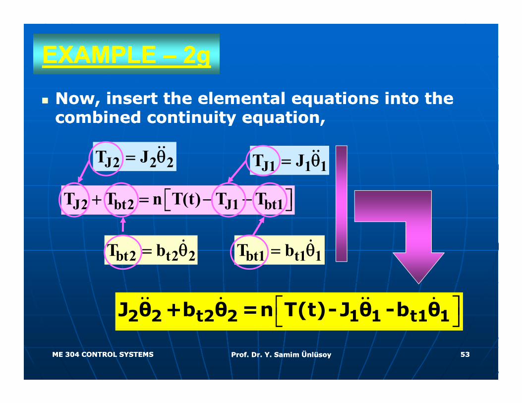
EXAMPLE EXAMPLE –– 2g2gNow, insert the elemental equations into the Now, insert the elemental equations into the combined continuity equation, combined continuity equation, y q ,y q ,
J1 1 1T J= θJ2 2 2T J= θ
J2 bt2 J1 bt1T T n T(t) T T+ = − −⎡ ⎤⎣ ⎦
bt1 t1 1T b= θbt2 t2 2T b= θ
⎡ ⎤⎣ ⎦2 2 t2 2 1 1 t1 1J θ +b θ =n T(t)-J θ -b θ
ME 304 CONTROL SYSTEMSME 304 CONTROL SYSTEMS Prof. Dr. Y. Samim ÜnlüsoyProf. Dr. Y. Samim Ünlüsoy 5353
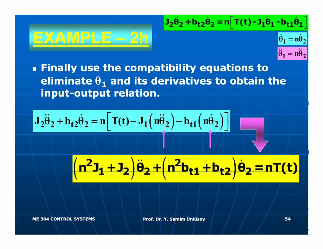
EXAMPLE EXAMPLE –– 2h2h 1 2nθ = θ
⎡ ⎤⎣ ⎦2 2 t2 2 1 1 t1 1J θ +b θ =n T(t)-J θ -b θ
Finally use the compatibility equations to Finally use the compatibility equations to li i li i θθ d i d i i b i h d i d i i b i h
1 2nθ = θ
eliminate eliminate θθ11 and its derivatives to obtain the and its derivatives to obtain the inputinput--output relation. output relation.
( ) ( )2 2 t2 2 1 2 t1 2J b n T(t) J n b n⎡ ⎤θ + θ = − θ − θ⎣ ⎦
( ) ( )2 21 2 2 t1 t2 2n J +J θ + n b +b θ =nT(t)( ) ( )1 2 2 t1 t2 2θ θ ( )
ME 304 CONTROL SYSTEMSME 304 CONTROL SYSTEMS Prof. Dr. Y. Samim ÜnlüsoyProf. Dr. Y. Samim Ünlüsoy 5454
ReadingReadinggg
Ni Ni S ti 2 5 2 6 2 7 2 10S ti 2 5 2 6 2 7 2 10Nise Nise –– Sections 2.5, 2.6, 2.7, 2.10Sections 2.5, 2.6, 2.7, 2.10and 2.11 and 2.11
(M d li l ) (M d li l ) (Modeling only) (Modeling only)
Ogata Ogata –– Section 3.1, Example problems Section 3.1, Example problems AA--33--14, 15, 14, 15, and and 161633 , 5,, 5, a da d 66
ME 304 CONTROL SYSTEMSME 304 CONTROL SYSTEMS Prof. Dr. Y. Samim ÜnlüsoyProf. Dr. Y. Samim Ünlüsoy 5555