
MC462 Quad Balanced - hifipower.grhifipower.gr/wp-content/uploads/MC462_manual.pdf · ° § µ ±...
20
• ΜΑΡΝΗ 8 ΑΘΗΝΑ 10433 • ΤΗΛ. 210 3845676 – 210 3845272 FAX. 210 3809747 • e-mail: [email protected] • McIntosh Laboratory, Inc. 2 Chambers Street Binghamton, New York 13903-2699 Phone: 607-723-3512 www.mcintoshlabs.com MC462 Quad Balanced Power Amplifier Owner’s Manual
Transcript of MC462 Quad Balanced - hifipower.grhifipower.gr/wp-content/uploads/MC462_manual.pdf · ° § µ ±...
• ΜΑΡΝΗ 8 ΑΘΗΝΑ 10433 • ΤΗΛ. 210 3845676 – 210 3845272 FAX. 210 3809747 • e-mail: [email protected] •
McIntosh Laboratory, Inc. 2 Chambers Street Binghamton, New York 13903-2699 Phone: 607-723-3512 www.mcintoshlabs.com
MC462Quad Balanced
Power Amplifier
Owner’s Manual
• ΜΑΡΝΗ 8 ΑΘΗΝΑ 10433 • ΤΗΛ. 210 3845676 – 210 3845272 FAX. 210 3809747 • e-mail: [email protected] •
2
Your decision to own this McIntosh MC462 Stereo Power Amplifier with Quad Balanced Circuitry ranks you at the very top among discriminating music listen-ers. You now have “The Best.” The McIntosh dedica-tion to “Quality,” is assurance that you will receive many years of musical enjoyment from this unit.Please take a short time to read the information in this manual. We want you to be as familiar as pos-sible with all the features and functions of your new McIntosh.
Copyright 2018 © by McIntosh Laboratory, Inc.
Table of Contents
Thank You
Please Take A Moment
Technical AssistanceIf at any time you have questions about your McIntosh product, contact your McIntosh Dealer who is familiar with your McIntosh equipment and any other brands that may be part of your system. If you or your Dealer wish additional help concerning a suspected problem, you can receive technical assistance for all McIntosh products at:
McIntosh Laboratory, Inc.2 Chambers StreetBinghamton, New York 13903Phone: 607-723-3512Fax: 607-724-0549
Customer ServiceIf it is determined that your McIntosh product is in need of repair, you can return it to your Dealer. You can also return it to the McIntosh Laboratory Service Department. For assistance on factory repair return procedure, contact the McIntosh Service Department at:McIntosh Laboratory, Inc.2 Chambers StreetBinghamton, New York 13903Phone: 607-723-3515Fax: 607-723-1917
The serial number, purchase date and McIntosh Dealer name are important to you for possible insurance claim or future service. The spaces below have been provided for you to record that information:
Serial Number: _______________________________
Purchase Date: _______________________________
Dealer Name: ________________________________
Important Safety Information is supplied in a separate document “Important Additional Operation Information Guide”
Safety Instructions ..................................................... 2 (Separate Sheet) ................... Important Additional
Operation Information GuideThank You and Please Take a Moment ....................... 2Technical Assistance and Customer Service .............. 2Table of Contents ........................................................ 2General Information ................................................... 2Connector and Cable Information ..............................3Introduction .................................................................3Performance Features .................................................3Dimensions .................................................................5Installation ..................................................................6Rear Panel Connections and Switch ...........................7Output Terminals and How to Connect .................. 8-9Output Terminals and How to Connect for Bi-Amp ......................................................... 10-11Front Panel Displays and Controls ............................12How to Operate .........................................................13Technical Description .......................................... 14-17Specifications ............................................................ 18Packing Instruction ................................................... 19
1. For additional connection information, refer to theowner’s manual(s) for any component(s) connectedto the MC462.
2. The MC462 mutes the speaker output for approxi-mately two seconds when first turned on.
3. For the best performance and safety it is importantto always match the impedance of the Loudspeakerto the Power Amplifier connections. Refer to “Howto Connect” pages 7 thru 10.
Note: The impedance of a Loudspeaker actually var-ies as the Loudspeaker reproduces different frequencies. As a result, the nominal impedance rating of the Loudspeaker (usually measured at a midrange frequency) might not always agree with the impedance of the Loudspeaker at low frequencies where the greatest amount of power is required. Contact the Loudspeaker Manufac-turer for additional information about the actual impedance of the Loudspeaker before connecting it to the McIntosh MC462.
4. In the event the MC462 over heats, due to improperventilation and/or high ambient temperature, the protection circuits will activate. The Front Panel Power Guard LED will continuously indicate ON and the audio will be muted. When the MC462 has returned to a safe operating temperature, normal operation will resume.
5. When discarding the unit, comply with local rulesor regulations. Batteries should never be thrown away or incinerated but disposed of in accordance with the local regulations concerning battery disposal.
6. For additional information on the MC462 andother McIntosh Products please visit the McIntosh Website at www.mcintoshlabs.com.
General Information
• ΜΑΡΝΗ 8 ΑΘΗΝΑ 10433 • ΤΗΛ. 210 3845676 – 210 3845272 FAX. 210 3809747 • e-mail: [email protected] •
3
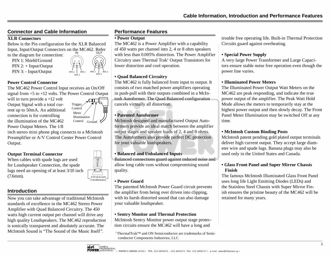
XLR ConnectorsBelow is the Pin configuration for the XLR Balanced Input, Input/Output Connectors on the MC462. Refer to the diagram for connection: PIN 1: Shield/Ground PIN 2: + Input/Output PIN 3: - Input/Output
Power Control ConnectorThe MC462 Power Control Input receives an On/Off signal from +5 to +12 volts. The Power Control Output will in turn provide a +12 volt Output Signal with a total cur-rent up to 50mA. An additional connection is for controlling the illumination of the MC462 Power Output Meters. The 1/8 inch stereo mini phone plug connects to a McIntosh Preamplifier or A/V Control Center Power Control Output.
Output Terminal ConnectorWhen cables with spade lugs are used for Loudspeaker Connection, the spade lugs need an opening of at least 3/10 inch (7.6mm).
Cable Information, Introduction and Performance Features
Connector and Cable Information
IntroductionNow you can take advantage of traditional McIntosh standards of excellence in the MC462 Stereo Power Amplifier with Quad Balanced Circuitry. The 450 watts high current output per channel will drive any high quality Loudspeakers. The MC462 reproduction is sonically transparent and absolutely accurate. The McIntosh Sound is “The Sound of the Music Itself”.
Performance Features• Power OutputThe MC462 is a Power Amplifier with a capability of 450 watts per channel into 2, 4 or 8 ohm speakers with less than 0.005% distortion. The Power Amplifier Circuitry uses Thermal Trak1 Output Transistors for lower distortion and cool operation.
• Quad Balanced CircuitryThe MC462 is fully balanced from input to output. It consists of two matched power amplifiers operating in push-pull with their outputs combined in a McIn-tosh Autoformer. The Quad Balanced configuration cancels virtually all distortion.
• Patented AutoformerMcIntosh designed and manufactured Output Auto-formers provide an ideal match between the amplifier output stages and speaker loads of 2, 4 and 8 ohms. The Autoformers also provide perfect DC protection for your valuable loudspeakers.
• Balanced and Unbalanced InputsBalanced connections guard against induced noise and allow long cable runs without compromising sound quality.
• Power GuardThe patented McIntosh Power Guard circuit prevents the amplifier from being over driven into clipping, with its harsh distorted sound that can also damage your valuable loudspeaker.
• Sentry Monitor and Thermal ProtectionMcIntosh Sentry Monitor power output stage protec-tion circuits ensure the MC462 will have a long and
trouble free operating life. Built-in Thermal Protection Circuits guard against overheating.
• Special Power SupplyA very large Power Transformer and Large Capaci-tors ensure stable noise free operation even though the power line varies.
• Illuminated Power MetersThe Illuminated Power Output Watt Meters on the MC462 are peak responding, and indicate the true power output of the amplifier. The Peak Watt Hold Mode allows the meters to temporarily stay at the highest power output and then slowly decay. The Front Panel Meter Illumination may be switched Off at any time.
• McIntosh Custom Binding PostsMcIntosh patent pending gold plated output terminals deliver high current output. They accept large diam-eter wire and spade lugs. Banana plugs may also be used only in the United States and Canada.
• Glass Front Panel and Super Mirror ChassisFinish
The famous McIntosh Illuminated Glass Front Panel uses long life Light Emitting Diodes (LEDs) and the Stainless Steel Chassis with Super Mirror Fin-ish ensures the pristine beauty of the MC462 will be retained for many years.
Trigger Control
Ground
MeterIlluminationControl
1 ThermalTrak™ and ON Semiconductor are trademarks of Semi-conductor Components Industries, LLC
PIN 1 PIN 2PIN 3
PIN 2 PIN 1 PIN 3
OUTIN
3/10 of an inch(7.6millimeters)
• ΜΑΡΝΗ 8 ΑΘΗΝΑ 10433 • ΤΗΛ. 210 3845676 – 210 3845272 FAX. 210 3809747 • e-mail: [email protected] •
4
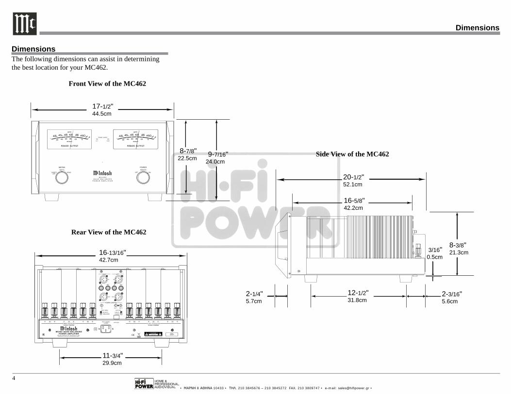
DimensionsThe following dimensions can assist in determining the best location for your MC462.
Dimensions
Front View of the MC462
Rear View of the MC462
Side View of the MC462
17-1/2"44.5cm
8-7/8"22.5cm 9-7/16"
24.0cm
11-3/4"29.9cm
16-13/16"42.7cm
3/16"0.5cm
DISABLED
16-5/8"42.2cm
2-1/4"5.7cm
8-3/8"21.3cm
2-3/16"5.6cm
20-1/2"52.1cm
12-1/2"31.8cm
• ΜΑΡΝΗ 8 ΑΘΗΝΑ 10433 • ΤΗΛ. 210 3845676 – 210 3845272 FAX. 210 3809747 • e-mail: [email protected] •
5
Installation
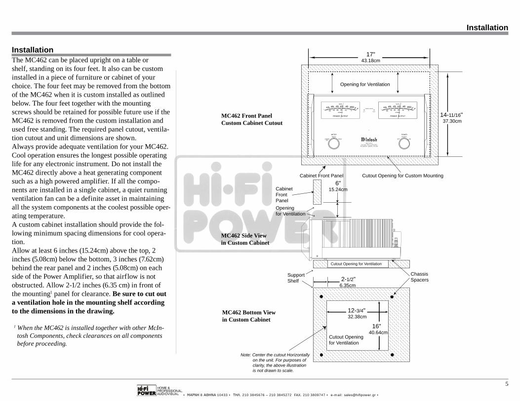
InstallationThe MC462 can be placed upright on a table or shelf, standing on its four feet. It also can be custom installed in a piece of furniture or cabinet of your choice. The four feet may be removed from the bottom of the MC462 when it is custom installed as outlined below. The four feet together with the mounting screws should be retained for possible future use if the MC462 is removed from the custom installation and used free standing. The required panel cutout, ventila-tion cutout and unit dimensions are shown.Always provide adequate ventilation for your MC462. Cool operation ensures the longest possible operating life for any electronic instrument. Do not install the MC462 directly above a heat generating component such as a high powered amplifier. If all the compo-nents are installed in a single cabinet, a quiet running ventilation fan can be a definite asset in maintaining all the system components at the coolest possible oper-ating temperature.A custom cabinet installation should provide the fol-lowing minimum spacing dimensions for cool opera-tion.Allow at least 6 inches (15.24cm) above the top, 2 inches (5.08cm) below the bottom, 3 inches (7.62cm) behind the rear panel and 2 inches (5.08cm) on each side of the Power Amplifier, so that airflow is not obstructed. Allow 2-1/2 inches (6.35 cm) in front of the mounting1 panel for clearance. Be sure to cut out a ventilation hole in the mounting shelf according to the dimensions in the drawing.
1 When the MC462 is installed together with other McIn-tosh Components, check clearances on all components before proceeding.
14-11/16"37.30cm
17"43.18cm
Cutout Opening for Custom Mounting
Opening for Ventilation
Cabinet Front Panel
MC462 Front Panel Custom Cabinet Cutout
Cutout Opening for Ventilation
SupportShelf
ChassisSpacers
MC462 Side Viewin Custom Cabinet
CabinetFrontPanel
Note: Center the cutout Horizontally on the unit. For purposes of clarity, the above illustration is not drawn to scale.
MC462 Bottom Viewin Custom Cabinet
6"15.24cm
Openingfor Ventilation
12-3/4"32.38cm
Cutout Openingfor Ventilation
16"40.64cm
2-1/2"6.35cm

• ΜΑΡΝΗ 8 ΑΘΗΝΑ 10433 • ΤΗΛ. 210 3845676 – 210 3845272 FAX. 210 3809747 • e-mail: [email protected] •
6
DISABLED
Caution: The Loudspeaker Negative Connections are above chassis ground. Do not combine any connections together, ground them or connect with another MC462.
Connect the MC462 power cord to a live AC outlet. Refer to the rear panel to determine the correct voltage
POWER CONTROL IN receives turn On/Off signals from a McIntosh component.POWER CONTROL OUT 1 and 2 send turn On/Off signals to the next McIn-tosh Component
Unbalanced INput (RIGHT Channel) for an audio cable from a Preamplifier or A/V Con-trol Center audio output.Unbalanced OUTput (RIGHT Channel) for an audio cable to the next Power Amplifier Input
INPUT MODE switch se-lects between BALANCED or UNBALANCED Inputs
Balanced INputs (LEFT and RIGHT Channels) for audio cables from a Pre-amplifier or A/V Control Center audio output
Balanced OUTputs (LEFT and RIGHT Channels) for an audio cable to the next Power Ampli-fier Input
RIGHT OUTPUTS Connection for a 2 ohm Loudspeaker
Rear Panel Connections and Switch
Fuse holder, refer to information on the rear panel of your MC462 to determine the correct fuse size and rating
RIGHT OUTPUTS Connection for a 4 ohm Loudspeaker
RIGHT OUTPUTS Connection for an 8 ohm Loudspeaker
LEFT OUTPUTS Connection for an 8 ohm Loudspeaker
LEFT OUTPUTS Connection for a 4 ohm Loudspeaker
LEFT OUTPUTS Connections for a 2 ohm Loudspeaker
Unbalanced INput (LEFT Channel) for an au-dio cable from a Preamplifier or A/V Control Center audio output.Unbalanced OUTput (LEFT Channel) for an audio cable to the next Power Amplifier Input
AUTO OFF Mode Switch selects be-tween ENABLED or DISABLED
• ΜΑΡΝΗ 8 ΑΘΗΝΑ 10433 • ΤΗΛ. 210 3845676 – 210 3845272 FAX. 210 3809747 • e-mail: [email protected] •
7
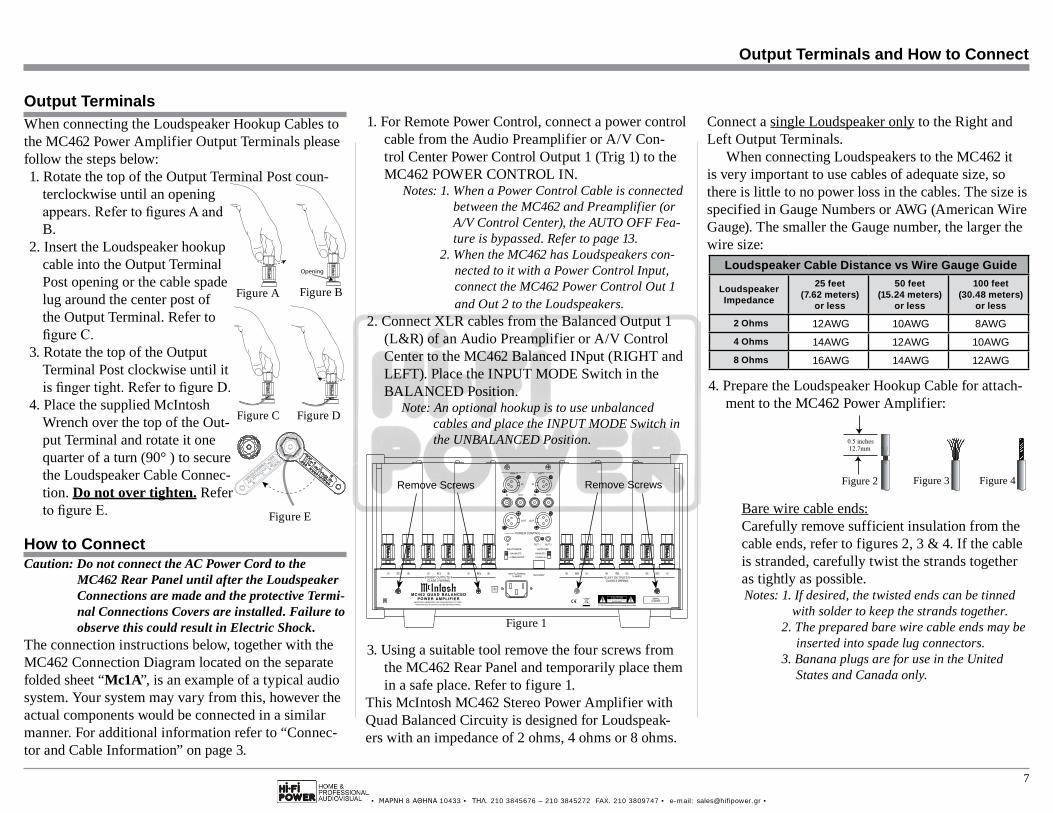
1. For Remote Power Control, connect a power control cable from the Audio Preamplifier or A/V Con-trol Center Power Control Output 1 (Trig 1) to the MC462 POWER CONTROL IN.
Notes: 1. When a Power Control Cable is connected between the MC462 and Preamplifier (or A/V Control Center), the AUTO OFF Fea-ture is bypassed. Refer to page 13.
2. When the MC462 has Loudspeakers con-nected to it with a Power Control Input, connect the MC462 Power Control Out 1 and Out 2 to the Loudspeakers.
2. Connect XLR cables from the Balanced Output 1 (L&R) of an Audio Preamplifier or A/V Control Center to the MC462 Balanced INput (RIGHT and LEFT). Place the INPUT MODE Switch in the BALANCED Position.
Note: An optional hookup is to use unbalanced cables and place the INPUT MODE Switch in the UNBALANCED Position.
3. Using a suitable tool remove the four screws from the MC462 Rear Panel and temporarily place them in a safe place. Refer to figure 1.
This McIntosh MC462 Stereo Power Amplifier with Quad Balanced Circuity is designed for Loudspeak-ers with an impedance of 2 ohms, 4 ohms or 8 ohms.
When connecting the Loudspeaker Hookup Cables to the MC462 Power Amplifier Output Terminals please follow the steps below:1. Rotate the top of the Output Terminal Post coun-
terclockwise until an opening appears. Refer to figures A and B.
2. Insert the Loudspeaker hookup cable into the Output Terminal Post opening or the cable spade lug around the center post of the Output Terminal. Refer to figure C.
3. Rotate the top of the Output Terminal Post clockwise until it is finger tight. Refer to figure D.
4. Place the supplied McIntosh Wrench over the top of the Out-put Terminal and rotate it one quarter of a turn (90° ) to secure the Loudspeaker Cable Connec-tion. Do not over tighten. Refer to figure E.
Caution: Do not connect the AC Power Cord to the MC462 Rear Panel until after the Loudspeaker Connections are made and the protective Termi-nal Connections Covers are installed. Failure to observe this could result in Electric Shock.
The connection instructions below, together with the MC462 Connection Diagram located on the separate folded sheet “Mc1A”, is an example of a typical audio system. Your system may vary from this, however the actual components would be connected in a similar manner. For additional information refer to “Connec-tor and Cable Information” on page 3.
Connect a single Loudspeaker only to the Right and Left Output Terminals.
When connecting Loudspeakers to the MC462 it is very important to use cables of adequate size, so there is little to no power loss in the cables. The size is specified in Gauge Numbers or AWG (American Wire Gauge). The smaller the Gauge number, the larger the wire size:
Loudspeaker Cable Distance vs Wire Gauge Guide
LoudspeakerImpedance
25 feet(7.62 meters)
or less
50 feet(15.24 meters)
or less
100 feet(30.48 meters)
or less
2 Ohms 12AWG 10AWG 8AWG4 Ohms 14AWG 12AWG 10AWG8 Ohms 16AWG 14AWG 12AWG
4. Prepare the Loudspeaker Hookup Cable for attach-ment to the MC462 Power Amplifier:
Bare wire cable ends:Carefully remove sufficient insulation from the cable ends, refer to figures 2, 3 & 4. If the cable is stranded, carefully twist the strands together as tightly as possible.Notes: 1. If desired, the twisted ends can be tinned
with solder to keep the strands together.2. The prepared bare wire cable ends may be
inserted into spade lug connectors.3. Banana plugs are for use in the United
States and Canada only.
How to Connect
Figure 2 Figure 3 Figure 4
DISABLED
Figure 1
Remove Screws Remove Screws
Output Terminals
Figure A
Opening
Figure B
Figure C Figure D
Figure E
Output Terminals and How to Connect
• ΜΑΡΝΗ 8 ΑΘΗΝΑ 10433 • ΤΗΛ. 210 3845676 – 210 3845272 FAX. 210 3809747 • e-mail: [email protected] •
8
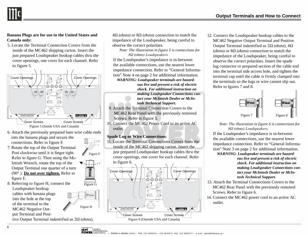
4Ω (ohms) or 8Ω (ohms) connection to match the impedance of the Loudspeaker, being careful to observe the correct polarities.
Note: The illustration in figure 5 is connections for 8Ω (ohms) Loudspeakers.
If the Loudspeaker’s impedance is in-between the available connections, use the nearest lower impedance connection. Refer to “General Informa-tion” Note 4 on page 2 for additional information.
WARNING: Loudspeaker terminals are hazard-ous live and present a risk of electric shock. For additional instruction on making Loudspeaker Connections con-tact your McIntosh Dealer or McIn-tosh Technical Support.
9. Attach the Terminal Connection Covers to the MC462 Rear Panel with the previously removed Screws. Refer to figure 5.
10. Connect the MC462 Power Cord to an active AC outlet.
Spade Lug or Wire Connections:11. Locate the Terminal Connections Covers from the
inside of the MC462 shipping carton. Insert the just prepared Loudspeaker hookup cables thru the cover openings, one cover for each channel. Refer to figure 6.
12. Connect the Loudspeaker hookup cables to the MC462 Negative Output Terminal and Positive Output Terminal indentified as 2Ω (ohms), 4Ω (ohms) or 8Ω (ohms) connection to match the impedance of the Loudspeaker, being careful to observe the correct polarities. Insert the spade lug connector or prepared section of the cable end into the terminal side access hole, and tighten the terminal cap until the cable is firmly clamped into the terminals so the lugs or wire cannot slip out. Refer to fgures 7 and 8.
Note: The illustration in figure 6 is connections for 8Ω (ohms) Loudspeakers.
If the Loudspeaker’s impedance is in-between the available connections, use the nearest lower impedance connection. Refer to “General Informa-tion” Note 3 on page 2 for additional information.
WARNING: Loudspeaker terminals are hazard-ous live and present a risk of electric shock. For additional instruction on making Loudspeaker Connections con-tact your McIntosh Dealer or McIn-tosh Technical Support.
13. Attach the Terminal Connections Covers to the MC462 Rear Panel with the previously removed Screws. Refer to figure 6.
14. Connect the MC462 power cord to an active AC outlet.
Output Terminals and How to Connect
Banana Plugs are for use in the United States and Canada only:5. Locate the Terminal Connection Covers from the
inside of the MC462 shipping carton. Insert the just prepared Loudspeaker hookup cables thru the cover openings, one cover for each channel. Refer to figure 5.
6. Attach the previously prepared bare wire cable ends into the banana plugs and secure the connections. Refer to figure F.
7. Rotate the top of the Output Terminal Post clockwise until it is finger tight. Refer to figure G. Then using the Mc-Intosh Wrench, rotate the top of the Output Terminal one quarter of a turn (90° ). Do not over tighten. Refer to figure E.
8. Referring to figure H, connect the Loudspeaker hookup cables with banana plugs into the hole at the top of the terminal to the MC462 Negative Out-put Terminal and Posi-tive Output Terminal indentified as 2Ω (ohms),
Figure 7 Figure 8
Figure 5 (Inside USA and Canada)
DISABLED
Cover Openings Cover Openings
Cover Screws Cover Screws
Figure 6 (Outside USA and Canada)
DISABLED
Cover Openings Cover Openings
Cover Screws Cover Screws
Figure F Figure H
Figure F Figure H
Figure G
• ΜΑΡΝΗ 8 ΑΘΗΝΑ 10433 • ΤΗΛ. 210 3845676 – 210 3845272 FAX. 210 3809747 • e-mail: [email protected] •
9
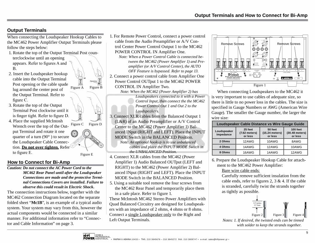
1. For Remote Power Control, connect a power control cable from the Audio Preamplifier or A/V Con-trol Center Power Control Output 1 to the MC462 POWER CONTROL IN Amplifier One.
Note: When a Power Control Cable is connected be-tween the MC462 (Power Amplifier 1) and Pre-amplifier (or A/V Control Center), the AUTO OFF Feature is bypassed. Refer to page 13.
2. Connect a power control cable from Amplifier One Power Control OUTput 1 to the MC462 POWER CONTROL IN Amplifier Two.
Note: When the MC462 (Power Amplifier 2) has Loudspeakers connected to it with a Power Control Input, then connect the the MC462 Power Control Out 1 and Out 2 to the Loudspeakers.
3. Connect XLR cables from the Balanced Output 1 (L&R) of an Audio Preamplifier or A/V Control Center to the MC462 (Power Amplifier 1) Bal-anced INput (RIGHT and LEFT). Place the INPUT MODE Switch in the BALANCED Position.
Note: An optional hookup is to use unbalanced cables and place the INPUT MODE Switch in the UNBALANCED Position.
4. Connect XLR cables from the MC462 (Power Amplifier 1) Audio Balanced OUTput (LEFT and RIGHT) to the MC462 (Power Amplifier 2) Bal-anced INput (RIGHT and LEFT). Place the INPUT MODE Switch in the BALANCED Position.
5. Using a suitable tool remove the four screws from the MC462 Rear Panel and temporarily place them in a safe place. Refer to figure 1.
These McIntosh MC462 Stereo Power Amplifiers with Quad Balanced Circuitry are designed for Loudspeak-ers with an impedance of 2 ohms, 4 ohms or 8 ohms. Connect a single Loudspeaker only to the Right and Left Output Terminals.
Caution: Do not connect the AC Power Cord to the MC462 Rear Panel until after the Loudspeaker Connections are made and the protective Termi-nal Connections Covers are installed. Failure to observe this could result in Electric Shock.
The connection instructions below, together with the MC462 Connection Diagram located on the separate folded sheet “Mc1B”, is an example of a typical audio system. Your system may vary from this, however the actual components would be connected in a similar manner. For additional information refer to “Connec-tor and Cable Information” on page 3.
When connecting Loudspeakers to the MC462 it is very important to use cables of adequate size, so there is little to no power loss in the cables. The size is specified in Gauge Numbers or AWG (American Wire Gauge). The smaller the Gauge number, the larger the wire size:
Loudspeaker Cable Distance vs Wire Gauge Guide
LoudspeakerImpedance
25 feet(7.62 meters)
or less
50 feet(15.24 meters)
or less
100 feet(30.48 meters)
or less
2 Ohms 12AWG 10AWG 8AWG4 Ohms 14AWG 12AWG 10AWG8 Ohms 16AWG 14AWG 12AWG
6. Prepare the Loudspeaker Hookup Cable for attach-ment to the MC462 Power Amplifier:
Bare wire cable ends:Carefully remove sufficient insulation from the cable ends, refer to figures 2, 3 & 4. If the cable is stranded, carefully twist the strands together as tightly as possible.
Notes: 1. If desired, the twisted ends can be tinned with solder to keep the strands together.
Figure 2 Figure 3 Figure 4
How to Connect for Bi-Amp
When connecting the Loudspeaker Hookup Cables to the MC462 Power Amplifier Output Terminals please follow the steps below:1. Rotate the top of the Output Terminal Post coun-
terclockwise until an opening appears. Refer to figures A and B.
2. Insert the Loudspeaker hookup cable into the Output Terminal Post opening or the cable spade lug around the center post of the Output Terminal. Refer to figure C.
3. Rotate the top of the Output Terminal Post clockwise until it is finger tight. Refer to figure D.
4. Place the supplied McIntosh Wrench over the top of the Out-put Terminal and rotate it one quarter of a turn (90° ) to secure the Loudspeaker Cable Connec-tion. Do not over tighten. Refer to figure E.
Output Terminals
Figure A
Opening
Figure B
Figure C Figure D
Figure E
Output Terminals and How to Connect for Bi-Amp
DISABLED
Figure 1
Remove Screws Remove Screws
• ΜΑΡΝΗ 8 ΑΘΗΝΑ 10433 • ΤΗΛ. 210 3845676 – 210 3845272 FAX. 210 3809747 • e-mail: [email protected] •
10
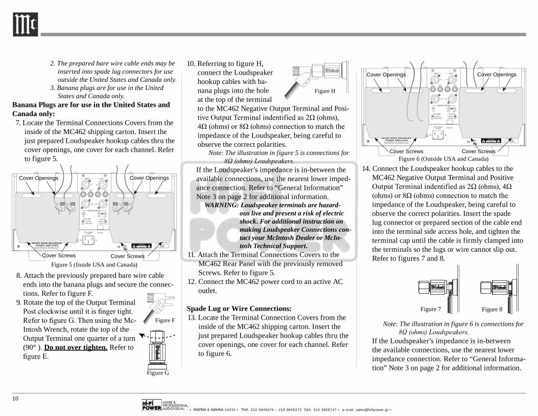
2. The prepared bare wire cable ends may be inserted into spade lug connectors for use outside the United States and Canada only.
3. Banana plugs are for use in the United States and Canada only.
Banana Plugs are for use in the United States and Canada only:7. Locate the Terminal Connections Covers from the
inside of the MC462 shipping carton. Insert the just prepared Loudspeaker hookup cables thru the cover openings, one cover for each channel. Refer to figure 5.
8. Attach the previously prepared bare wire cable ends into the banana plugs and secure the connec-tions. Refer to figure F.
9. Rotate the top of the Output Terminal Post clockwise until it is finger tight. Refer to figure G. Then using the Mc-Intosh Wrench, rotate the top of the Output Terminal one quarter of a turn (90° ). Do not over tighten. Refer to figure E.
14. Connect the Loudspeaker hookup cables to the MC462 Negative Output Terminal and Positive Output Terminal indentified as 2Ω (ohms), 4Ω (ohms) or 8Ω (ohms) connection to match the impedance of the Loudspeaker, being careful to observe the correct polarities. Insert the spade lug connector or prepared section of the cable end into the terminal side access hole, and tighten the terminal cap until the cable is firmly clamped into the terminals so the lugs or wire cannot slip out. Refer to figures 7 and 8.
Note: The illustration in figure 6 is connections for 8Ω (ohms) Loudspeakers.
If the Loudspeaker’s impedance is in-between the available connections, use the nearest lower impedance connection. Refer to “General Informa-tion” Note 3 on page 2 for additional information.
10. Referring to figure H, connect the Loudspeaker hookup cables with ba-nana plugs into the hole at the top of the terminal to the MC462 Negative Output Terminal and Posi-tive Output Terminal indentified as 2Ω (ohms), 4Ω (ohms) or 8Ω (ohms) connection to match the impedance of the Loudspeaker, being careful to observe the correct polarities.
Note: The illustration in figure 5 is connections for 8Ω (ohms) Loudspeakers.
If the Loudspeaker’s impedance is in-between the available connections, use the nearest lower imped-ance connection. Refer to “General Information” Note 3 on page 2 for additional information.
WARNING: Loudspeaker terminals are hazard-ous live and present a risk of electric shock. For additional instruction on making Loudspeaker Connections con-tact your McIntosh Dealer or McIn-tosh Technical Support.
11. Attach the Terminal Connections Covers to the MC462 Rear Panel with the previously removed Screws. Refer to figure 5.
12. Connect the MC462 power cord to an active AC outlet.
Spade Lug or Wire Connections:13. Locate the Terminal Connection Covers from the
inside of the MC462 shipping carton. Insert the just prepared Loudspeaker hookup cables thru the cover openings, one cover for each channel. Refer to figure 6.
Figure 7 Figure 8
Figure F Figure H
Figure F Figure H
Figure G
DISABLED
Figure 5 (Inside USA and Canada)
Cover Openings Cover Openings
Cover Screws Cover Screws
Figure 6 (Outside USA and Canada)
DISABLED
Cover Openings Cover Openings
Cover Screws Cover Screws
• ΜΑΡΝΗ 8 ΑΘΗΝΑ 10433 • ΤΗΛ. 210 3845676 – 210 3845272 FAX. 210 3809747 • e-mail: [email protected] •
11
Output Terminals and How to Connect for Bi-Amp
WARNING: Loudspeaker terminals are hazard-ous live and present a risk of electric shock. For additional instruction on making Loudspeaker Connections con-tact your McIntosh Dealer or McIn-tosh Technical Support.
15. Attach the Terminal Connections Covers to the MC462 Rear Panel with the previously removed Screws. Refer to figure 6.
16. Connect the MC462 power cord to an active AC outlet.
• ΜΑΡΝΗ 8 ΑΘΗΝΑ 10433 • ΤΗΛ. 210 3845676 – 210 3845272 FAX. 210 3809747 • e-mail: [email protected] •
12
Front Panel Displays and Controls
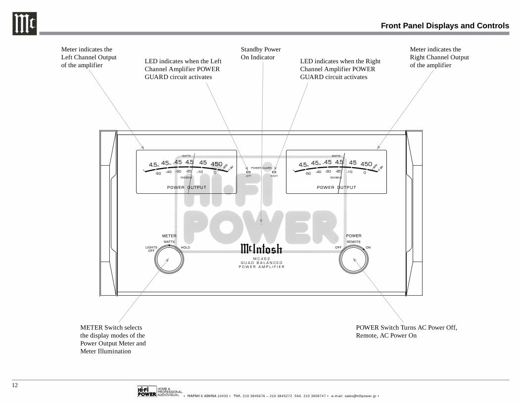
Standby Power On Indicator
POWER Switch Turns AC Power Off, Remote, AC Power On
METER Switch selects the display modes of the Power Output Meter and Meter Illumination
Meter indicates the Right Channel Output of the amplifierLED indicates when the Left
Channel Amplifier POWER GUARD circuit activates
Meter indicates the Left Channel Output of the amplifier LED indicates when the Right
Channel Amplifier POWER GUARD circuit activates
• ΜΑΡΝΗ 8 ΑΘΗΝΑ 10433 • ΤΗΛ. 210 3845676 – 210 3845272 FAX. 210 3809747 • e-mail: [email protected] •
13
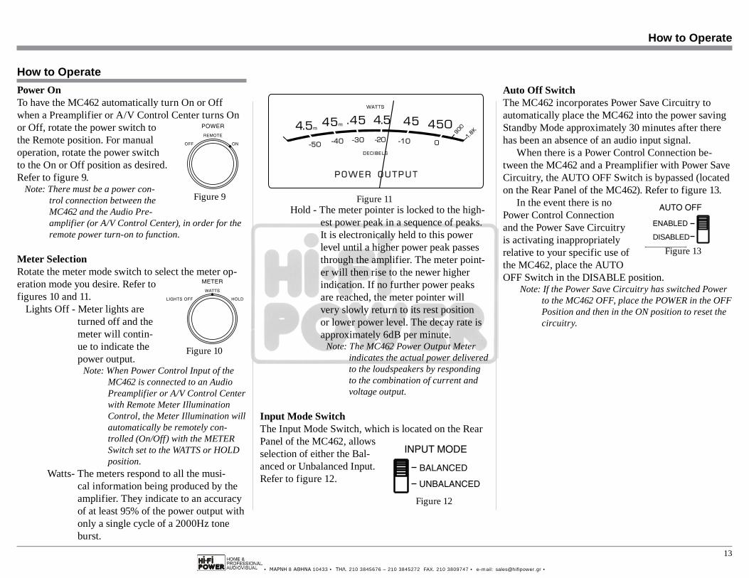
Hold - The meter pointer is locked to the high-est power peak in a sequence of peaks. It is electronically held to this power level until a higher power peak passes through the amplifier. The meter point-er will then rise to the newer higher indication. If no further power peaks are reached, the meter pointer will very slowly return to its rest position or lower power level. The decay rate is approximately 6dB per minute.
Note: The MC462 Power Output Meter indicates the actual power delivered to the loudspeakers by responding to the combination of current and voltage output.
Input Mode SwitchThe Input Mode Switch, which is located on the Rear Panel of the MC462, allows selection of either the Bal-anced or Unbalanced Input. Refer to figure 12.
Power OnTo have the MC462 automatically turn On or Off when a Preamplifier or A/V Control Center turns On or Off, rotate the power switch to the Remote position. For manual operation, rotate the power switch to the On or Off position as desired. Refer to figure 9.
Note: There must be a power con-trol connection between the MC462 and the Audio Pre-amplifier (or A/V Control Center), in order for the remote power turn-on to function.
Meter SelectionRotate the meter mode switch to select the meter op-eration mode you desire. Refer to figures 10 and 11.
Lights Off - Meter lights are turned off and the meter will contin-ue to indicate the power output.
Note: When Power Control Input of the MC462 is connected to an Audio Preamplifier or A/V Control Center with Remote Meter Illumination Control, the Meter Illumination will automatically be remotely con-trolled (On/Off) with the METER Switch set to the WATTS or HOLD position.
Watts- The meters respond to all the musi-cal information being produced by the amplifier. They indicate to an accuracy of at least 95% of the power output with only a single cycle of a 2000Hz tone burst.
Auto Off SwitchThe MC462 incorporates Power Save Circuitry to automatically place the MC462 into the power saving Standby Mode approximately 30 minutes after there has been an absence of an audio input signal.
When there is a Power Control Connection be-tween the MC462 and a Preamplifier with Power Save Circuitry, the AUTO OFF Switch is bypassed (located on the Rear Panel of the MC462). Refer to figure 13.
In the event there is no Power Control Connection and the Power Save Circuitry is activating inappropriately relative to your specific use of the MC462, place the AUTO OFF Switch in the DISABLE position.
Note: If the Power Save Circuitry has switched Power to the MC462 OFF, place the POWER in the OFF Position and then in the ON position to reset the circuitry.
How to Operate
How to Operate
Figure 9
Figure 10
Figure 11
Figure 13DISABLED
Figure 12
DISABLED
• ΜΑΡΝΗ 8 ΑΘΗΝΑ 10433 • ΤΗΛ. 210 3845676 – 210 3845272 FAX. 210 3809747 • e-mail: [email protected] •
14
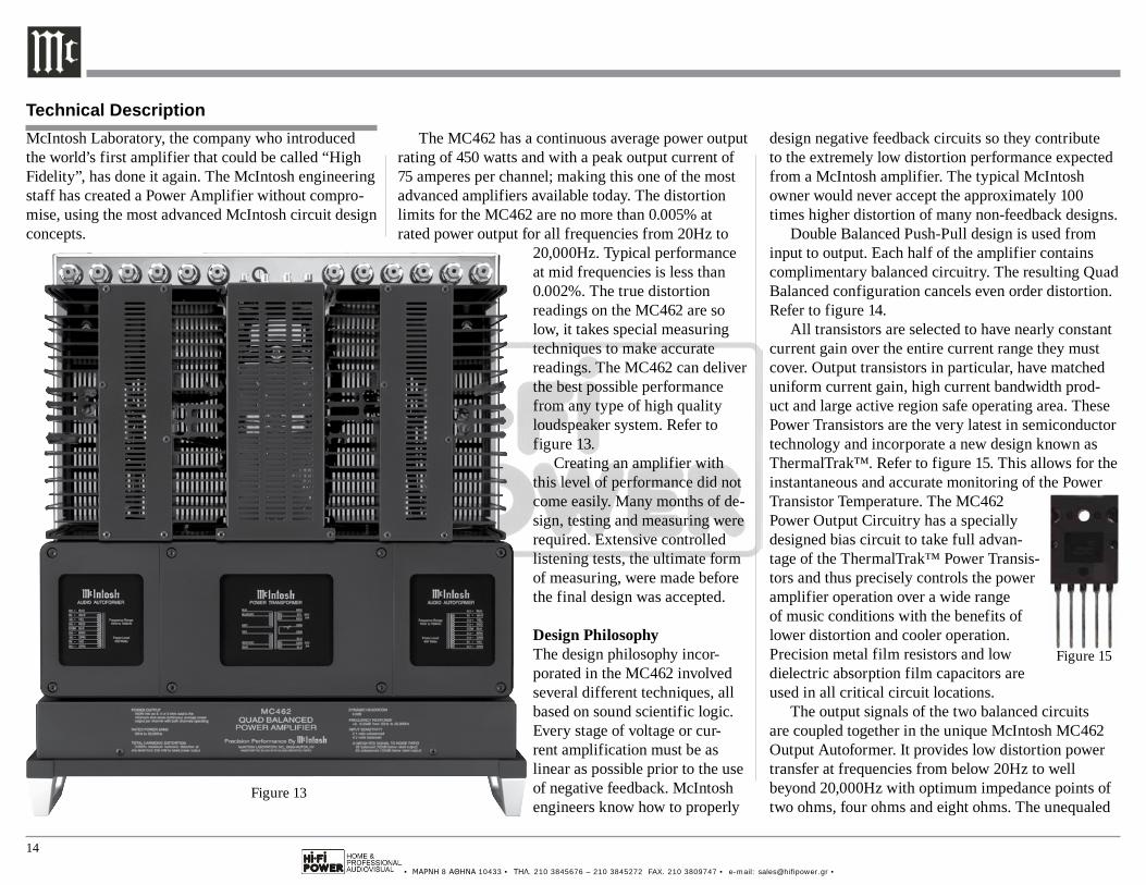
design negative feedback circuits so they contribute to the extremely low distortion performance expected from a McIntosh amplifier. The typical McIntosh owner would never accept the approximately 100 times higher distortion of many non-feedback designs.
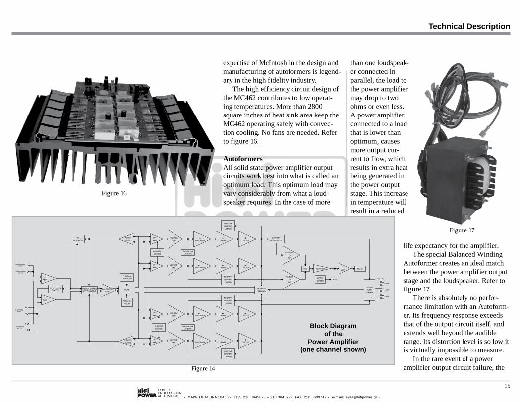
Double Balanced Push-Pull design is used from input to output. Each half of the amplifier contains complimentary balanced circuitry. The resulting Quad Balanced configuration cancels even order distortion. Refer to figure 14.
All transistors are selected to have nearly constant current gain over the entire current range they must cover. Output transistors in particular, have matched uniform current gain, high current bandwidth prod-uct and large active region safe operating area. These Power Transistors are the very latest in semiconductor technology and incorporate a new design known as ThermalTrak™. Refer to figure 15. This allows for the instantaneous and accurate monitoring of the Power Transistor Temperature. The MC462 Power Output Circuitry has a specially designed bias circuit to take full advan-tage of the ThermalTrak™ Power Transis-tors and thus precisely controls the power amplifier operation over a wide range of music conditions with the benefits of lower distortion and cooler operation. Precision metal film resistors and low dielectric absorption film capacitors are used in all critical circuit locations.
The output signals of the two balanced circuits are coupled together in the unique McIntosh MC462 Output Autoformer. It provides low distortion power transfer at frequencies from below 20Hz to well beyond 20,000Hz with optimum impedance points of two ohms, four ohms and eight ohms. The unequaled
Technical Description
Figure 15
McIntosh Laboratory, the company who introduced the world’s first amplifier that could be called “High Fidelity”, has done it again. The McIntosh engineering staff has created a Power Amplifier without compro-mise, using the most advanced McIntosh circuit design concepts.
The MC462 has a continuous average power output rating of 450 watts and with a peak output current of 75 amperes per channel; making this one of the most advanced amplifiers available today. The distortion limits for the MC462 are no more than 0.005% at rated power output for all frequencies from 20Hz to
20,000Hz. Typical performance at mid frequencies is less than 0.002%. The true distortion readings on the MC462 are so low, it takes special measuring techniques to make accurate readings. The MC462 can deliver the best possible performance from any type of high quality loudspeaker system. Refer to figure 13.
Creating an amplifier with this level of performance did not come easily. Many months of de-sign, testing and measuring were required. Extensive controlled listening tests, the ultimate form of measuring, were made before the final design was accepted.
Design PhilosophyThe design philosophy incor-porated in the MC462 involved several different techniques, all based on sound scientific logic. Every stage of voltage or cur-rent amplification must be as linear as possible prior to the use of negative feedback. McIntosh engineers know how to properly
Figure 13
• ΜΑΡΝΗ 8 ΑΘΗΝΑ 10433 • ΤΗΛ. 210 3845676 – 210 3845272 FAX. 210 3809747 • e-mail: [email protected] •
15
than one loudspeak-er connected in parallel, the load to the power amplifier may drop to two ohms or even less. A power amplifier connected to a load that is lower than optimum, causes more output cur-rent to flow, which results in extra heat being generated in the power output stage. This increase in temperature will result in a reduced
life expectancy for the amplifier.The special Balanced Winding
Autoformer creates an ideal match between the power amplifier output stage and the loudspeaker. Refer to figure 17.
There is absolutely no perfor-mance limitation with an Autoform-er. Its frequency response exceeds that of the output circuit itself, and extends well beyond the audible range. Its distortion level is so low it is virtually impossible to measure.
In the rare event of a power amplifier output circuit failure, the
Technical Description
ThermalTrak DC BIAS
OUTPUT
MUTE
THERMALSENSORS
BALANCEDAMP
POWER GUARDATTENUATOR
INPUT MODESWITCH
-AMP
+AMP
UNBALANCEDOUTPUT
UNBALANCEDINPUT
BALANCEDINPUT
BALANCEDOUTPUT
+
+
-
-ThermalTrak DC BIAS Block Diagram
of thePower Amplifier
(one channel shown)
Figure 14
Figure 17
Figure 16
expertise of McIntosh in the design and manufacturing of autoformers is legend-ary in the high fidelity industry.
The high efficiency circuit design of the MC462 contributes to low operat-ing temperatures. More than 2800 square inches of heat sink area keep the MC462 operating safely with convec-tion cooling. No fans are needed. Refer to figure 16.
AutoformersAll solid state power amplifier output circuits work best into what is called an optimum load. This optimum load may vary considerably from what a loud-speaker requires. In the case of more
• ΜΑΡΝΗ 8 ΑΘΗΝΑ 10433 • ΤΗΛ. 210 3845676 – 210 3845272 FAX. 210 3809747 • e-mail: [email protected] •
16
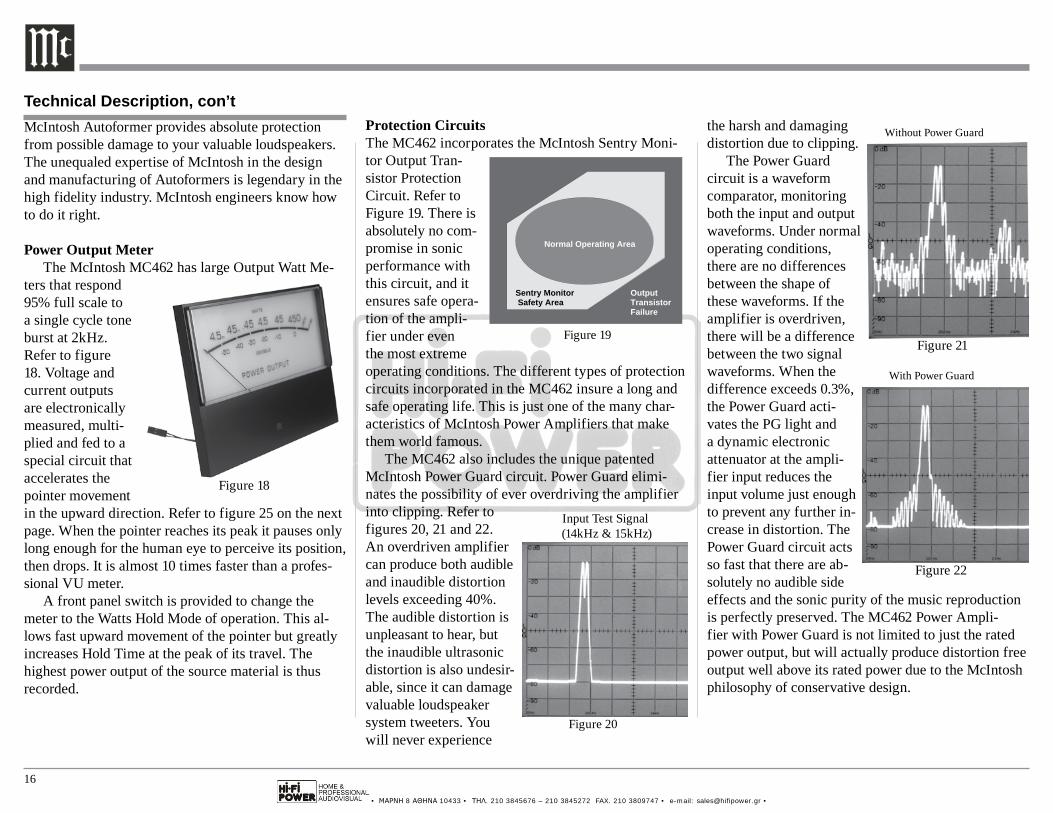
the harsh and damaging distortion due to clipping.
The Power Guard circuit is a waveform comparator, monitoring both the input and output waveforms. Under normal operating conditions, there are no differences between the shape of these waveforms. If the amplifier is overdriven, there will be a difference between the two signal waveforms. When the difference exceeds 0.3%, the Power Guard acti-vates the PG light and a dynamic electronic attenuator at the ampli-fier input reduces the input volume just enough to prevent any further in-crease in distortion. The Power Guard circuit acts so fast that there are ab-solutely no audible side effects and the sonic purity of the music reproduction is perfectly preserved. The MC462 Power Ampli-fier with Power Guard is not limited to just the rated power output, but will actually produce distortion free output well above its rated power due to the McIntosh philosophy of conservative design.
Protection CircuitsThe MC462 incorporates the McIntosh Sentry Moni-tor Output Tran-sistor Protection Circuit. Refer to Figure 19. There is absolutely no com-promise in sonic performance with this circuit, and it ensures safe opera-tion of the ampli-fier under even the most extreme operating conditions. The different types of protection circuits incorporated in the MC462 insure a long and safe operating life. This is just one of the many char-acteristics of McIntosh Power Amplifiers that make them world famous.
The MC462 also includes the unique patented McIntosh Power Guard circuit. Power Guard elimi-nates the possibility of ever overdriving the amplifier into clipping. Refer to figures 20, 21 and 22. An overdriven amplifier can produce both audible and inaudible distortion levels exceeding 40%. The audible distortion is unpleasant to hear, but the inaudible ultrasonic distortion is also undesir-able, since it can damage valuable loudspeaker system tweeters. You will never experience
McIntosh Autoformer provides absolute protection from possible damage to your valuable loudspeakers. The unequaled expertise of McIntosh in the design and manufacturing of Autoformers is legendary in the high fidelity industry. McIntosh engineers know how to do it right.
Power Output MeterThe McIntosh MC462 has large Output Watt Me-
ters that respond 95% full scale to a single cycle tone burst at 2kHz. Refer to figure 18. Voltage and current outputs are electronically measured, multi-plied and fed to a special circuit that accelerates the pointer movement in the upward direction. Refer to figure 25 on the next page. When the pointer reaches its peak it pauses only long enough for the human eye to perceive its position, then drops. It is almost 10 times faster than a profes-sional VU meter.
A front panel switch is provided to change the meter to the Watts Hold Mode of operation. This al-lows fast upward movement of the pointer but greatly increases Hold Time at the peak of its travel. The highest power output of the source material is thus recorded.
Figure 21
Without Power Guard
Figure 20
Input Test Signal (14kHz & 15kHz)
Figure 22
With Power Guard
Figure 19
Normal Operating Area
Sentry Monitor Safety Area
OutputTransistorFailure
Technical Description, con’t
Figure 18
• ΜΑΡΝΗ 8 ΑΘΗΝΑ 10433 • ΤΗΛ. 210 3845676 – 210 3845272 FAX. 210 3809747 • e-mail: [email protected] •
17
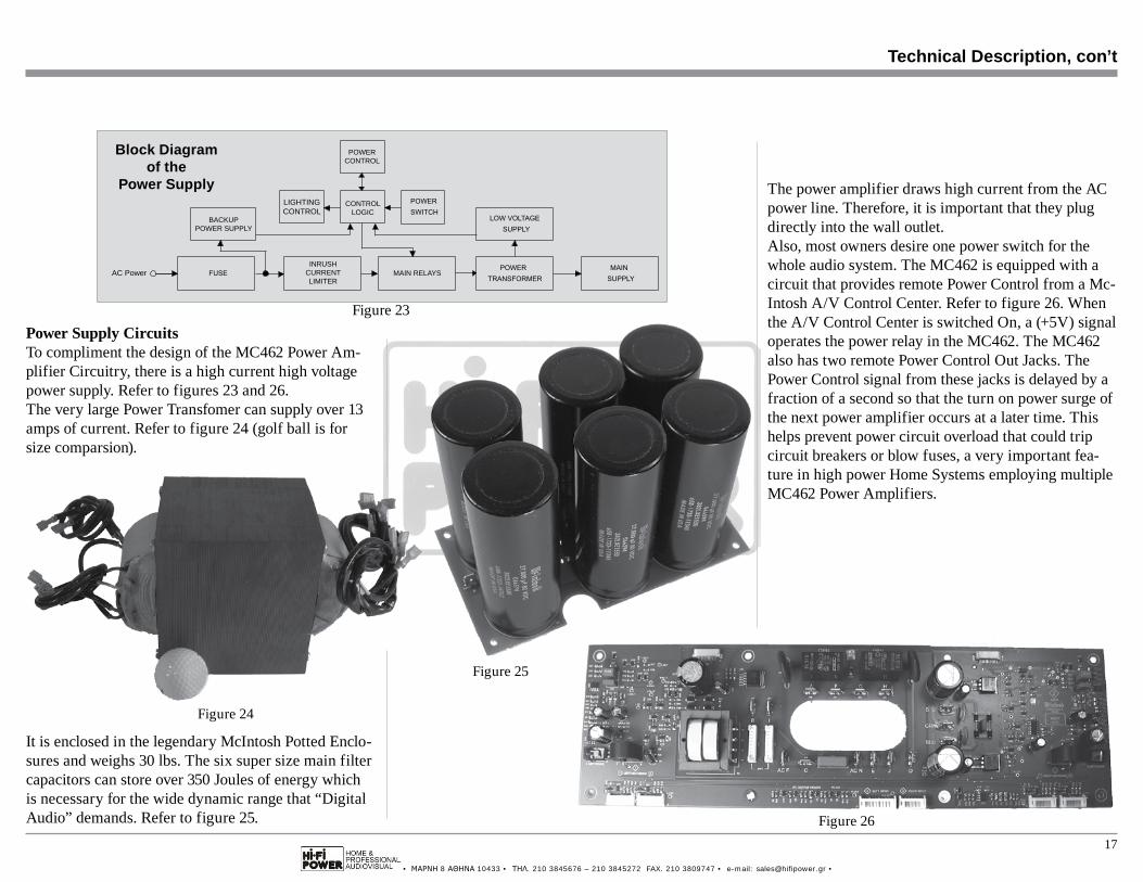
It is enclosed in the legendary McIntosh Potted Enclo-sures and weighs 30 lbs. The six super size main filter capacitors can store over 350 Joules of energy which is necessary for the wide dynamic range that “Digital Audio” demands. Refer to figure 25.
Power Supply CircuitsTo compliment the design of the MC462 Power Am-plifier Circuitry, there is a high current high voltage power supply. Refer to figures 23 and 26.The very large Power Transfomer can supply over 13 amps of current. Refer to figure 24 (golf ball is for size comparsion).
Technical Description, con’t
Figure 23
INRUSHCURRENTLIMITER
AC Power MAIN RELAYS
BACKUPPOWER SUPPLY
CONTROLLOGIC
LIGHTINGCONTROL
POWERCONTROL
Block Diagramof the
Power Supply
Figure 24
Figure 26
Figure 25
The power amplifier draws high current from the AC power line. Therefore, it is important that they plug directly into the wall outlet.Also, most owners desire one power switch for the whole audio system. The MC462 is equipped with a circuit that provides remote Power Control from a Mc-Intosh A/V Control Center. Refer to figure 26. When the A/V Control Center is switched On, a (+5V) signal operates the power relay in the MC462. The MC462 also has two remote Power Control Out Jacks. The Power Control signal from these jacks is delayed by a fraction of a second so that the turn on power surge of the next power amplifier occurs at a later time. This helps prevent power circuit overload that could trip circuit breakers or blow fuses, a very important fea-ture in high power Home Systems employing multiple MC462 Power Amplifiers.

• ΜΑΡΝΗ 8 ΑΘΗΝΑ 10433 • ΤΗΛ. 210 3845676 – 210 3845272 FAX. 210 3809747 • e-mail: [email protected] •
18
Specifications
Specifications
Power OutputMinimum sine wave continuous average power output per channel, with both channels operating is:450 watts into 2 ohm load450 watts into 4 ohm load450 watts into 8 ohm load
Output Load Impedance2, 4 or 8 ohms
Rated Power Band20Hz to 20,000Hz
Total Harmonic Distortion0.005% maximum harmonic distortion at any power level from 250 milliwatts to rated power, 20Hz to 20,000Hz
Dynamic Headroom3.0dB
Frequency Response+0, -0.25dB from 20Hz to 20,000Hz+0, -3.0dB from 10Hz to 100,000Hz
Input Sensitivity (for rated output)4.2 Volts Balanced2.1 Volts Unbalanced
Signal To Noise Ratio (A-Weighted)95dB Balanced (122dB below rated output)93dB Unbalanced (120dB below rated output)
Intermodulation Distortion0.005% maximum, if the instantaneous peak power output does not exceed twice the rated power output for any combination of frequencies from 20Hz to 20,000Hz.
Wide Band Damping FactorGreater than 40
Input Impedance22,000 ohms Balanced22,000 ohms Unbalanced
Voltage Gain29dB, 8 Ohms26dB, 4 Ohms23dB, 2 Ohms
Power GuardLess than 2% Total Harmonic Distortion with up to a 14dB overdrive signal
Power Control Input5-15VDC, less than 1mA
Power Control Output 1 and 212VDC, 50mA maximum totalOutput is delayed 0.2 seconds from turn On
Power RequirementsField AC Voltage conversion of the MC462 is not possible. The MC462 is factory configured for one of the following AC Voltages:100V ~ 50/60Hz at 12 Amps110V ~ 50/60Hz at 11 Amps120V ~ 50/60Hz at 10 Amps127V ~ 50/60Hz at 10 Amps220V ~ 50/60Hz at 6 Amps230V ~ 50/60Hz at 6 Amps240V ~ 50/60Hz at 6 AmpsStandby: less than 0.5 watt
Note: Refer to the rear panel of the MC462 for the cor-rect voltage.
Overall DimensionsWidth is 17-1/2 inches (44.5cm)Height is 9-7/16 inches (24cm) including feetDepth is 22-1/2 inches (57.2cm) including the Front Panel, Handles and Cables
Weight115 pounds (52.3 kg) net, 148 pounds (67.3 kg) in ship-ping carton
Shipping Carton DimensionsWidth is 29-1/2 inches (74.93cm)Depth is 29 inches (73.66cm)Height is 17 inches (43.18cm)
• ΜΑΡΝΗ 8 ΑΘΗΝΑ 10433 • ΤΗΛ. 210 3845676 – 210 3845272 FAX. 210 3809747 • e-mail: [email protected] •
19
Packing Instructions
Packing Instructions
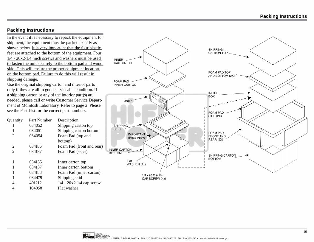
In the event it is necessary to repack the equipment for shipment, the equipment must be packed exactly as shown below. It is very important that the four plastic feet are attached to the bottom of the equipment. Four 1/4 - 20x2-1/4 inch screws and washers must be used to fasten the unit securely to the bottom pad and wood skid. This will ensure the proper equipment location on the bottom pad. Failure to do this will result in shipping damage.Use the original shipping carton and interior parts only if they are all in good serviceable condition. If a shipping carton or any of the interior part(s) are needed, please call or write Customer Service Depart-ment of McIntosh Laboratory. Refer to page 2. Please see the Part List for the correct part numbers.
Quantity Part Number Description 1 034052 Shipping carton top 1 034051 Shipping carton bottom 2 034054 Foam Pad (top and bottom) 2 034186 Foam Pad (front and rear) 2 034187 Foam Pad (sides)
1 034136 Inner carton top 1 034137 Inner carton bottom 1 034188 Foam Pad (inner carton) 1 034479 Shipping skid 4 401212 1/4 - 20x2-1/4 cap screw 4 104058 Flat washer

• ΜΑΡΝΗ 8 ΑΘΗΝΑ 10433 • ΤΗΛ. 210 3845676 – 210 3845272 FAX. 210 3809747 • e-mail: [email protected] •
The continuous improvement of its products is the policy of McIntosh Laboratory Incorporated who reserve the right to improve design without notice.Printed in the U.S.A.
McIntosh Laboratory, Inc.2 Chambers Street
Binghamton, NY 13903www.mcintoshlabs.com
McIntosh Part No. 04187400