Main Road Tunnel (Northbound) Oizumi-Minami Project
8
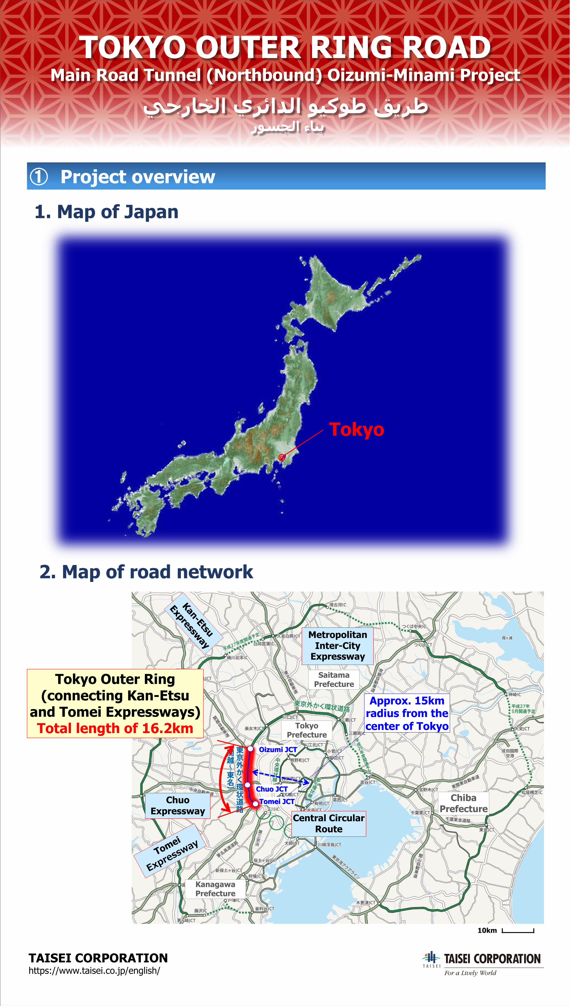
① Project overview 10km Central Circular Route Metropolitan Inter‐City Expressway Kan - Etsu Expressway Chuo Expressway Tomei Expressway Saitama Prefecture Chiba Prefecture Tokyo Prefecture Kanagawa Prefecture Oizumi JCT Chuo JCT Tomei JCT Approx. 15km radius from the center of Tokyo Tokyo TAISEI CORPORATION https://www.taisei.co.jp/english/ TOKYO OUTER RING ROAD Main Road Tunnel (Northbound) Oizumi-Minami Project ط ﺮ ﻳ ﻖ ط ﻮ ﻛ ﯿ ﻮ ا ﻟ ﺪ ا ﺋ ﺮ ي ا ﻟ ﺨ ﺎ ر ﺟ ﻲ ﺑ ﻨ ﺎ ء ا ﻟ ﺠ ﺴ ﻮ رTokyo Outer Ring (connecting Kan-Etsu and Tomei Expressways) Total length of 16.2km 2. Map of road network 1. Map of Japan
Transcript of Main Road Tunnel (Northbound) Oizumi-Minami Project
① Project overview
10km
Central Circular Route
Metropolitan Inter‐City
Expressway
Kan-Etsu
Expressway
Chuo Expressway
Tomei
Expressway
Saitama Prefecture
Chiba Prefecture
Tokyo Prefecture
Kanagawa Prefecture
Oizumi JCT
Chuo JCTTomei JCT
Approx. 15km radius from the center of Tokyo
Tokyo
TAISEI CORPORATION https://www.taisei.co.jp/english/
TOKYO OUTER RING ROADMain Road Tunnel (Northbound) Oizumi-Minami Project
يجراخلا يرئادلا ویكوط قيرطروسجلا ءانب
Tokyo Outer Ring (connecting Kan-Etsu
and Tomei Expressways) Total length of 16.2km
2. Map of road network
1. Map of Japan
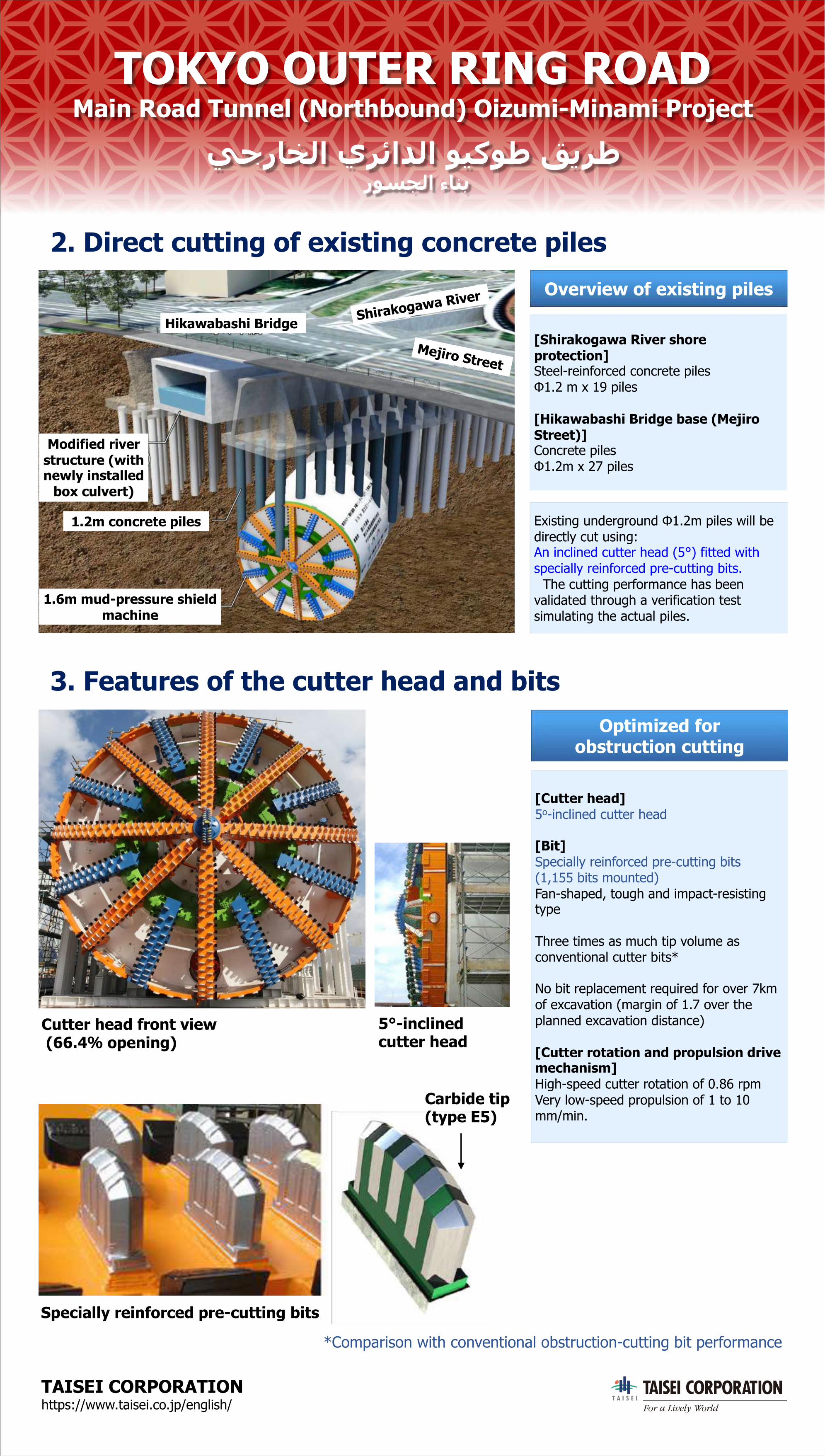
Carbide tip(type E5)
Cutter head front view(66.4% opening)
Specially reinforced pre-cutting bits
5°-inclinedcutter head
*Comparison with conventional obstruction-cutting bit performance
Existing underground Φ1.2m piles will be directly cut using:An inclined cutter head (5°) fitted with specially reinforced pre-cutting bits.
The cutting performance has been validated through a verification test simulating the actual piles.
[Shirakogawa River shore protection]Steel-reinforced concrete pilesΦ1.2 m x 19 piles
[Hikawabashi Bridge base (Mejiro Street)]Concrete pilesΦ1.2m x 27 piles
Overview of existing piles
TAISEI CORPORATION https://www.taisei.co.jp/english/
TOKYO OUTER RING ROADMain Road Tunnel (Northbound) Oizumi-Minami Project
يجراخلا يرئادلا ویكوط قيرطروسجلا ءانب
2. Direct cutting of existing concrete piles
3. Features of the cutter head and bits
[Cutter head]5o-inclined cutter head
[Bit]Specially reinforced pre-cutting bits(1,155 bits mounted)Fan-shaped, tough and impact-resisting type
Three times as much tip volume as conventional cutter bits*
No bit replacement required for over 7kmof excavation (margin of 1.7 over the planned excavation distance)
[Cutter rotation and propulsion drive mechanism]High-speed cutter rotation of 0.86 rpmVery low-speed propulsion of 1 to 10 mm/min.
Optimized for obstruction cutting
Hikawabashi Bridge Shirakogawa River
Mejiro Street
Modified river structure (with newly installed
box culvert)
1.2m concrete piles
1.6m mud-pressure shield machine
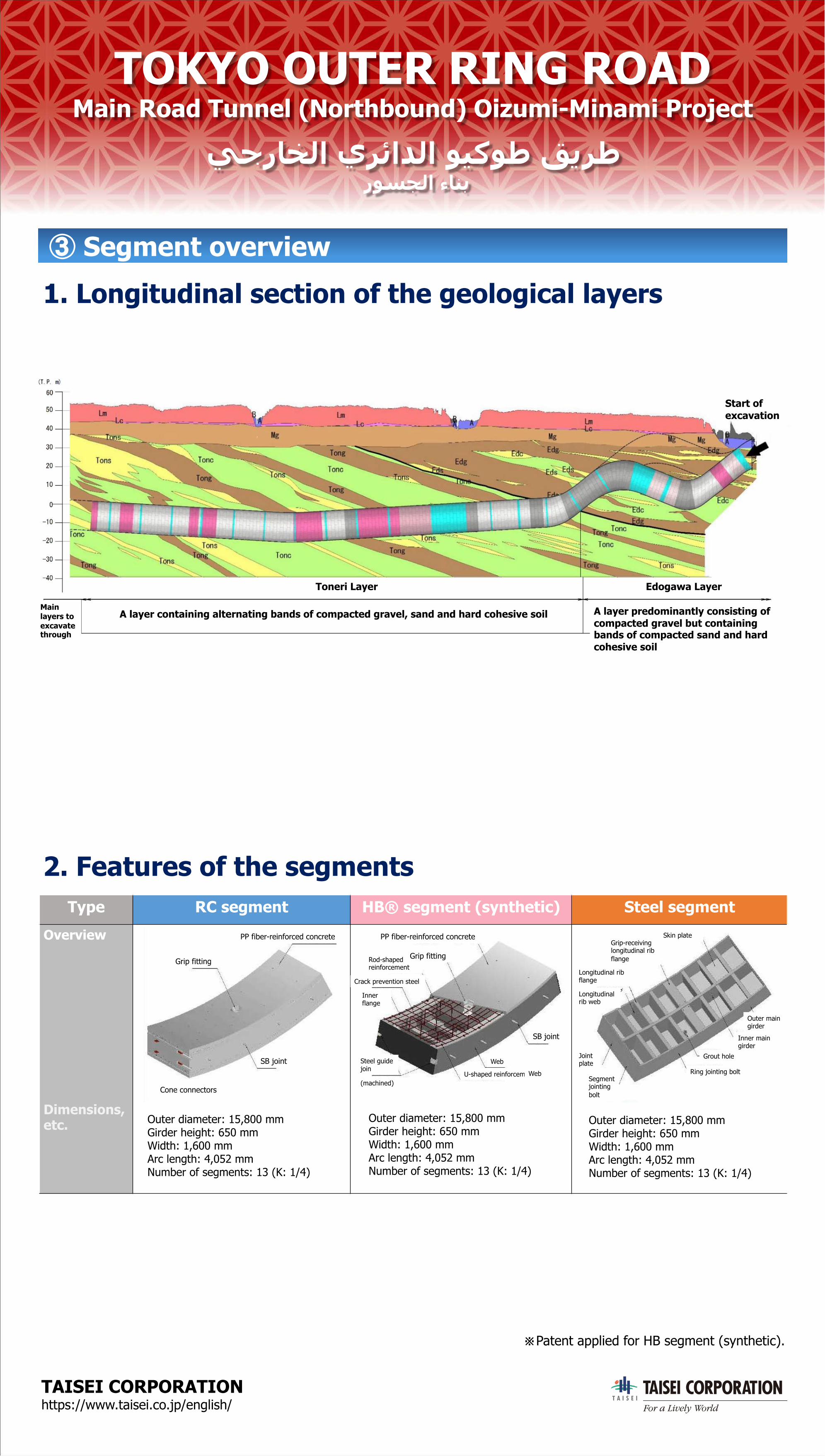
Type RC segment HB® segment (synthetic) Steel segmentOverview
Dimensions, etc.
2. Features of the segments
TAISEI CORPORATION https://www.taisei.co.jp/english/
TOKYO OUTER RING ROADMain Road Tunnel (Northbound) Oizumi-Minami Project
يجراخلا يرئادلا ویكوط قيرطروسجلا ءانب
③ Segment overview1. Longitudinal section of the geological layers
※Patent applied for HB segment (synthetic).
※
Outer diameter: 15,800 mmGirder height: 650 mmWidth: 1,600 mmArc length: 4,052 mmNumber of segments: 13 (K: 1/4)
Outer diameter: 15,800 mmGirder height: 650 mmWidth: 1,600 mmArc length: 4,052 mmNumber of segments: 13 (K: 1/4)
Outer diameter: 15,800 mmGirder height: 650 mmWidth: 1,600 mmArc length: 4,052 mmNumber of segments: 13 (K: 1/4)
PP fiber-reinforced concrete
Grip fitting
SB joint
Cone connectors
Rod-shaped reinforcement
Crack prevention steel
Inner flange
Steel guide join
(machined)U-shaped reinforcement block
Web
Web
Skin plateGrip-receiving longitudinal rib flange
Longitudinal rib flange
Longitudinal rib web
Joint plate
Segment jointing bolt
Grout hole
Ring jointing bolt
PP fiber-reinforced concrete
Grip fitting
SB joint
Outer main girder
Inner main girder
Toneri Layer Edogawa Layer
A layer containing alternating bands of compacted gravel, sand and hard cohesive soil A layer predominantly consisting of compacted gravel but containing bands of compacted sand and hard cohesive soil
Main layers to excavate through
Start of excavation
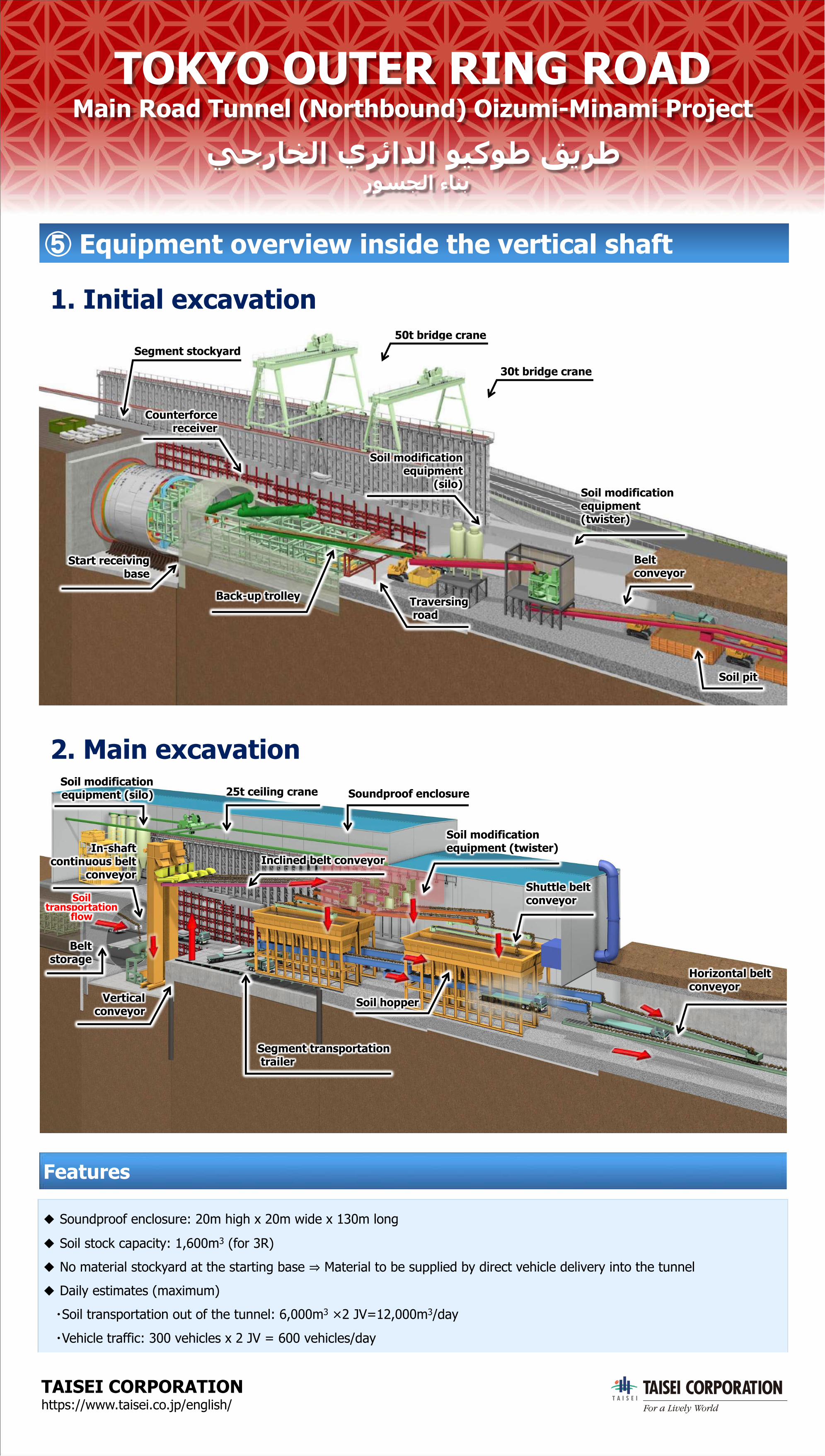
In-shaft continuous belt
conveyor
Belt storage
Vertical conveyor
Inclined belt conveyor
Soil modification equipment (twister)
Shuttle belt conveyor
Soil hopper
Horizontal belt conveyor
Segment transportationtrailer
Soil transportation
flow
25t ceiling crane Soundproof enclosureSoil modification equipment (silo)
50t bridge crane
Counterforcereceiver
Segment stockyard
Start receiving base
Back-up trolley Traversingroad
Soil modification equipment
(silo)Soil modification equipment(twister)
Belt conveyor
30t bridge crane
Soil pit
TAISEI CORPORATION https://www.taisei.co.jp/english/
TOKYO OUTER RING ROADMain Road Tunnel (Northbound) Oizumi-Minami Project
يجراخلا يرئادلا ویكوط قيرطروسجلا ءانب
⑤ Equipment overview inside the vertical shaft
1. Initial excavation
2. Main excavation
◆ Soundproof enclosure: 20m high x 20m wide x 130m long
◆ Soil stock capacity: 1,600m3 (for 3R)◆ No material stockyard at the starting base ⇒ Material to be supplied by direct vehicle delivery into the tunnel◆ Daily estimates (maximum)・Soil transportation out of the tunnel: 6,000m3 ×2 JV=12,000m3/day・Vehicle traffic: 300 vehicles x 2 JV = 600 vehicles/day
Features
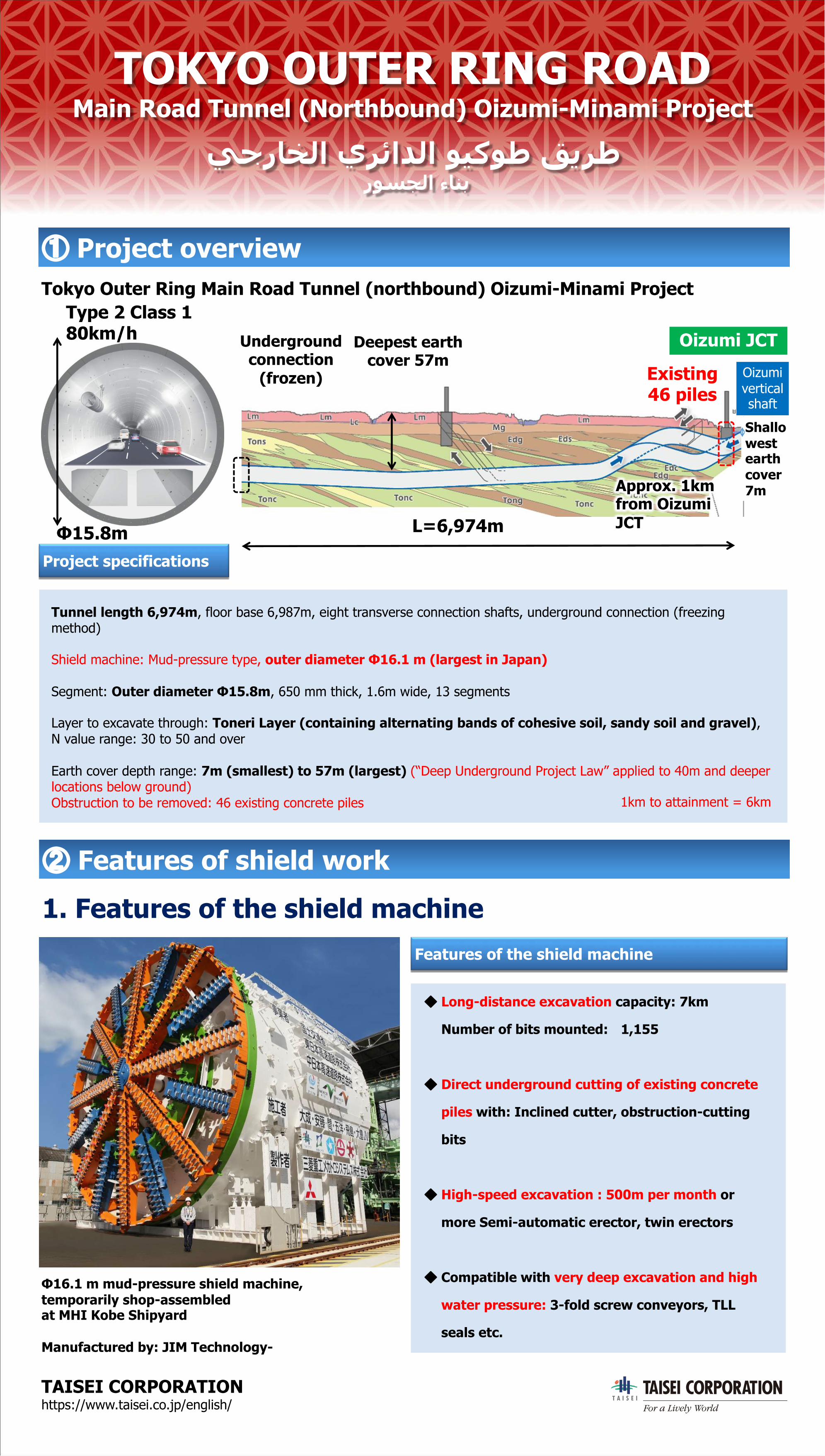
Tunnel length 6,974m, floor base 6,987m, eight transverse connection shafts, underground connection (freezing method)
Shield machine: Mud-pressure type, outer diameter Φ16.1 m (largest in Japan)
Segment: Outer diameter Φ15.8m, 650 mm thick, 1.6m wide, 13 segments
Layer to excavate through: Toneri Layer (containing alternating bands of cohesive soil, sandy soil and gravel),N value range: 30 to 50 and over
Earth cover depth range: 7m (smallest) to 57m (largest) (“Deep Underground Project Law” applied to 40m and deeper locations below ground)Obstruction to be removed: 46 existing concrete piles
L=6,974m
Deepest earth cover 57m
Shallowest earth cover7m
Existing 46 piles
Underground connection
(frozen)
Approx. 1km from OizumiJCT
Type 2 Class 1 80km/h
Φ15.8m
Oizumi JCTOizumivertical shaft
Tokyo Outer Ring Main Road Tunnel (northbound) Oizumi-Minami Project
Φ16.1 m mud-pressure shield machine,temporarily shop-assembled at MHI Kobe Shipyard
Manufactured by: JIM Technology-
1km to attainment = 6km
TAISEI CORPORATION https://www.taisei.co.jp/english/
TOKYO OUTER RING ROADMain Road Tunnel (Northbound) Oizumi-Minami Project
يجراخلا يرئادلا ویكوط قيرطروسجلا ءانب
① Project overview
Project specifications
② Features of shield work
1. Features of the shield machineFeatures of the shield machine
◆ Long-distance excavation capacity: 7km
Number of bits mounted: 1,155
◆ Direct underground cutting of existing concrete
piles with: Inclined cutter, obstruction-cutting
bits
◆ High-speed excavation : 500m per month or
more Semi-automatic erector, twin erectors
◆ Compatible with very deep excavation and high
water pressure: 3-fold screw conveyors, TLL
seals etc.
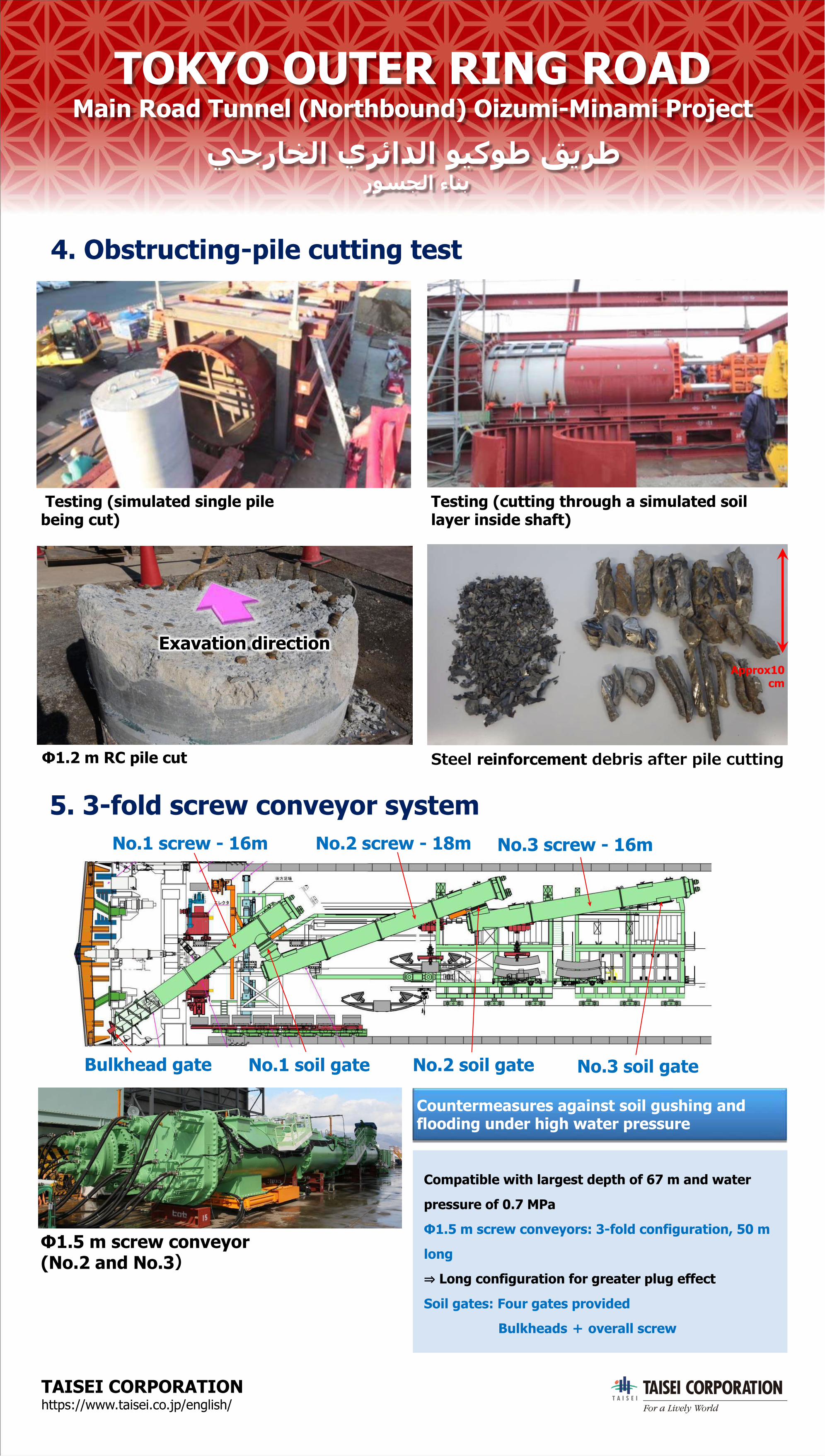
Φ1.5 m screw conveyor (No.2 and No.3)
No.1 screw - 16m No.2 screw - 18m No.3 screw - 16m
No.1 soil gate No.2 soil gate No.3 soil gateBulkhead gate
Exavation direction
Testing (simulated single pile being cut)
Testing (cutting through a simulated soil layer inside shaft)
Φ1.2 m RC pile cut Steel reinforcement debris after pile cutting
Approx10 cm
TAISEI CORPORATION https://www.taisei.co.jp/english/
TOKYO OUTER RING ROADMain Road Tunnel (Northbound) Oizumi-Minami Project
يجراخلا يرئادلا ویكوط قيرطروسجلا ءانب
4. Obstructing-pile cutting test
5. 3-fold screw conveyor system
Countermeasures against soil gushing and flooding under high water pressure
Compatible with largest depth of 67 m and water
pressure of 0.7 MPa
Φ1.5 m screw conveyors: 3-fold configuration, 50 m
long
⇒ Long configuration for greater plug effect
Soil gates: Four gates provided
Bulkheads + overall screw
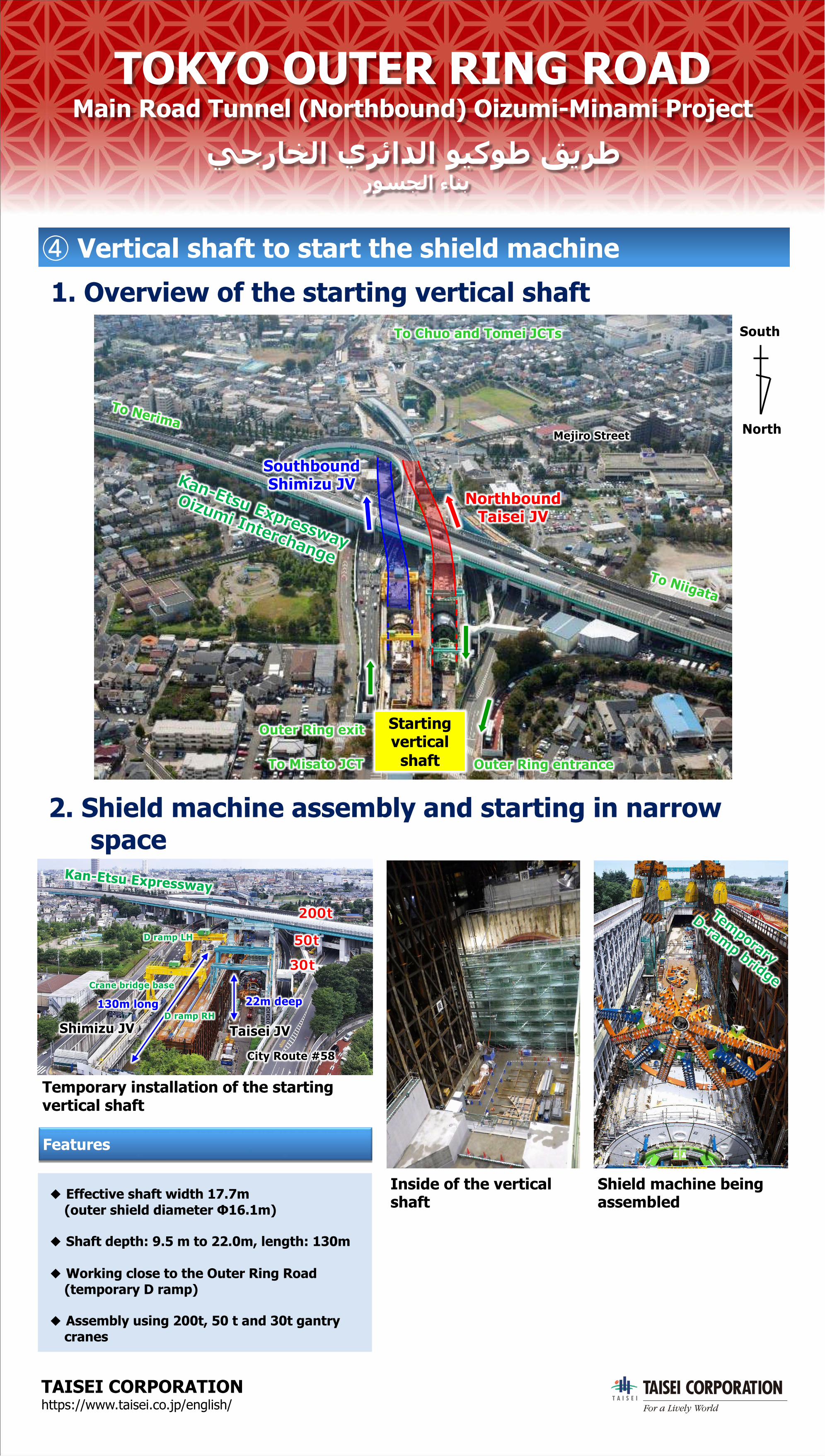
50t
30t
200t
22m deep130m long
Taisei JV
City Route #58
Kan-Etsu Expressway
D ramp LH
Crane bridge base
Shimizu JVD ramp RH
Shield machine being assembled
Inside of the vertical shaft
Temporary
D-ramp bridge
Starting vertical
shaft
Mejiro Street
Kan-Etsu Expressway
Oizumi Interchange
Outer Ring exit
To Misato JCT Outer Ring entrance
SouthboundShimizu JV
NorthboundTaisei JV
To Chuo and Tomei JCTs
North
South
To Nerima
To Niigata
TAISEI CORPORATION https://www.taisei.co.jp/english/
TOKYO OUTER RING ROADMain Road Tunnel (Northbound) Oizumi-Minami Project
يجراخلا يرئادلا ویكوط قيرطروسجلا ءانب
1. Overview of the starting vertical shaft④ Vertical shaft to start the shield machine
2. Shield machine assembly and starting in narrow space
Features
Temporary installation of the starting vertical shaft
◆ Effective shaft width 17.7m (outer shield diameter Φ16.1m)
◆ Shaft depth: 9.5 m to 22.0m, length: 130m
◆ Working close to the Outer Ring Road (temporary D ramp)
◆ Assembly using 200t, 50 t and 30t gantry cranes
TAISEI CORPORATION https://www.taisei.co.jp/english/
TOKYO OUTER RING ROADMain Road Tunnel (Northbound) Oizumi-Minami Project
يجراخلا يرئادلا ویكوط قيرطروسجلا ءانب
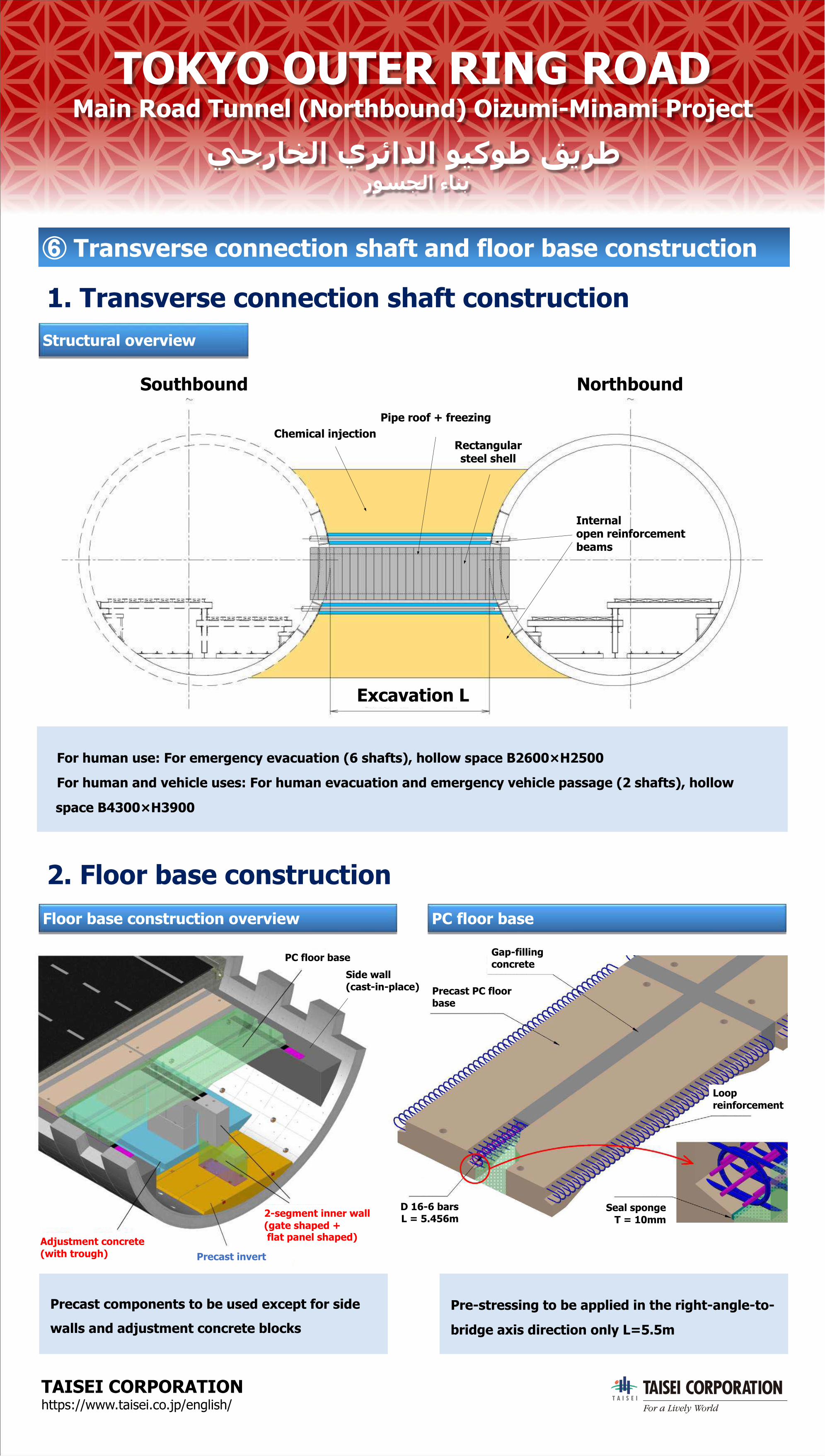
⑥ Transverse connection shaft and floor base construction
1. Transverse connection shaft construction
Floor base construction overview
2. Floor base constructionPC floor base
PC floor base
Adjustment concrete (with trough) Precast invert
Gap-filling concrete
Precast PC floor base
Loop reinforcement
D 16-6 barsL = 5.456m
Seal spongeT = 10mm
Pipe roof + freezingChemical injection
Internal open reinforcement beams
Rectangular steel shell
Southbound Northbound
Excavation L
Structural overview
Precast components to be used except for side
walls and adjustment concrete blocksPre-stressing to be applied in the right-angle-to-
bridge axis direction only L=5.5m
For human use: For emergency evacuation (6 shafts), hollow space B2600×H2500
For human and vehicle uses: For human evacuation and emergency vehicle passage (2 shafts), hollow
space B4300×H3900
Side wall (cast-in-place)
2-segment inner wall(gate shaped +flat panel shaped)


![Sengiergi Serafeim Tikozoglou [Main]](https://static.fdocument.org/doc/165x107/5477673a5806b5e7738b456f/sengiergi-serafeim-tikozoglou-main.jpg)