Magnetic/Electric Fields for KEK-RCNP EDM Experiment K. Matsuta(Osaka), Y. Masuda(KEK), Y....
35
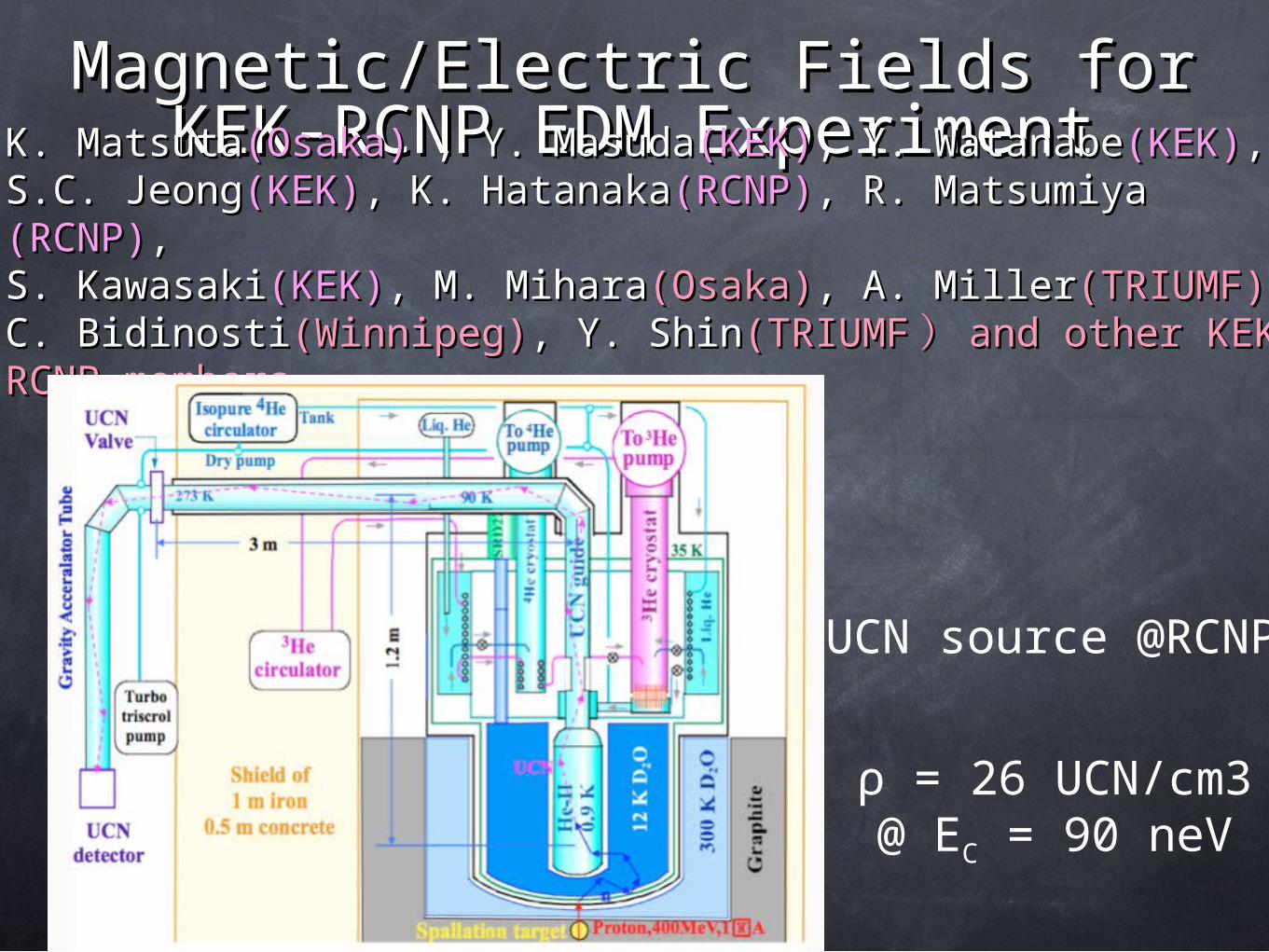
Magnetic/Electric Fields for Magnetic/Electric Fields for KEK-RCNP EDM Experiment KEK-RCNP EDM Experiment K. Matsuta K. Matsuta (Osaka) (Osaka) , Y. Masuda , Y. Masuda (KEK) (KEK) , Y. Watanabe , Y. Watanabe (KEK) (KEK) , , S.C. Jeong S.C. Jeong (KEK) (KEK) , K. Hatanaka , K. Hatanaka (RCNP) (RCNP) , R. Matsumiya , R. Matsumiya (RCNP) (RCNP) , , S. Kawasaki S. Kawasaki (KEK) (KEK) , M. Mihara , M. Mihara (Osaka) (Osaka) , A. Miller , A. Miller (TRIUMF) (TRIUMF) , , C. Bidinosti C. Bidinosti (Winnipeg) (Winnipeg) , Y. Shin , Y. Shin (TRIUMF (TRIUMF ) ) and other KEK and other KEK RCNP members RCNP members UCN source @RCNP ρ = 26 UCN/cm3 @ E C = 90 neV
-
Upload
coral-flowers -
Category
Documents
-
view
228 -
download
2
Transcript of Magnetic/Electric Fields for KEK-RCNP EDM Experiment K. Matsuta(Osaka), Y. Masuda(KEK), Y....
Magnetic/Electric Fields for KEK-Magnetic/Electric Fields for KEK-RCNP EDM ExperimentRCNP EDM Experiment
K. MatsutaK. Matsuta(Osaka)(Osaka) , Y. Masuda , Y. Masuda(KEK)(KEK), Y. Watanabe, Y. Watanabe(KEK)(KEK), , S.C. JeongS.C. Jeong(KEK)(KEK), K. Hatanaka, K. Hatanaka(RCNP)(RCNP), R. Matsumiya , R. Matsumiya (RCNP)(RCNP), , S. KawasakiS. Kawasaki(KEK)(KEK), M. Mihara, M. Mihara(Osaka)(Osaka), A. Miller, A. Miller(TRIUMF)(TRIUMF), , C. BidinostiC. Bidinosti(Winnipeg)(Winnipeg), Y. Shin, Y. Shin(TRIUMF(TRIUMF )) and other KEK-RCNP and other KEK-RCNP membersmembers
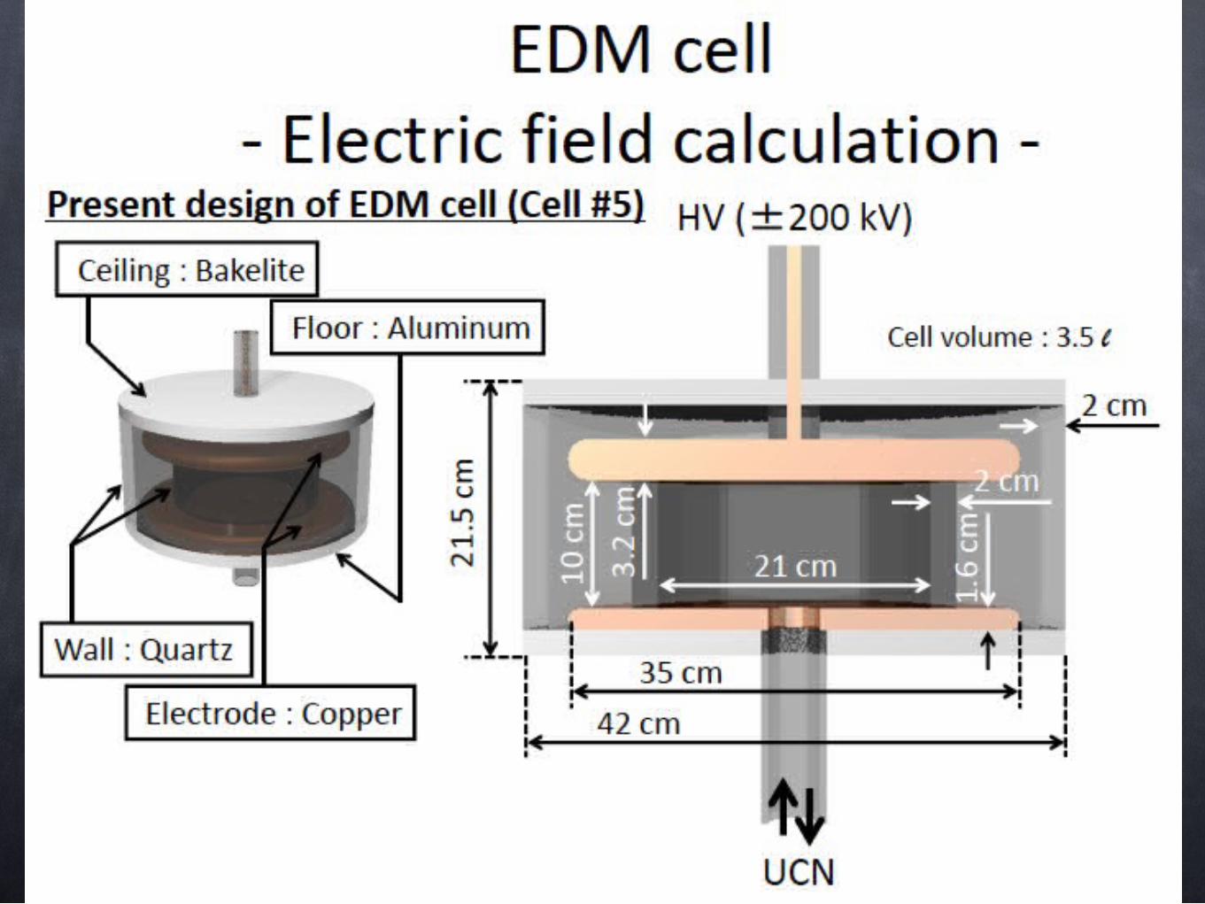
UCN source @RCNP
ρ = 26 UCN/cm3@ EC = 90 neV
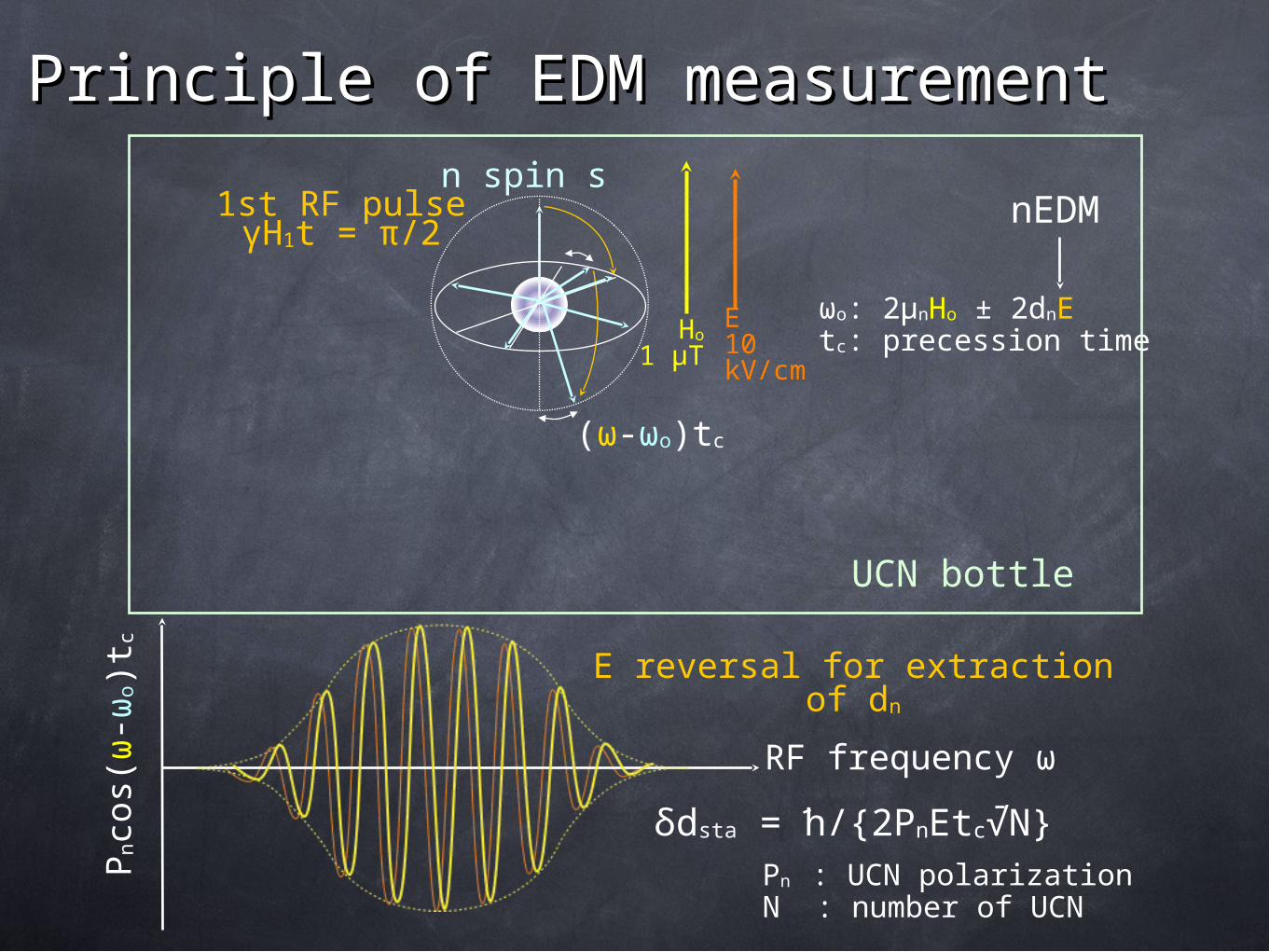
E10 kV/cm
Ho
1 μT
n spin s1st RF pulseγH1t = π/2
Principle of EDM measurementPrinciple of EDM measurement
(ω-ωo)tc
E reversal for extraction of dn
RF frequency ω
Pnco
s(ω
-ωo)t
c
UCN bottle
ωo: 2μnHo ± 2dnE tc: precession time
δdsta = h/{2PnEtc√N}Pn : UCN polarizationN : number of UCN
nEDM
E10 kV/cm
Ho
1 μT
n spin s1st RF pulseγH1t = π/2
Principle of EDM measurementPrinciple of EDM measurement
(ω-ωo)tc
E reversal for extraction of dn
RF frequency ω
Pnco
s(ω
-ωo)t
c
UCN bottle
ωo: 2μnHo ± 2dnE tc: precession time
δdsta = h/{2PnEtc√N}Pn : UCN polarizationN : number of UCN
nEDM
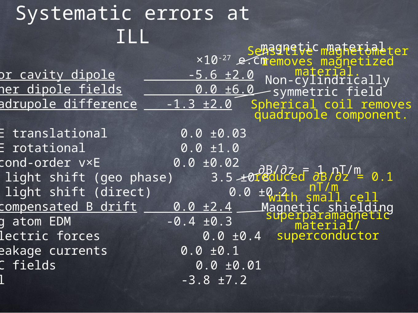
Systematic errors at ILL
×10-27 e.cm1 Door cavity dipole -5.6 ±2.02 Other dipole fields 0.0 ±6.03 Quadrupole difference -1.3 ±2.0
4 v×E translational 0.0 ±0.035 v×E rotational 0.0 ±1.06 Second-order v×E 0.0 ±0.027 Hg light shift (geo phase) 3.5 ±0.88 Hg light shift (direct) 0.0 ±0.29 Uncompensated B drift 0.0 ±2.410 Hg atom EDM -0.4 ±0.311 Electric forces 0.0 ±0.412 Leakage currents 0.0 ±0.113 AC fields 0.0 ±0.01Total -3.8 ±7.2
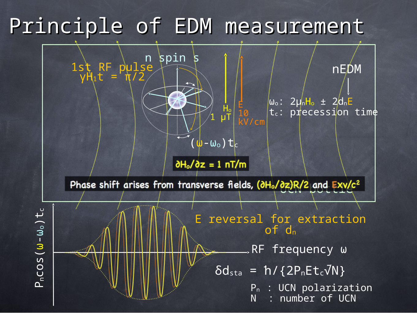
Sensitive magnetometer removes magnetized
material.
superparamagnetic material/
superconductor
Spherical coil removesquadrupole component.
reduced ∂B/∂z = 0.1 nT/mwith small cell
Magnetic shielding
Non-cylindricallysymmetric field
magnetic material
∂B/∂z = 1 nT/m
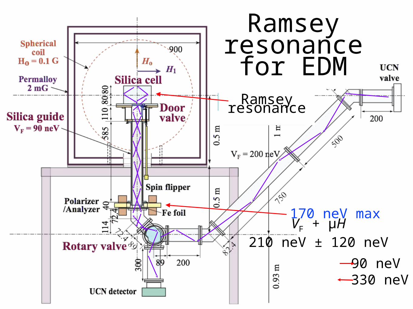
Ramsey resonance for EDM
UCN fillingUCN detectionRamsey
resonance
VF + μH210 neV ± 120 neV
90 neV 330 neV
170 neV max
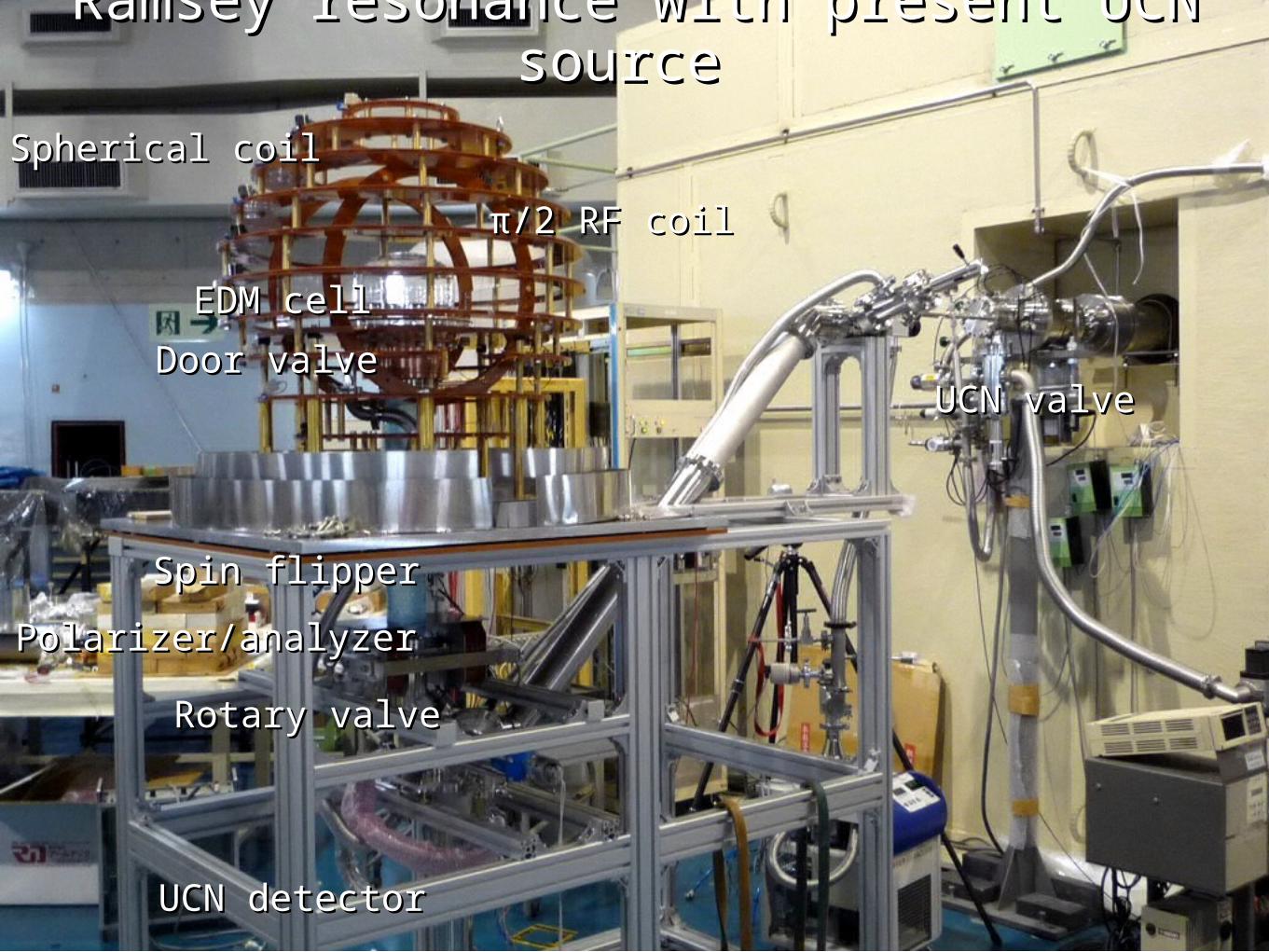
Ramsey resonance with present UCN Ramsey resonance with present UCN source source
π/2 RF coilπ/2 RF coil
Spherical coilSpherical coil
Rotary valveRotary valve
Polarizer/analyzerPolarizer/analyzer
Spin flipperSpin flipper
UCN detectorUCN detector
UCN valveUCN valveDoor valveDoor valve
EDM cellEDM cell
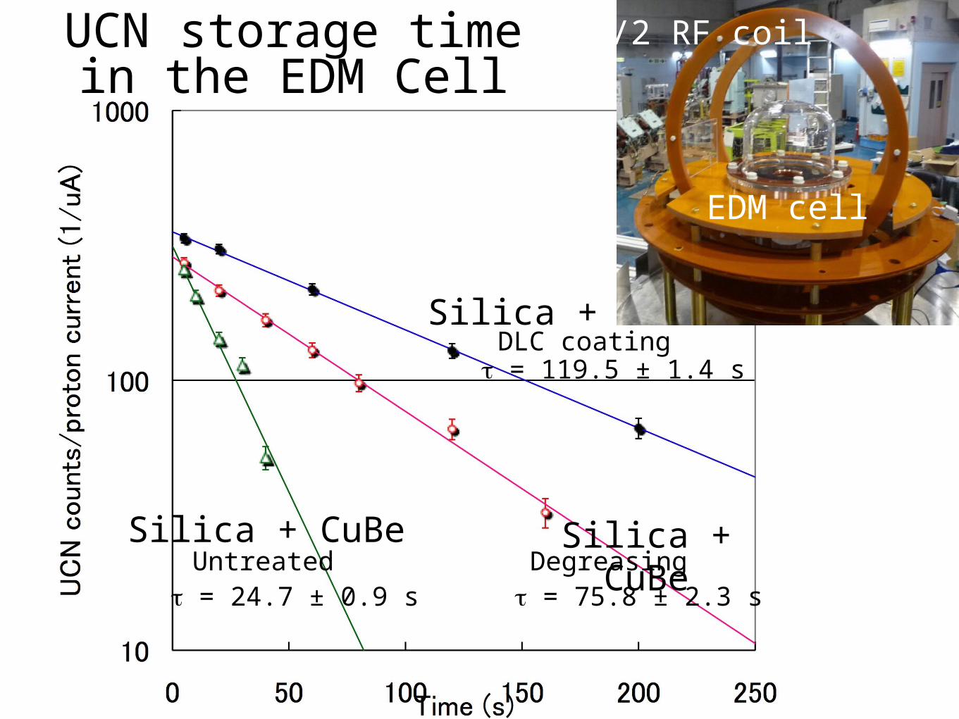
DLC coating
DegreasingUntreated
τ = 119.5 ± 1.4 s
τ = 75.8 ± 2.3 sτ = 24.7 ± 0.9 s
Silica +
Silica + CuBe Silica + CuBe
π/2 RF coil
EDM cell
UCN storage timein the EDM Cell
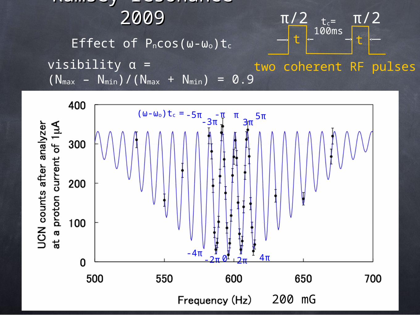
Ramsey resonance Ramsey resonance 20092009
(ω-ωo)tc =
-4π-2π 0 2π 4π
-5π-3π
-π π3π
5π
two coherent RF pulses
t t
tc=100ms
200 mG
Effect of Pncos(ω-ωo)tc
visibility α = (Nmax – Nmin)/(Nmax + Nmin) = 0.9
π/2 π/2
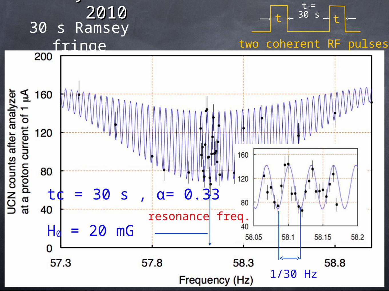
Ramsey resonance Ramsey resonance 20102010
30 s Ramsey fringe two coherent RF pulses
t ttc=30 s
tc = 30 s , α= 0.33
H0 = 20 mG
1/30 Hz
resonance freq.
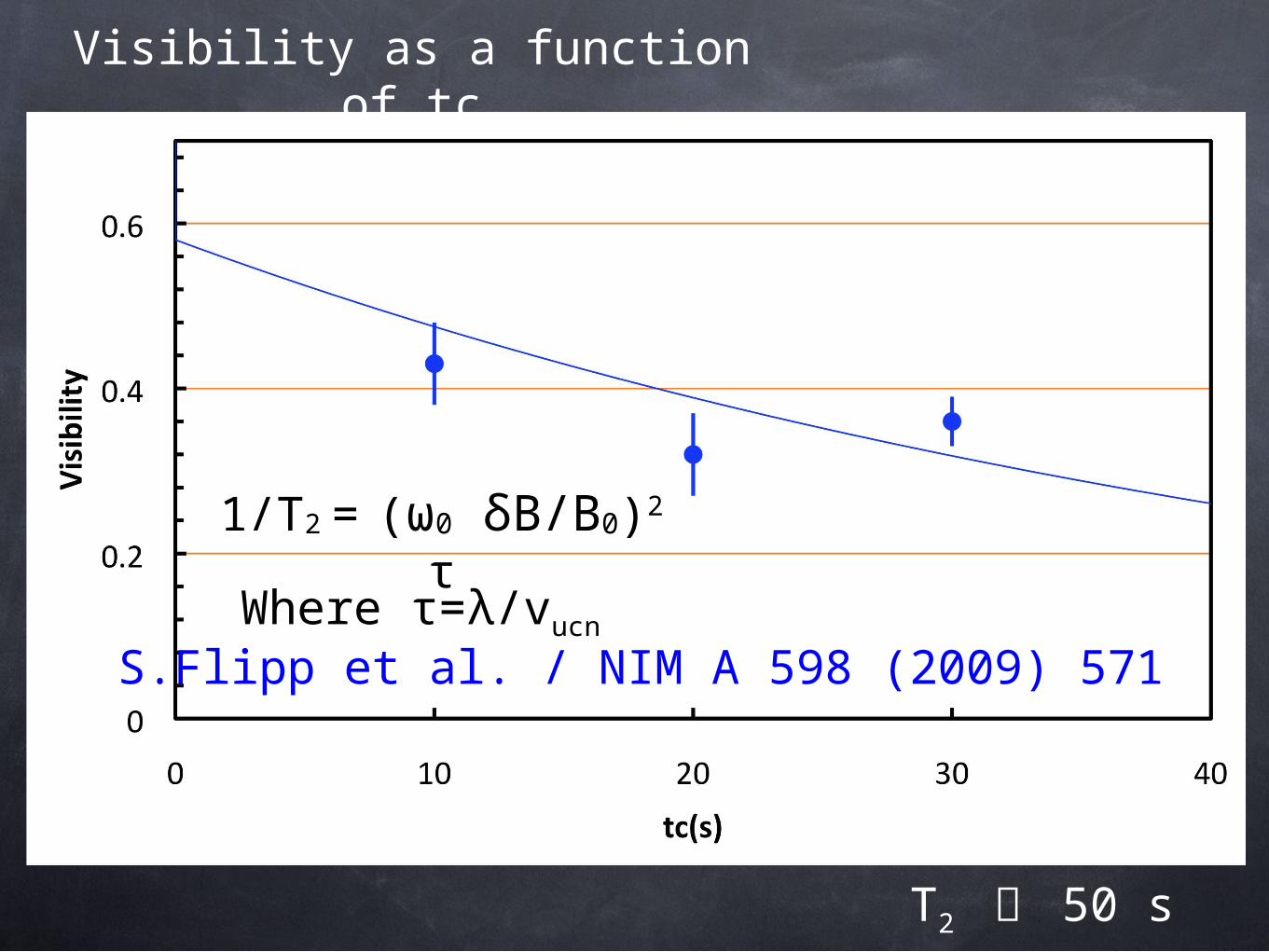
Visibility as a function of tc
T2 〜 50 s
1/T2 = (ω0 δB/B0)2
τ
S.Flipp et al. / NIM A 598 (2009) 571Where τ=λ/vucn
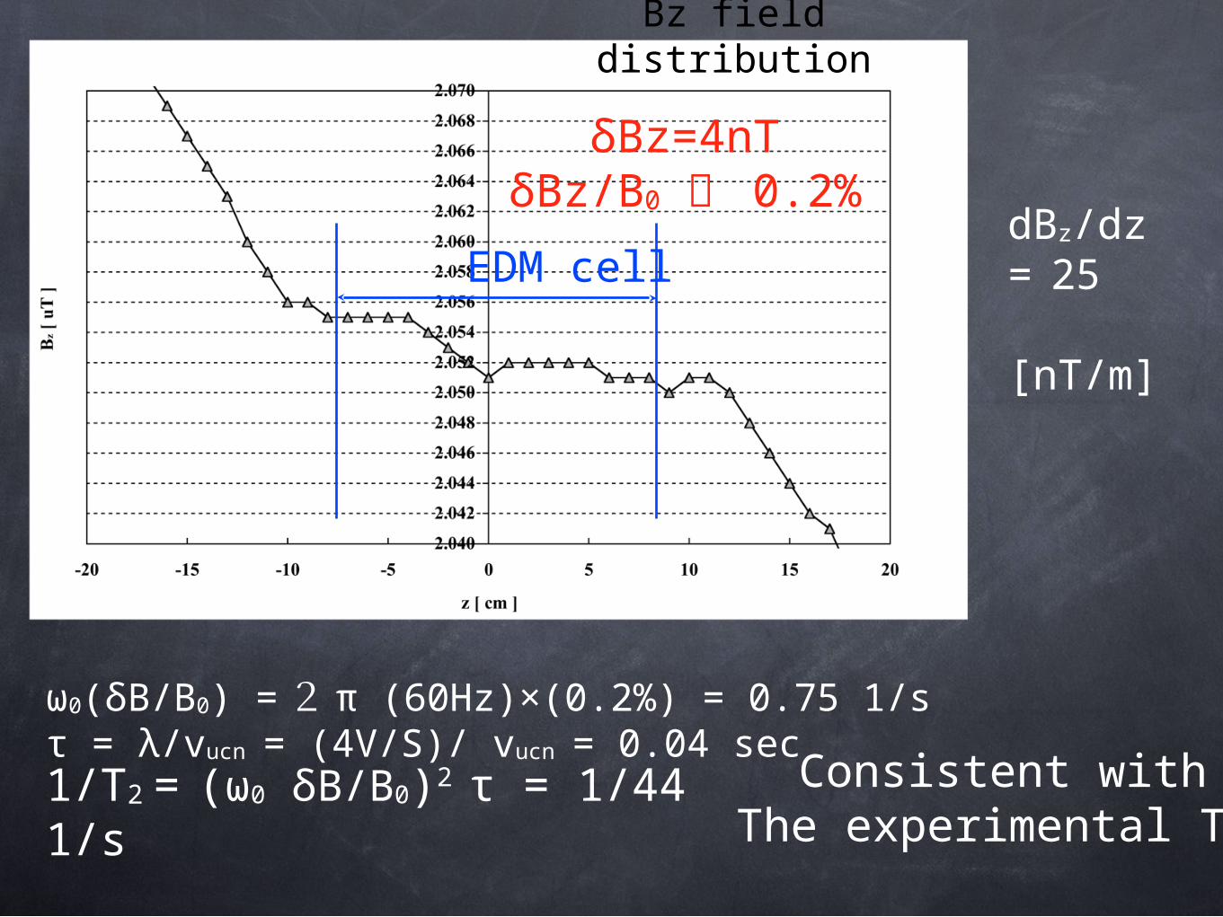
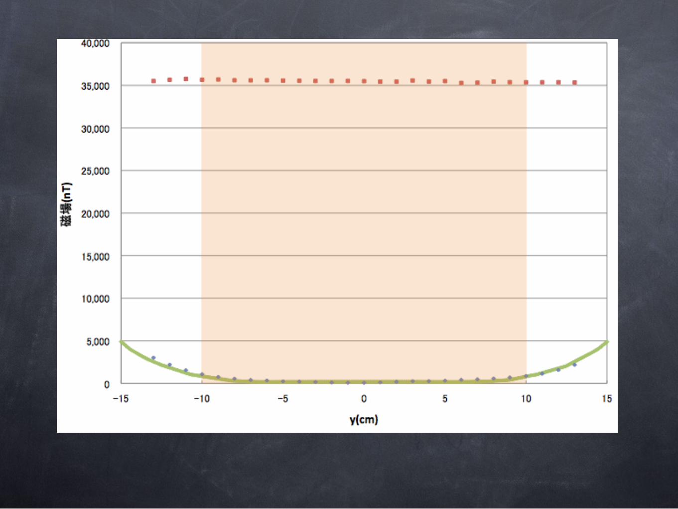
Bz field distribution
EDM cell
δBz=4nTδBz/B0 〜 0.2%
1/T2 = (ω0 δB/B0)2 τ = 1/44 1/s
ω0(δB/B0) = 2 π (60Hz)×(0.2%) = 0.75 1/sτ = λ/vucn = (4V/S)/ vucn = 0.04 sec
dBz/dz= 25 [nT/m]
Consistent withThe experimental T2
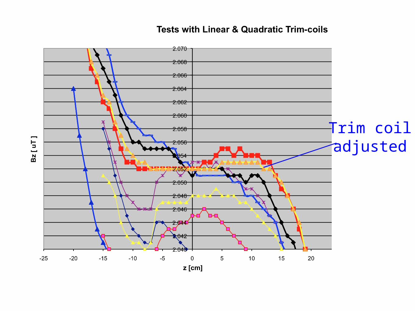
Trim coiladjusted
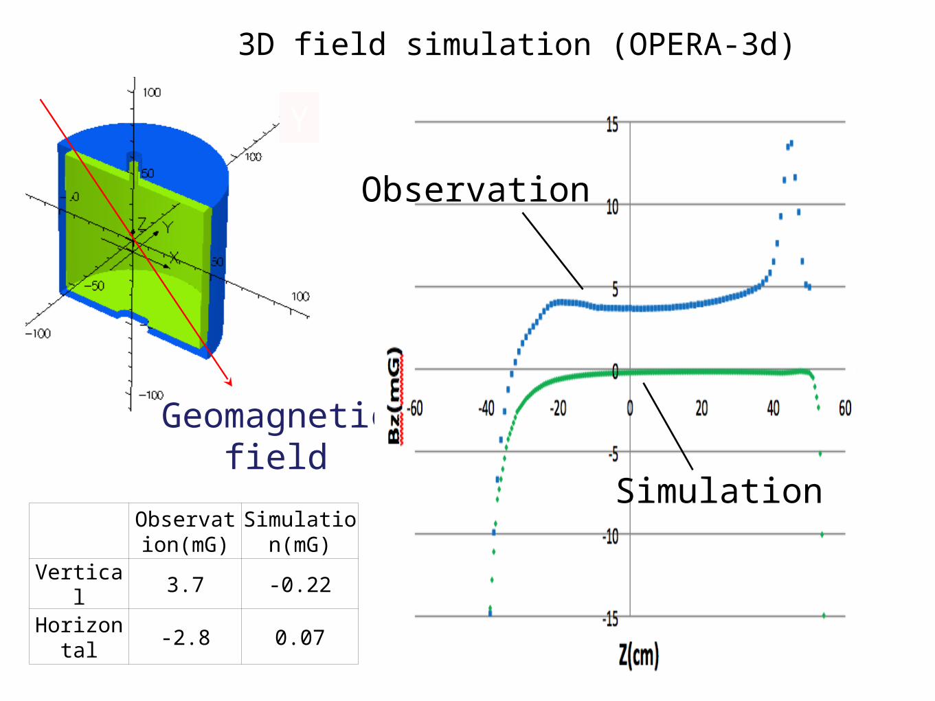
Z
X
Y
Geomagnetic field
3D field simulation (OPERA-3d)
Observation(mG)
Simulation(mG)
Vertical 3.7 -0.22
Horizontal
-2.8 0.07
Observation
Simulation
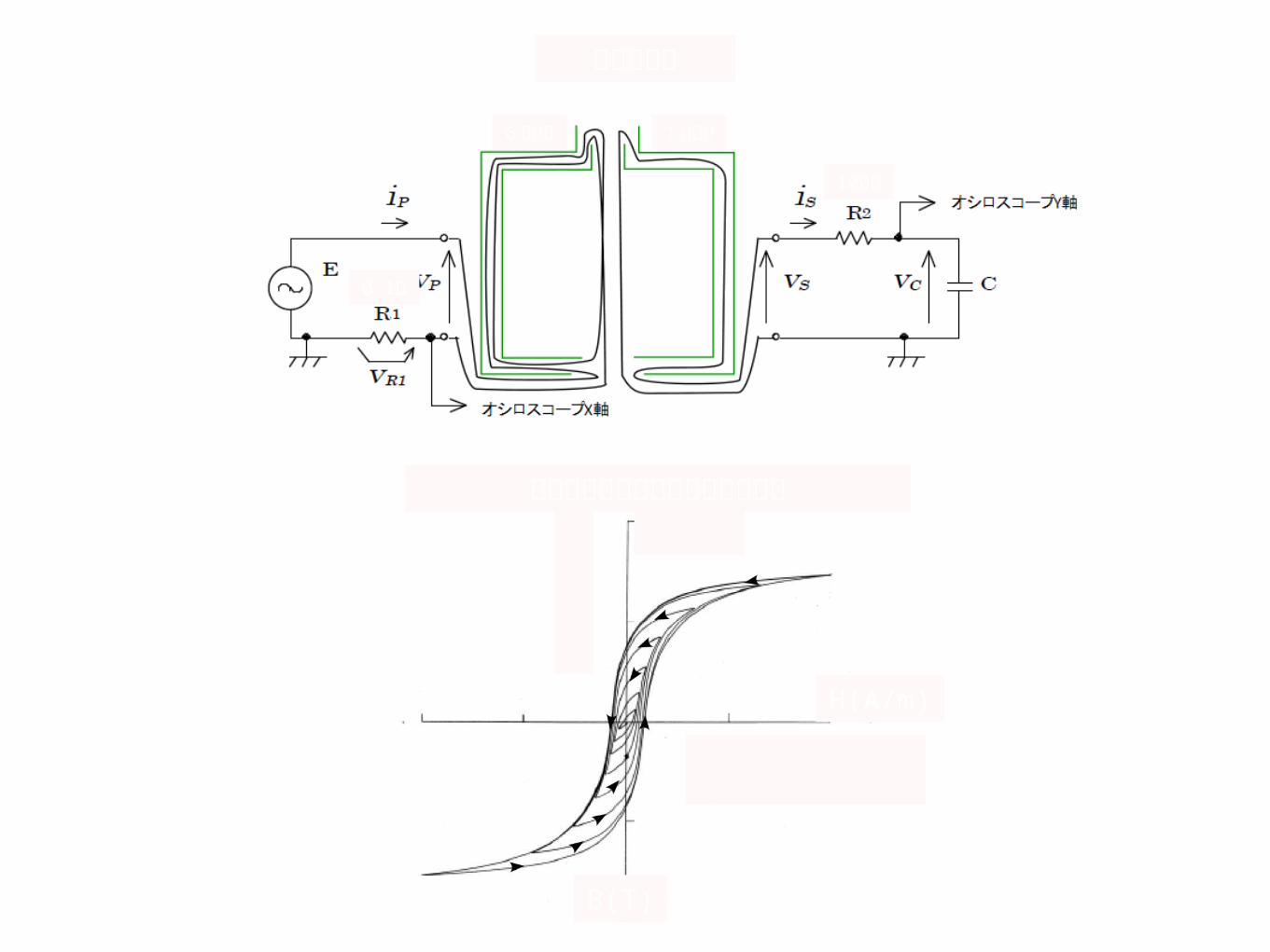
1μF
100Ω
0.1Ω
6 回巻き 1 回巻き
B(T)
H(A/m)
消磁のヒステリシスループの軌跡
消磁回路図
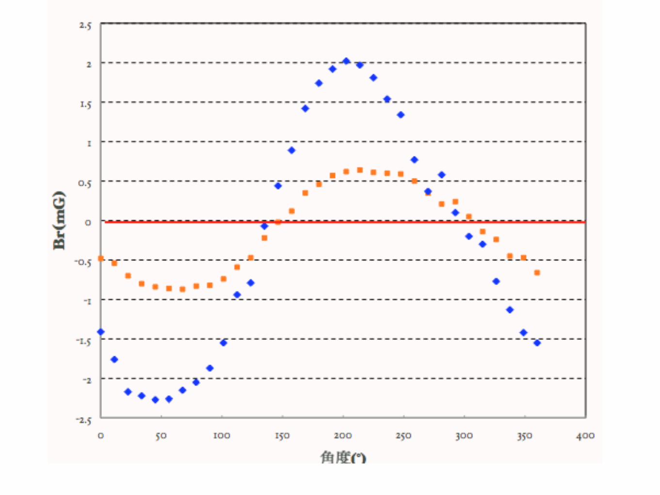
消磁前後で比較 (Br)
消磁前後で比較 (Br)
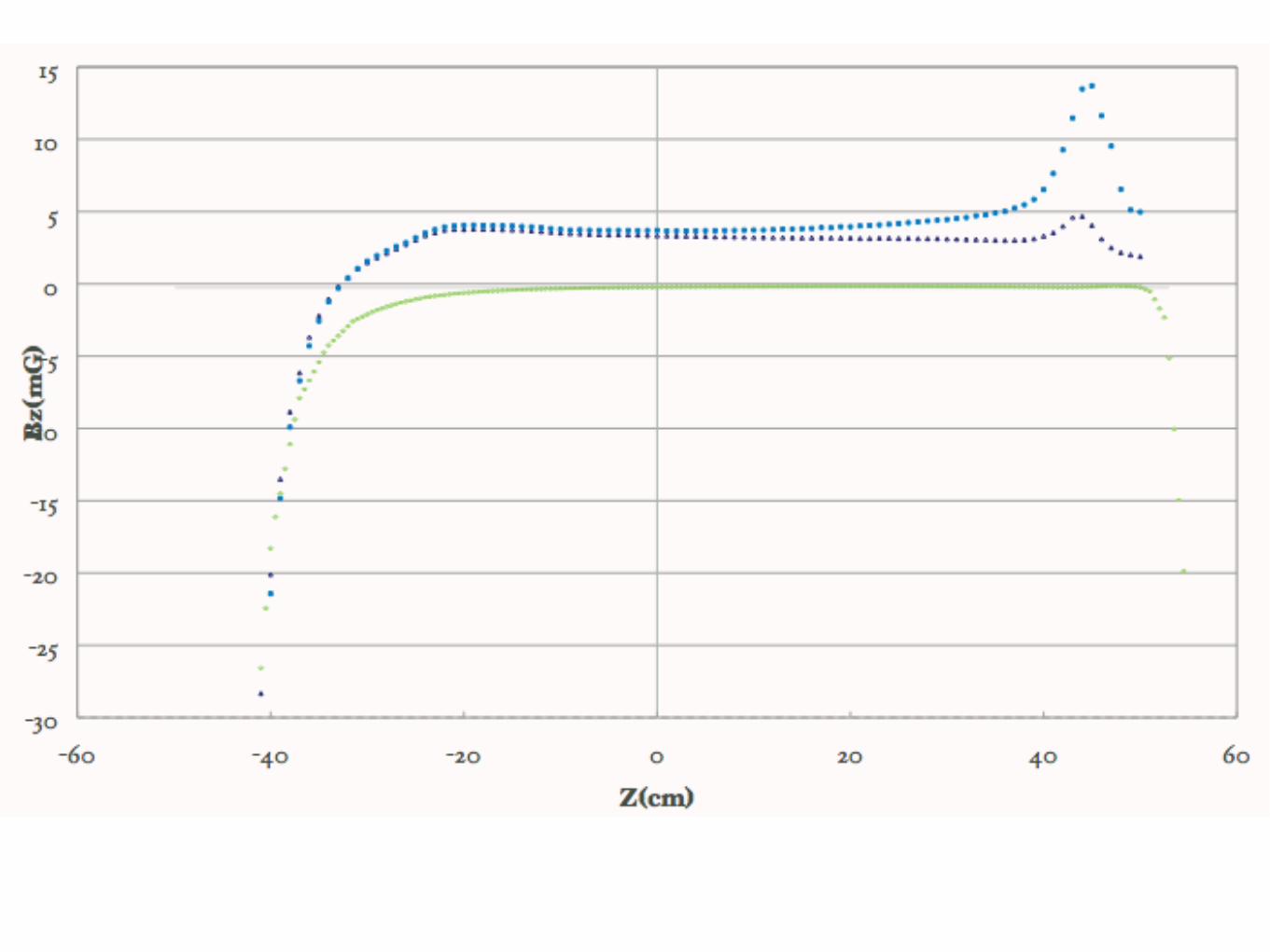
磁気シールドの下の穴の部分に煙突があるとき、ないときの比較
X
X
Z
Z
0
8060
4020
-20
-40
-60
-80
Only holes
Chimney
Z(c
m)
Z(c
m)
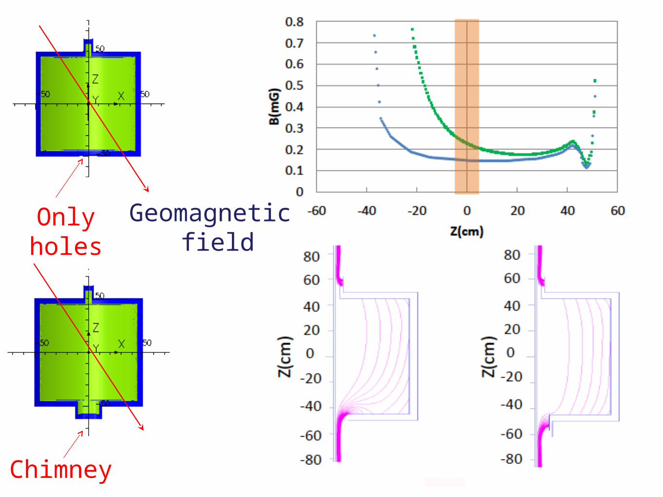
Geomagnetic field
Field simulation(OPERA-3d)
No of Layers Bz(nT) dBz/dz (nT/m)
1 -355.8 480.6
2 -27.2 55.4
3 -3.2 8.6
4 -0.7 2.9
Multi-layer suppression
X
Y
Geomagnetic field
Z
Y
Z
X
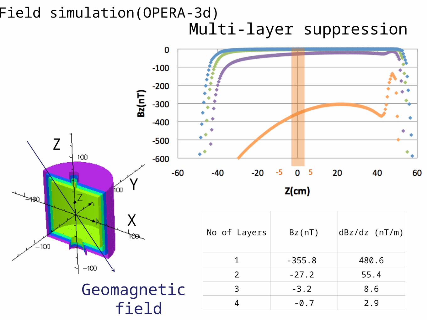
Compensation コイル
2D Magnetic field distribution for 2msize model
Bz(nT) dB/dz(nT/m)
No coil -0.73 2.89
2m size 0.03 1.68
4m size 0.0004 0.07
1nT
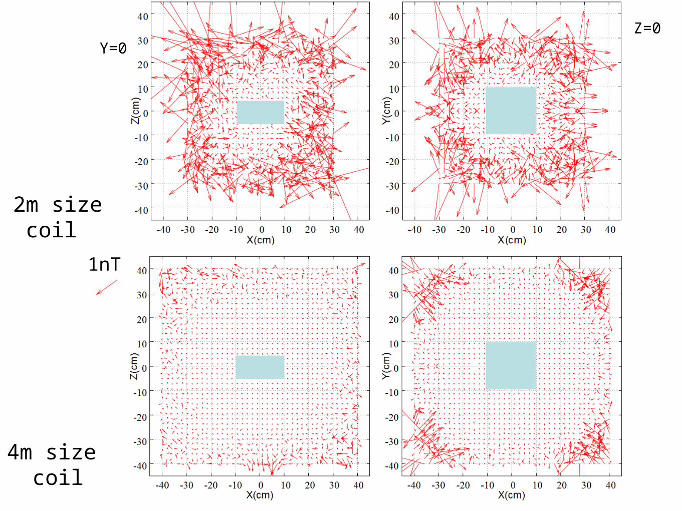
2m size coil
4m size coil
Y=0
Z=0
1nT
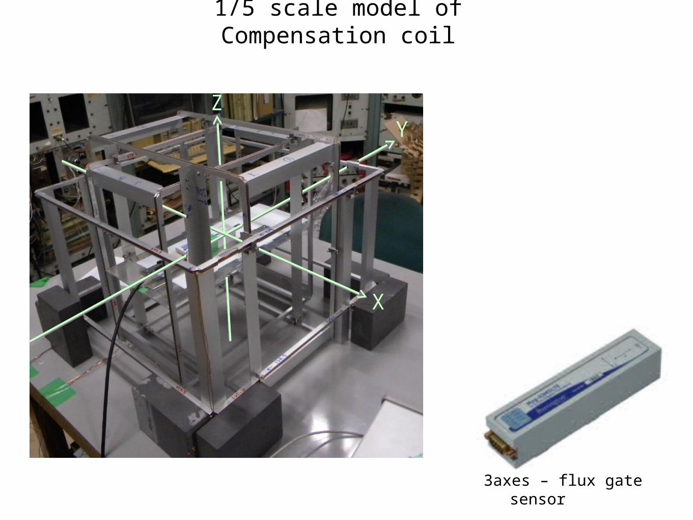
1/5 scale model of Compensation coil
3axes – flux gate sensor
X
ZY
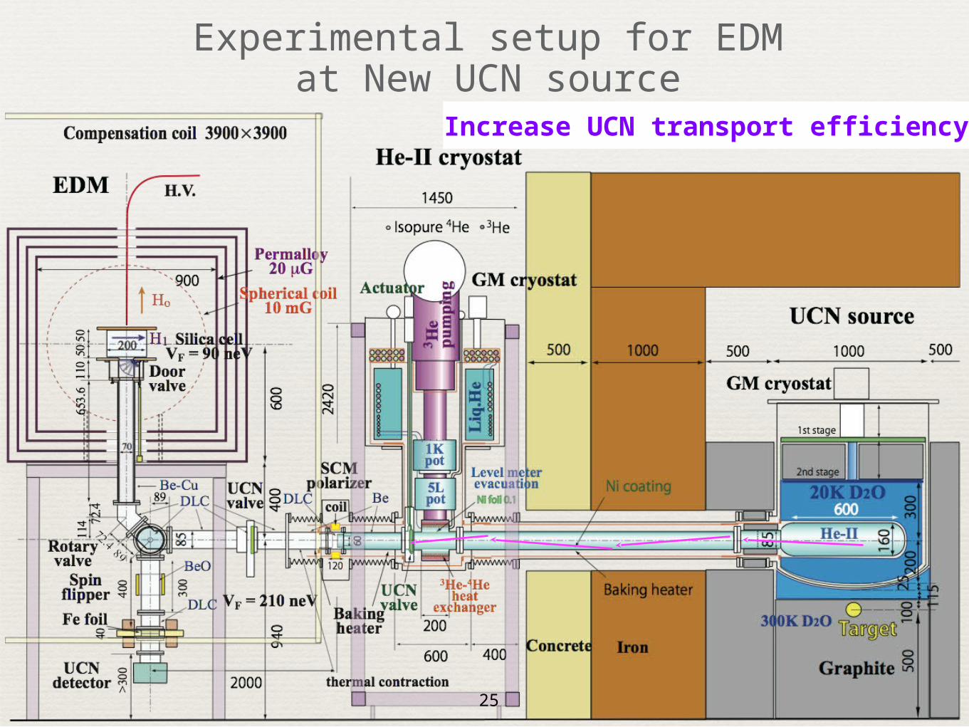
Experimental setup for EDMat New UCN source
Increase UCN transport efficiency
25
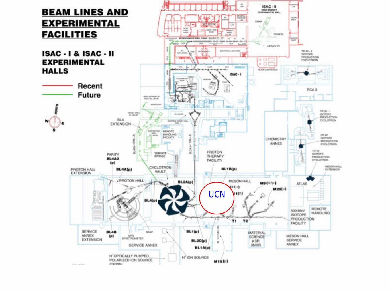
UCN

IEEE TRANSACTIONSON POWER APPARATUS AND SYSTEMS, VOL. PAS-88, 1969
10kV/cm
105
Extrapolation ?
Our data
Phys. Lett. A 376 (2012) 1347
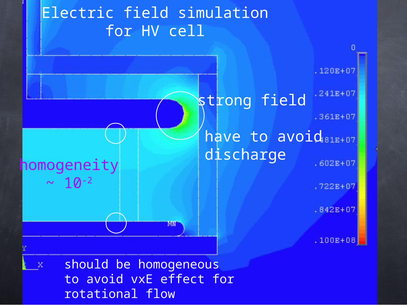
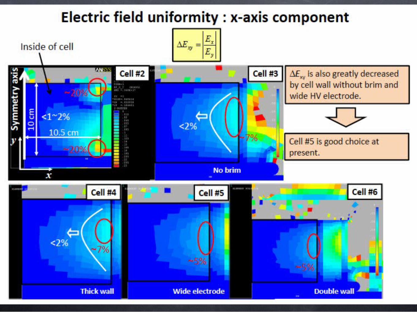
Electric field simulationfor HV cell
homogeneity~ 10-2
should be homogeneousto avoid vxE effect for rotational flow
strong field
have to avoiddischarge
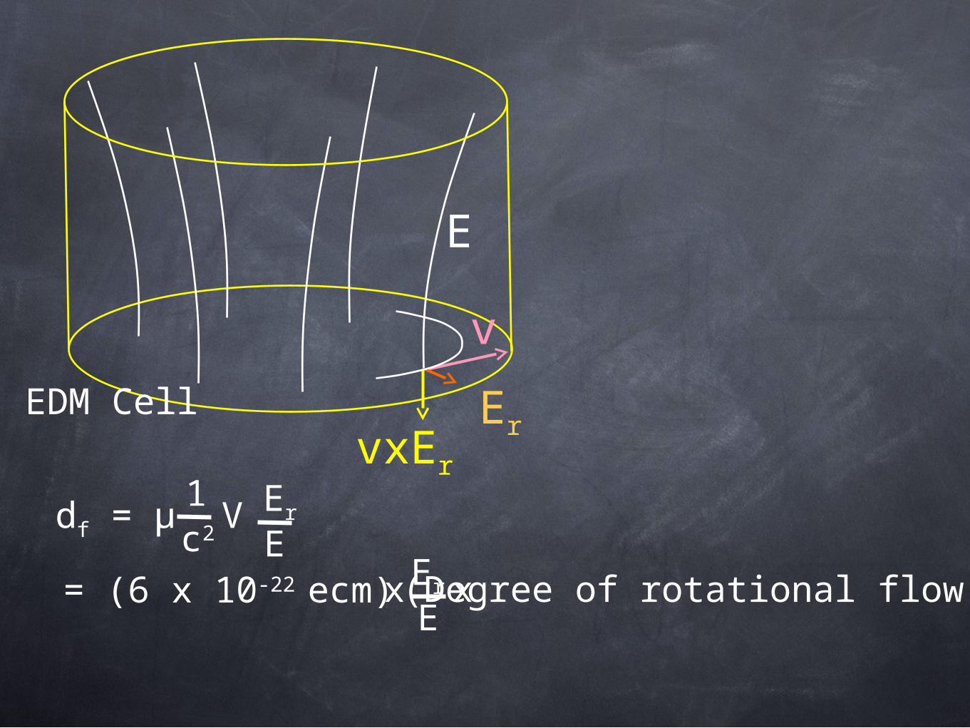
vxEr
v
ErEDM Cell
E
df = μc2
1V Er
E= (6 x 10-22 ecm) Er
Ex (Degree of rotational flow)x
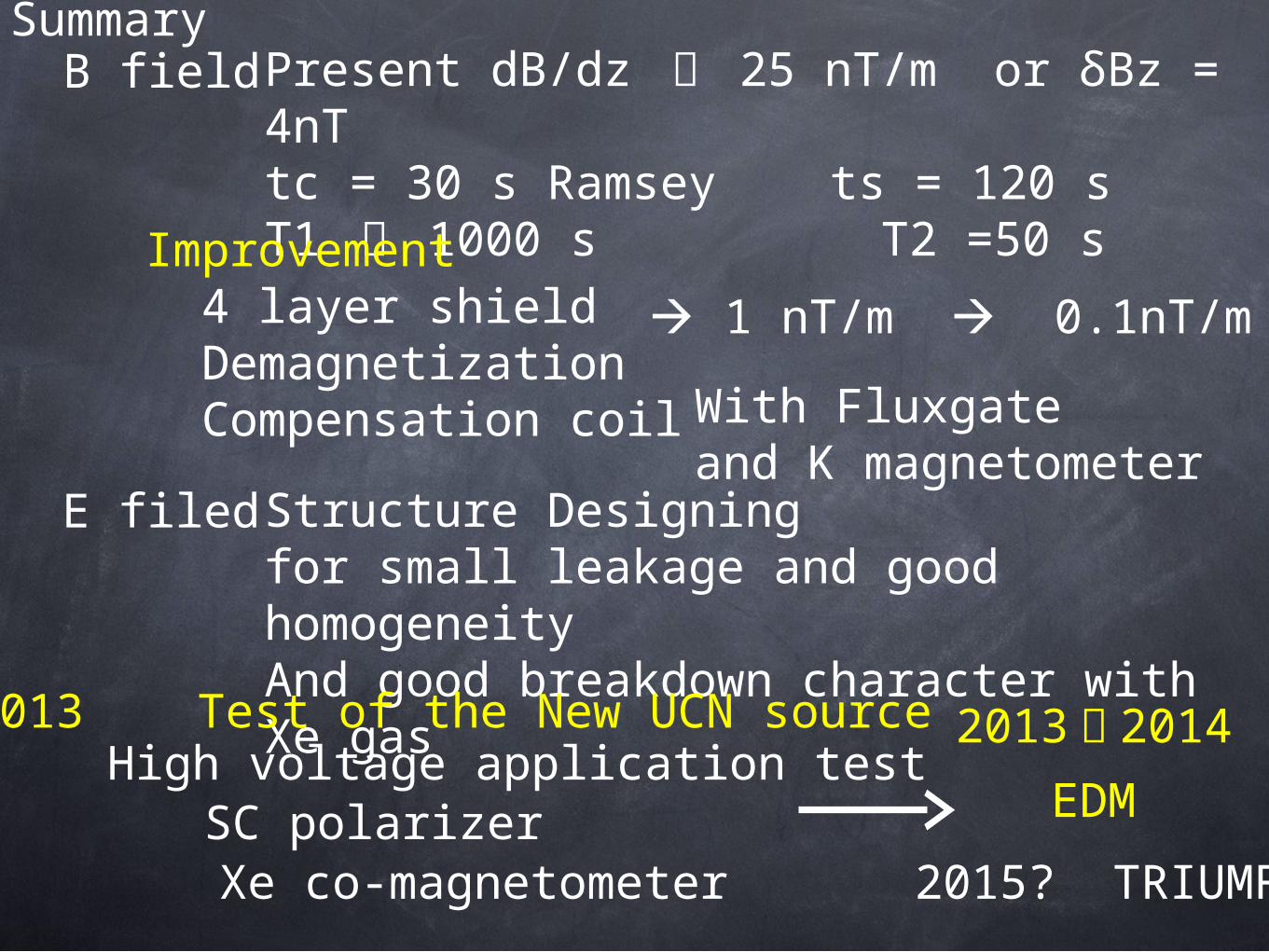
SummaryPresent dB/dz 〜 25 nT/m or δBz = 4nTtc = 30 s Ramsey ts = 120 sT1 〜 1000 s T2 =50 s
B field
Improvement 4 layer shield Demagnetization Compensation coil
E filed
1 nT/m 0.1nT/m
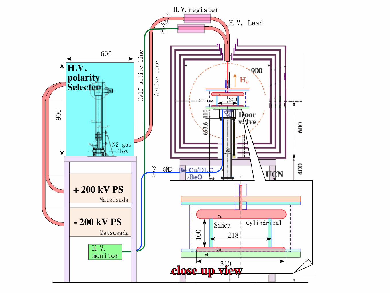
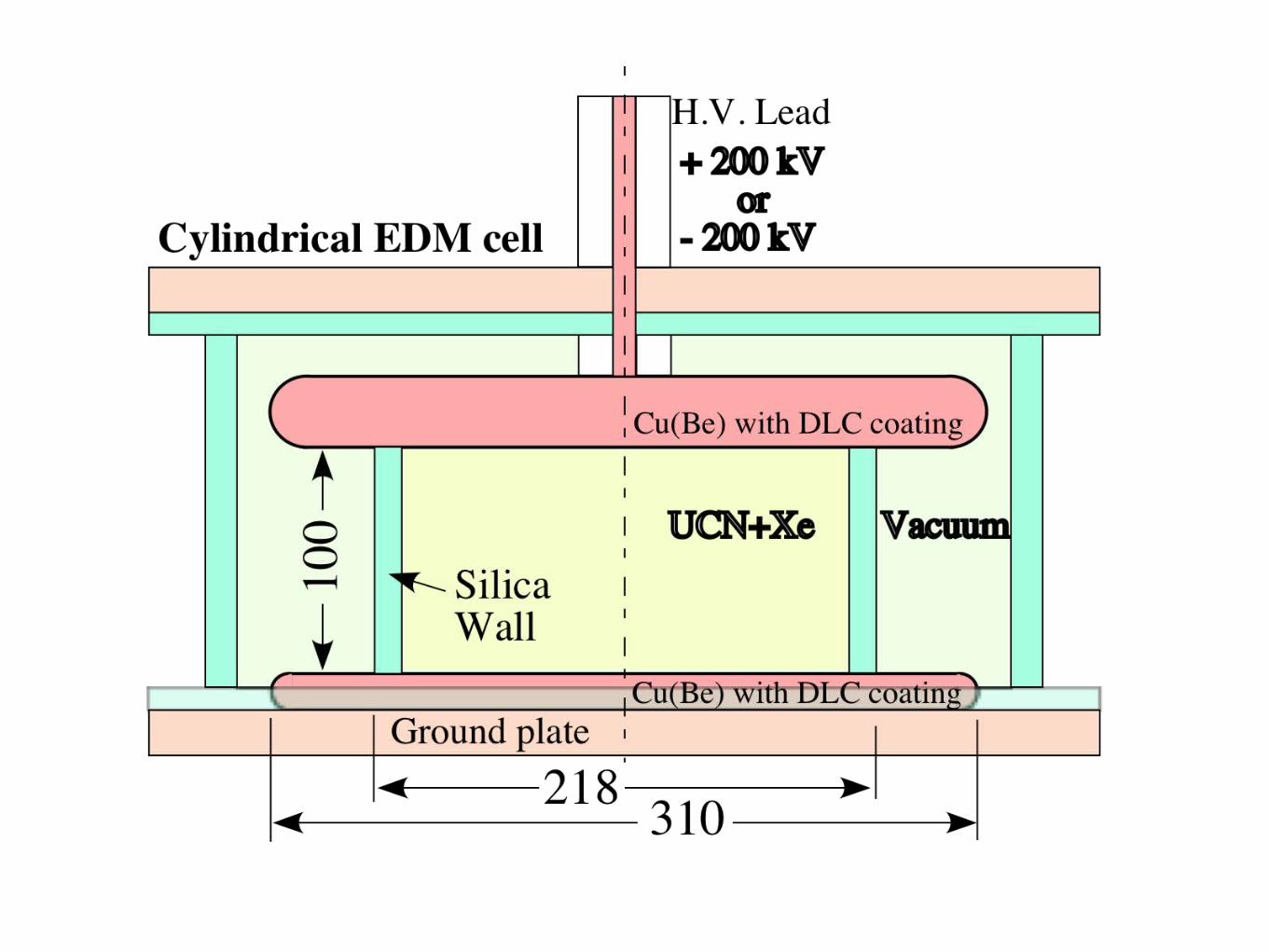
Structure Designingfor small leakage and good homogeneityAnd good breakdown character with Xe gas
Xe co-magnetometer
With Fluxgate and K magnetometer
2013 Test of the New UCN sourceHigh voltage application test
EDMSC polarizer
2013 〜 2014
2015? TRIUMF


![An lowerbound on the bounce action - KEK...2018. 12. 4 @ KEK-PH 2018 winter An lowerbound on the bounce action. Ryosuke Sato, Masahiro Takimoto [arXiv:1707.01099] Phys. Rev. Lett.](https://static.fdocument.org/doc/165x107/5f1cdcb630c86625ef5c9954/an-lowerbound-on-the-bounce-action-kek-2018-12-4-kek-ph-2018-winter-an.jpg)