Magnetic structure of -Co(OH)2 and the e · PDF file · 2016-10-07\Magnetic...
11
Electronic Supplementary Information, (ESI): “Magnetic structure of β -Co(OH) 2 and the effect of spin-orientation” Diego Hunt, Gast´ on Garbarino, Jos´ e Alberto Rodr´ ıguez-Velamaz´ an * , Valeria Ferrari, Mat´ ıas Jobbagy, and Damian A. Scherlis * E-mail: [email protected],[email protected] 1 Electronic Supplementary Material (ESI) for Physical Chemistry Chemical Physics. This journal is © the Owner Societies 2016
Transcript of Magnetic structure of -Co(OH)2 and the e · PDF file · 2016-10-07\Magnetic...
Electronic Supplementary Information, (ESI):
“Magnetic structure of β-Co(OH)2 and the effect
of spin-orientation”
Diego Hunt, Gaston Garbarino, Jose Alberto Rodrıguez-Velamazan∗, Valeria
Ferrari, Matıas Jobbagy, and Damian A. Scherlis∗
E-mail: [email protected],[email protected]
1
Electronic Supplementary Material (ESI) for Physical Chemistry Chemical Physics.This journal is © the Owner Societies 2016
Determination of the magnetic structure from the neu-
tron diffraction data
Representation analysis as described by Bertaut has been used to obtain possible configura-
tions of the magnetic structure compatible with this magnetic propagation vector and the
P-3m1 space group of β-Co(OH)2. The six irreducible representations Γ1 to Γ6 of the vector
group Gk (little group) were calculated using the program BasIreps, included in the FullProf
Suite.1 Γ1 to Γ4 are one-dimensional, while Γ5 and Γ6 are two-dimensional and have an imag-
inary part. An analysis of the imaginary representations shows that they can be transformed
in two two-dimensional physically irreducible representations. In the present case Γ5 and Γ6,
which are imaginary and two-dimensional, can be transformed to real matrices (Γ6 and Γ3,
respectively) by application of a unitary transformation (see Table S1).
Table 1: Physically irreducible representations of the space group P-3m1 for k =(0,0,0.5).The symmetry elements are written according to Seitzs notation. (a = 0.5 and b = 0.866)
1|000 3+00z|000 3−
00z|000 2xx0|000 20y0|000pΓ1 1 1 1 1 1pΓ2 1 1 1 -1 -1
pΓ3
[1 00 1
] [−a b−b −a
] [−a −bb −a
] [−a −b−b a
] [−a bb a
]pΓ4 1 1 1 1 1pΓ5 1 1 1 -1 -1
pΓ6
[1 00 1
] [−a b−b −a
] [−a −bb −a
] [−a −b−b a
] [−a bb a
]-1|000 -3+
00z|000 -3−00z|000 Mx2xz|000 Mx−xz|000 M2xxz|000
pΓ1 1 1 1 1 1 1pΓ2 1 1 1 -1 -1 -1
pΓ3
[1 00 1
] [−a b−b −a
] [−a −bb −a
] [1 00 −1
] [−a −b−b a
] [−a bb a
]pΓ4 -1 -1 -1 -1 -1 -1pΓ5 -1 -1 -1 1 1 1
pΓ6
[−1 00 −1
] [a −bb a
] [a b−b a
] [−1 00 −1
] [a bb −a
] [a −b−b −a
]
The magnetic representation ΓM for the magnetic site [1a Wyckoff position (0,0,0)] can
be decomposed as a direct sum of the physical irreducible representations pΓ2 and pΓ3,
2
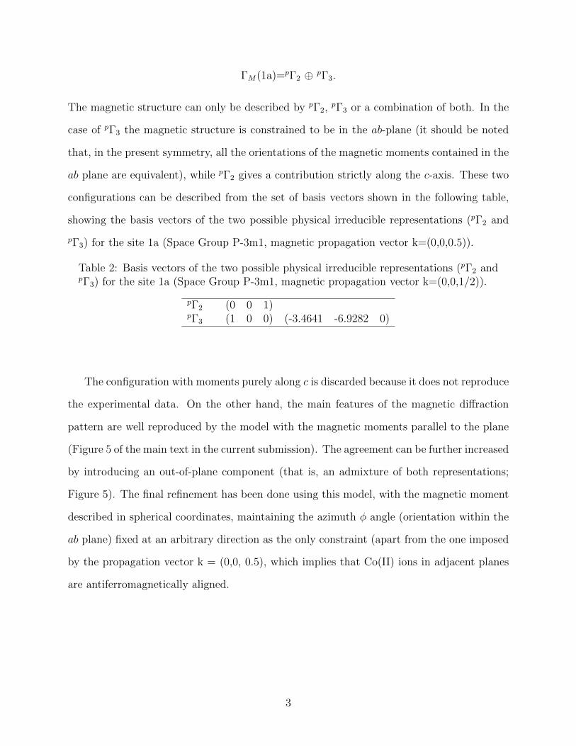
ΓM(1a)=pΓ2 ⊕ pΓ3.
The magnetic structure can only be described by pΓ2,pΓ3 or a combination of both. In the
case of pΓ3 the magnetic structure is constrained to be in the ab-plane (it should be noted
that, in the present symmetry, all the orientations of the magnetic moments contained in the
ab plane are equivalent), while pΓ2 gives a contribution strictly along the c-axis. These two
configurations can be described from the set of basis vectors shown in the following table,
showing the basis vectors of the two possible physical irreducible representations (pΓ2 and
pΓ3) for the site 1a (Space Group P-3m1, magnetic propagation vector k=(0,0,0.5)).
Table 2: Basis vectors of the two possible physical irreducible representations (pΓ2 andpΓ3) for the site 1a (Space Group P-3m1, magnetic propagation vector k=(0,0,1/2)).
pΓ2 (0 0 1)pΓ3 (1 0 0) (-3.4641 -6.9282 0)
The configuration with moments purely along c is discarded because it does not reproduce
the experimental data. On the other hand, the main features of the magnetic diffraction
pattern are well reproduced by the model with the magnetic moments parallel to the plane
(Figure 5 of the main text in the current submission). The agreement can be further increased
by introducing an out-of-plane component (that is, an admixture of both representations;
Figure 5). The final refinement has been done using this model, with the magnetic moment
described in spherical coordinates, maintaining the azimuth φ angle (orientation within the
ab plane) fixed at an arbitrary direction as the only constraint (apart from the one imposed
by the propagation vector k = (0,0, 0.5), which implies that Co(II) ions in adjacent planes
are antiferromagnetically aligned.
3
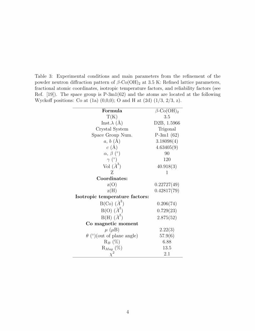
Table 3: Experimental conditions and main parameters from the refinement of thepowder neutron diffraction pattern of β-Co(OH)2 at 3.5 K: Refined lattice parameters,fractional atomic coordinates, isotropic temperature factors, and reliability factors (seeRef. [19]). The space group is P-3m1(62) and the atoms are located at the followingWyckoff positions: Co at (1a) (0,0,0); O and H at (2d) (1/3, 2/3, z).
Formula β-Co(OH)2T(K) 3.5
Inst.λ (A) D2B, 1.5966Crystal System Trigonal
Space Group Num. P-3m1 (62)a, b (A) 3.18098(4)c (A) 4.63405(9)α, β (◦) 90γ (◦) 120
Vol (A3) 40.918(3)
Z 1Coordinates:
z(O) 0.22727(49)z(H) 0.42817(79)
Isotropic temperature factors:
B(Co) (A2) 0.206(74)
B(O) (A2) 0.729(23)
B(H) (A2) 2.875(52)
Co magnetic momentµ (µB) 2.22(3)
θ (◦)(out of plane angle) 57.9(6)RB (%) 6.88
RMag (%) 13.5χ2 2.1
4
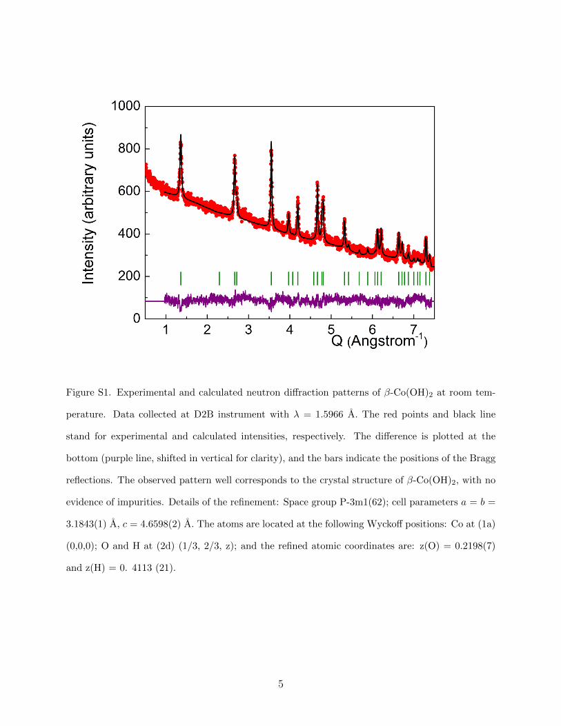
Figure S1. Experimental and calculated neutron diffraction patterns of β-Co(OH)2 at room tem-
perature. Data collected at D2B instrument with λ = 1.5966 A. The red points and black line
stand for experimental and calculated intensities, respectively. The difference is plotted at the
bottom (purple line, shifted in vertical for clarity), and the bars indicate the positions of the Bragg
reflections. The observed pattern well corresponds to the crystal structure of β-Co(OH)2, with no
evidence of impurities. Details of the refinement: Space group P-3m1(62); cell parameters a = b =
3.1843(1) A, c = 4.6598(2) A. The atoms are located at the following Wyckoff positions: Co at (1a)
(0,0,0); O and H at (2d) (1/3, 2/3, z); and the refined atomic coordinates are: z(O) = 0.2198(7)
and z(H) = 0. 4113 (21).
5
About the purity of the sample
The synthesis protocol, including a final step of mild drying of the washed sample, effectively
prevents the oxidation of Co(II). Only after two months exposed to ambient oxygen and
moisture conditions, the β-Co(OH)2 powder develops incipient oxidation, evidenced by a
pale brownish color instead of the inherent intense pink of the parent pure beta phase.
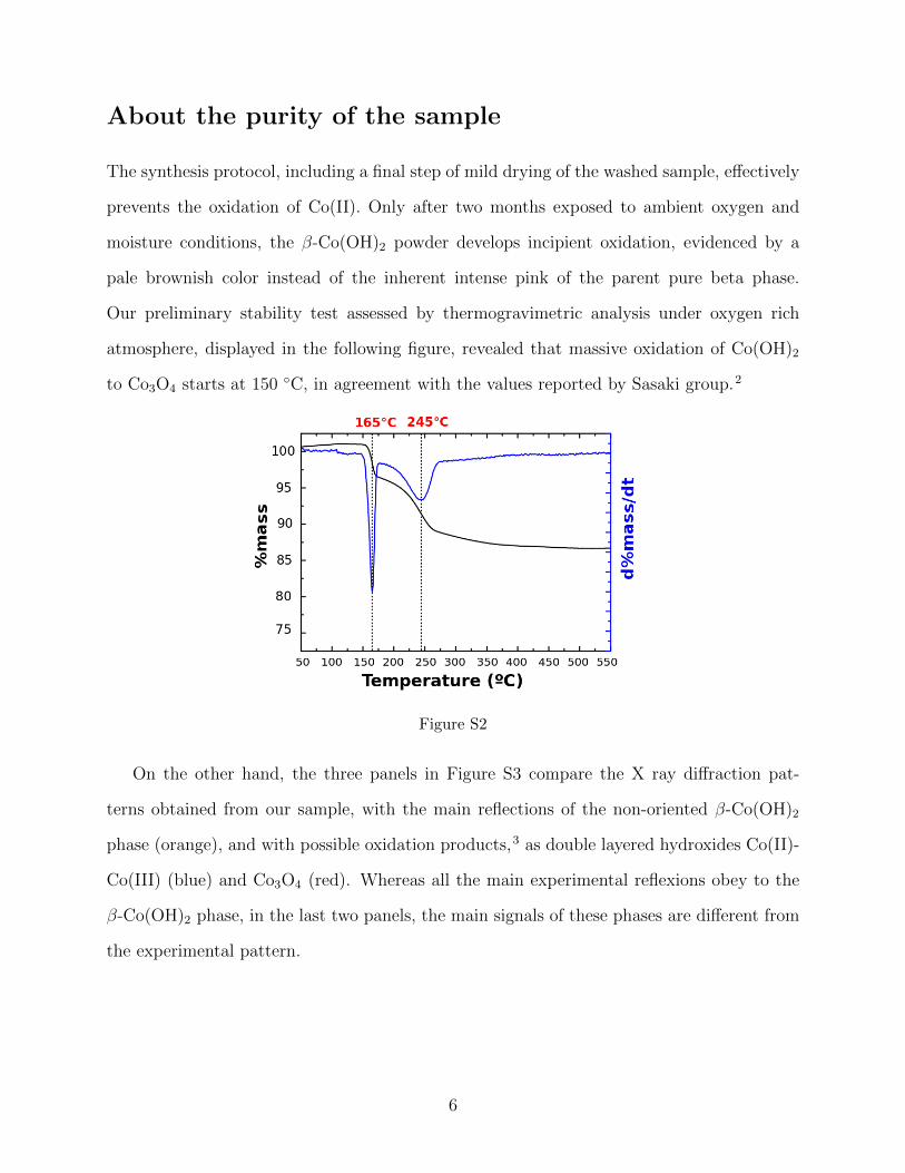
Our preliminary stability test assessed by thermogravimetric analysis under oxygen rich
atmosphere, displayed in the following figure, revealed that massive oxidation of Co(OH)2
to Co3O4 starts at 150 ◦C, in agreement with the values reported by Sasaki group.2
Figure S2
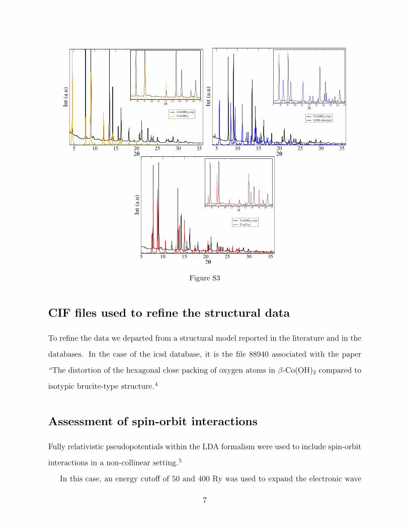
On the other hand, the three panels in Figure S3 compare the X ray diffraction pat-
terns obtained from our sample, with the main reflections of the non-oriented β-Co(OH)2
phase (orange), and with possible oxidation products,3 as double layered hydroxides Co(II)-
Co(III) (blue) and Co3O4 (red). Whereas all the main experimental reflexions obey to the
β-Co(OH)2 phase, in the last two panels, the main signals of these phases are different from
the experimental pattern.
6
5 10 15 20 25 30 352θ
Int(a.u)
Co(OH)2-exp
Co(OH)2
7 8 9 10 11 12 13 14 15 16 172θ
5 10 15 20 25 30 352θ
Int(a.u)
Co(OH)2-exp
LDH structure
7 8 9 10 11 12 13 14 15 16 172θ
5 10 15 20 25 30 352θ
Int(a.u)
Co(OH)2-exp
Co3Co4
7 8 9 10 11 12 13 14 15 16 172θ
Figure S3
CIF files used to refine the structural data
To refine the data we departed from a structural model reported in the literature and in the
databases. In the case of the icsd database, it is the file 88940 associated with the paper
“The distortion of the hexagonal close packing of oxygen atoms in β-Co(OH)2 compared to
isotypic brucite-type structure.4
Assessment of spin-orbit interactions
Fully relativistic pseudopotentials within the LDA formalism were used to include spin-orbit
interactions in a non-collinear setting.5
In this case, an energy cutoff of 50 and 400 Ry was used to expand the electronic wave
7
functions and the charge density, respectively, employing a 2×2×1 k-point mesh.
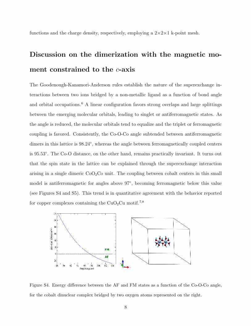
Discussion on the dimerization with the magnetic mo-
ment constrained to the c-axis
The Goodenough-Kanamori-Anderson rules establish the nature of the superexchange in-
teractions between two ions bridged by a non-metallic ligand as a function of bond angle
and orbital occupations.6 A linear configuration favors strong overlaps and large splittings
between the emerging molecular orbitals, leading to singlet or antiferromagnetic states. As
the angle is reduced, the molecular orbitals tend to equalize and the triplet or ferromagnetic
coupling is favored. Consistently, the Co-O-Co angle subtended between antiferromagnetic
dimers in this lattice is 98.24◦, whereas the angle between ferromagnetically coupled centers
is 95.53◦. The Co-O distance, on the other hand, remains practically invariant. It turns out
that the spin state in the lattice can be explained through the superexchange interaction
arising in a single dimeric CoO2Co unit. The coupling between cobalt centers in this small
model is antiferromagnetic for angles above 97◦, becoming ferromagnetic below this value
(see Figures S4 and S5). This trend is in quantitative agreement with the behavior reported
for copper complexes containing the CuO2Cu motif.7,8
Figure S4. Energy difference between the AF and FM states as a function of the Co-O-Co angle,
for the cobalt dinuclear complex bridged by two oxygen atoms represented on the right.
8
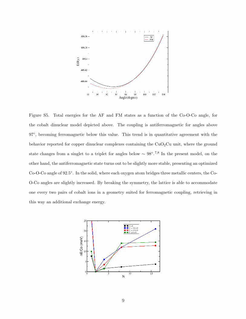
Figure S5. Total energies for the AF and FM states as a function of the Co-O-Co angle, for
the cobalt dinuclear model depicted above. The coupling is antiferromagnetic for angles above
97◦, becoming ferromagnetic below this value. This trend is in quantitative agreement with the
behavior reported for copper dinuclear complexes containing the CuO2Cu unit, where the ground
state changes from a singlet to a triplet for angles below ∼ 98◦.7,8 In the present model, on the
other hand, the antiferromagnetic state turns out to be slightly more stable, presenting an optimized
Co-O-Co angle of 92.5◦. In the solid, where each oxygen atom bridges three metallic centers, the Co-
O-Co angles are slightly increased. By breaking the symmetry, the lattice is able to accommodate
one every two pairs of cobalt ions in a geometry suited for ferromagnetic coupling, retrieving in
this way an additional exchange energy.
9
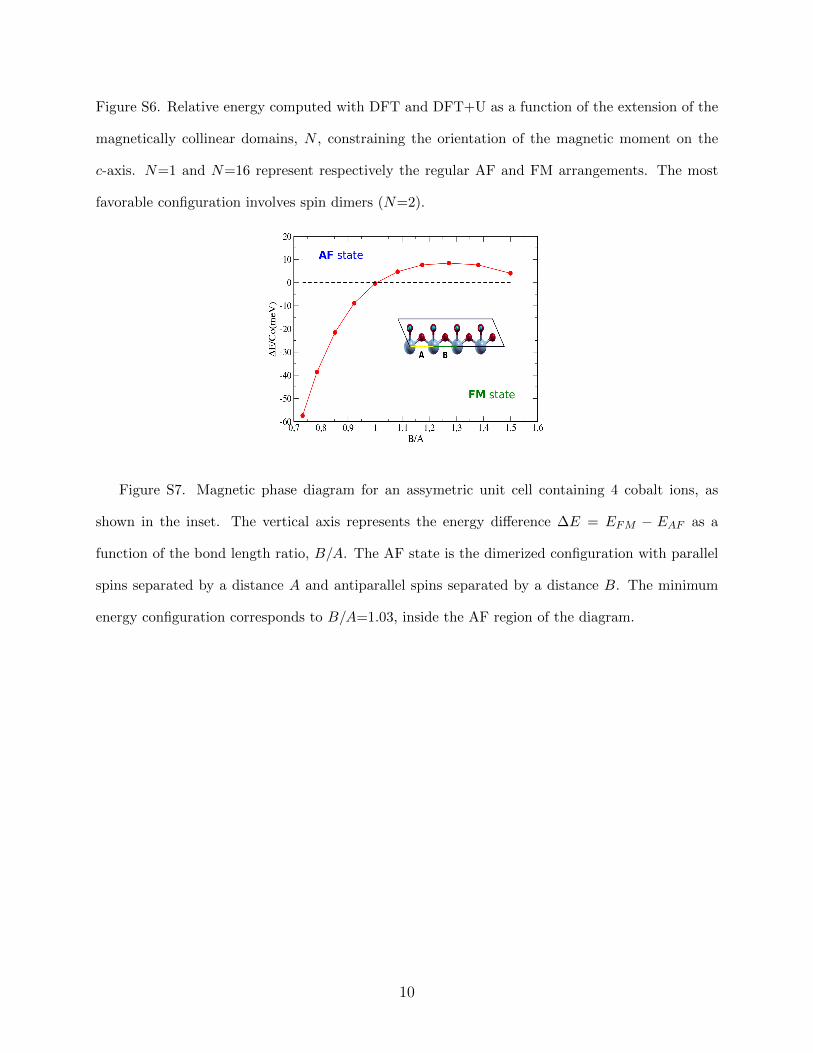
Figure S6. Relative energy computed with DFT and DFT+U as a function of the extension of the
magnetically collinear domains, N , constraining the orientation of the magnetic moment on the
c-axis. N=1 and N=16 represent respectively the regular AF and FM arrangements. The most
favorable configuration involves spin dimers (N=2).
Figure S7. Magnetic phase diagram for an assymetric unit cell containing 4 cobalt ions, as
shown in the inset. The vertical axis represents the energy difference ∆E = EFM − EAF as a
function of the bond length ratio, B/A. The AF state is the dimerized configuration with parallel
spins separated by a distance A and antiparallel spins separated by a distance B. The minimum
energy configuration corresponds to B/A=1.03, inside the AF region of the diagram.
10
References
(1) Rodrıguez-Carvajal, J. Phys. B (Amsterdam, Neth.) 1993, 192, 55–56.
(2) Liu, Z.; Ma, R.; Osada, M.; Takada, K.; Sasaki, T. J. Am. Chem. Soc. 2005, 127,
13869–13874.
(3) Ma, R.; Takada, K.; Fukuda, K.; Iyi, N.; Bando, Y.; Sasaki, T. Angew.Chem.Int.Ed.
2008, 47, 86–89.
(4) Pertlik, F. Monatsh. Chem. 1999, 130(9), 1083–1088.
(5) Dal Corso, A.; Mosca Conte, A. Phys. Rev. B 2005, 71, 115106.
(6) Goodenough, J. Magnetism and the Chemical Bond ; Interscience Publisher: New York,
1963.
(7) Hay, P.; Thibeault, J.; Hoffmann, R. J. Am. Chem. Soc. 1975, 97, 4884–4899.
(8) Hatfield, W. Inorg. Chem. 1983, 22, 833–837.
11
![Fullerene Derivatives (CN-[OH]β) and Carbon Nanotubes ...](https://static.fdocument.org/doc/165x107/627f787abc5d8f553f2a99ec/fullerene-derivatives-cn-oh-and-carbon-nanotubes-.jpg)