μm Accuracy by 500-mm Range - Omron
12
Smart Sensor Wide Laser Beam Measurement Sensor (Line Imaging Device Type) ZX-GT 10-μm Accuracy by 500-mm Range
Transcript of μm Accuracy by 500-mm Range - Omron
Smart SensorWide Laser Beam Measurement Sensor (Line Imaging Device Type) ZX-GT
10-μm Accuracy by 500-mm Range
32
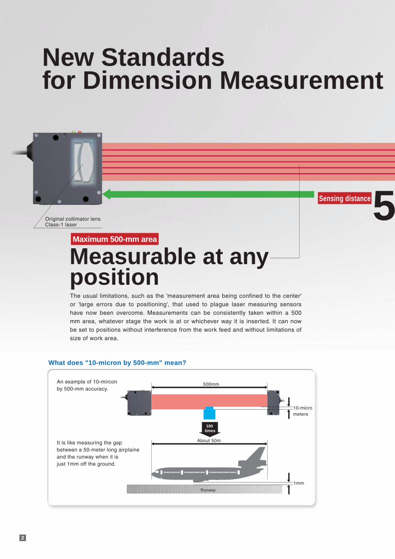
New Standards for Dimension Measurement
Sensing distance500mm
The usual limitations, such as the 'measurement area being confined to the center' or 'large errors due to positioning', that used to plague laser measuring sensors have now been overcome. Measurements can be consistently taken within a 500 mm area, whatever stage the work is at or whichever way it is inserted. It can now be set to positions without interference from the work feed and without limitations of size of work area.
Measurable at any position
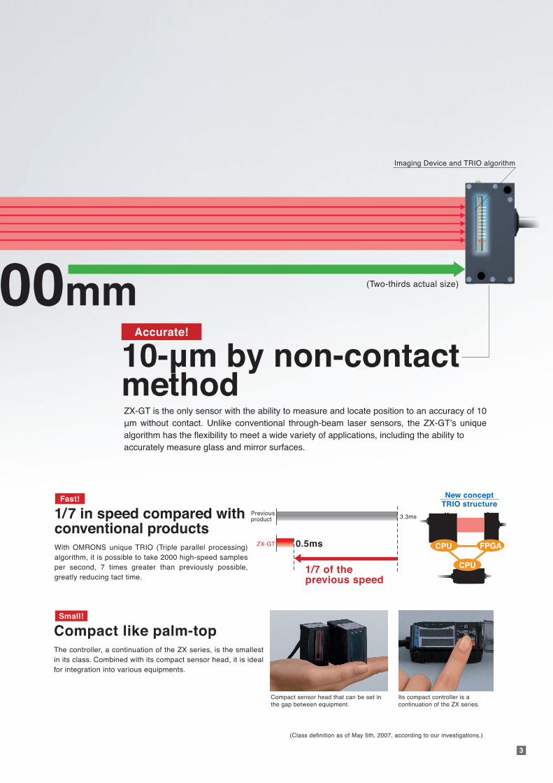
Accurate!
ZX-GT is the only sensor with the ability to measure and locate position to an accuracy of 10 µm without contact. Unlike conventional through-beam laser sensors, the ZX-GT’s unique algorithm has the flexibility to meet a wide variety of applications, including the ability to accurately measure glass and mirror surfaces.
10-µm by non-contact method
Compact like palm-topThe controller, a continuation of the ZX series, is the smallest in its class. Combined with its compact sensor head, it is ideal for integration into various equipments.
Its compact controller is a continuation of the ZX series.
Compact sensor head that can be set in the gap between equipment.
(Class definition as of May 5th, 2007, according to our investigations.)
Fast!
Small!
FPGA
CPU
CPU
1/7 in speed compared with conventional productsWith OMRONS unique TRIO (Triple parallel processing) algorithm, it is possible to take 2000 high-speed samples per second, 7 times greater than previously possible, greatly reducing tact time.
ZX-GT
Previousproduct 3.3ms
0.5ms
1/7 of the previous speed
New conceptTRIO structure
10-micrometers
500mm
About 50m
Runway
1mm
100 times
An example of 10-mircon by 500-mm accuracy.
What does "10-micron by 500-mm" mean?
It is like measuring the gap between a 50-meter long airplaine and the runway when it is just 1mm off the ground.
(Two-thirds actual size)
Original collimator lensClass-1 laser
CCD and TRIO algorithm
Maximum 500-mm area
C M Y K
3
00mmAccurate!
Compact like palm-topThe controller, a continuation of the ZX series, is the smallest in its class. Combined with its compact sensor head, it is ideal for integration into various equipments.
Its compact controller is a continuation of the ZX series.
Compact sensor head that can be set in the gap between equipment.
(Class definition as of May 5th, 2007, according to our investigations.)
Fast!
Small!
FPGA
CPU
CPU
1/7 in speed compared with conventional productsWith OMRONS unique TRIO (Triple parallel processing) algorithm, it is possible to take 2000 high-speed samples per second, 7 times greater than previously possible,greatly reducing tact time.
ZX-GT
Previousproduct 3.3ms
0.5ms
1/7 of the previous speed
New conceptTRIO structure
(Two-thirds actual size)
Imaging Device and TRIO algorithm
ZX-GT is the only sensor with the ability to measure and locate position to an accuracy of 10 μm without contact. Unlike conventional through-beam laser sensors, the ZX-GT’s unique algorithm has the flexibility to meet a wide variety of applications, including the ability toaccurately measure glass and mirror surfaces.
10-μm by non-contactmethod
Imaging Device
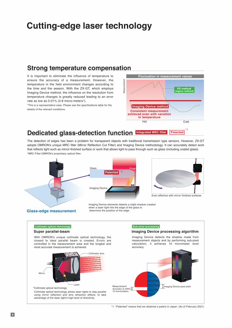
Imaging Device elements detects a slight shadow created when a laser light hits the edge of the glass to determine the position of the edge.
Glass Edge
Cutting-edge laser technology
Strong temperature compensationIt is important to eliminate the influence of temperature to ensure the accuracy of a measurement. However, the temperature in the field environment changes according to the time and the season. With the ZX-GT, which employs Imaging Device method, the influence on the resolution from temperature changes is greatly reduced leading to an error rate as low as 0.01% (2.8 micro-meters*).*This is a representative case. Please see the specifications table for the
details of the relevant conditions.
Dedicated glass-detection functionThe detection of edges has been a problem for transparent objects with traditional transmission type sensors. However, ZX-GT adopts OMRON's unique MRC filter (Mirror Reflection Cut Filter) and Imaging Device methodology. It can accurately detect work that reflects light such as mirror-finished surface or work that allows light to pass through such as glass (including coated glass). *MRC Filter:OMRON's proprietary optical filter.
4
Hot
Fluctuation in measurement values
Me
asu
rem
en
tCold
*1
Consistent measurementachieved even with variation
in temperature
PD method(legacy method)
PatentedIntegrated MRC filter
Imaging Device method
Super parallel-beam
With OMRON's unique collimate optical technology, the closest to ideal parallel beam is created. Errors are controlled in the measurement area and the longest and most accurate measurement is achieved.
Collimate optical technology allows laser lights to stay parallelusing mirror reflection and lens refraction effects, to takeadvantage of the laser light's high-level of directivity.
Collimate optical technology
Imaging Device processing algorithmImaging Device detects the shadow made from measurement objects and by performing sub-pixel calculation, it achieves 10 micrometer level accuracy.
Sub-pixel processing
Laser
Collimator lens
Mirror
Measurementaccuracy is within 10 micrometers
Imaging Device pixel pitch
Even effective with mirror finished surfaces
*1. “Patented” means that we obtained a patent in Japan. (As of February 2021)
Glass-edge measurement
*Collimate optical technology
*1Patented
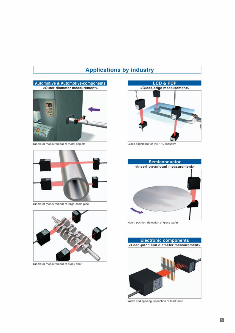
Applications by industry
5
Diameter measurement of metal objects
Diameter measurement of large-scale pipe
Diameter measurement of crank shaft
Width and spacing inspection of leadframe
Electronic components<Lead-pitch and diameter measurement>
Glass alignment for the FPD industry
LCD & PDP<Glass-edge measurement>
Notch position detection of glass wafer
Semiconductor<Insertion-amount measurement>
Automotive & Automotive-components<Outer diameter measurement>
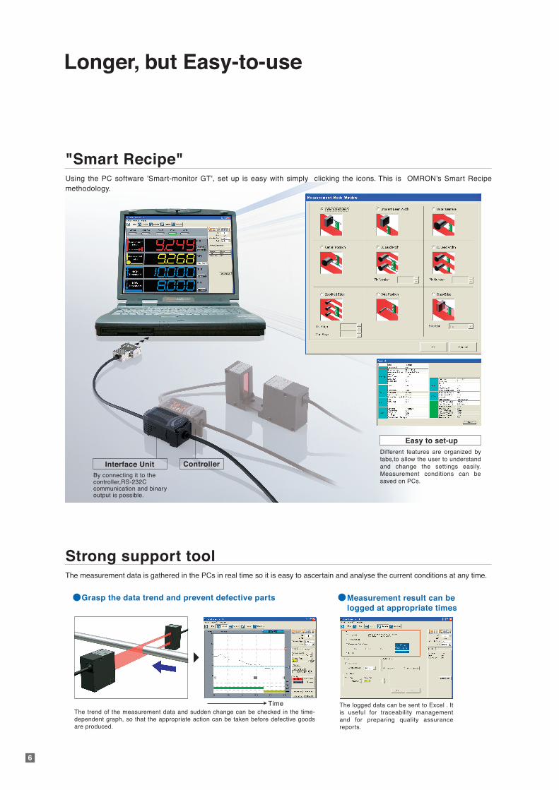
Longer, but Easy-to-use
"Smart Recipe"Using the PC software 'Smart-monitor GT', set up is easy with simply clicking the icons. This is OMRON's Smart Recipe methodology.
6
Strong support toolThe measurement data is gathered in the PCs in real time so it is easy to ascertain and analyse the current conditions at any time.
Interface Unit Controller
Different features are organized bytabs,to allow the user to understand and change the settings easily.Measurement conditions can be saved on PCs.
By connecting it to the controller,RS-232Ccommunication and binaryoutput is possible.
Easy to set-up
Grasp the data trend and prevent defective parts Measurement result can be logged at appropriate times
The logged data can be sent to Excel . It is useful for traceability management and for preparing quality assurancereports.
The trend of the measurement data and sudden change can be checked in the time-dependent graph, so that the appropriate action can be taken before defective goods are produced.
Time
7
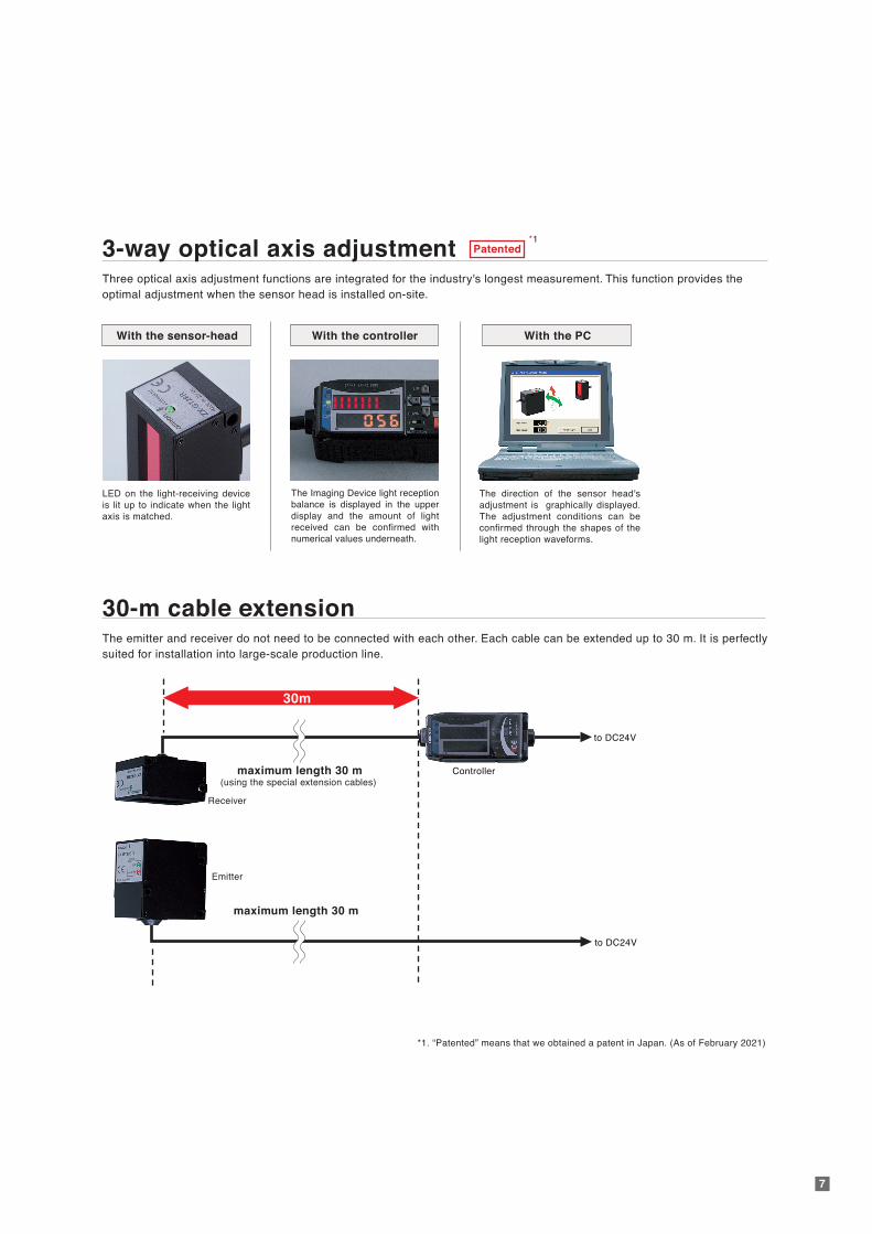
3-way optical axis adjustmentThree optical axis adjustment functions are integrated for the industry's longest measurement. This function provides the optimal adjustment when the sensor head is installed on-site.
30-m cable extensionThe emitter and receiver do not need to be connected with each other. Each cable can be extended up to 30 m. It is perfectlysuited for installation into large-scale production line.
LED on the light-receiving deviceis lit up to indicate when the light axis is matched.
The Imaging Device light reception balance is displayed in the upper display and the amount of light received can be confirmed with numerical values underneath.
The direction of the sensor head's adjustment is graphically displayed.The adjustment conditions can be confirmed through the shapes of the light reception waveforms.
With the sensor-head With the controller With the PC
Receiver
Emitter
Controller
to DC24V
to DC24V
(using the special extension cables)maximum length 30 m
maximum length 30 m
30m
*1Patented
*1. “Patented” means that we obtained a patent in Japan. (As of February 2021)
8
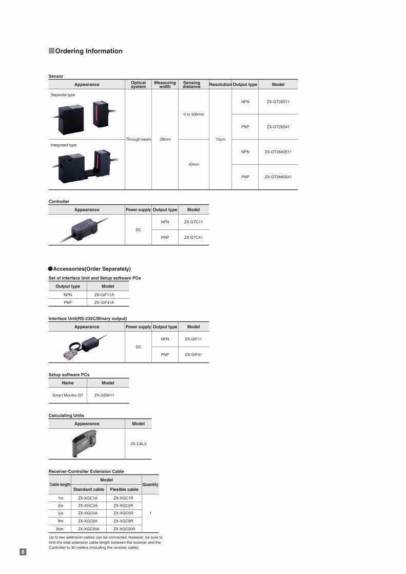
Ordering Information
Sensor
Accessories(Order Separately)
Appearance
Separate type
Integrated type
Through-beam
DC
28mm
0 to 500mm
10µm
NPN
PNP ZX-GT28S41
NPN ZX-GT2840S11
PNP ZX-GT2840S41
ZX-GT28S11
40mm
Measuringwidth
Opticalsystem
Sensingdistance Resolution Output type Model
Controller
Appearance Output type
NPN
Power supply Model
ZX-GTC11
PNP ZX-GTC41
DC
Interface Unit(RS-232C/Binary output)
Appearance Output type
NPN
Power supply Model
ZX-GIF11
PNP ZX-GIF41
Set of Interface Unit and Setup software PCs
ZX-CAL2
Calculating Units
Appearance Model
Output type
NPN
Model
ZX-GIF11A
PNP ZX-GIF41A
Setup software PCs
Name
Smart Monitor GT
Model
ZX-GSW11
Receiver-Controller Extension Cable
Cable length
ZX-XGC1A
ZX-XGC2A
ZX-XGC5A
ZX-XGC8A
ZX-XGC20A
ZX-XGC1R
1
ZX-XGC2R
ZX-XGC5R
ZX-XGC8R
ZX-XGC20R
1m
2m
5m
8m
20m
Model
Standard cable Flexible cableQuantity
Up to two extension cables can be connected. However, be sure to limit the total extension cable length between the receiver and the Controller to 30 meters (including the receiver cable).
98
Ordering Information Specifications
Sensor
Accessories(Order Separately)
Sensor
Appearance
Separate type
Integrated type
Through-beam
DC
28mm
0 to 500mm
10µm
NPN
PNP ZX-GT28S41
NPN ZX-GT2840S11
PNP ZX-GT2840S41
ZX-GT28S11
40mm
Measuringwidth
Opticalsystem
Sensingdistance Resolution Output type Model
Controller
Appearance Output type
NPN
Power supply Model
ZX-GTC11
PNP ZX-GTC41
DC
Interface Unit(RS-232C/Binary output)
Appearance Output type
NPN
Power supply Model
ZX-GIF11
PNP ZX-GIF41
Set of Interface Unit and Setup software PCs
ZX-CAL2
Calculating Units
Appearance Model
Output type
NPN
Model
ZX-GIF11A
PNP ZX-GIF41A
Setup software PCs
Name
Smart Monitor GT
Model
ZX-GSW11
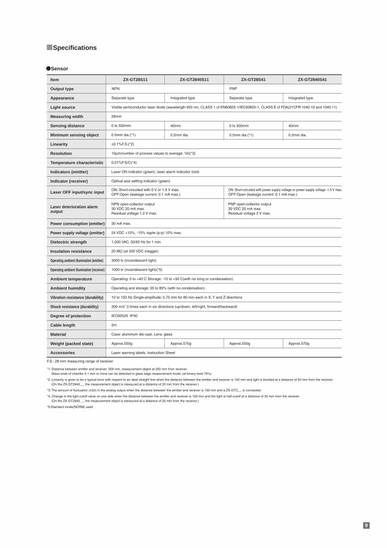
ON: Short-circuited with 0 V or 1.5 V max.OFF:Open (leakage current: 0.1 mA max.)
ON: Short-circuited with power supply voltage or power supply voltage -1.5 V max.OFF:Open (leakage current: 0.1 mA max.)
*1: Distance between emitter and receiver: 500 mm, measurement object at 250 mm from receiver. Glass ends of chamfer 0.1 mm or more can be detected in glass edge measurement mode. (at binary level 70%)
*2: Linearity is given to be a typical error with respect to an ideal straight line when the distance between the emitter and receiver is 100 mm and light is blocked at a distance of 50 mm from the receiver. (On the ZX-GT2840__, the measurement object is measured at a distance of 20 mm from the receiver.)
*3: The amount of fluctuation (±3σ) in the analog output when the distance between the emitter and receiver is 100 mm and a ZX-GTC__ is connected
*4: Change in the light cutoff value on one side when the distance between the emitter and receiver is 100 mm and the light is half-cutoff at a distance of 50 mm from the receiver (On the ZX-GT2840__, the measurement object is measured at a distance of 20 mm from the receiver.)
*5:Standard mode(NORM) used
NPN open-collector output30 VDC 20 mA max.Residual voltage 1.2 V max.
PNP open-collector output30 VDC 20 mA max.Residual voltage 2 V max.
Item ZX-GT28S11 ZX-GT2840S11 ZX-GT2840S41ZX-GT28S41
Output type
Appearance Separate type Integrated type Separate type Integrated type
28mm
Light source
Measuring width
±0.1%F.S.(*2)Linearity
10µm(number of process values to average: 16)(*3)Resolution
0.01%F.S/C(*4)Temperature characteristic
Laser ON indicator (green), laser alarm indicator (red)Indicators (emitter)
Optical axis setting indicator (green)Indicator (receiver)
30 mA max.Power consumption (emitter)
24 VDC +10%, -15% ripple (p-p) 10% max.Power supply voltage (emitter)
1,000 VAC, 50/60 Hz for 1 minDielectric strength
20 MΩ (at 500 VDC megger)Insulation resistance
3000 lx (incandescent light)Operating ambient illumination (emitter)
1000 lx (incandescent light)(*5)Operating ambient illumination (receiver)
Operating: 0 to +40 C Storage: -15 to +50 C(with no icing or condensation)Ambient temperature
Operating and storage: 35 to 85% (with no condensation)Ambient humidity
10 to 150 Hz Single-amplitude: 0.75 mm for 80 min each in X, Y and Z directionsVibration resistance (durability)
300 m/s2 3 times each in six directions (up/down, left/right, forward/backward)Shock resistance (durability)
IEC60529 IP40Degree of protection
2mCable length
Case: aluminum die-cast, Lens: glassMaterial
Weight (packed state)
Laser warning labels, Instruction Sheet
F.S.: 28 mm measuring range of receiver
Accessories
Laser OFF input/sync input
Laser deterioration alarmoutput
Sensing distance
Minimum sensing object
Visible semiconductor laser diode (wavelength 650 nm, CLASS 1 of EN60825-1/IEC60825-1, CLASS of FDA(21CFR 1040.10 and 1040.11)
NPN PNP
0 to 500mm 40mm 40mm0 to 500mm
0.5mm dia.(*1) 0.2mm dia. 0.2mm dia.0.5mm dia.(*1)
Approx.550g Approx.570g Approx.570gApprox.550g
Receiver-Controller Extension Cable
Cable length
ZX-XGC1A
ZX-XGC2A
ZX-XGC5A
ZX-XGC8A
ZX-XGC20A
ZX-XGC1R
1
ZX-XGC2R
ZX-XGC5R
ZX-XGC8R
ZX-XGC20R
1m
2m
5m
8m
20m
Model
Standard cable Flexible cableQuantity
Up to two extension cables can be connected. However, be sure to limit the total extension cable length between the receiver and the Controller to 30 meters (including the receiver cable).
10
Specifications
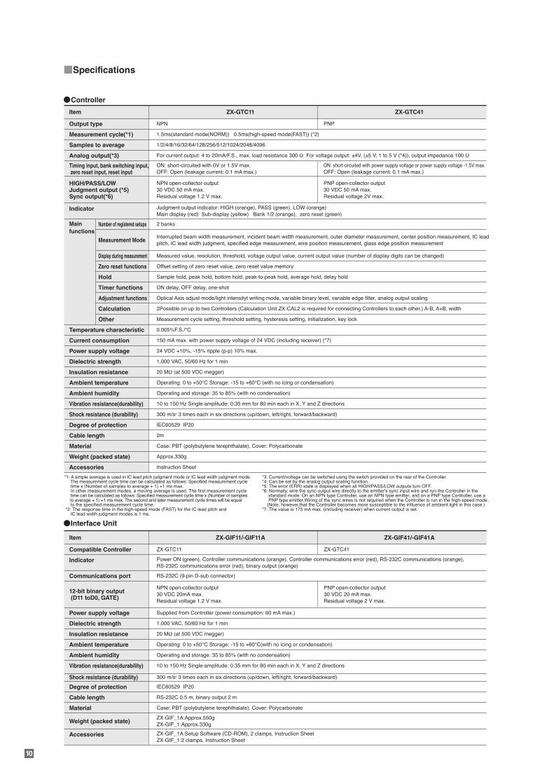
Controller
Item ZX-GTC11 ZX-GTC41
Output type
Measurement cycle(*1) 1.5ms(standard mode(NORM)) 0.5ms(high-speed mode(FAST)) (*2)
ON: short-circuited with 0V or 1.5V max.OFF: Open (leakage current: 0.1 mA max.)
ON: short-circuited with power supply voltage or power supply voltage -1.5V max.OFF: Open (leakage current: 0.1 mA max.)
For current output: 4 to 20mA/F.S., max. load resistance 300 Ω For voltage output: ±4V, (±5 V, 1 to 5 V (*4)), output impedance 100 Ω
2 banks
Interrupted beam width measurement, incident beam width measurement, outer diameter measurement, center position measurement, IC lead pitch, IC lead width judgment, specified edge measurement, wire position measurement, glass edge position measurement
Measured value, resolution, threshold, voltage output value, current output value (number of display digits can be changed)
Offset setting of zero reset value, zero reset value memory
Sample hold, peak hold, bottom hold, peak-to-peak hold, average hold, delay hold
ON delay, OFF delay, one-shot
Optical Axis adjust mode/light intensityt writing mode, variable binary level, variable edge filter, analog output scaling
2Possible on up to two Controllers (Calculation Unit ZX-CAL2 is required for connecting Controllers to each other.) A-B, A+B, width
Measurement cycle setting, threshold setting, hysteresis setting, initialization, key lock
0.005%F.S./°C
150 mA max. with power supply voltage of 24 VDC (including receiver) (*7)
24 VDC +10%, -15% ripple (p-p) 10% max.
1,000 VAC, 50/60 Hz for 1 min
20 MΩ (at 500 VDC megger)
Operating: 0 to +50°C Storage: -15 to +60°C (with no icing or condensation)
Operating and storage: 35 to 85% (with no condensation)
10 to 150 Hz Single-amplitude: 0.35 mm for 80 min each in X, Y and Z directions
IEC60529 IP20
300 m/s2 3 times each in six directions (up/down, left/right, forward/backward)Shock resistance (durability)
Samples to average
Analog output(*3)
Indicator
Temperature characteristic
Main
functionsNumber of registered setups
Measurement Mode
Display during measurement
Zero reset functions
Hold
Timer functions
Adjustment functions
Calculation
Current consumption
Power supply voltage
Dielectric strength
Insulation resistance
Ambient temperature
Ambient humidity
Vibration resistance(durability)
Degree of protection
2mCable length
Case: PBT (polybutylene terephthalate), Cover: PolycarbonateMaterial
Approx.330gWeight (packed state)
Instruction SheetAccessories
*1: A simple average is used in IC lead pitch judgment mode or IC lead width judgment mode. The measurement cycle time can be calculated as follows: Specified measurement cycle time x (Number of samples to average + 1) +1 ms max. In other measurement modes, a moving average is used. The first measurement cycle time can be calculated as follows: Specified measurement cycle time x (Number of samples to average + 1) +1 ms max. The second and later measurement cycle times will be equal to the specified measurement cycle time. *2: The response time in the high-speed mode (FAST) for the IC lead pitch and IC lead width judgment modes is 1 ms.
*3: Current/voltage can be switched using the switch provided on the rear of the Controller.*4: Can be set by the analog output scaling function.*5: The error (ERR) state is displayed when all HIGH/PASS/LOW outputs turn OFF.*6: Normally, wire the sync output wire directly to the emitter's sync input wire and run the Controller in the standard mode. On an NPN type Controller, use an NPN type emitter, and on a PNP type Controller, use a PNP type emitter.Wiring of the sync wires is not required when the Controller is run in the high-speed mode. (Note, however,that the Controller becomes more susceptible to the influence of ambient light in this case.) *7: The value is 175 mA max. (including receiver) when current output is set.
Other
Timing input, bank switching input, zero reset input, reset input
HIGH/PASS/LOWJudgment output (*5)Sync output(*6)
NPN open-collector output30 VDC 50 mA max.Residual voltage 1.2 V max.
Judgment output indicator: HIGH (orange), PASS (green), LOW (orange)Main display (red) Sub-display (yellow) Bank 1/2 (orange), zero reset (green)
PNP open-collector output30 VDC 50 mA max.Residual voltage 2V max.
1/2/4/8/16/32/64/128/256/512/1024/2048/4096
NPN PNP
Interface Unit
Item ZX-GIF11/-GIF11A
Compatible Controller
Indicator Power ON (green), Controller communications (orange), Controller communications error (red), RS-232C communications (orange), RS-232C communications error (red), binary output (orange)
ZX-GTC11 ZX-GTC41
Communications port
12-bit binary output (D11 toD0, GATE)
RS-232C (9-pin D-sub connector)
Power supply voltage Supplied from Controller (power consumption: 60 mA max.)
Dielectric strength 1,000 VAC, 50/60 Hz for 1 min
Insulation resistance 20 MΩ (at 500 VDC megger)
Ambient temperature Operating: 0 to +50°C Storage: -15 to +60°C(with no icing or condensation)
Ambient humidity Operating and storage: 35 to 85% (with no condensation)
Vibration resistance(durability)
300 m/s2 3 times each in six directions (up/down, left/right, forward/backward)Shock resistance (durability)
10 to 150 Hz Single-amplitude: 0.35 mm for 80 min each in X, Y and Z directions
Degree of protection IEC60529 IP20
Cable length RS-232C 0.5 m, binary output 2 m
Material Case: PBT (polybutylene terephthalate), Cover: Polycarbonate
Weight (packed state)ZX-GIF_1A:Approx.550gZX-GIF_1:Approx.330g
Accessories ZX-GIF_1A:Setup Software (CD-ROM), 2 clamps, Instruction SheetZX-GIF_1:2 clamps, Instruction Sheet
NPN open-collector output30 VDC 20mA max.Residual voltage 1.2 V max.
PNP open-collector output30 VDC 20 mA max.Residual voltage 2 V max.
ZX-GIF41/-GIF41A
11
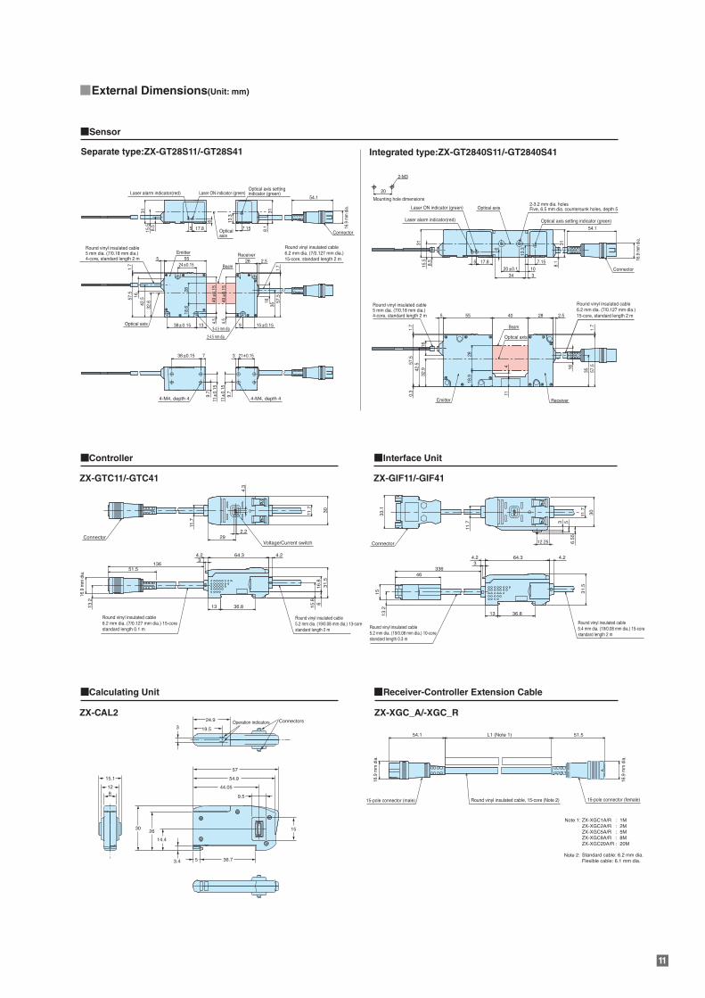
External Dimensions(Unit: mm)
Sensor
Controller Interface Unit
Separate type:ZX-GT28S11/-GT28S41
ZX-GTC11/-GTC41
Calculating Unit
ZX-CAL2 ZX-XGC_A/-XGC_R
ZX-GIF11/-GIF41
Receiver-Controller Extension Cable
Integrated type:ZX-GT2840S11/-GT2840S41
13.2
15
46336
13 36.8
4.23
64.3 4.2
31.5
3033.1
11.7 3 5
6.55
12.25
11.7
51.5136
13.2
13 36.8
34.2 64.3 4.2
15.8
16.8
31.5
306
Round vinyl insulated cable6.2 mm dia. (7/0.127 mm dia.) 15-corestandard length 0.1 m
Round vinyl insulated cable5.2 mm dia. (19/0.08 mm dia.) 13-corestandard length 2 m Round vinyl insulated cable
5.2 mm dia. (19/0.08 mm dia.) 10-corestandard length 0.3 m
Round vinyl insulated cable5.4 mm dia. (19/0.08 mm dia.) 15-corestandard length 2 m
11.7
11.7
4.3
2.229Connector
ConnectorVoltage/Current switch
L1 (Note 1)
Note 1:
Note 2:
ZX-XGC1A/R : 1MZX-XGC2A/R : 2MZX-XGC5A/R : 5MZX-XGC8A/R : 8MZX-XGC20A/R
Standard cable: 6.2 mm dia.Flexible cable: 6.1 mm dia.
: 20M
54.1 51.5
15-pole connector (male) 15-pole connector (female)Round vinyl insulated cable, 15-core (Note 2)
32.6
18.6
28
55524±0.15
38± 0.15 13
4.5
49±0
.15
49±
0.15
4.5
9 15±0.15
28 2.516
3542.5
1657.5
57.5
1.71.7
Optical axis
Receiver
Beam
Beam3-4.5 mm dia.
2-4.5 mm dia.
Round vinyl insulated cable5 mm dia. (7/0.18 mm dia.)4-core, standard length 2 m
Round vinyl insulated cable5 mm dia. (7/0.18 mm dia.)4-core, standard length 2 m
Round vinyl insulated cable6.2 mm dia. (7/0.127 mm dia.)15-core, standard length 2 m
Round vinyl insulated cable6.2 mm dia. (7/0.127 mm dia.)15-core, standard length 2 m
Emitter
ReceiverEmitter
15.5
8.1
8.5
31
54.1
16.9
mm
dia
.
16.9
mm
dia
.
16.9
mm
dia
.
16.9
mm
dia
.
16.9
mm
dia
.
7.1517.85
6 13.3
31
Connector
Connector
Opticalaxis
Optical axis
Optical axis setting indicator (green)Laser ON indicator (green)Laser alarm indicator(red)
Laser alarm indicator(red)11
±0.
15
21±0.153
9.7
38±0.15
11±
0.15
9.7
7
4-M4, depth 4 4-M4, depth 4
28
32.9
18.9
114
555 40 28 2.5
16
35
1642
.557.5
0.3
57.5
1.7
1.7
15.5
20
20±0.1 10334
8.5
31
8.1
54.1
31
17.85
6
13.3
7.15
Optical axis2-3.2 mm dia. holesFive, 6.5 mm dia. countersunk holes, depth 5
2-M3
Mounting hole dimensions
Optical axis setting indicator (green)
Laser ON indicator (green)
24.9 Operation indicators Connectors
19.53
9.5
15
44.05
30
15.1
128
26
14.4
3.4 36.75
54.9
57
Safety Precautions for Laser Equipment
CAUTION
Do not expose your eyes to laser radiation either directly or reflected from a mirroredsurface.The emitted laser beams have a high power density and direct exposure may result in lossof eyesight.
The warning and explanatory labelon the side of the Sensor Head inthe ZX-GT Series is in Japanese.Replace it with the English labelthat comes with the product.
This document provides information mainly for selecting suitable models. Please read the User's Manual carefully for information that the usermust understand and accept before purchase, including information on warranty, limitations of liability, and precautions.
Authorized Distributor:
In the interest of product improvement, specifications are subject to change without notice.
Cat. No. Q154-E1 0421
© OMRON Corporation 2009-2021 All Rights Reserved.
OMRON Corporation Industrial Automation Company
OMRON ELECTRONICS LLC2895 Greenspoint Parkway, Suite 200 Hoffman Estates, IL 60169 U.S.A.Tel: (1) 847-843-7900/Fax: (1) 847-843-7787
Regional HeadquartersOMRON EUROPE B.V.Wegalaan 67-69, 2132 JD HoofddorpThe NetherlandsTel: (31)2356-81-300/Fax: (31)2356-81-388
Contact: www.ia.omron.comKyoto, JAPAN
OMRON ASIA PACIFIC PTE. LTD.No. 438A Alexandra Road # 05-05/08 (Lobby 2), Alexandra Technopark, Singapore 119967Tel: (65) 6835-3011/Fax: (65) 6835-2711
OMRON (CHINA) CO., LTD.Room 2211, Bank of China Tower, 200 Yin Cheng Zhong Road, PuDong New Area, Shanghai, 200120, ChinaTel: (86) 21-5037-2222/Fax: (86) 21-5037-2200
CSM_3_2
![C18, C18-WP, HFC18-16, HFC18-30,RP-AQUA, …1].pdfChromaNik Technologies Inc. SunShell 2 μm, 2.6 μm, 3.4 μm and 5 μm HPLC column Core Shell Particle C18, C18-WP, HFC18-16, HFC18-30,RP-AQUA,](https://static.fdocument.org/doc/165x107/5be363f509d3f24a208d0dd6/c18-c18-wp-hfc18-16-hfc18-30rp-aqua-1pdfchromanik-technologies-inc-sunshell.jpg)


![NaOCl [μM] - MDPI](https://static.fdocument.org/doc/165x107/62607d508c664043d559d161/naocl-m-mdpi.jpg)