Lower Hybrid: Progress and Plans - psfc.mit.edu · rapid formation of titanium hydride. Formation...
21
Lower Hybrid: Progress and Plans Ron Parker Alcator C-Mod Program Advisory Committee Meeting January 24-26, 2007
Transcript of Lower Hybrid: Progress and Plans - psfc.mit.edu · rapid formation of titanium hydride. Formation...
Lower Hybrid: Progress and Plans
Ron Parker
Alcator C-Mod Program Advisory Committee MeetingJanuary 24-26, 2007

Motivation for Applying Lower Hybrid Current Drive in Alcator C-Mod1 is to Produce and Study Fully Steady-state High Performance Regimes
Ip = 0.98 MA, IBS = 0.7 MA, ILH = 0.28 MAβn = 2.9, HITER-89 = 2.5 (assumed)
PLH = 2.4 MW, ηLHCD = 0.1, n|| = 2.75 PICRF = 4 MW
1P. T. Bonoli, M. Porkolab, J. Ramos, et. al., PPCF 39,(1997)223; P.T. Bonoli, R.R.Parker, M. Porkolab, et.al., Nucl Fus 40,(2000)1251
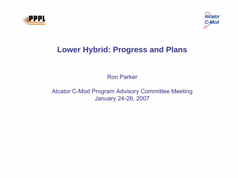
The Original 96 Waveguide Grill (Ti) was Replaced with Grill Fabricated From Stainless Steel
Probes
Ti grill as installed in January 2005
This grill quickly deteriorated due torapid formation of titanium hydride.
Formation of TiH could be problematic for ITER – Needs further study
Stainless steel grill installed in January 2006 as it looked at the end of Alcator C-Mod campaign in July 2006.
(close inspection shows only 88 waveguides!)
Limiters
LHCD Experiments Made Good Progress in 2006 Run Campaign
Highlights:
~ 1 MW net coupled, Γ2 ~ 15%
Reasonable agreement with Brambilla coupling code with vacuum gap
Nearly 1 MA driven, n19IR/P ~ 3
Sawtooth stabilization, central heating observed
Generally good agreement with GENRAY/CQL3D model regarding total current, hard X-Ray and cyclotron emission synthetic diagnostics. X-Ray profiles broader than code prediction
Experimental results so far are in-line with requirements forhigh performance SS operation.
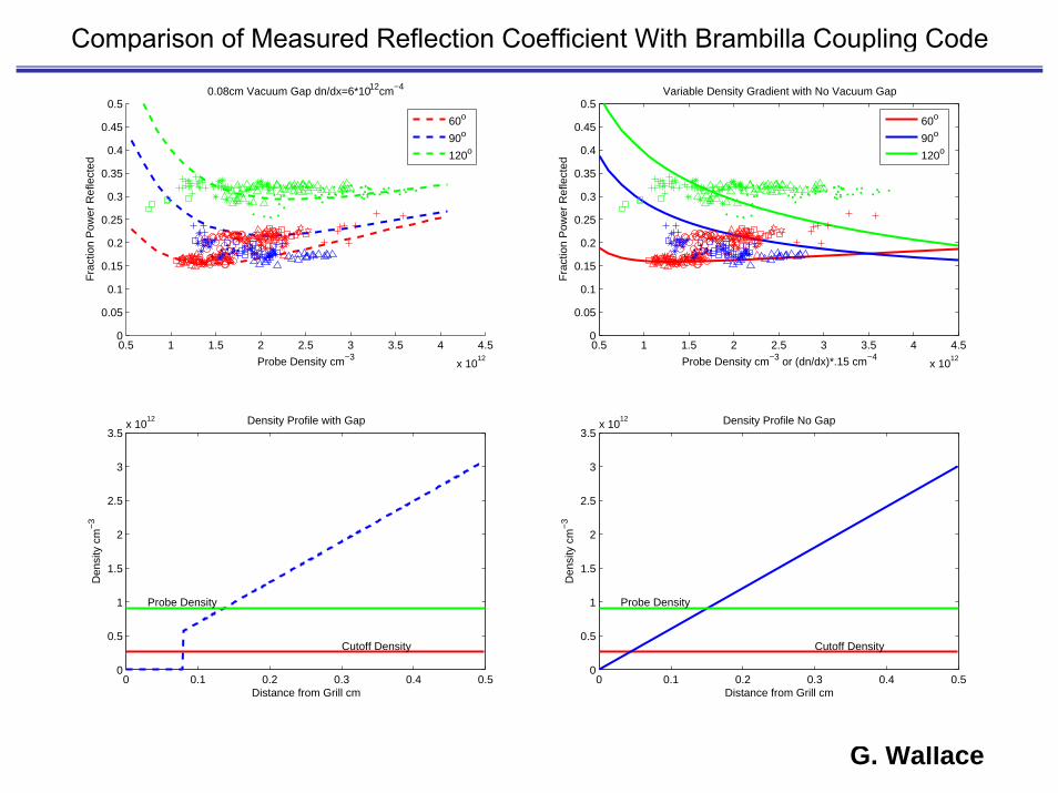
Comparison of Measured Reflection Coefficient With Brambilla Coupling Code
G. Wallace
0.5 1 1.5 2 2.5 3 3.5 4 4.5
x 1012
0
0.05
0.1
0.15
0.2
0.25
0.3
0.35
0.4
0.45
0.5
Probe Density cm−3
Fra
ctio
n P
ower
Ref
lect
ed0.08cm Vacuum Gap dn/dx=6*1012cm−4
0.5 1 1.5 2 2.5 3 3.5 4 4.5
x 1012
0
0.05
0.1
0.15
0.2
0.25
0.3
0.35
0.4
0.45
0.5
Probe Density cm−3 or (dn/dx)*.15 cm−4
Fra
ctio
n P
ower
Ref
lect
ed
Variable Density Gradient with No Vacuum Gap
0 0.1 0.2 0.3 0.4 0.50
0.5
1
1.5
2
2.5
3
3.5x 10
12
Den
sity
cm
−3
Distance from Grill cm
Density Profile No Gap
Cutoff Density
Probe Density
0 0.1 0.2 0.3 0.4 0.50
0.5
1
1.5
2
2.5
3
3.5x 10
12
Den
sity
cm
−3
Distance from Grill cm
Density Profile with Gap
Cutoff Density
Probe Density
60o
90o
120o
60o
90o
120o
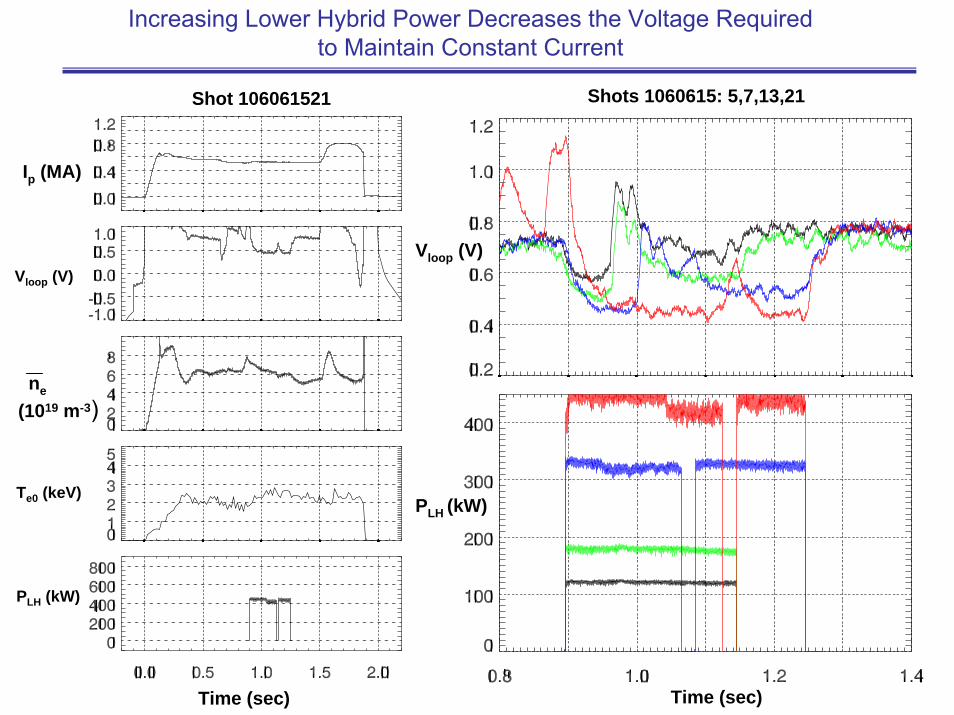
Ip (MA)
Vloop (V)
ne
(1019 m-3)
Te0 (keV)
PLH (kW)
Vloop (V)
PLH (kW)
Time (sec) Time (sec)
Shot 106061521 Shots 1060615: 5,7,13,21
Increasing Lower Hybrid Power Decreases the Voltage Required to Maintain Constant Current
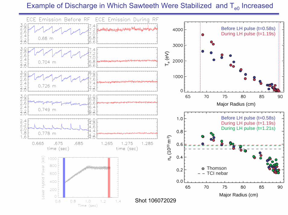
Major Radius (cm)
n e (1
020
m-3
)
During LH pulse (t=1.19s)During LH pulse (t=1.21s)
Before LH pulse (t=0.58s)
TCI nebarThomson
During LH pulse (t=1.19s)Before LH pulse (t=0.58s)
Major Radius (cm)
T e (e
V)
Example of Discharge in Which Sawteeth Were Stabilized and Te0 Increased
Shot 106072029
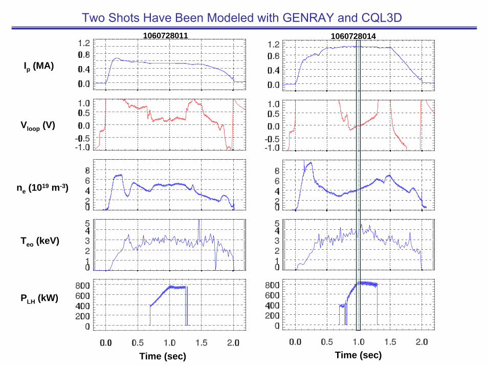
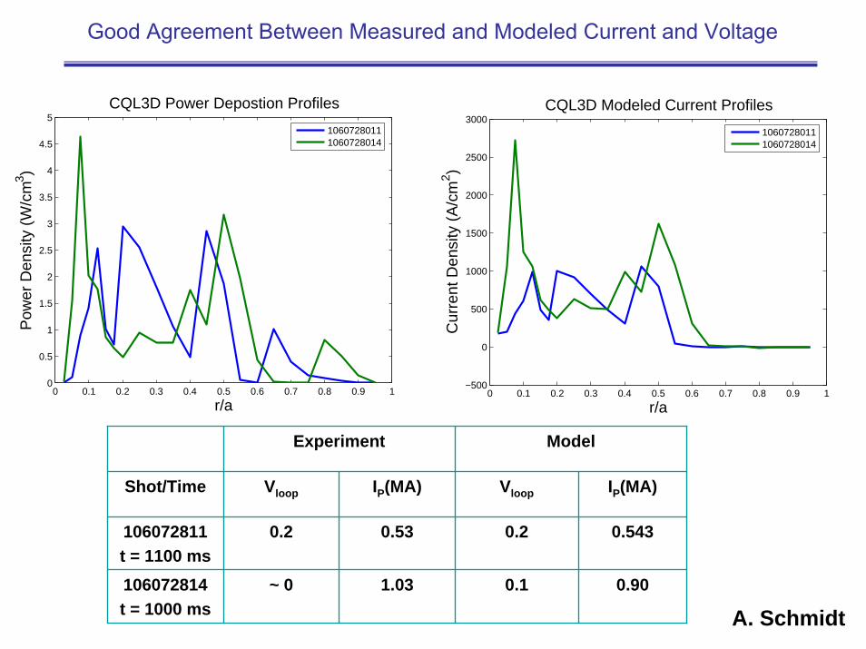
Two Shots Have Been Modeled with GENRAY and CQL3D
Time (sec) Time (sec)
Ip (MA)
Vloop (V)
ne (1019 m-3)
Teo (keV)
PLH (kW)
1060728011 1060728014
0 0.1 0.2 0.3 0.4 0.5 0.6 0.7 0.8 0.9 10
0.5
1
1.5
2
2.5
3
3.5
4
4.5
5
r/a
Pow
er D
ensi
ty (
W/c
m3 )
CQL3D Power Depostion Profiles
10607280111060728014
0 0.1 0.2 0.3 0.4 0.5 0.6 0.7 0.8 0.9 1−500
0
500
1000
1500
2000
2500
3000
r/a
Cur
rent
Den
sity
(A
/cm
2 )
CQL3D Modeled Current Profiles
10607280111060728014
Experiment Model
Shot/Time Vloop IP(MA) Vloop IP(MA)
106072811t = 1100 ms
0.2 0.53 0.2 0.543
106072814t = 1000 ms
~ 0 1.03 0.1 0.90
Good Agreement Between Measured and Modeled Current and Voltage
A. Schmidt
5 10 15 20 25 300
2
4
6
8
10
12
14
16
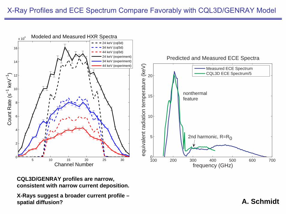
x 104 Modeled and Measured HXR Spectra
Channel Number
Cou
nt R
ate
(s−
1 keV
−1 )
24 keV (cql3d)34 keV (cql3d)44 keV (cql3d)24 keV (experiment)34 keV (experiment)44 keV (experiment)
X-Ray Profiles and ECE Spectrum Compare Favorably with CQL3D/GENRAY Model
CQL3D/GENRAY profiles are narrow, consistent with narrow current deposition.
X-Rays suggest a broader current profile –spatial diffusion? A. Schmidt
100 200 300 400 500 600 7000
5
10
15
20
Predicted and Measured ECE Spectra
frequency (GHz)
equi
vale
nt r
adia
tion
tem
pera
ture
(ke
V)
nonthermalfeature
2nd harmonic, R=R0
Measured ECE SpectrumCQL3D ECE Spectrum/5
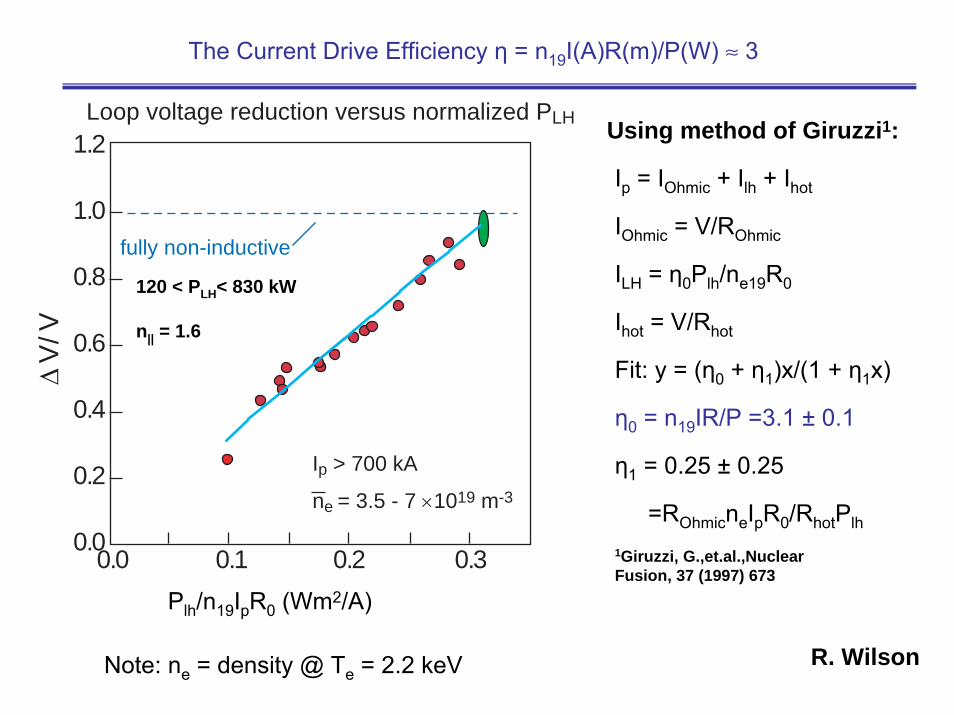
The Current Drive Efficiency η = n19I(A)R(m)/P(W) ≈ 3
Ip = IOhmic + Ilh + Ihot
IOhmic = V/ROhmic
ILH = η0Plh/ne19R0
Ihot = V/Rhot
Fit: y = (η0 + η1)x/(1 + η1x)
η0 = n19IR/P =3.1 ± 0.1
η1 = 0.25 ± 0.25
=ROhmicneIpR0/RhotPlh
1Giruzzi, G.,et.al.,NuclearFusion, 37 (1997) 673
R. Wilson
Using method of Giruzzi1:
Note: ne = density @ Te = 2.2 keV
0.0
0.2
0.4
0.6
0.8
1.0
1.2
0.0 0.1 0.2 0.3
Δ V
/ V
PLH / ne Ip Ro (w m2 / 1019 A)
Loop voltage reduction versus normalized PLH
fully non-inductive
Ip > 700 kA
ne = 3.5 - 7 ×10¹⁹ m-3
120 < PLH< 830 kW
n|| = 1.6
Plh/n19IpR0 (Wm2/A)
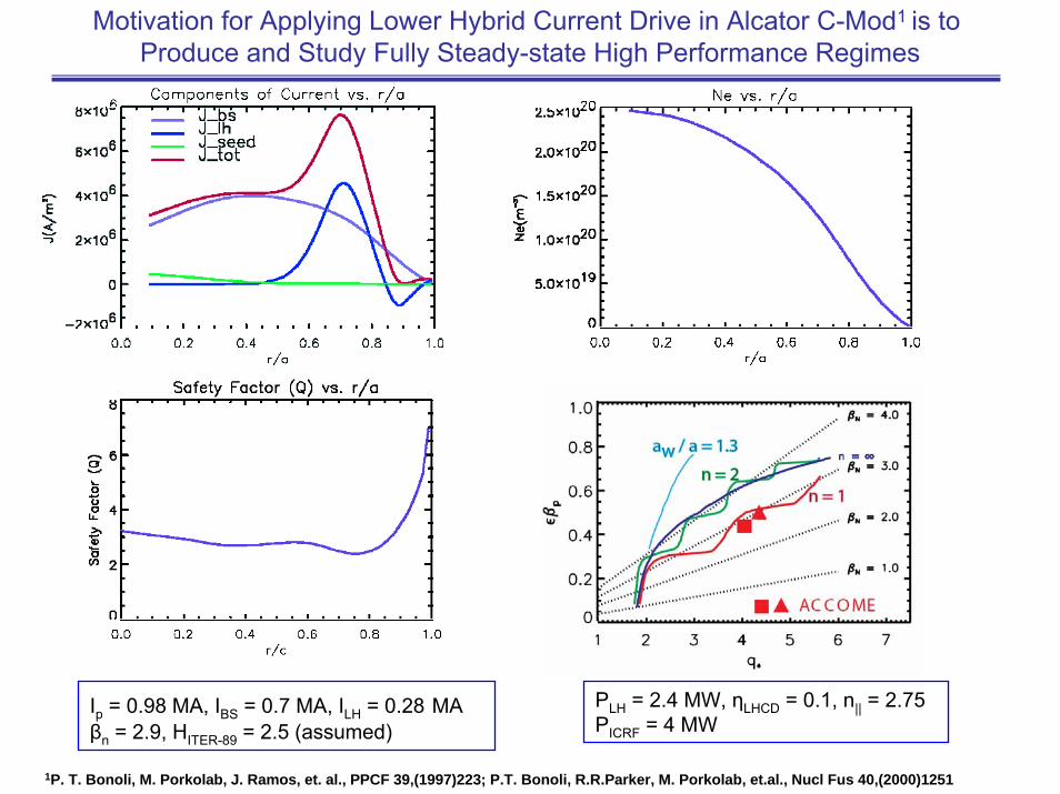
Motivation for Applying Lower Hybrid Current Drive in Alcator C-Mod1 is to Produce and Study Fully Steady-state High Performance Regimes
Ip = 0.98 MA, IBS = 0.7 MA, ILH = 0.28 MAβn = 2.9, HITER-89 = 2.5 (assumed)
PLH = 2.4 MW, ηLHCD = 0.1, n|| = 2.75 PICRF = 4 MW
1P. T. Bonoli, M. Porkolab, J. Ramos, et. al., PPCF 39,(1997)223; P.T. Bonoli, R.R.Parker, M. Porkolab, et.al., Nucl Fus 40,(2000)1251
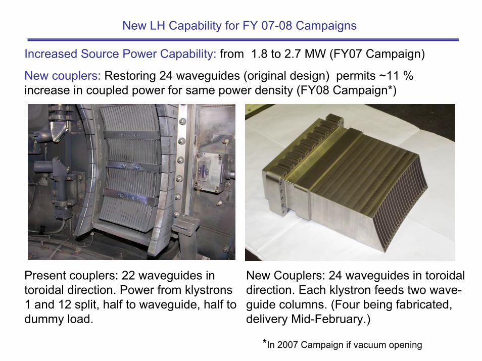
Increased Source Power Capability: from 1.8 to 2.7 MW (FY07 Campaign)
New couplers: Restoring 24 waveguides (original design) permits ~11 % increase in coupled power for same power density (FY08 Campaign*)
New Couplers: 24 waveguides in toroidaldirection. Each klystron feeds two wave-guide columns. (Four being fabricated, delivery Mid-February.)
Present couplers: 22 waveguides intoroidal direction. Power from klystrons1 and 12 split, half to waveguide, half todummy load.
New LH Capability for FY 07-08 Campaigns
*In 2007 Campaign if vacuum opening
The overall goal for next campaigns is to develop LHCD into a tool that can be used to control and optimize plasma preformance. Specific objectives include:
Lower Hybrid Experimental Objectives for FY 07-08 Campaigns
Achieve Vloop = 0 for ~ 0.5 s (several resistive diffusion times).Demonstrate dI/dt > 0 with dΦtrans /dt=0 and evaluate efficiency of transformerless startup, compare with Fisch-Karney theory.
Explore parametric dependence (n, T, n||,BT, Zeff) of efficiency and compare with theory (Fisch-Karney) and modeling (CQL3Dand GENRAY)
Compare in detail X-Ray and ECE emissions with GENRAY and CQL3D and DKE FP models
Optimize coupling in L-Mode, ICRF-heated and H-mode plasmasand develop improved coupling model
Operate at high power and drive significant current in H-Modetarget discharge
Simulate alpha particle absorption of LH waves on ICRFgenerated proton tail
Measure current profile modification – MSE and/or Polarimetry
Begin using LHCD as tool to access AT modes – see Amanda’s talk.
Lower Hybrid Experimental Objectives for FY 07-08 Campaigns (Cont’d)
Results from the FY07-08 campaigns will be invaluable in informing theLHCD decision for ITER
Lower Hybrid Upgrade Plans (Phase II)
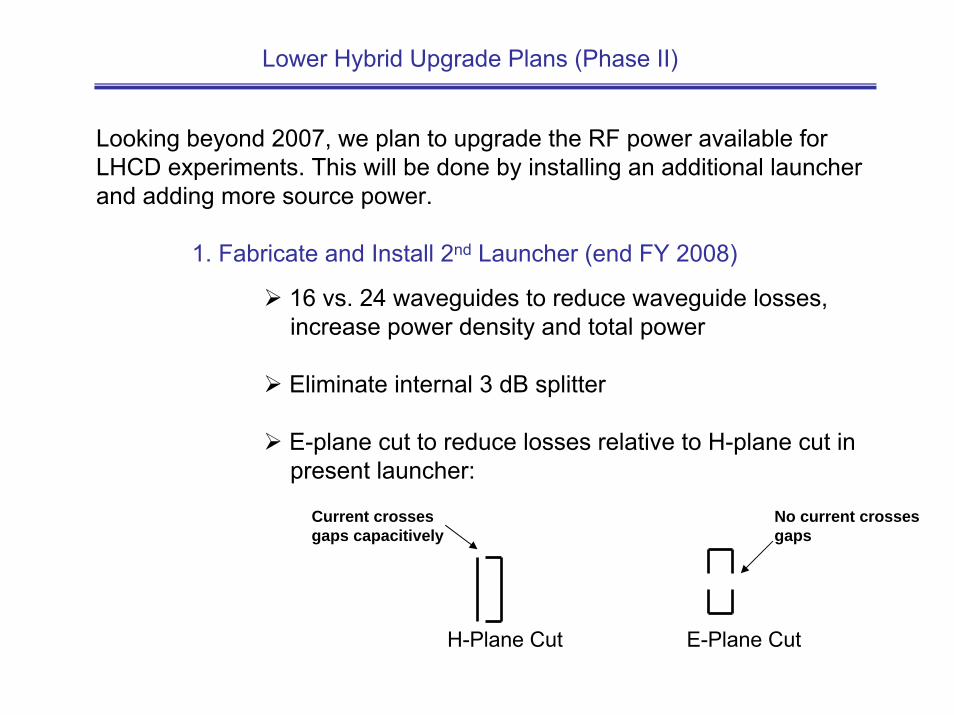
Looking beyond 2007, we plan to upgrade the RF power available for LHCD experiments. This will be done by installing an additional launcher and adding more source power.
1. Fabricate and Install 2nd Launcher (end FY 2008)
H-Plane Cut
Current crosses gaps capacitively
E-Plane Cut
No current crossesgaps
16 vs. 24 waveguides to reduce waveguide losses, increase power density and total power
Eliminate internal 3 dB splitter
E-plane cut to reduce losses relative to H-plane cut in present launcher:
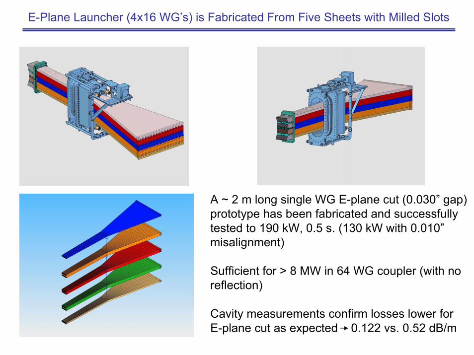
E-Plane Launcher (4x16 WG’s) is Fabricated From Five Sheets with Milled Slots
A ~ 2 m long single WG E-plane cut (0.030” gap) prototype has been fabricated and successfully tested to 190 kW, 0.5 s. (130 kW with 0.010” misalignment)
Sufficient for > 8 MW in 64 WG coupler (with no reflection)
Cavity measurements confirm losses lower forE-plane cut as expected 0.122 vs. 0.52 dB/m
Longer Term Plans (Cont’d)
2. Add more source power:
Reference plan:
Regun 4 remaining klystrons from Alcator C experiment and restore to 250 kW CW nominal operation (2007-2008)
Refurbish 4th cart (filament and magnet power supplies, vacuum pumps, circulators, controls, etc.) and install in C- Mod cell (2008)
Design and Fabricate splitter network (2007-2008)
Replumb waveguides – 8 klystrons (2 MW) feeding eachlauncher (2009)
Begin LH experiments with 2 launchers and 4 MW source power (2009)
Longer Term Plans (Cont’d)
2. Add more source power:
Aggressive plan (requiring incremental funding):
Same as reference plan (except for replumbingwaveguides), but in addition:
Purchase 4 new klystrons (2008-2009)
Fabricate 5th cart and install in C-Mod Cell (2010)
Begin LH experiments with 2 launchers and 5 MW source power (2010)
The incremental cost of the aggressive plan is ~ 3 M$
Summary and Conclusions (1)
Lower Hybrid Current Drive has been implemented on Alcator C-Mod:
Goal is to use LHCD as a tool to supplement bootstrap current and enable performance optimization studies leading to attractive steady-state regimes.
Results will inform LHCD decision for ITER
Nearly 1 MW has been coupled and current drive approaching 1 MA at n ~ 5e19 m-3
has been achieved.
First results indicate current drive efficiency is in line with expectations based onmodels and sufficient to achieve target regimes, although higher n|| (lower efficiency) for accessibility and additional power will be required at higher density.
Good general agreement achieved between experiment and both X-Ray and ECE CQL3D/GENRAY synthetic diagnostics. There are indications that j(r) is broader than code predicts – supported by TRANSP modeling.
Summary and Conclusions (2)
In next Alcator C-Mod campaigns, emphasis will be on raising absorbed power toward 1.5 MW, increasing density above ne = 1e20 m-3 , exploring interactions with ICRH antenna, coupling into H-Mode plasmas and using as tool to access AT regimes.
Meanwhile, a second phase incorporating a second launcher and upgrading the source power to 4 MW is underway – operation scheduled for 2009.
In a more aggressive plan requiring incremental funding, the source power would increased to 5 MW in 2010 – this would provide margin for optimizing steady-state AT modes.