
Local Target Cross Sections in Optical Band - wseas.us · PDF fileLocal Target Cross Sections...
3
Local Target Cross Sections in Optical Band OTAKAR WILFERT, ALEŠ PROKEŠ Institute of Radio Electronics, Brno University of Technology, Purkyňova 118, 612 00 Brno, CZECH REPUBLIC Abstract: Paper deals with a mono-static experimental system for measuring of the local relative target cross sections (LRTCS) in optical band λ = 1.06 µm by using YAG: Nd 3+ laser. Requirements analysis of the optical receiver is presented. The way of the LRTCS measuring and their distribution on the airplane surface at the distance of 200 m from laser transmitter is shown. Key-Words: relative cross section, reflectivity, optical receiver, avalanche photodiode, neodymium laser 1 Introduction Clarification of the LRTCS and its definition is presented in [1, 2], where the difference between the target cross section used in microwave radar system and the target cross section used in laser radar system is also emphasized. The aim of this paper is to introduce readers to the methodology of the LRTCS experimental determination and to the experimental measuring system that was used. The term “local” means that the target (in our case the military training airplane) intercepts the entire beam and therefore as an extended target is classified [3]. Measuring of the relative value of the local target cross section is preferred to the measuring of absolute value one due to its easier determination. It is assumed that in case of an extended target the beam cross section at the target position is much smaller than the total target projection to the plane perpendicular to the direction of irradiation. For this reason the LRTCS is used with definition given by i i bs σ σ σ ′= , (1) where σ i is the absolute local cross section of the target (airplane) and σ bs is the absolute cross section of the reference surface (bead screen) placed perpendicularly to the laser beam at the same distance as the target and irradiated with the identical intensity. When the optical receiver works at the linear region of the transition characteristic, (1) can be expressed as , R i i Rbs v v σ ′= , (2) where v R,i and v Rbs are voltage levels of received signals from target and reference surface respectively. 2 Description of Measuring Chain Measuring equipment has been composed of the optical transmitter, beam splitter, target, optical receiver and two-channel storage oscilloscope as shown in Fig. 1. The total measuring chain creates so-called mono-static system. The optical transmitter consists of the neodymium laser (YAG:Nd 3+ ) and optical system (transmitted aperture diameter of 30 mm). The laser works in the pulse mode (pulse width of τ P = 20 ns). OT BS OR v M v R SO A B MT Fig. 1 Measuring chain (mono-static system) (OT – optical transmitter, BS – beam splitter, MT – measuring target, OR – optical receiver, SO – storage oscilloscope) The energy of laser radiation has been checked by using auxiliary monitoring system shown in Fig. 2. It is assembled from the beam splitter, PIN photodiode and high impedance amplifier. Output voltage v M is measured by the storage oscilloscope and used for triggering. Divergence of the laser beam is θ L = 1 mrad and average pulse energy is E L = 23,4 ± 2% mJ. 3 Analysis of the Optical Receiver Performance Optical receiver shown in Fig. 3 consists of the receiver branch and eye branch. Photocurrent of the avalanche photodiode (APD) is amplified and converted to the voltage v R in the transimpedance amplifier (TIA). Proceedings of the 5th WSEAS Int. Conf. on Signal Processing, Computational Geometry & Artificial Vision, Malta, September 15-17, 2005 (pp244-246)
Transcript of Local Target Cross Sections in Optical Band - wseas.us · PDF fileLocal Target Cross Sections...
Local Target Cross Sections in Optical Band
OTAKAR WILFERT, ALEŠ PROKEŠ Institute of Radio Electronics,
Brno University of Technology, Purkyňova 118, 612 00 Brno, CZECH REPUBLIC
Abstract: Paper deals with a mono-static experimental system for measuring of the local relative target cross sections (LRTCS) in optical band λ = 1.06 µm by using YAG: Nd3+ laser. Requirements analysis of the optical receiver is presented. The way of the LRTCS measuring and their distribution on the airplane surface at the distance of 200 m from laser transmitter is shown.
Key-Words: relative cross section, reflectivity, optical receiver, avalanche photodiode, neodymium laser
1 Introduction Clarification of the LRTCS and its definition is presented in [1, 2], where the difference between the target cross section used in microwave radar system and the target cross section used in laser radar system is also emphasized.
The aim of this paper is to introduce readers to the methodology of the LRTCS experimental determination and to the experimental measuring system that was used. The term “local” means that the target (in our case the military training airplane) intercepts the entire beam and therefore as an extended target is classified [3].
Measuring of the relative value of the local target cross section is preferred to the measuring of absolute value one due to its easier determination.
It is assumed that in case of an extended target the beam cross section at the target position is much smaller than the total target projection to the plane perpendicular to the direction of irradiation. For this reason the LRTCS is used with definition given by
ii
bs
σσσ
′ = , (1)
where σi is the absolute local cross section of the target (airplane) and σbs is the absolute cross section of the reference surface (bead screen) placed perpendicularly to the laser beam at the same distance as the target and irradiated with the identical intensity.
When the optical receiver works at the linear region of the transition characteristic, (1) can be expressed as
,R ii
Rbs
vv
σ ′ = , (2)
where vR,i and vRbs are voltage levels of received signals from target and reference surface respectively.
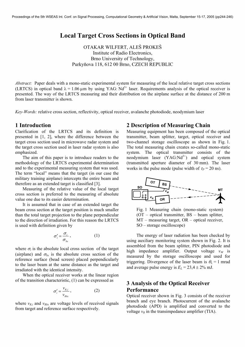
2 Description of Measuring Chain Measuring equipment has been composed of the optical transmitter, beam splitter, target, optical receiver and two-channel storage oscilloscope as shown in Fig. 1. The total measuring chain creates so-called mono-static system. The optical transmitter consists of the neodymium laser (YAG:Nd3+) and optical system (transmitted aperture diameter of 30 mm). The laser works in the pulse mode (pulse width of τP = 20 ns).
OT BS
OR
vMvR
SO
A B
MT
Fig. 1 Measuring chain (mono-static system) (OT – optical transmitter, BS – beam splitter, MT – measuring target, OR – optical receiver, SO – storage oscilloscope)
The energy of laser radiation has been checked by using auxiliary monitoring system shown in Fig. 2. It is assembled from the beam splitter, PIN photodiode and high impedance amplifier. Output voltage vM is measured by the storage oscilloscope and used for triggering. Divergence of the laser beam is θL = 1 mrad and average pulse energy is EL = 23,4 ± 2% mJ.
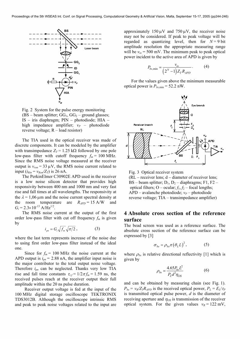
3 Analysis of the Optical Receiver Performance Optical receiver shown in Fig. 3 consists of the receiver branch and eye branch. Photocurrent of the avalanche photodiode (APD) is amplified and converted to the voltage vR in the transimpedance amplifier (TIA).
Proceedings of the 5th WSEAS Int. Conf. on Signal Processing, Computational Geometry & Artificial Vision, Malta, September 15-17, 2005 (pp244-246)
PINHIA
GG2
ID
BS
RvP
vM
GG1
Laser beam
Fig. 2 System for the pulse energy monitoring (BS – beam splitter; GG1, GG2 – ground glasses; IS – iris diaphragm; PIN – photodiode; HIA – high impedance amplifier; vP – photodiode reverse voltage; R – load resistor)
The TIA used in the optical receiver was made of discrete components. It can be modeled by the amplifier with transimpedance ZT = 1.25 kΩ followed by one pole low-pass filter with cutoff frequency fm = 100 MHz. Since the RMS noise voltage measured at the receiver output is vron = 33 µV, the RMS noise current related to input (iRin = vRon/ZT) is 26 nA.
The PerkinElmer C30902E APD used in the receiver is a low noise silicon detector that provides high responsivity between 400 nm and 1000 nm and very fast rise and fall times at all wavelengths. The responsivity at the λ = 1,06 µm and the noise current spectral density at the room temperature are RAPD = 15 A/W and Gi = 2.3×10⁻¹³ A/Hz1/2.
The RMS noise current at the output of the first order low-pass filter with cut off frequency fm is given by 2πmipn fGi = , (3)
where the last term represents increase of the noise due to using first order low-pass filter instead of the ideal one.
Since for fm = 100 MHz the noise current at the APD output is ipn = 2.88 nA, the amplifier input noise is the major contributor to the total output noise voltage. Therefore ipn can be neglected. Thanks very low TIA rise and fall time constants τr,f = 1/2π fm = 1.59 ns, the received pulses reach at the receiver output their full amplitude within the 20 ns pulse duration.
Receiver output voltage is fed at the input of the 100 MHz digital storage oscilloscope TEKTRONIX TDS3012B. Although the oscilloscope intrinsic RMS and peak to peak noise voltages related to the input are
approximately 150 µV and 750 µV, the receiver noise may not be considered. If peak to peak voltage will be regarded as quantizing level, then for N = 9 bit amplitude resolution the appropriate measuring range will be vio = 500 mV. The minimum peak to peak optical power incident to the active area of APD is given by
( ),min2 1
iobs N
T APD
vPZ R
=−
. (4)
For the values given above the minimum measurable optical power is Pbs,min = 52.2 nW.
Fig. 3 Optical receiver system (RL – receiver lens; d – diameter of receiver lens; BS – beam splitter; D1, D2 – diaphragms; F1, F2 – optical filters; O – ocular; f1, f2 – focal lengths; APD – avalanche photodiode; vP – photodiode reverse voltage; TIA – transimpedance amplifier)
4 Absolute cross section of the reference surface The bead screen was used as a reference surface. The absolute cross section of the reference surface can be expressed by [3]
, (5) ( )2bs bs L Lσ ρ π θ=
where ρbs is relative directional reflectivity [1] which is given by
2
24.65 bs
bsL OS
P LP d
ρη
= (6)
and can be obtained by measuring chain (see Fig. 1). Pbs = vR/ZTRAPD is the received optical power, PL = EL/τP is transmitted optical pulse power, d is the diameter of receiving aperture and ηOS is transmission of the receiver optical system. For the given values vR = 122 mV,
Proceedings of the 5th WSEAS Int. Conf. on Signal Processing, Computational Geometry & Artificial Vision, Malta, September 15-17, 2005 (pp244-246)
ηOS = 0.73 and d = 70 mm the relative directional reflectivity ρbs = 2.06 and absolute cross section of the reference surface σbs = 0.327 m2 were calculated.
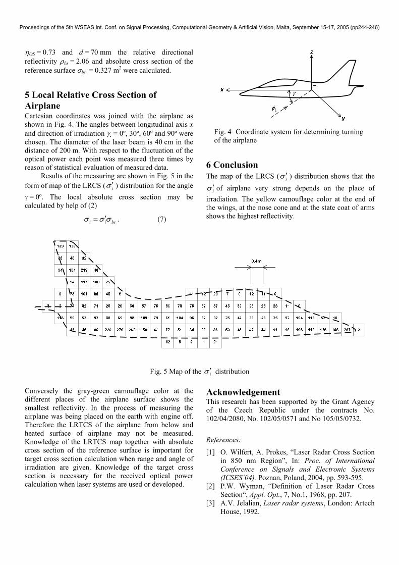
5 Local Relative Cross Section of Airplane Cartesian coordinates was joined with the airplane as shown in Fig. 4. The angles between longitudinal axis x and direction of irradiation γ = 0º, 30º, 60º and 90º were chosen . The diameter of the laser beam is 40 cm in the distance of 200 m. With respect to the fluctuation of the optical power each point was measured three times by reason of statistical evaluation of measured data.
Results of the measuring are shown in Fig. 5 in the form of map of the LRCS ( iσ ′ ) distribution for the angle γ = 0º. The local absolute cross section may be calculated by help of (2)
i i bsσ σ σ′= . (7)
Fig. 4 Coordinate system for determining turning of the airplane
6 Conclusion The map of the LRCS ( iσ ′ ) distribution shows that the
iσ ′ of airplane very strong depends on the place of irradiation. The yellow camouflage color at the end of the wings, at the nose cone and at the state coat of arms shows the highest reflectivity.
Fig. 5 Map of the iσ ′ distribution
Conversely the gray-green camouflage color at the different places of the airplane surface shows the smallest reflectivity. In the process of measuring the airplane was being placed on the earth with engine off. Therefore the LRTCS of the airplane from below and heated surface of airplane may not be measured. Knowledge of the LRTCS map together with absolute cross section of the reference surface is important for target cross section calculation when range and angle of irradiation are given. Knowledge of the target cross section is necessary for the received optical power calculation when laser systems are used or developed.
Acknowledgement This research has been supported by the Grant Agency of the Czech Republic under the contracts No. 102/04/2080, No. 102/05/0571 and No 105/05/0732.
References:
[1] O. Wilfert, A. Prokes, “Laser Radar Cross Section in 850 nm Region”, In: Proc. of International Conference on Signals and Electronic Systems (ICSES´04). Poznan, Poland, 2004, pp. 593-595.
[2] P.W. Wyman, “Definition of Laser Radar Cross Section“, Appl. Opt., 7, No.1, 1968, pp. 207.
[3] A.V. Jelalian, Laser radar systems, London: Artech House, 1992.
Proceedings of the 5th WSEAS Int. Conf. on Signal Processing, Computational Geometry & Artificial Vision, Malta, September 15-17, 2005 (pp244-246)