Lightning Protection for Mobile Phone Base Stations by ...
7
Lightning Protection for Mobile Phone Base Stations by combining λ/4 short Stub and λ/4 open Stub CHIKASHI OKABAYASHI, HITOSHI KIJIMA Sankosha Corporation, Tokaigakuin University JAPAN Abstract: This paper describes lightning protection for mobile phone base stations by combining quarter wave short and open stubs. MPBS (Mobile Phone Base Stations) have antenna towers and are often installed on the top of mountains. Therefore they have a high probability of lightning strikes.The most important lightning protection system is a bonding network and an earth system. All incoming services should be bonded at the entry to the MPBS in order to obtain an equipotential environment for all systems. And SPD (Surge Protective Device) should be installed at the entry to the BTS ( Base Transceiver Station ) . As an SPD, either a GDT or λ/4 short stub was used. However, conventional SPD such as a GDT and λ/4 short stub cannot completely prevent the lightning surge current diverging to the BTS side. Therefore we have developed an insulated coaxial SPD that allows lightning surges to be discharged to the ground while passing signals without loss by combining the λ/4 short stub and the λ/4 open stub. The performances of this newly developed product were as follows. Insertion loss was less than 0.1dB, VSWR was less than 1.15 and voltage protection Level Up was 80V. Key-Words:, Mobile Phone Base Stations, Surge Protective Device, λ/4 short stub, λ/4 open stub Received: August 4, 20, 2020. Revised: November 30, 2020. Accepted: December 17, 2020. Published: December 31, 2020. 1 Introduction EMC technologies have been introduced in the articles [1]-[14]. One of EMC technologies to be considered is lighting protection for MPBS (Mobile Phone Base Stations). MPBS have antenna towers and are often installed on the top of mountains. Therefore they have a high probability of lightning strikes. Recommendation ITU-T K.56 provides lighting protection procedures for equipment and cables installed at MPBS[15]. The most important lightning protection system is a bonding network and an earth system. And also, the outer conductor of coaxial cables was bonded to the metallic tower through the antenna hardware. All incoming services should be bonded at the entry to the MPBS in order to obtain an equipotential environment for all systems [15]-[20]. And SPD (Surge Protective Device) should be installed at the entry to the BTS (Base Transceiver Station) [21]. As an SPD, either a GDT or λ/4 short stub was used. However, both a GDT and λ/4 short stub cannot completely prevent the lightning surge current diverging to the BTS side. Therefore we have developed an insulated coaxial SPD that allows lightning surges to be discharged to the ground while passing signals without loss by combining the λ/4 short stub and the λ/4 open stub. The performances of this newly developed product were as follows. (1)Available frequency is 2GHz. (2) Insertion loss was less than 0.1dB. (3) Inter-Modulation Distortion was 160dBc. (4) VSWR was less than 1.15. (5) Voltage Protection Level Up was 80V. (6) Impulse withstand voltage was 30kV (1.2/50μs). 2 Risk analysis on mobile phone base stations Fig.1 shows IKL which is annual thunderstorm days in Japan [22]. Fig.1 IKL ( Annual thunderstorm days) in Japan Recommendation ITU-T K.56 provides lighting protection procedures for equipment and cables installed at MPBS (Mobile Phone Base Station). The frequency of lightning strikes to the tower of MPBS is given by Fa=9cπHt 2 Ng (times/station/year) (1) where:Ng = ground flash density (0.1×IKL), WSEAS TRANSACTIONS on COMMUNICATIONS DOI: 10.37394/23204.2020.19.29 Chikashi Okabayashi, Hitoshi Kijima E-ISSN: 2224-2864 249 Volume 19, 2020
Transcript of Lightning Protection for Mobile Phone Base Stations by ...
Lightning Protection for Mobile Phone Base Stations by combining λ/4
short Stub and λ/4 open Stub
CHIKASHI OKABAYASHI, HITOSHI KIJIMA Sankosha Corporation, Tokaigakuin University
JAPAN
Abstract: This paper describes lightning protection for mobile phone base stations by combining quarter wave short and open stubs. MPBS (Mobile Phone Base Stations) have antenna towers and are often installed on the top of mountains. Therefore they have a high probability of lightning strikes.The most important lightning protection system is a bonding network and an earth system. All incoming services should be bonded at the entry to the MPBS in order to obtain an equipotential environment for all systems. And SPD (Surge Protective Device) should be installed at the entry to the BTS(
Base Transceiver Station). As an SPD, either a GDT or λ/4 short stub was used. However, conventional SPD such as a GDT and λ/4 short stub cannot completely prevent the lightning surge current diverging to the BTS side. Therefore we have developed an insulated coaxial SPD that allows lightning surges to be discharged to the ground while passing signals without loss by combining the λ/4 short stub and the λ/4 open stub. The performances of this newly developed product were as follows.
Insertion loss was less than 0.1dB, VSWR was less than 1.15 and voltage protection Level Up was 80V.
Key-Words:, Mobile Phone Base Stations, Surge Protective Device, λ/4 short stub, λ/4 open stub
Received: August 4, 20, 2020. Revised: November 30, 2020. Accepted: December 17, 2020. Published: December 31, 2020.
1 Introduction EMC technologies have been introduced in the articles
[1]-[14]. One of EMC technologies to be considered is lighting protection for MPBS (Mobile Phone Base Stations). MPBS have antenna towers and are often installed on the top of mountains. Therefore they have a high probability of lightning strikes.
Recommendation ITU-T K.56 provides lighting protection procedures for equipment and cables installed at MPBS[15]. The most important lightning protection system is a bonding network and an earth system. And also, the outer conductor of coaxial cables was bonded to the metallic tower through the antenna hardware. All incoming services should be bonded at the entry to the MPBS in order to obtain an equipotential environment for all systems [15]-[20]. And SPD (Surge Protective Device) should be installed at the entry to the BTS(Base Transceiver Station)[21]. As an SPD, either a GDT or λ/4 short stub was used.
However, both a GDT and λ/4 short stub cannot completely prevent the lightning surge current diverging to the BTS side. Therefore we have developed an insulated coaxial SPD that allows lightning surges to be discharged to the ground while passing signals without loss by combining the λ/4 short stub and the λ/4 open stub. The performances of this newly developed product were as follows.
(1)Available frequency is 2GHz. (2) Insertion loss was less than 0.1dB. (3) Inter-Modulation Distortion was 160dBc. (4) VSWR was less than 1.15. (5) Voltage Protection Level Up was 80V. (6) Impulse withstand voltage was 30kV (1.2/50μs).
2 Risk analysis on mobile phone base
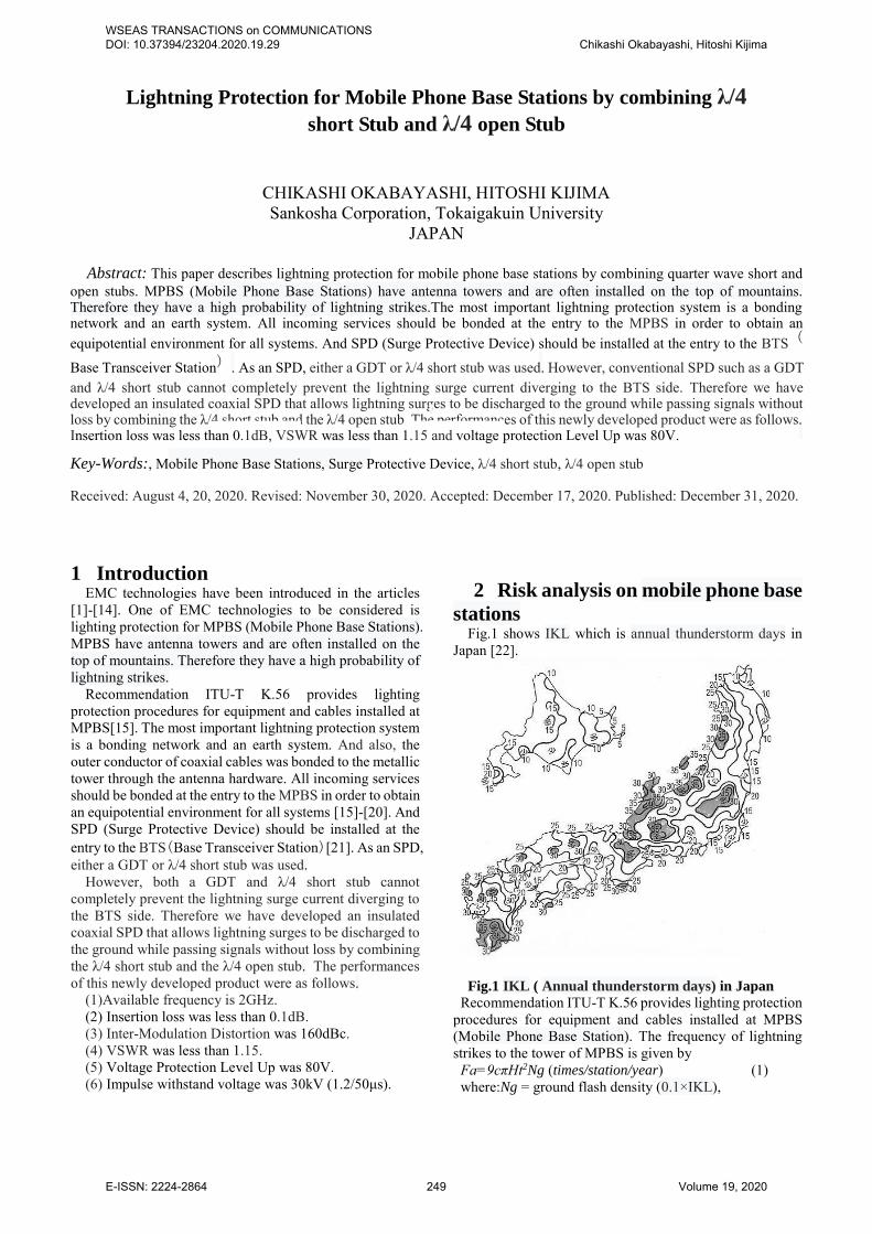
stations Fig.1 shows IKL which is annual thunderstorm days in
Japan [22].
Fig.1 IKL ( Annual thunderstorm days) in Japan
Recommendation ITU-T K.56 provides lighting protection procedures for equipment and cables installed at MPBS (Mobile Phone Base Station). The frequency of lightning strikes to the tower of MPBS is given by
Fa=9cπHt2Ng (times/station/year) (1) where:Ng = ground flash density (0.1×IKL),
WSEAS TRANSACTIONS on COMMUNICATIONS DOI: 10.37394/23204.2020.19.29 Chikashi Okabayashi, Hitoshi Kijima
E-ISSN: 2224-2864 249 Volume 19, 2020
Ht = tower height (km), c = exposure factor (c = 1 for flat ground, c = 2 for
mountain top) . Assuming Japanese typical condition that the tower height
is 36 m located at mountain top and IKL is 30 days a year, the lightning strike frequency Fa is calculated as follows.
Fa=9×2×3.14×0.0362×3=0.22 (2) In other words, MPBS installed on the mountain top are
subject to lightning strikes once every 4.5 years (1/0.22 =4.5 ) in Japan.
3 Lightning protection measures for
MPBS and its lightning surge current
injecting test using existing MPBS
3.1 Lightning protection measures for
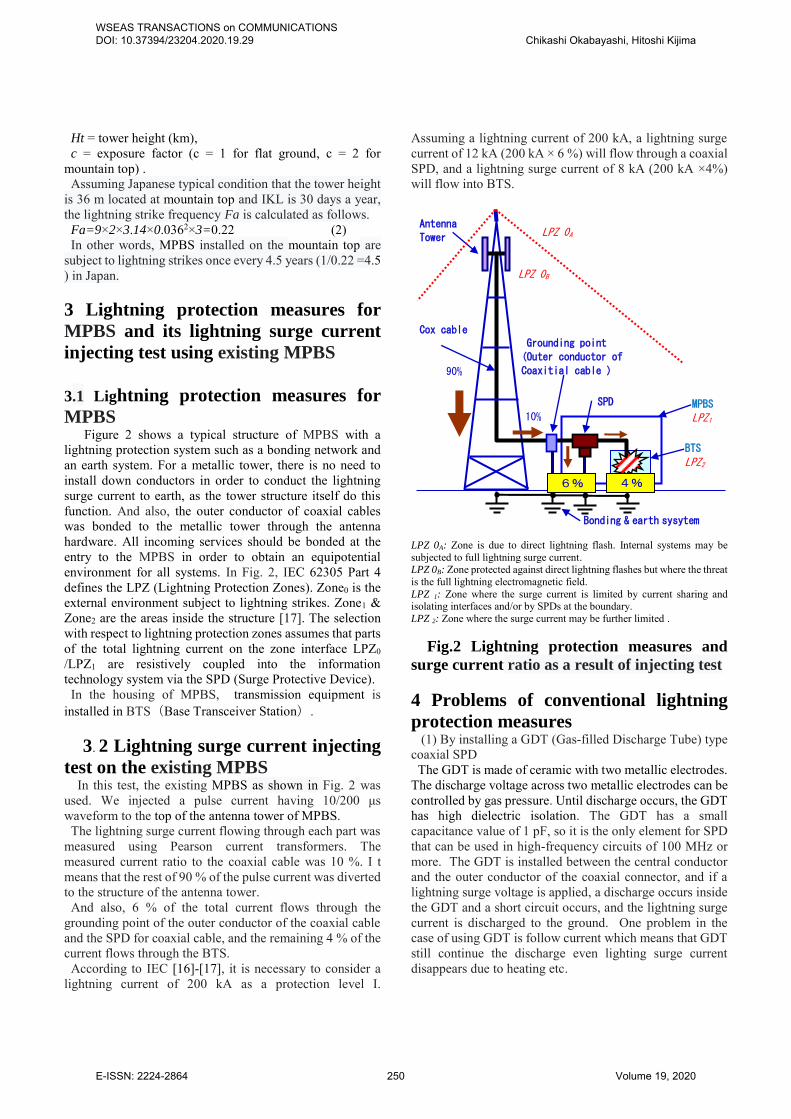
MPBS Figure 2 shows a typical structure of MPBS with a
lightning protection system such as a bonding network and an earth system. For a metallic tower, there is no need to install down conductors in order to conduct the lightning surge current to earth, as the tower structure itself do this function. And also, the outer conductor of coaxial cables was bonded to the metallic tower through the antenna hardware. All incoming services should be bonded at the entry to the MPBS in order to obtain an equipotential environment for all systems. In Fig. 2, IEC 62305 Part 4 defines the LPZ (Lightning Protection Zones). Zone0 is the external environment subject to lightning strikes. Zone1 & Zone2 are the areas inside the structure [17]. The selection with respect to lightning protection zones assumes that parts of the total lightning current on the zone interface LPZ0 /LPZ1 are resistively coupled into the information technology system via the SPD (Surge Protective Device).
In the housing of MPBS, transmission equipment is installed in BTS(Base Transceiver Station).
3. 2 Lightning surge current injecting
test on the existing MPBS In this test, the existing MPBS as shown in Fig. 2 was
used. We injected a pulse current having 10/200 μs waveform to the top of the antenna tower of MPBS.
The lightning surge current flowing through each part was measured using Pearson current transformers. The measured current ratio to the coaxial cable was 10 %. I t means that the rest of 90 % of the pulse current was diverted to the structure of the antenna tower.
And also, 6 % of the total current flows through the grounding point of the outer conductor of the coaxial cable and the SPD for coaxial cable, and the remaining 4 % of the current flows through the BTS.
According to IEC [16]-[17], it is necessary to consider a lightning current of 200 kA as a protection level I.
Assuming a lightning current of 200 kA, a lightning surge current of 12 kA (200 kA × 6 %) will flow through a coaxial SPD, and a lightning surge current of 8 kA (200 kA ×4%) will flow into BTS.
LPZ 0A: Zone is due to direct lightning flash. Internal systems may be subjected to full lightning surge current. LPZ 0B: Zone protected against direct lightning flashes but where the threat is the full lightning electromagnetic field. LPZ 1: Zone where the surge current is limited by current sharing and isolating interfaces and/or by SPDs at the boundary. LPZ 2: Zone where the surge current may be further limited .
Fig.2 Lightning protection measures and
surge current ratio as a result of injecting test
4 Problems of conventional lightning
protection measures (1) By installing a GDT (Gas-filled Discharge Tube) type
coaxial SPD The GDT is made of ceramic with two metallic electrodes.
The discharge voltage across two metallic electrodes can be controlled by gas pressure. Until discharge occurs, the GDT has high dielectric isolation. The GDT has a small capacitance value of 1 pF, so it is the only element for SPD that can be used in high-frequency circuits of 100 MHz or more. The GDT is installed between the central conductor and the outer conductor of the coaxial connector, and if a lightning surge voltage is applied, a discharge occurs inside the GDT and a short circuit occurs, and the lightning surge current is discharged to the ground. One problem in the case of using GDT is follow current which means that GDT still continue the discharge even lighting surge current disappears due to heating etc.
BTS
LPZ2
LPZ 0A
LPZ 0B
MPBS
LPZ1
Antenna
Tower
tower
Grounding point
(Outer conductor of
Coaxitial cable )
SPD
Bonding & earth sysytem
Cox cable
90%
6% 4%
10%
WSEAS TRANSACTIONS on COMMUNICATIONS DOI: 10.37394/23204.2020.19.29 Chikashi Okabayashi, Hitoshi Kijima
E-ISSN: 2224-2864 250 Volume 19, 2020
The appearance of the product manufactured by Sankosha Corporation [23] is shown in Fig.3 and the circuit diagram is shown in Fig.4.
Fig.3 GDT type coaxial SPD
Fig.4 Circuit diagram of GDT type
coaxial SPD
(2) By installing a λ/4 short stub type coaxial SPD A stub is a distributed constant line connected in parallel to
a transmission line. When the line length of this distribution constant is adjusted by the ratio of the signal wavelength λ, it becomes a capacitor or an inductor when viewed from the input end, so it is widely used as a band filter in high-frequency circuits. A short circuit between the central conductor and the outer conductor with a line length of λ/4 is called a λ/4 short stub, and it is also used as a coaxial SPD because of its filter characteristics. Fig. 5 shows the appearance of the product manufactured by Sankosha Corporation.
Fig.5 Appearance of λ/4 short stub
Central conductor
Zi (Ω)
Outer conductor
Fig.6 Model diagram of λ/4 short stub
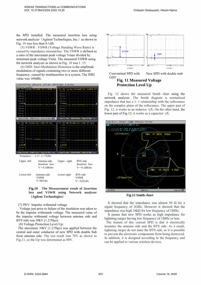
Fig. 6 shows a model diagram of the λ/4 short stub. The input impedance Zin of the λ/4 short stub is given by
the following equation [24]. Zin=+jZ0 tan (2πL/λ) (3) Where,
λ : wavelength (m) L : short-circuit line length (m) Zo : Characteristic impedance (Ω) If L = λ/4, Zo = 50Ω,
Zin=+j50tan(π/2) = +j50×∞= ∞ (Ω)
Therefore, although the central conductor of the λ/4 short stub is grounded, the impedance can be regarded as infinite with respect to the signal frequency f.
On the other hand, taking frequency f / 2, which is half of the signal frequency f, as an example, the short-circuit line length L is λ / 8.
Zin=+j50tan(π/4) = +j50×1= 50 (Ω) That is, the impedance becomes low for a frequency different from the signal frequency f, and a different frequency such as a lightning surge is discharged to the ground.
However, both a GDT and λ/4 short stub cannot completely prevent the lightning surge current from diverging to the BTS side. In other words, as the impedance of the BTS side is extremely low, about 4 % of the total lightning surge current goes around the BTS mentioned above.
In other words, in the case of 200kA lightning surge current, 8 kA current has flowed into the BTS. This 8kA current generates an induced voltage in the internal circuit by electromagnetic induction. It means that lightning damage such as LSIs in BTS was caused by lightning surge current via the coaxial cable. 5. Newly developed coaxial SPD by combining
quarter wave short stub and quarter wave
open stub Another stub is called a λ/4 open stub, and Fig. 7 shows a
model diagram. The input impedance Zin of the λ/4 open stub is given by the following equation [24].
← Antenna BTS→
Central conductor
Outer conductor
GDT
Surge current
λ/4
WSEAS TRANSACTIONS on COMMUNICATIONS DOI: 10.37394/23204.2020.19.29 Chikashi Okabayashi, Hitoshi Kijima
E-ISSN: 2224-2864 251 Volume 19, 2020
Zin=-jZ0 cot (2πL/λ) (4) Where,
λ : wavelength (m) L : short-circuit line length (m) Zo : Characteristic impedance (Ω) If L = λ / 4, Zo = 50Ω,
Zin=-j50cot (π/2) = -j50×0= 0 (Ω) Therefore, the λ/4 open stub can be regarded as lossless for
the signal frequency f. On the other hand, taking the frequency 2f, which is twice
the signal frequency f, as an example, the short-circuit line length L is λ/2.
Zin=-j50cot (π) = -j50×∞= ∞ (Ω)
That is, high impedance is exhibited for a frequency different from the signal frequency f.
Fig.7 Model diagram of λ/4 open stub
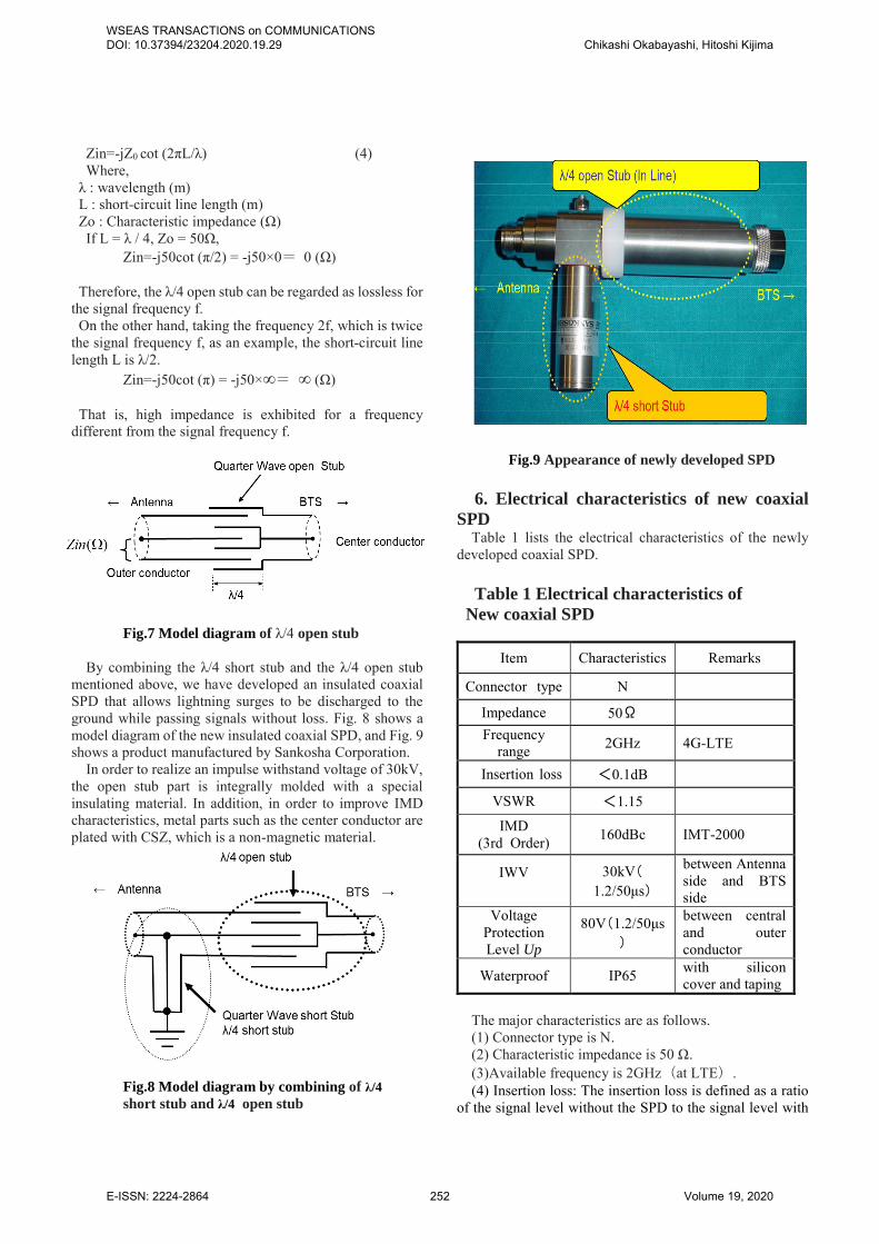
By combining the λ/4 short stub and the λ/4 open stub mentioned above, we have developed an insulated coaxial SPD that allows lightning surges to be discharged to the ground while passing signals without loss. Fig. 8 shows a model diagram of the new insulated coaxial SPD, and Fig. 9 shows a product manufactured by Sankosha Corporation.
In order to realize an impulse withstand voltage of 30kV, the open stub part is integrally molded with a special insulating material. In addition, in order to improve IMD characteristics, metal parts such as the center conductor are plated with CSZ, which is a non-magnetic material.
Fig.8 Model diagram by combining of λ/4
short stub and λ/4 open stub
Fig.9 Appearance of newly developed SPD
6. Electrical characteristics of new coaxial
SPD Table 1 lists the electrical characteristics of the newly
developed coaxial SPD.
Table 1 Electrical characteristics of
New coaxial SPD
Item Characteristics Remarks
Connector type N
Impedance 50Ω Frequency
range 2GHz 4G-LTE
Insertion loss <0.1dB
VSWR <1.15
IMD (3rd Order) 160dBc IMT-2000
IWV
30kV(1.2/50μs)
between Antenna side and BTS side
Voltage Protection Level Up
80V(1.2/50μs)
between central and outer conductor
Waterproof IP65 with silicon cover and taping
The major characteristics are as follows. (1) Connector type is N. (2) Characteristic impedance is 50 Ω. (3)Available frequency is 2GHz(at LTE). (4) Insertion loss: The insertion loss is defined as a ratio
of the signal level without the SPD to the signal level with
WSEAS TRANSACTIONS on COMMUNICATIONS DOI: 10.37394/23204.2020.19.29 Chikashi Okabayashi, Hitoshi Kijima
E-ISSN: 2224-2864 252 Volume 19, 2020
the SPD installed. The measured insertion loss using network analyzer(Agilent Technologies, Inc.)as shown in Fig. 10 was less than 0.1dB.
(5) VSWR : VSWR (Voltage Standing Wave Ratio) is caused by impedance mismatches. The VSWR is defined as a ratio of the maximum peak voltage Vmax divided by minimum peak voltage Vmin. The measured VSWR using the network analyzer as shown in Fig. 10 was 1 .15.
(6) IMD: Inter-Modulation Distortion is the amplitude modulation of signals containing two or more different frequency, caused by nonlinearities in a system. The IMD value was 160dBc.
Fig.10 The Measurement result of Insertion
loss and VSWR using Network analyzer
(Agilent Technologies)
(7) IWV: Impulse withstand voltage Voltage just prior to failure of the insulation was taken to
be the impulse withstands voltage. The measured value of the impulse withstand voltage between antenna side and BTS side was 30kV (1.2/50μs).
(8) Voltage Protection Level Up: The maximum 10kV (1.2/50μs) was applied between the
central and outer conductor of new SPD with double Sub from antenna side. The test result was 70V as shown in Fig.11, so the Up was determined as 80V.
70V570V
Fig. 11 Measured Voltage
Protection Level Up
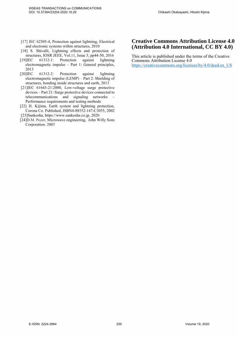
Fig. 12 shows the measured Smith chart using the
network analyzer. The Smith diagram is normalized impedance that has a 1: 1 relationship with the reflectance on the complex plane of the reflectance. The upper part of Fig. 12, it works as an inductor +jX. On the other hand, the lower part of Fig.12, it works as a capacitor -jX.
Fig.12 Smith chart
It showed that the impedance was almost 50 Ω for a
signal frequency of 2GHz. However it showed that the impedance was high 34kΩ for low frequency of 1MHz.
It means that new SPD works as high impedance for lightning surges having low frequency of 1MHz or less.
The feature of this coaxial SPD is that it electrically insulates the antenna side and the BTS side. As a result, lightning surges do not enter the BTS side, so it is possible to prevent the electronic components from being destroyed. In addition, it is designed according to the frequency and can be applied to various wireless devices.
Frequency : 2.11 -2.17GHz Upper -left Antenna side
Insertion loss V=0.1dB/div
Upper - right BTS side Insertion loss V=0.1dB/div
Lower-left Antenna side VSWR V=005/div
Lower-right BTS side VSWR V=0.05/div
Conventinal SPD with GDT
New SPD with double stub
R
+jX(Inductor)
-jX(Capacitor)
0Ω 50Ω
∞
2GHz 47.766Ω 639pH
1MHz -34.165kΩ 4.65pF
WSEAS TRANSACTIONS on COMMUNICATIONS DOI: 10.37394/23204.2020.19.29 Chikashi Okabayashi, Hitoshi Kijima
E-ISSN: 2224-2864 253 Volume 19, 2020
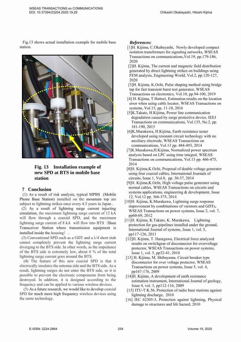
Fig.13 shows actual installation example for mobile base station.
Fig. 13 Installation example of
new SPD at BTS in mobile base
station
7 Conclusion (1) As a result of risk analysis, typical MPBS (Mobile
Phone Base Station) installed on the mountain top are subject to lightning strikes once every 4.5 years in Japan .
(2) As a result of lightning surge current injecting simulation, the maximum lightning surge current of 12 kA will flow through a coaxial SPD, and the maximum lightning surge current of 8 kA will flow into BTS(Base Transceiver Station where transmission equipment is installed inside the housing).
(3) Conventional SPD such as a GDT and a λ/4 short stub cannot completely prevent the lightning surge current diverging to the BTS side. In other words, as the impedance of the BTS side is extremely low, about 4 % of the total lightning surge current goes around the BTS.
(4) The feature of this new coaxial SPD is that it electrically insulates the antenna side and the BTS side. As a result, lightning surges do not enter the BTS side, so it is possible to prevent the electronic components from being destroyed. In addition, it is designed according to the frequency and can be applied to various wireless devices.
(5) As a future research, we would like to develop coaxial SPD for much more high frequency wireless devices using the same technology.
References: [1]H. Kijima, C.Okabayashi, Newly developed compact
isolation transformers for signaling networks, WSEAS Transactions on communications,Vol.19, pp.179-186, 2020
[2]H. Kijima, The current and magnetic field distribution generated by direct lightning strikes on buildings using FEM analysis, Engineering World, Vol.2, pp.120-127, 2020
[3]H. Kijima, K.Ochi, Pulse shaping method using bridge tap for fast transient burst test generator, WSEAS Transactions on electronics, Vol.10, pp.94-100, 2019
[4] H. Kijima, T.Hattori, Estimation results on the location error when using cable locator, WSEAS Transactions on systems, Vol.15, pp. 11-18, 2016
[5]K.Takato, H.Kijima, Power line communication degradation caused by surge protective device, IEEJ Transactions on communications, Vol.135, No.2, pp. 181-190, 2015
[6]K.Murakawa, H.Kijima, Earth resistance tester developed using resonant circuit technology with no auxiliary electrode, WSEAS Transactions on communications, Vol.13 pp. 484-493, 2014
[7]K.Murakawa,H.Kijima, Normalized power spectrum analysis based on LPC using time integral, WSEAS Transactions on communications, Vol.13 pp. 466-475, 2014
[8]H. Kijima,K.Ochi, Proposal of double voltage generator using four coaxial cables, International Journals of circuits, Issue 1, Vol.8, pp. 30-37, 2014
[9]H. Kijima,K.Ochi, High voltage pulse generator using normal cables, WSEAS Transactions on circuits and systems applications, engineering & development, Issue 12, Vol.12 pp. 366-375, 2014
[10]H. Kijima, K.Murakawa, Lightning surge response improvement by combinations of varistors and GDTs, WSEAS Transactions on power systems, Issue 2, vol. 7, pp60-69, 2012
[11]H. Kijima, K.Takato, K. Murakawa, Lightning protection for gas-pipelines installed under the ground, International Journal of systems, Issue 1, vol. 5, pp117-126, 2011
[12]H. Kijima, T. Hasegawa, Electrical force analyzed results on switchgear of disconnector for overvoltage protector, WSEAS Transactions on power systems, Issue 1, vol. 5, pp32-41, 2010
[13] H. Kijima, M. Shibayama, Circuit breaker type disconnector for over voltage protector, WSEAS Transactions on power systems, Issue 5, vol. 4, pp167-176, 2009
[14]H. Kijima, A development of earth resistance estimation instrument, International Journal of geology, Issue 4, vol. 3, pp112-116, 2009
[15] ITU-T K.56, Protection of radio base stations against lightning discharge, 2010
[16] IEC 62305-3, Protection against lightning, Physical damage to structures and life hazard, 2010
WSEAS TRANSACTIONS on COMMUNICATIONS DOI: 10.37394/23204.2020.19.29 Chikashi Okabayashi, Hitoshi Kijima
E-ISSN: 2224-2864 254 Volume 19, 2020
[17] IEC 62305-4, Protection against lightning, Electrical and electronic systems within structures, 2010
[18] S. Shivalli, Lightning effects and protection of structures, IOSR JEEE, Vol.11, Issue 3, pp44-50, 2016
[19]IEC 61312-1: Protection against lightning electromagnetic impulse – Part 1: General principles, 2013
[20]IEC 61312-2: Protection against lightning electromagnetic impulse (LEMP) – Part 2: Shielding of structures, bonding inside structures and earth, 2013
[21]IEC 61643-21:2000, Low-voltage surge protective devices – Part 21: Surge protective devices connected to telecommunications and signaling networks – Performance requirements and testing methods
[22] H. Kijima, Earth system and lightning protection, Corona Co. Published, ISBN4-88552-147-C3055, 2002
[23]Sankosha, https://www.sankosha.co.jp, 2020 [24]D.M. Pozer, Microwave engineering, John Willy Sons
Corporation. 2003
Creative Commons Attribution License 4.0 (Attribution 4.0 International, CC BY 4.0)
This article is published under the terms of the Creative Commons Attribution License 4.0 https://creativecommons.org/licenses/by/4.0/deed.en_US
WSEAS TRANSACTIONS on COMMUNICATIONS DOI: 10.37394/23204.2020.19.29 Chikashi Okabayashi, Hitoshi Kijima
E-ISSN: 2224-2864 255 Volume 19, 2020