Lecture Set 3 - Purdue Engineeringsudhoff/ece321/Lecture Set 3.pdf · Lecture Set 3 Variable...
48
Lecture Set 3 Variable Reluctance Stepper Motors S.D. Sudhoff Spring 2018
Transcript of Lecture Set 3 - Purdue Engineeringsudhoff/ece321/Lecture Set 3.pdf · Lecture Set 3 Variable...
Lecture Set 3
Variable Reluctance Stepper Motors
S.D. Sudhoff
Spring 2018
2
Reading
• Electromechanical Motion Devices, 2nd
Edition�Sections 9.1-9.5
3
VR Stepper Motor
• Characteristics
• Uses
4
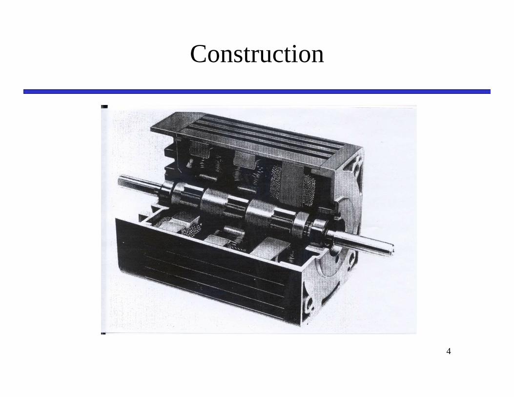
Construction
5
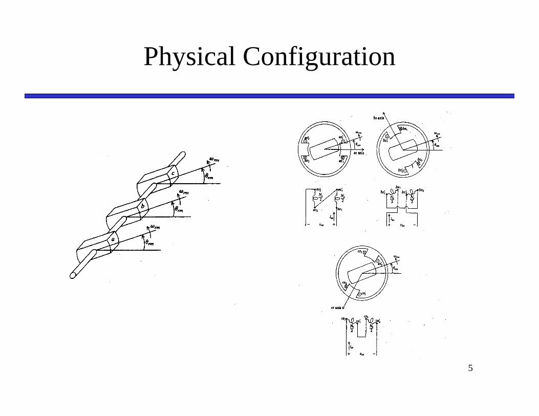
Physical Configuration
Physical Configuration
6
7
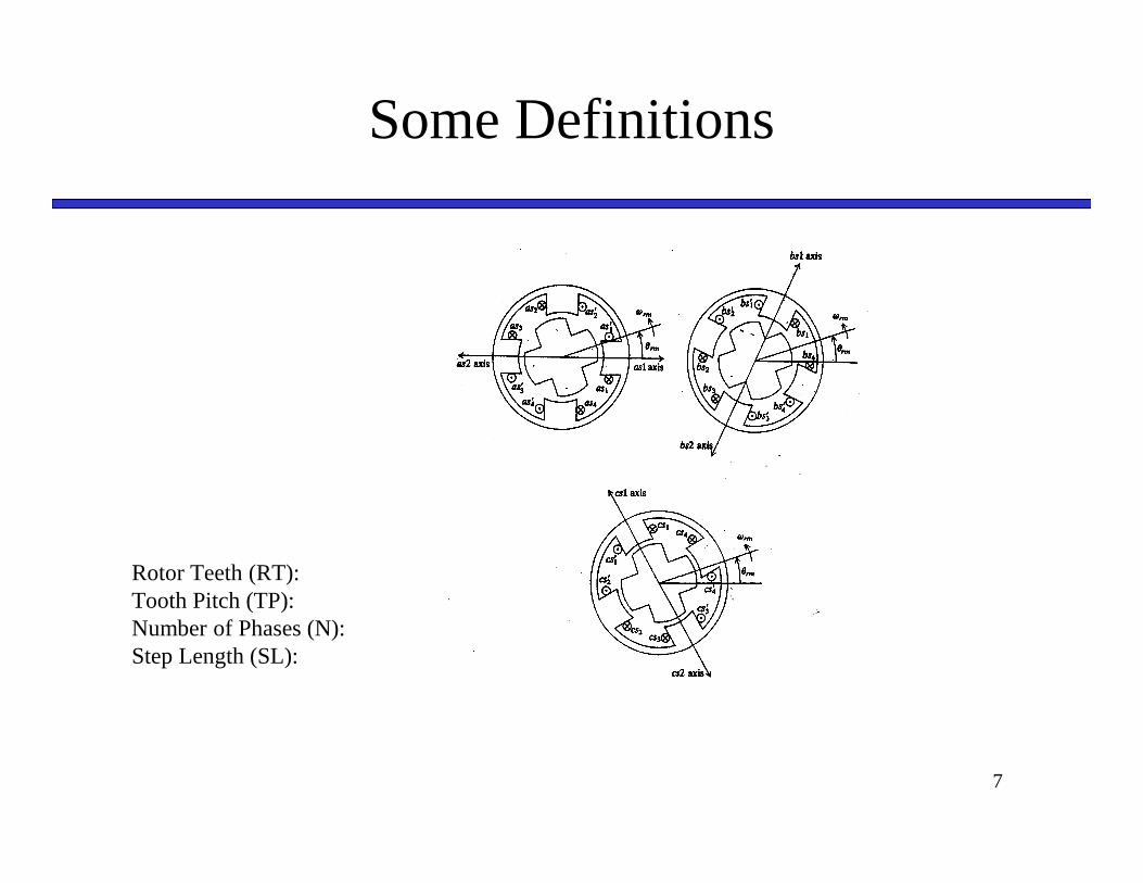
Some Definitions
Rotor Teeth (RT):Tooth Pitch (TP):Number of Phases (N):Step Length (SL):
8
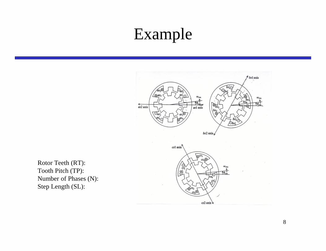
Example
Rotor Teeth (RT):Tooth Pitch (TP):Number of Phases (N):Step Length (SL):
9
Analysis of VR Stepper
• Voltage Equations
• Flux Linkage Equations
• Torque Equation
• Mechanical Dynamics
10
VR Stepper Voltage Equations
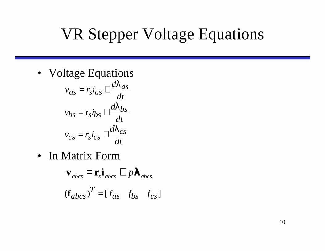
• Voltage Equations
• In Matrix Form
dt
dirv asassas
λ+=
dt
dirv bsbssbs
λ+=
dt
dirv cscsscs
λ+=
abcs s abcs abcsp= +v r i λ
] [)( csbsasT
abcs fff=f
11
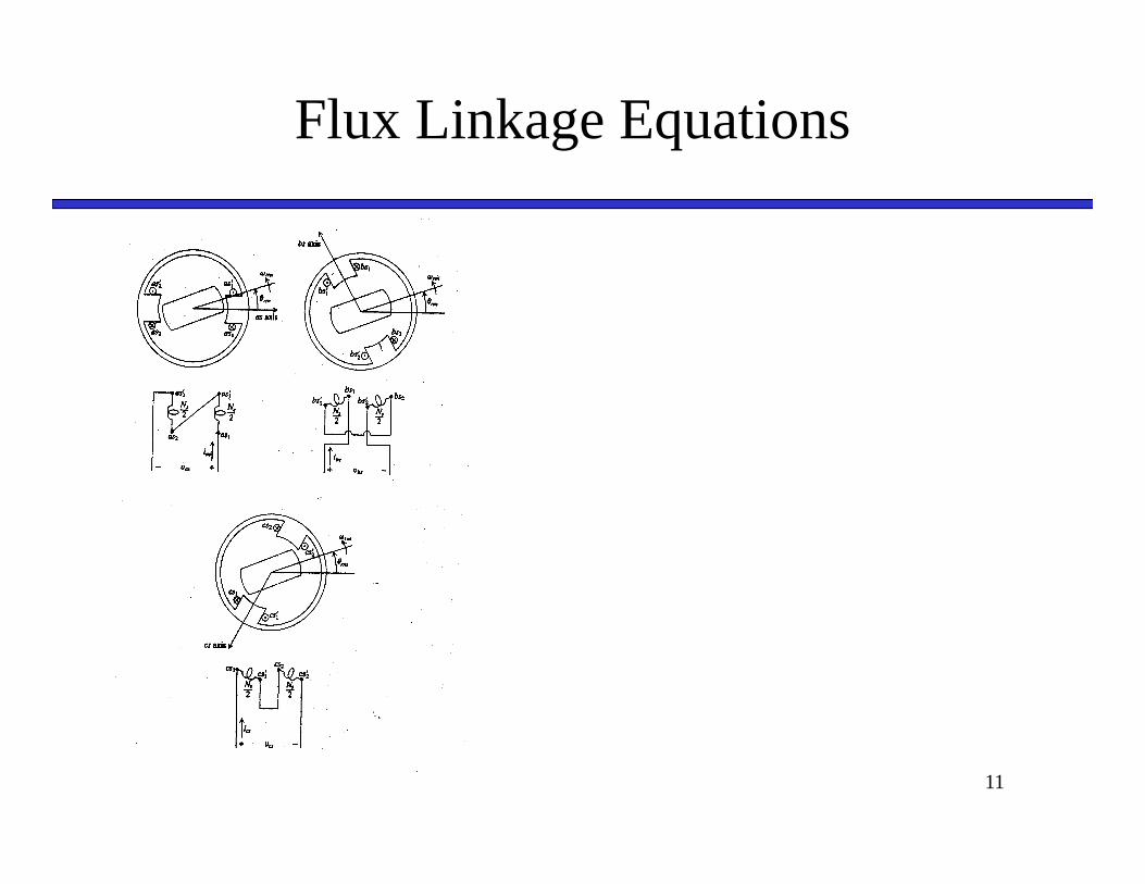
Flux Linkage Equations

Flux Linkage Equations
12
Flux Linkage Equations
13
Flux Linkage Equations
14
15
Flux Linkage Equations
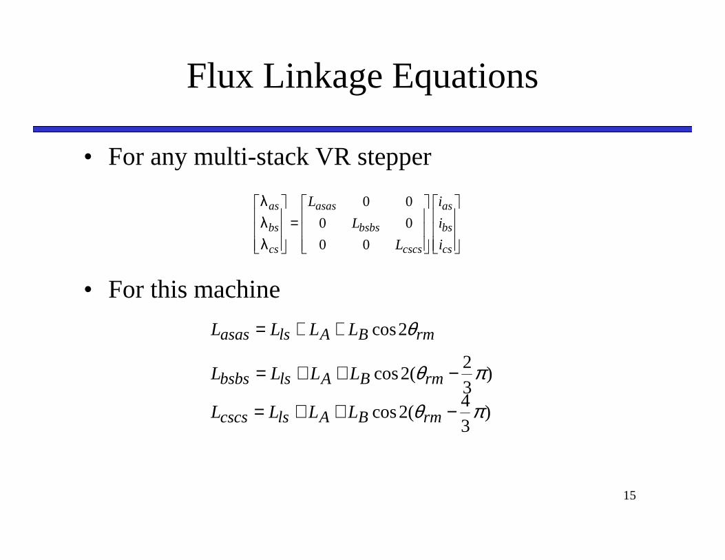
• For any multi-stack VR stepper
• For this machine
=
cs
bs
as
cscs
bsbs
asas
cs
bs
as
i
i
i
L
L
L
00
00
00
λ
λ
λ
rmBAlsasas LLLL θ2cos++=
)32
(2cos πθ −++= rmBAlsbsbs LLLL
)34
(2cos πθ −++= rmBAlscscs LLLL
16
Flux Linkage Equations
17
Flux Linkage Equations
18
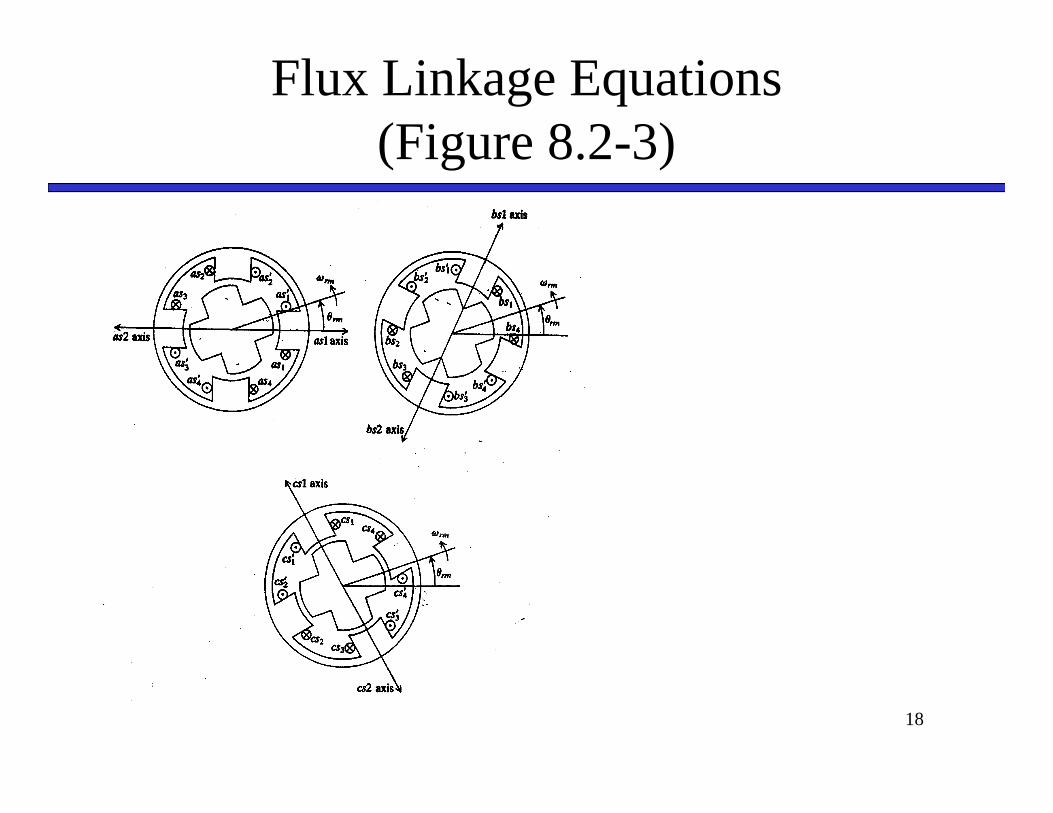
Flux Linkage Equations(Figure 8.2-3)
19
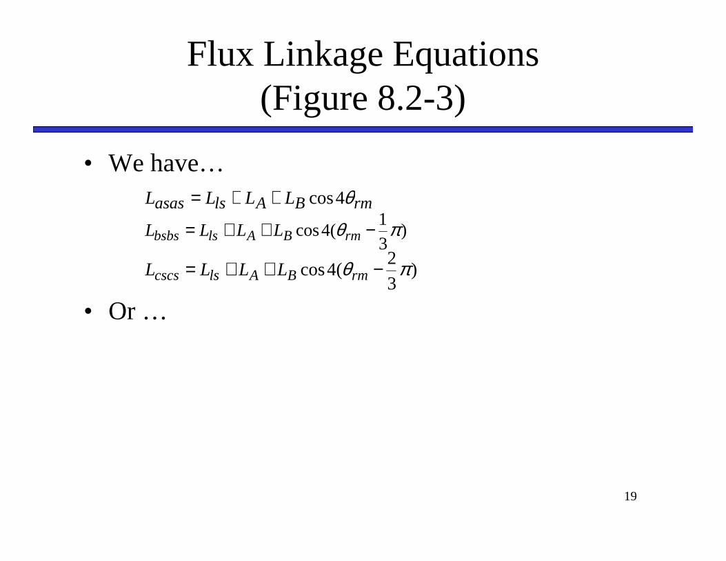
Flux Linkage Equations(Figure 8.2-3)
• We have…
• Or …
rmBAlsasas LLLL θ4cos++=
)31
(4cos πθ −++= rmBAlsbsbs LLLL
)32
(4cos πθ −++= rmBAlscscs LLLL
20
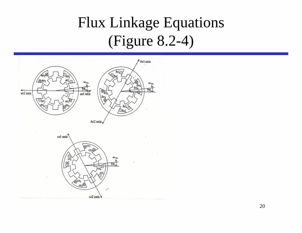
Flux Linkage Equations(Figure 8.2-4)
21
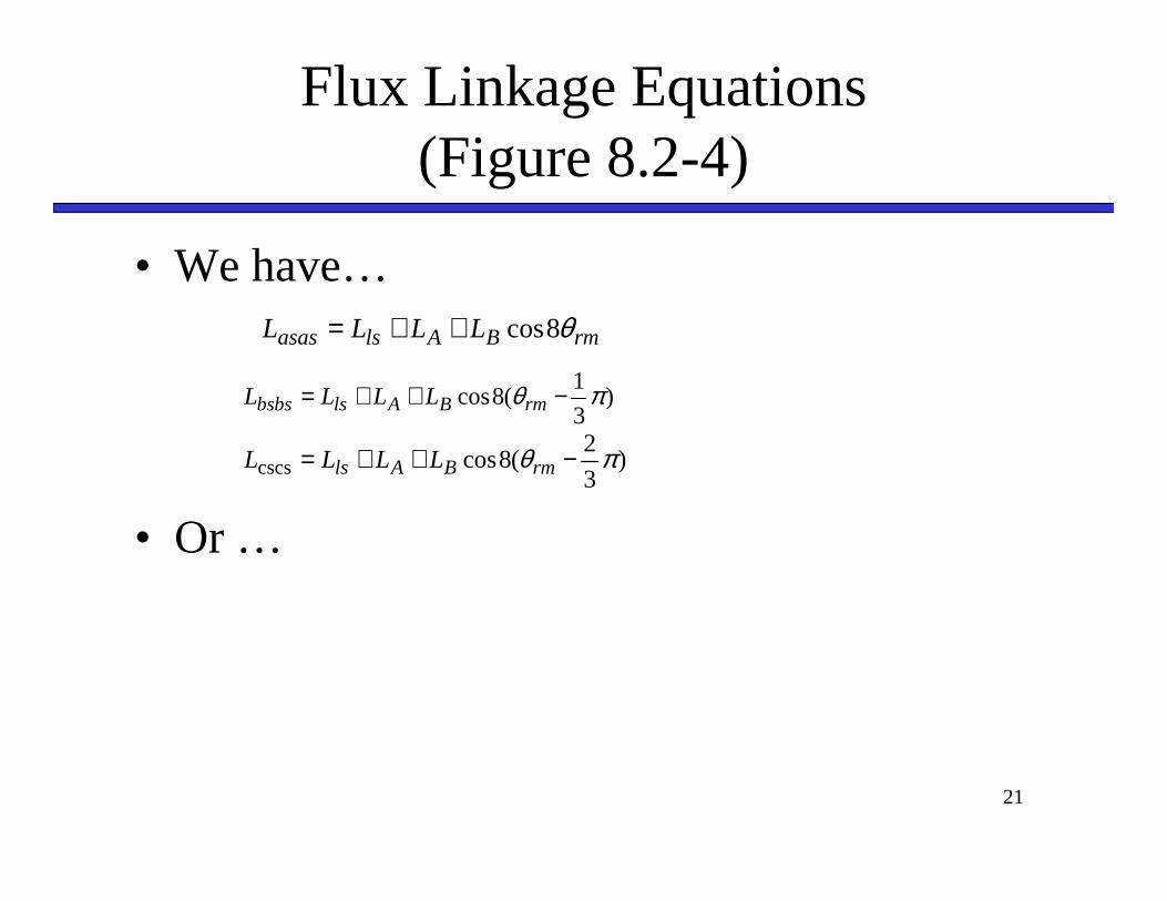
Flux Linkage Equations(Figure 8.2-4)
• We have…
• Or …
rmBAlsasas LLLL θ8cos++=
)3
1(8cos πθ −++= rmBAlsbsbs LLLL
)3
2(8coscscs πθ −++= rmBAls LLLL
22
Generalized Flux Linkage Eqns
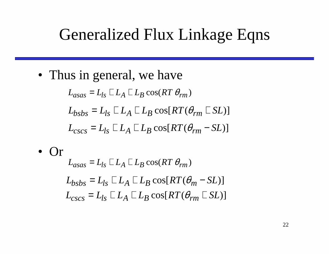
• Thus in general, we have
• Or
)cos( rmBAlsasas RTLLLL θ++=
)](cos[ SLRTLLLL rmBAlsbsbs +++= θ
)](cos[ SLRTLLLL rmBAlscscs −++= θ
)cos( rmBAlsasas RTLLLL θ++=
)](cos[ SLRTLLLL mBAlsbsbs −++= θ)](cos[ SLRTLLLL rmBAlscscs +++= θ

23
Derivation of Torque

24
Derivation of Torque
25
Derivation of Torque
26
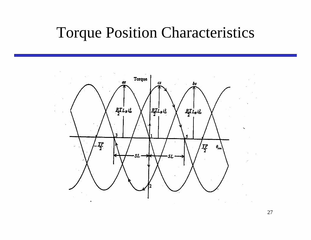
Electromagnetic Torque
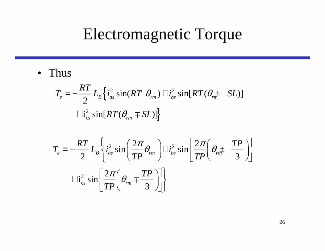
• Thus
{}
2 2
2cs
sin( ) sin[ ( )]2
i sin[ ( )]
e B as rm bs rm
rm
RTT L i RT i RT SL
RT SL
θ θ
θ
= − + ±
+ ∓
2 2
2cs
2 2sin sin
2 3
2 i sin
3
e B as rm bs rm
rm
RT TPT L i i
TP TP
TP
TP
π πθ θ
π θ
= − + ±
+ ∓
27
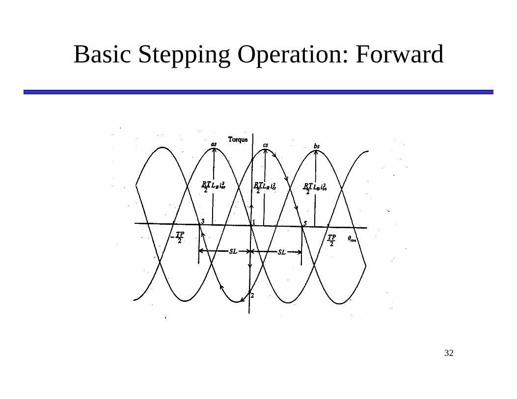
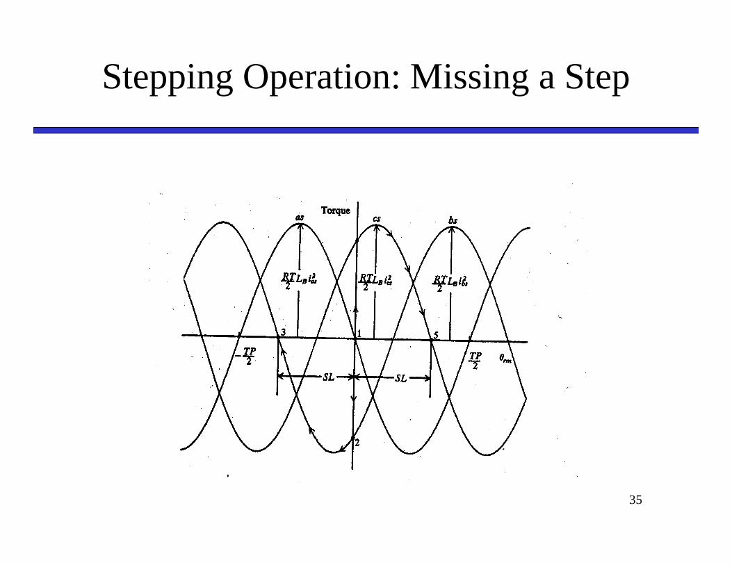
Torque Position Characteristics
28
Mechanical Dynamics
29
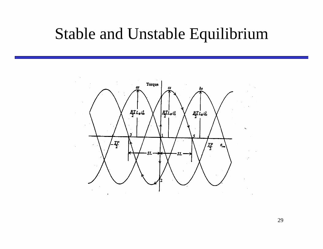
Stable and Unstable Equilibrium
30
Example
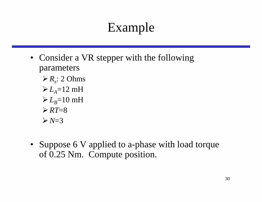
• Consider a VR stepper with the following parameters�Rs: 2 Ohms�LA=12 mH�LB=10 mH�RT=8�N=3
• Suppose 6 V applied to a-phase with load torque of 0.25 Nm. Compute position.
31
Solution
32
Basic Stepping Operation: Forward
33
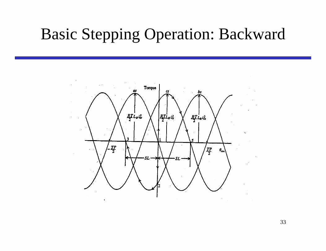
Basic Stepping Operation: Backward
34
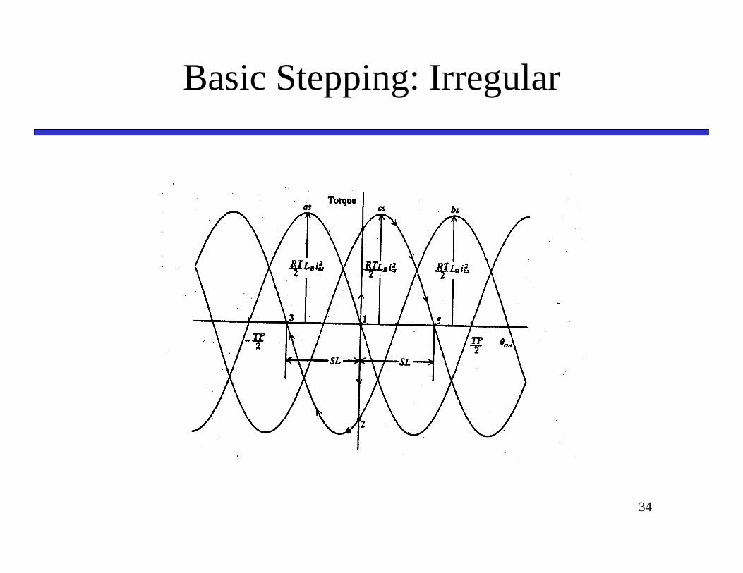
Basic Stepping: Irregular
35
Stepping Operation: Missing a Step
36
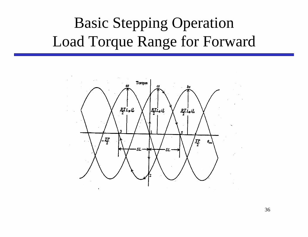
Basic Stepping OperationLoad Torque Range for Forward
37
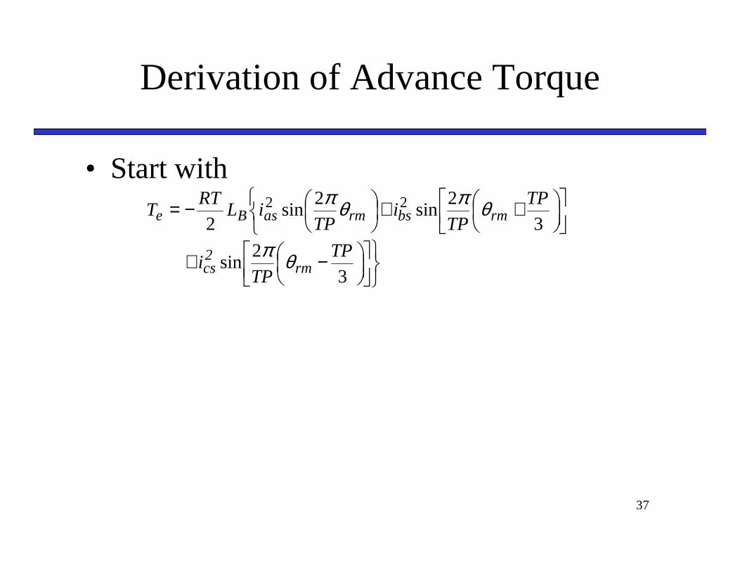
Derivation of Advance Torque
• Start with
−+
++
−=
32
sin
32
sin2
sin2
22
TP
TPi
TP
TPi
TPiL
RTT
rm2cs
rmbsrmasBe
θπ
θπθπ
38
Derivation of Advance Torque
39
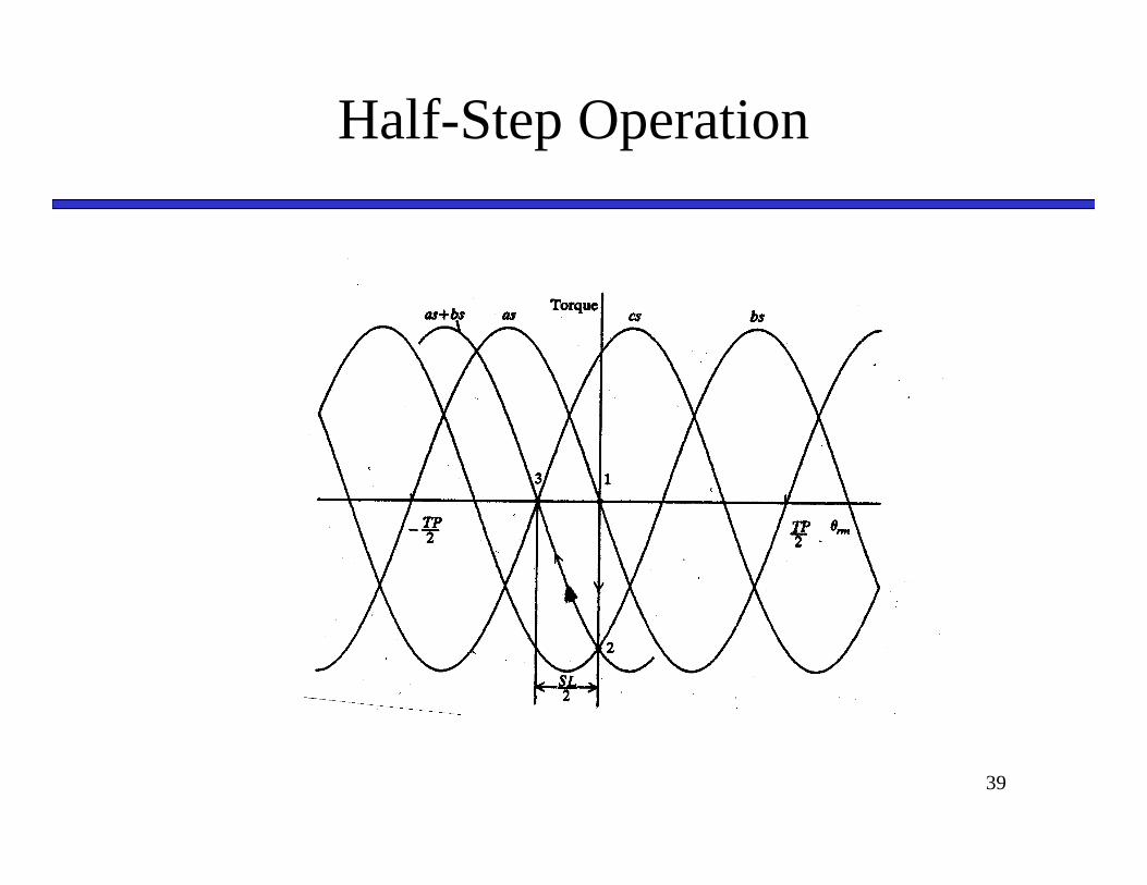
Half-Step Operation
40
Driving VR Stepper Motor
• Common solution
41
Driving VR Stepper
• Typical waveforms
42
Driving VR Stepper
• Better (but more expensive) solution

43
Driving VR Stepper
• Typical waveforms
44
Example
• Consider a multistack VR stepper motor with N=3 and 8 rotor teeth being fed from a single transistor per stack circuit. If the dc voltage is 12 V, the transistor drop is 1 V, and the diode drop is 2 V, sketch the a-phase voltage waveform if the machine is traveling at 20 rad/s (average speed).
45
Solution
46
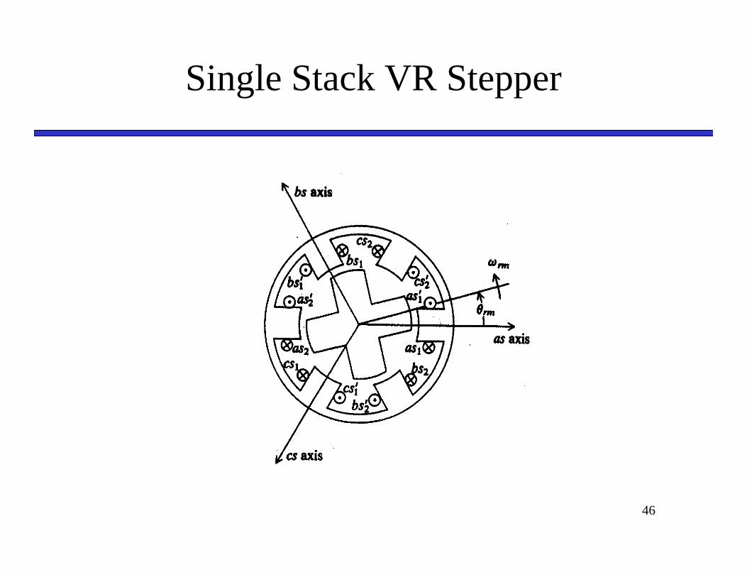
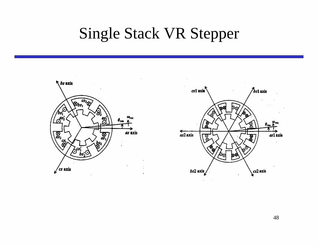
Single Stack VR Stepper
47
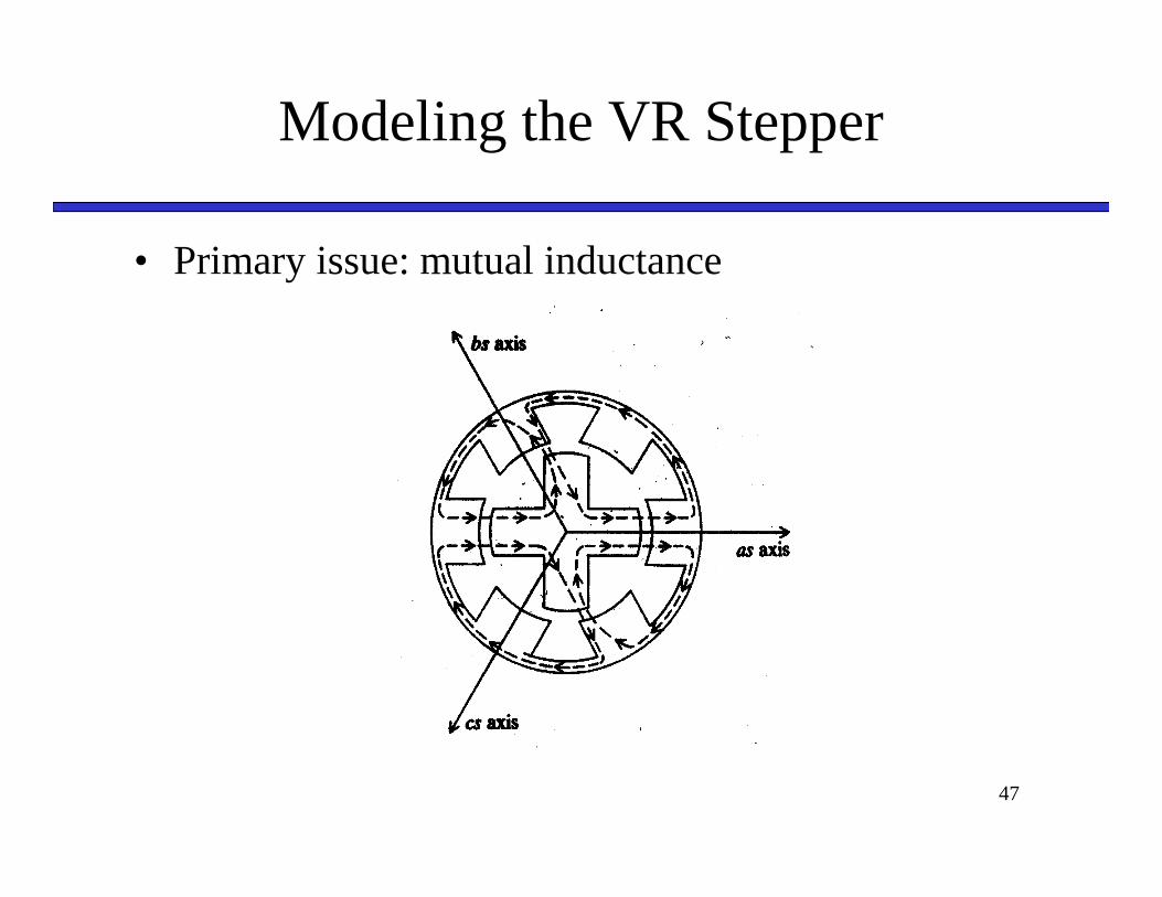
Modeling the VR Stepper
• Primary issue: mutual inductance
48
Single Stack VR Stepper