
Lecture Note – 6 Moment-Curvature (M-φ) Relation - I · 31 Lecture Note – 7 Moment-Curvature...
26
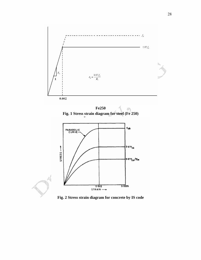
27 Lecture Note – 6 Moment-Curvature (M-φ) Relation - I M-φcharacteristics considering IS: 456: The actual moment-curvature relationship of R.C. prismatic section is obtained from stress-strain diagram of concrete and steel. Starting from the basic equations, expressions for the axial force and moment carrying capacity of the section are calculated in non- dimensional form. The equation of the stress strain diagram of the parabolic part for concrete is 2 0 0 2 cu σ ε ε σ ε ε ⎛ ⎞ = − ⎜ ⎟ ⎝ ⎠ …………………………………(1) subject to the following limiting conditions: ( Figs. 1 and 2) 1. at ε = 0 , σ = 0, 2. at ε = ε 0 , σ = σ cu , 3. at ε = ε 0 , ε σ d d = 0. The permissible compressive stress in concrete are considered as: σ cu = 0.446f ck Under any loading condition, the section undergoes strains and consequent stresses. A linear strain distribution over the depth of cross-section is assumed for stress distribution in concrete and steel(Figs.1 and 2), giving rise to two possible cases: 1. 0 ≤ ε 4 ≤ ε 0 and 2. ε 0 ≤ ε 4 ≤ ε u ⎥ ⎥ ⎦ ⎤ ⎢ ⎢ ⎣ ⎡ ⎟ ⎠ ⎞ ⎜ ⎝ ⎛ − = ∴ 2 002 . 0 002 . 0 2 446 . 0 ε ε σ ck f For 002 . 0 < ε =0.446 for ck f 0035 . 0 002 . 0 ≤ ≤ ε
Transcript of Lecture Note – 6 Moment-Curvature (M-φ) Relation - I · 31 Lecture Note – 7 Moment-Curvature...
27
Lecture Note – 6
Moment-Curvature (M-φ) Relation - I M-φcharacteristics considering IS: 456: The actual moment-curvature relationship of R.C. prismatic section is obtained from stress-strain diagram of concrete and steel. Starting from the basic equations, expressions for the axial force and moment carrying capacity of the section are calculated in non-dimensional form. The equation of the stress strain diagram of the parabolic part for concrete is
2
0 0
2cu
σ ε εσ ε ε
⎛ ⎞= − ⎜ ⎟
⎝ ⎠…………………………………(1)
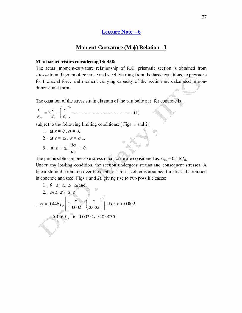
subject to the following limiting conditions: ( Figs. 1 and 2) 1. at ε = 0 , σ = 0, 2. at ε = ε0 , σ = σcu,
3. at ε = ε0, εσ
dd = 0.
The permissible compressive stress in concrete are considered as: σcu = 0.446fck
Under any loading condition, the section undergoes strains and consequent stresses. A linear strain distribution over the depth of cross-section is assumed for stress distribution in concrete and steel(Figs.1 and 2), giving rise to two possible cases:
1. 0 ≤ ε4 ≤ ε0 and 2. ε0 ≤ ε 4 ≤ εu
⎥⎥⎦
⎤
⎢⎢⎣
⎡⎟⎠⎞
⎜⎝⎛−=∴
2
002.0002.02446.0 εεσ ckf For 002.0<ε
=0.446 for ckf 0035.0002.0 ≤≤ ε
28
Fe250
Fig. 1 Stress strain diagram for steel (Fe 250)
Fig. 2 Stress strain diagram for concrete by IS code
29
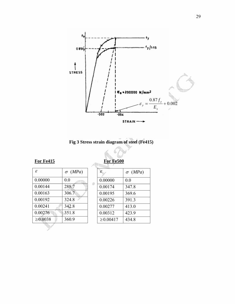
Fig 3 Stress strain diagram of steel (Fe415)
For Fe415 For Fe500
ε )(MPaσ
0.00000 0.0 0.00144 288.7 0.00163 306.7 0.00192 324.8 0.00241 342.8 0.00276 351.8 ≥0.0038 360.9
ε )(MPaσ
0.00000 0.0 0.00174 347.8 0.00195 369.6 0.00226 391.3 0.00277 413.0 0.00312 423.9 ≥0.00417 434.8
002.087.0
+=s
yy E
fε
30
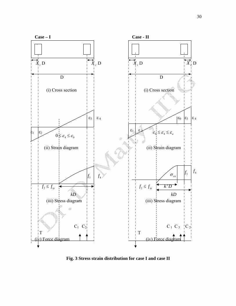
Case – I Case - II cX
tX D cX D tX D D cX D D (i) Cross section (i) Cross section (ii) Strain diagram (ii) Strain diagram 2 syf f≤
kD (iii) Stress diagram C1 C2
T (iv) Force diagram
f3
ε1 ε2
ε3 ε 4
ε1 ε 2
ε0 ε3 ε 4
4 00 ε ε≤ ≤ 0 4 uε ε ε≤ ≤
3f 4f cuσ 4f
Fig. 3 Stress st
2 syf f≤ k ' D
kD (iii) Stress diagram
C 1 C 3
T
(iv) Force diagram
rain distribution for case I and case II
C 2
31
Lecture Note – 7
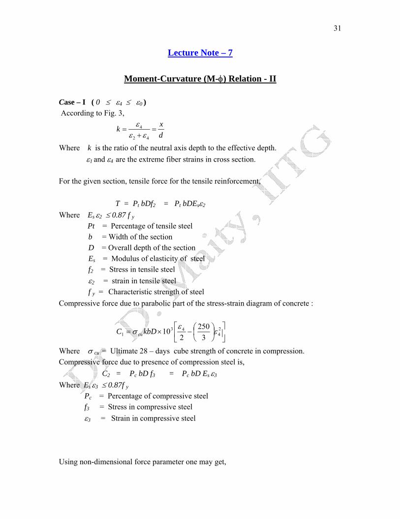
Moment-Curvature (M-φ) Relation - II Case – I ( 0 ≤ ε4 ≤ ε0 ) According to Fig. 3,
4
2 4
xkd
εε ε
= =+
Where k is the ratio of the neutral axis depth to the effective depth. ε1 and ε4 are the extreme fiber strains in cross section. For the given section, tensile force for the tensile reinforcement, T = Pt bDf2 = Pt bDEsε2
Where Es ε2 ≤ 0.87 f y
Pt = Percentage of tensile steel b = Width of the section D = Overall depth of the section Es = Modulus of elasticity of steel f2 = Stress in tensile steel ε2 = strain in tensile steel f y = Characteristic strength of steel Compressive force due to parabolic part of the stress-strain diagram of concrete :
⎥⎦
⎤⎢⎣
⎡⎟⎠⎞
⎜⎝⎛−×= 2
443
1 3250
210 ε
εσ kbDC cu
Where σ cu = Ultimate 28 – days cube strength of concrete in compression. Compressive force due to presence of compression steel is, C2 = Pc bD f3 = Pc bD Es ε3
Where Es ε3 ≤ 0.87f y
Pc = Percentage of compressive steel f3 = Stress in compressive steel ε3 = Strain in compressive steel Using non-dimensional force parameter one may get,
32
υ = bD
TCCNN
cuσ−+
= 21
0
=cu
t
cu
c fPfPk
σσε
ε 2324
4 '121
2'
−+⎥⎦
⎤⎢⎣
⎡⎟⎠⎞
⎜⎝⎛− ………….(2)
Where f3 = Es ε3 ≤ 0.87 f y
f2 = Es ε2 ≤ 0.87 f y
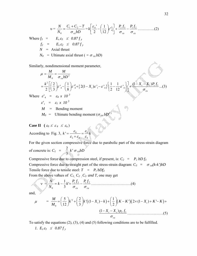
N = Axial thrust N0 = Ultimate axial thrust ( = σ cu bD) Similarly, nondimensional moment parameter,
µ 20 bD
MMM
cuσ==
{ }2
2 34 4 1 4 4
(1 )2 1 1 1' ' 2(1 ) ' ' '2 3 8 2 12
t c ct
cu
X X P fk Xε ε ε ε εσ
− −⎡ ⎤⎛ ⎞ ⎛ ⎞ ⎧ ⎫+ − − − +⎨ ⎬⎜ ⎟ ⎜ ⎟⎢ ⎥⎝ ⎠ ⎝ ⎠ ⎩ ⎭⎣ ⎦ = − ...(3)
Where 4'ε = ε4 x 10 3
1'ε = ε1 x 10 3
M = Bending moment M0 = Ultimate bending moment (σ cu bD2 )
Case II ( ε0 ≤ ε 4 ≤ εu )
According to Fig. 3, 0 0
2 4 4
'k kε εε ε ε
= =+
For the given section compressive force due to parabolic part of the stress-strain diagram
of concrete is: C1 = 32 k’ σ cubD
Compressive force due to compression steel, if present, is: C2 = Pc bD f3
Compressive force due to straight part of the stress-strain diagram: C3 = σ cu(k-k’)bD Tensile force due to tensile steel: T = Pt bDf2
From the above values of C1, C2 , C3 and T, one may get
cu
t
cu
c fPfPkk
NN
σσ23
0
'31
−+−=ν = …………….……………(4)
and,
µ = ( ) ( )('2
0
5 2 1' (1 ) ' 2 (1 ) '12 3 2t
M k k X k K K X K KM
⎛ ⎞ ⎛ ⎞ ⎛ ⎞= + − − + − × − + −⎜ ⎟ ⎜ ⎟ ⎜ ⎟⎝ ⎠ ⎝ ⎠ ⎝ ⎠
)t +
3(1 )t c C
cu
X X p fσ
− − ………………….……(5)
To satisfy the equations (2), (3), (4) and (5) following conditions are to be fulfilled. 1. Es ε3 ≤ 0.87 f y
33
2. Es ε2 ≤ 0.87 f y
Putting different values of ν in the equations (2) and (4) and assigning some specific values of ε4 (ε4 ≤ 0.0035), corresponding values are calculated. The strain of concrete being known or assumed, the rotation capacity of the structure is calculated. Corresponding to this rotation capacity, moment carrying capacity of the structure is calculated from the equations (3) and (5). For specific values of compression and tensile steel, the value of ∆ε (ε1+ε4) and µ ( = M / M0 ) are calculated.
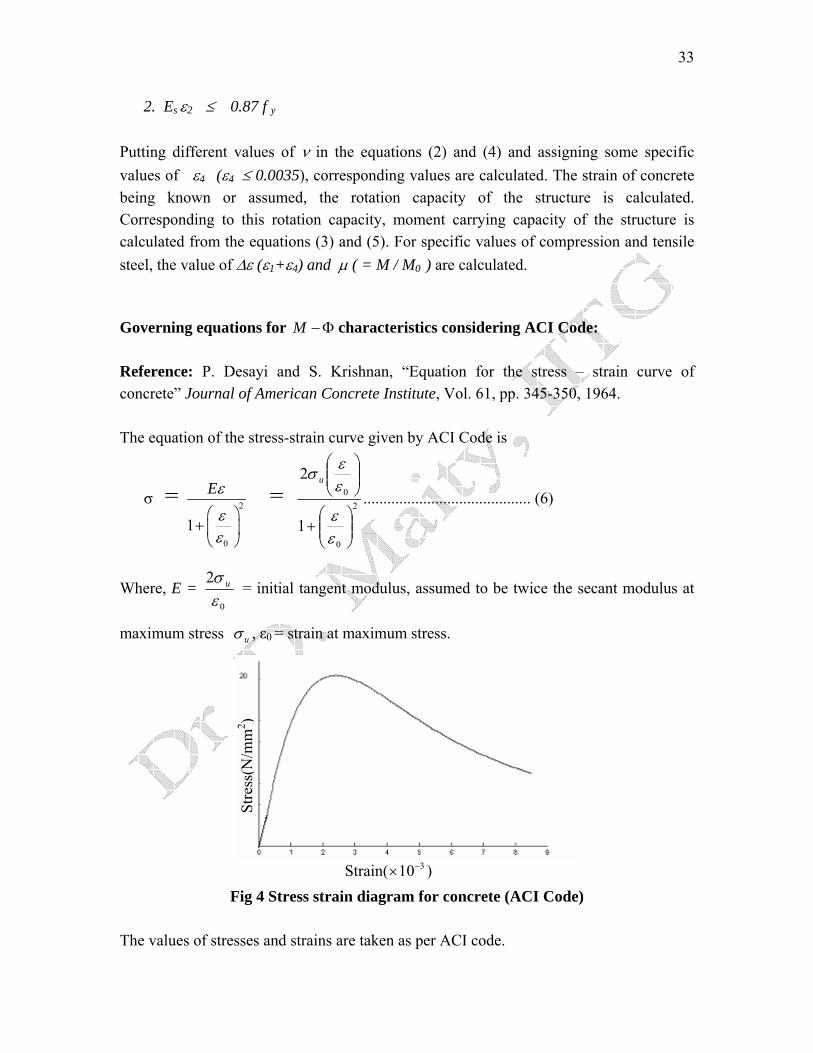
Governing equations for M −Φ characteristics considering ACI Code: Reference: P. Desayi and S. Krishnan, “Equation for the stress – strain curve of concrete” Journal of American Concrete Institute, Vol. 61, pp. 345-350, 1964. The equation of the stress-strain curve given by ACI Code is
2
0
0
1
2
⎟⎟⎠
⎞⎜⎜⎝
⎛+
⎟⎟⎠
⎞⎜⎜⎝
⎛
εε
εεσ u
= 2
0
1
Eε
εε
⎛ ⎞+ ⎜ ⎟⎝ ⎠
= .......................................... (6)
0
2εσ u
u
Where, E = = initial tangent modulus, assumed to be twice the secant modulus at
maximum stress σ , ε0 = strain at maximum stress.
Stre
ss(N
/mm
2 )
Strain( 310−× )
Fig 4 Stress strain diagram for concrete (ACI Code)
The values of stresses and strains are taken as per ACI code.
34
Strain distribution over the depth of section is considered as linear. According to Fig. 4,
4
2 4
k εε ε
=+
Where k = Ratio of the natural axis depth to the effective depth. (ε2 and ε4 are the extreme fiber strains in cross section.) For the given section, tensile force for the tensile reinforcement, T = Pt bdf2 = Pt bdEsε2
Where Es ε2 ≤ 0.87 f y
Pt = Percentage of tensile steel b = Width of the section D = Overall depth of the section Es = Modulus of elasticity of steel f2 = Stress in tensile steel ε2 = Strain in tensile steel f y = Characteristic strength of steel Compressive force due to parabolic part of the stress-strain diagram of concrete :
C1 = ⎥⎥⎦
⎤
⎢⎣
⎡⎟⎟⎠
⎞⎜⎜⎝
⎛+
2
0
1εε
0
kbduσε
ln ⎢
Where σu = Ultimate 28 – days cube strength of concrete in compression. Compressive force due to the presence of compression steel, is C2 = Pc bd f3 = Pcbd Esε3
Where Es ε3 ≤ 0.87f y
Pc = Percentage of compressive steel f3 = Stress in compressive steel ε3 = Strain in compressive steel Using non-dimensional force parameter,
NNo
ν =1 2
u
C C Tbdσ
+ − = ku
t
u
c fPfPσσε
εεε 23
2
0
4
4
0 1ln −+⎥⎥⎦
⎤
⎢⎢⎣
⎡⎟⎟⎠
⎞⎜⎜⎝
⎛+ ………….(7) =
Where f3 = Es ε3 ≤ 0.87 f y
f2 = Es ε2 ≤ 0.87 f y
N = Axial thrust N0 = Ultimate axial thrust ( = σ cu bD) Similarly, nondimensional moment parameter,
35
µ = 20 bD
MMM
cuσ=
= ( ) ( )2 2 22 104 4
4 024 0 4 0
1 12ln 1 tant c t c
u
sX k Xk εε εε εε ε ε ε σ
−⎡ ⎤ ⎡ ⎤− −⎛ ⎞ ⎛ ⎞⎢ ⎥+ − − +⎢ ⎥⎜ ⎟ ⎜ ⎟⎢ ⎥⎝ ⎠ ⎝ ⎠⎣ ⎦⎣ ⎦
X P E−
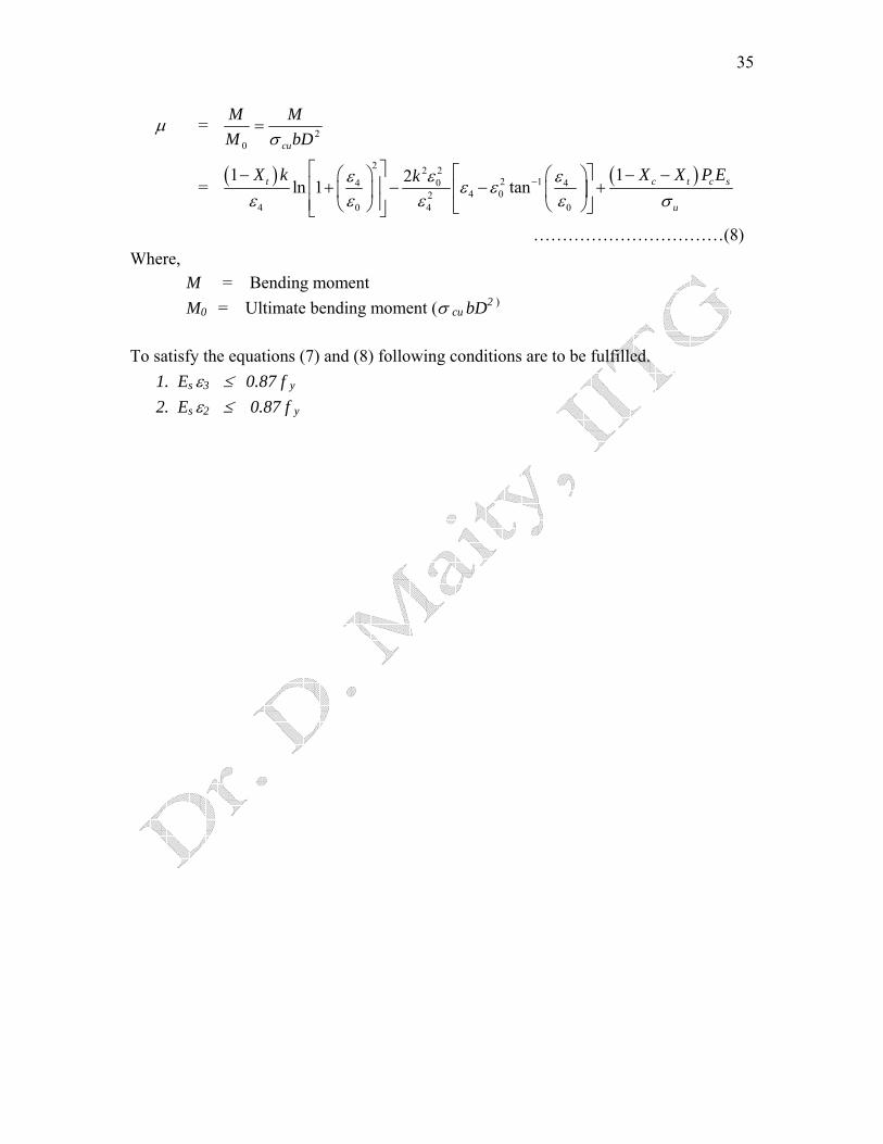
……………………………(8) Where, M = Bending moment M0 = Ultimate bending moment (σ cu bD2 )
To satisfy the equations (7) and (8) following conditions are to be fulfilled.
1. Es ε3 ≤ 0.87 f y
2. Es ε2 ≤ 0.87 f y
36
Lecture Note – 8
Behavior of RC Member: Flexure
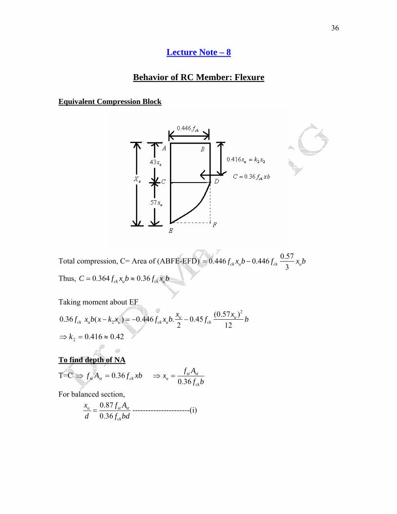
Equivalent Compression Block
Total compression, C= Area of (ABFE-EFD) 0.570.446 0.446
3ck u ck uf x b f x b= −
0.364 0.36ck u ck ux b f x b= ≈
Thus, C f
Taking moment about EF
2
2(0.57 )0.36 ( ) 0.446 . 0.45
2 12u u
ck u u ck u ckx xf x b x k x f x b f b− = − −
42.0416.02 ≈=⇒ k
To find depth of NA
T=C ⇒ xbfAf ckstst 36.0=0.36
st stu
ck
f Axf b
⇒ =
For balanced section, 0.870.36
u st
ck
stx f Ad f=
bd----------------------(i)
37
Limiting value of Xu /d
0.0021.15
ysu
s
fE
ε = + ; Where Mpas5102×=Ε
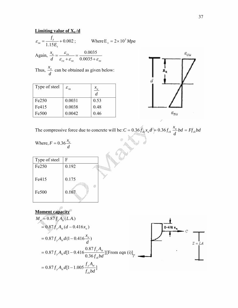
Again, 0.00350.0035
u cu
cu su su
xd
εε ε ε
= =+ +
Thus, dxu can be obtained as given below:
Type of steel suε
dxu
Fe250 Fe415 Fe500
0.0031 0.0038 0.0042
0.53 0.48 0.46
dxf uck36.0= bddx
f uck36.0=The compressive force due to concrete will be:C bdFfck=
Where, 0.36 uxFd
=
Type of steel F Fe250 Fe415 Fe500
0.192 0.175 0.167
Moment capacity
0.87 ( . .)u y stM f A L A=
)416.0(87.0 usty xdAf −
=
)416.01(87.0dx
dAf usty −=
]36.087.0
416.01[87.0bdfAf
dAfck
stysty −= [From eqn (i)]
]005.11[87.0bdfAf
dAfck
stysty −=
38
20.87 [1 ]yy
ck
pff pbd
f= −
2 0.87 1 yuy
ck
pfM f pbd f
⎡ ⎤∴ = −⎢ ⎥
⎣ ⎦
Mu in terms of concrete
( )uuck xdbxfMu
416.036.0 −=
2416.0136.0 bddx
dx
f uuck ⎟
⎠⎞
⎜⎝⎛ −=
Thus, 2u ckM Kf bd= where, 0.36 1 0.416u ux xK
d d⎛ ⎞= −⎜ ⎟⎝ ⎠
Type of steel K Fe250 Fe415 Fe500
0.15 0.14 0.13
Minimum depth for given M u
u
ck
MdKf b
⇒ =2u ckM Kf bd=
For Fe250, K = 0.15, bfM
ck
u66.6=d
bfM
ck
u1.7=d For Fe415, K = 0.14,
Expression for Steel Area for Balanced Singly Reinforced Section From the equilibrium condition: T = C ucksty bxfAf 36.087.0 =⇒
/0.36
0.87st ck u
y y
ckA f x fkbd f d f
∴ = ⋅ =
39
Now, assuming 100×=bdA
p st ; y
ck
ff
kp /
100=∴
Thus, / 0.36 100100 41.30.87
y u u
ck
f x xp kf d d
×= = ⋅ =
Thus the percentage of balanced reinforcement pB will be as shown in the table below: Steel x/d
⎟⎠⎞
⎜⎝⎛
ck
yf
fp pB (for M20)
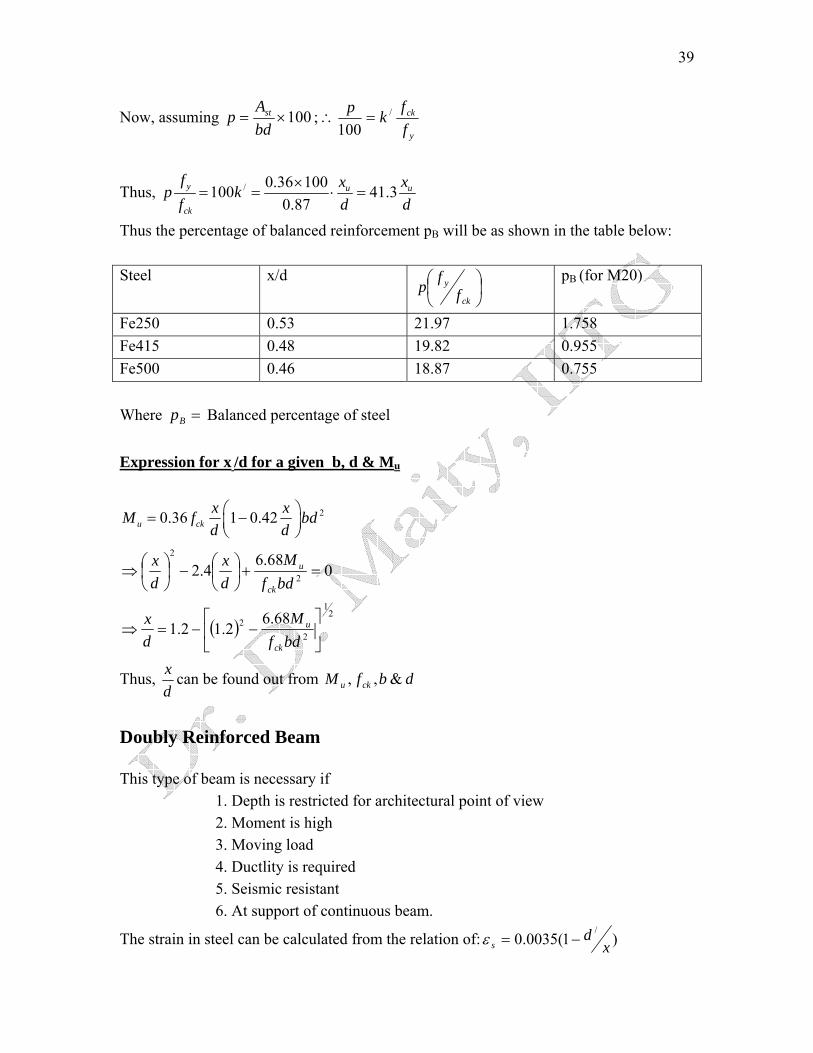
Fe250 0.53 21.97 1.758 Fe415 0.48 19.82 0.955 Fe500 0.46 18.87 0.755 Where Balanced percentage of steel =Bp Expression for x /d for a given b, d & Mu
20.36 1 0.42u ckx xM f bdd d⎛ ⎞= −⎜ ⎟⎝ ⎠
068.6
4.2 2
2
=+⎟⎠⎞
⎜⎝⎛−⎟
⎠⎞
⎜⎝⎛⇒
bdfM
dx
dx
ck
u
( )2
1
22 68.6
2.12.1 ⎥⎦
⎤⎢⎣
⎡−−=⇒
bdfM
dx
ck
u
Thus, dx can be found out from dbfM cku &,,
Doubly Reinforced Beam This type of beam is necessary if
1. Depth is restricted for architectural point of view 2. Moment is high 3. Moving load 4. Ductlity is required 5. Seismic resistant 6. At support of continuous beam.
The strain in steel can be calculated from the relation of: )1(0035.0/
xd
s −=ε
40
Two cases may arise regarding the stress in reinforcement 1. Strain of compression steel is reached at yield strain. 2. Strain of concrete is reached to yield strain of 0.0035 & strain of compression
steel is below of yield strain. Analysis & Design of Doubly Reinforced Beam 1. Strain compatibility method using basic equation. 2. Steel Beam Theory. 3. Use of design aids (SP-16) Strain Compatibility Method Step1: Choose the value of x. Assume the concrete fails at a compressive strain of 0.0035. Then draw the strain distribution of the section. Step2: Calculate strain & corresponding stress in the tensile steel. stst AfT =
Step3: Calculate strain & corresponding stress in the compressive steel. scscs AfC =
Step4: Calculate the compressive force in the concrete block xbfC ckc 36.0=
Step5: Calculate total compressive force as cs CCC +=
Step6: Check if T , then assumed neutral axis depth x is OK. Otherwise choose another suitable x so that T
C=C=
( ) ( )/
2 ddCxkdCM scu −+−=Step7:
41
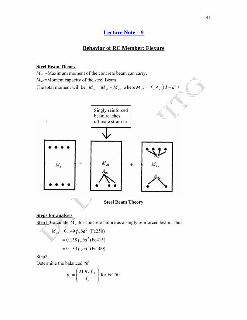
Lecture Note – 9
Behavior of RC Member: Flexure Steel Beam Theory Mu1 =Maximum moment of the concrete beam can carry. Mu2 =Moment capacity of the steel Beam
( )/2 ( ddAfM scscu −=The total moment will be: 21 uuu MMM += where
Steps for analysis Step1: Calculate uM
21 0.149u ck
for con
M f bd= (F
= (20.138 ckf bd
= (20.133 ckf bd
Step2: Determine the balanced “p”
⎜⎜⎝
⎛=
yt f
fp
97.21
Singly reinforcedbeam reaches ultimate strain in
t
Steel Beam Theory
crete failure as a singly reinforced beam. Thus,
e250)
Fe415)
Fe500)
⎟⎟⎠
⎞ck for Fe250
42
⎟⎟⎠
⎞⎜⎜⎝
⎛=
y
ck
ff82.19 for Fe415
⎟⎟⎠
⎞⎜⎜⎝
⎛=
y
ck
ff87.18 for Fe500
1001
bdpA t
st =
Step3: Determine , Then scf scscs AfC =
Step4: Find additional moment, ( )/2u sc scM f A d d= −
=+= M M u2u1uM MStep5: Find total moment from compression failure uc
Step6: Find by tension failure;2stA 12 ststst AAA −=
( )( )/21 87.0 ddfAMM ystuu −+= utM= Step7: Find the total moment by tension failure,
Step8: =uM lesser value of ucM utM &
For given value of Mu, b, d and grade of concrete and steel, find out & scA stA
Step-1. Find 2bdkfM ckul = for concrete failure.
Step-2. Calculate Ast1 considering balanced reinforced section.
( )/
212 87.0 ddAfMMM styuuu −=−=
( )
Step-3. Find
Step-4. Calculate /2
2 87.0 ddfM
Ay
ust −
=
21 ststst AAA +=
∴
Step-5. Find which depends onscf 'dd . Find the corresponding stresses from table F of
SP-16.
Otherwise/
0.0035 1scu
dx
ε⎛ ⎞
= −⎜⎝ ⎠
⎟ . The value of fsc then can be
found from the stress-strain diagram of steel.
43
Step-6. Find ( )
sc
ystsc f
fAA
87.02=
Thus stA & can be found outscA
Design Aids (SP-16)
• Tables are easier than chart • Charts 19 &20 give Ast2 value for (d-d/) and Fe250 only. • For other grade of steel, it is to be modified by table G on page 13 of SP16 • Table (45-56) give values for direct design of doubly reinforced beams.
100×=bdA
p scc
100stt
Apbd
= × where , 21 ststst AAA +=
21 ttt ppp +=
cp & are obtained from the following expression. tp
We know,
))(87.0(100
/2(lim) ddfbd
pMM y
tuu −+=
Or, /(lim) 2
2 2 (0.87 )(1 )100
uu ty
MM p df dbd bd= + −
2(lim)1 ttt ppp
Now,
+=
⎟⎟⎠
⎞⎜⎜⎝
⎛=
sc
ytc f
fpp
87.02 and
Maximum & minimum Tension steel in Beam: Maximum steel
20.87 1100 100
yu y
ck
fp pM f bdf
⎛ ⎞= −⎜ ⎟
⎝ ⎠
Here uM increases with p in a parabolic relation.
For M20 & Fe415, 23.6 0.75uM p p= −

44
From we can have: T C= 0.36 ck st stxf b d f Ad
⎛ ⎞ =⎜ ⎟⎝ ⎠
0.36 100st
ck
fx pd f
⇒ =
For Fe415 & M20: 0.58x pd
⇒ =
Ductility can be measured by curvature.
x
εc
ϕ dθ
εs
1 0.0035Strain in compression fibreR Depth of NA x= =Thus,
1 0.0035 0.006
0.58cd
R dx x pd pdεθφ= = = = =
1p
∝ Thus, Ductility
Hence, though uM increases with the increase of p but ductility (i.e., curvature)
decreases. Hence, IS code (Clause 26.5.1) has put the upper limit of tension & compression steel as 4%. Minimum Steel Minimum steel is required to take care ductility & shrinkage of concrete. As per clause 26.5.1
45
0.85s
y
Abd f
=
for Fe415 0.00205 0.2%= = for Fe250 0.0035 0.35%= = Necessity of minimum steel for shear Clause:26.5.1.6 Minimum steel is necessary to 1. Prevent brittle shear failure, which can occur without shear steel. 2. Guard against any sudden failure of a beam if concrete cover bursts and the bond to the tension is lost. 3. Prevent failure that can be caused by tension due to shrinkage and thermal stresses and internal cracking in the beam. 4. Hold the reinforcements in place while pouring the concrete. 5. Act as the necessary ties for the compression steel and make them effective. Minimum spacing
Asv= total area of stirrups Sv=Spacing b=breadth of web at level of tension
0.40.87
sv
v y
AbS f
=
2.175 vv y
ASS fb
⎛ ⎞= ⎜ ⎟⎝ ⎠
902 vASb
⎛ ⎞⎜ ⎟⎝ ⎠
= for Fe415
544 vASb
⎛ ⎞= ⎜ ⎟⎝ ⎠
for Fe250
Maximum spacing for vertical stirrups 0.75vS d⊄
d ⊄ for inclined ( )045
in any case 300⊄
46
Lecture Note – 10
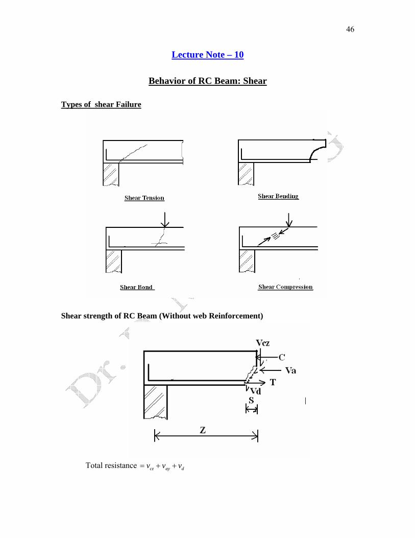
Behavior of RC Beam: Shear Types of shear Failure
Shear strength of RC Beam (Without web Reinforcement)
Total resistance cz ay dv v v= + +
47
Shear in compression zone czv →
Aggregate interlock forces ayv →
Dowel action from longitudinal bars dv →
1. Tensile strength of concrete Affect inclined cracking load 2. Longitudinal reinforcement (p) Restrain cracks 3. Increase in the depth of beam Reduced shear stress at inclined cracking 4. Axial tension Decrease inclined cracking load 5. Axial compression Increase inclined cracking load
Function & strength of web reinforcement Function of web Reinforcement
• Web reinforcement is provided to ensure that the full flexural capacity is developed.
• Acts as ‘clamps’ to keep shear cracks from widening. • Shear resisted by apart from , & . sv czv ayv dv
• increases as cracks widen until yielding of stirrups & then stirrups provide
constant resistant. sv
Flexural Cracking:
Shear is resisted by sdaycz VVVV &,,
Designing to Resist Shear Shear Strength (ACI 318 Sec 11.1)
n uV Vφ ≥ [i.e., Capacity demand] ≥
48
uV factored shear force at section
nV Normal shear strength
φ 0.85(Shear)-strength reduction factor scn VVV +=
cV Normal shear resistance provided by concrete
sV Normal shear provided by the shear reinforcement
Shear Strength Provided by Concrete Bending only Simple formula: dbfV wcc 2 = Eqn [11.3]
dbf wc 3.5 ≤
More detailed:
uc c w w
u
1.9 2500 V dV f p b dM
⎛ ⎞⎛ ⎞= +⎜ ⎟⎜ ⎟⎜ ⎟⎝ ⎠⎝ ⎠
Note 1u
u ≤⎟⎟⎠
⎞⎜⎜
d ⎝
⎛MV
dbf wc 3.5 ≤ Eqn [11.6]
Bending and Axial Compression Simple formula
dbfA
NV wcg
uc
20001 2 ⎟
⎟⎠
⎞⎜⎜⎝
⎛+= Eqn [11.4]
Eqn [11.8] g
uwc 500
1 3.5 A
Ndbf +≤
uN is positive for compression and u
g
NA are in psi.
More detailed
⎟⎠⎞
⎜⎝⎛ −
−=8
4 uumdhNMM Use mM in Eqn [11.6] with no limits
g
uwcc 500
1 3.5 A
NdbfV +≤ Eqn [11.8]
uN is positive for compression and u
g
NA are in psi.
49
Bending and Axial Tension Simple formula V Design shear reinforcement for all shear 0c =
uc c
g
2 1 500
NV fA
⎛ ⎞= +⎜ ⎟⎜ ⎟
⎝ ⎠wb d
uN is negative for tension and u
g
NA are in psi.
Lightweight Concrete: Shear Strength Provided by Shear Reinforcement Minimum Shear Reinforcement: (11.5.5)
Required when cu VV 21 φ≥
Except: (a)Slabs & Footings (b)Concrete Joist Construction (defined 8.11)
(c )Beams with h ≤ larger of ⎪⎩
⎪⎨
⎧
w
f
b 1/2 t2.5
10"
50
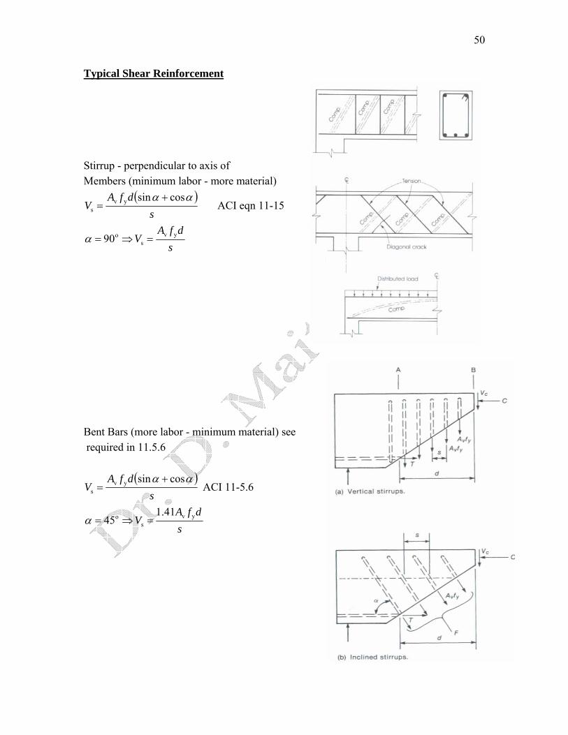
Typical Shear Reinforcement Stirrup - perpendicular to axis of Members (minimum labor - more material)
( )s
dfAV
αα cossinyvs
+= ACI eqn 11-15
sdfA
V yvs
o90 =⇒=α
Bent Bars (more labor - minimum material) see required in 11.5.6
( )s
dfAV
αα cossinyvs
+= ACI 11-5.6
sdfA
V yvs
o 41.145 =⇒=α
51
Design Procedure for Shear 1. Calculate uV
2. Calculate Eqn 11-3 or 11-5 (no axial force) cVφ
3. Check If yes, add web reinforcement (go to 4)
If no, done ⎩⎨⎧
→φ≥ cu VV21
4. →φ≤≤φ cuc VVV21 If Provide minimum shear reinforcement
( ) ⎟⎟⎠
⎞⎜⎜⎝
⎛== v
w
ysv
y
wv A
bfA
sf
sbA min for 50
or 50 maxmin
Also done
max 24"2ds ≤ ≤ (11.5.4)
5. If uV Vcφ≥ , calculate sV (required)
u n cV V V Vsφ φ φ≤ = +
us u c s c
VV V V V Vφ φφ
⇒ = − ⇒ = −
Check, 8 s c w b d′≤V f (otherwise illegal) (11.5.4)
6. Solve for required stirrup spacing (strength) Assume # 3, #4, or #5 stirrups
v ys
s
A f ds
V≤ from 11-15
7. Check minimum steel requirement (eqn 11-13) max 50v ys
w
A fs
b=
8. Check maximum spacing requirement (ACI 11.5.4)
c max4 24"2s wdb d s′≤ → ≤ ≤V f If
If c max4 124s wd "b d s′≥ → ≤ ≤V f Note: c8 s wb d′≥V f (Illegal)
9. Use smallest spacing from steps 6,7,8 Note: A practical limit to minimum stirrup spacing is 4 inches.
52
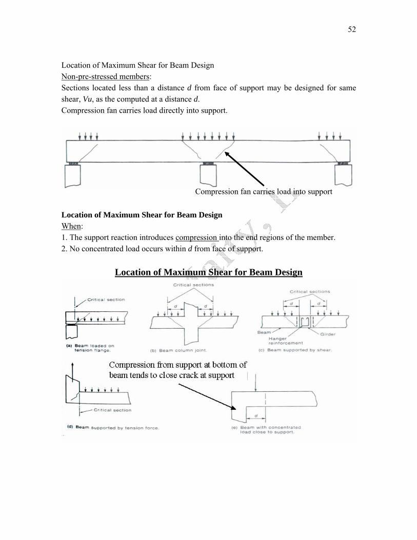
Location of Maximum Shear for Beam Design Non-pre-stressed members: Sections located less than a distance d from face of support may be designed for same shear, Vu, as the computed at a distance d. Compression fan carries load directly into support.
Compression fan carries load into support Location of Maximum Shear for Beam Design When: 1. The support reaction introduces compression into the end regions of the member. 2. No concentrated load occurs within d from face of support.
Location of Maximum Shear for Beam Design


![CONTINUITY, CURVATURE, AND THE GENERAL · PDF fileCONTINUITY, CURVATURE, AND OPTIMAL TRANSPORTATION 3 [41] [42]. Loeper furthermore offered a direct argument giving an explicit H¨older](https://static.fdocument.org/doc/165x107/5a7991c97f8b9ade698cfe20/continuity-curvature-and-the-general-curvature-and-optimal-transportation.jpg)