Lecture 5 Plane Wave Reflection and Transmission · PDF fileReflection and Transmission ......
25
Lecture 5 Plane Wave Reflection and Transmission
-
Upload
nguyendung -
Category
Documents
-
view
215 -
download
0
Transcript of Lecture 5 Plane Wave Reflection and Transmission · PDF fileReflection and Transmission ......
Lecture 5
Plane Wave Reflection and Transmission
1
1
1
ˆ( ) (0)1ˆ( ) (0)
zr r
zr r
z E e
z E e
E x
H y
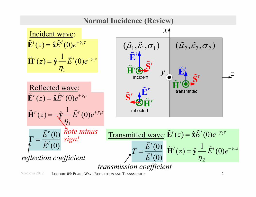
Normal Incidence (Review)
Incident wave:1
1
1
ˆ( ) (0)1ˆ( ) (0)
zi i
zi i
z E e
z E e
E x
H y
Reflected wave:
Transmitted wave: 2
2
2
ˆ( ) (0)1ˆ( ) (0)
zt t
zt t
z E e
z E e
E x
H y
1 1 1( , , ) 2 2 2( , , )
x
y z
iE
rE
tEiH
rH
tH
iStS
rS
Nikolova 2012 2LECTURE 05: PLANE WAVE REFLECTION AND TRANSMISSION
(0)(0)
r
iEE
reflection coefficient(0)(0)
t
iETE
transmission coefficient
note minus sign!
Nikolova 2012 3
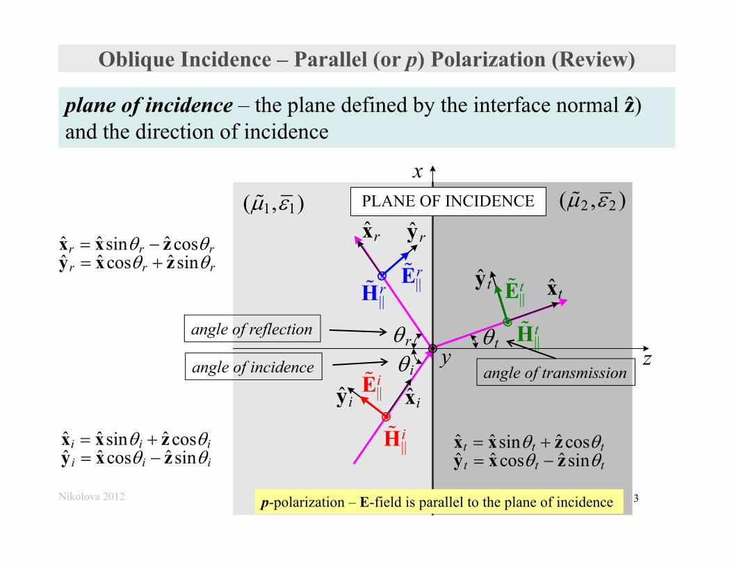
Oblique Incidence – Parallel (or p) Polarization (Review)
plane of incidence – the plane defined by the interface normal ẑ) and the direction of incidence
x
zy
1 1( , ) 2 2( , )
ˆ ixˆ iy ||iE
||iH
ir t
ˆ ryˆ rx
||rE
||rH ˆ txˆ ty
||tE
||tH
PLANE OF INCIDENCE
angle of incidence
angle of reflection
angle of transmission
ˆ ˆ ˆsin cosˆ ˆ ˆcos sin
r r rr r r
x x zy x z
ˆ ˆ ˆsin cosˆ ˆ ˆcos sin
i i ii i i
x x zy x z
ˆ ˆ ˆsin cosˆ ˆ ˆcos sin
t t tt t t
x x zy x z
p-polarization – E-field is parallel to the plane of incidence
Nikolova 2012 4LECTURE 05: PLANE WAVE REFLECTION AND TRANSMISSION
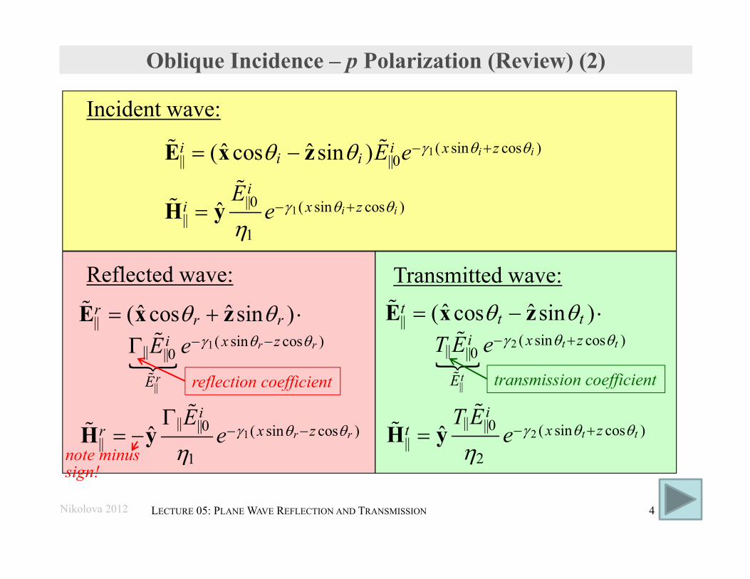
Oblique Incidence – p Polarization (Review) (2)
Incident wave:
1
1
( sin cos )|| ||0
||0 ( sin cos )||
1
ˆ ˆ( cos sin )
ˆ
i i
i i
i i x zi i
ii x z
E e
Ee
E x z
H y
Reflected wave:
1
||
||( sin cos )
|| ||0
ˆ ˆ( cos sin ) r r
r
rr r
i x z
E
E e
E x z
Transmitted wave:
2
||
||( sin cos )
|| ||0
ˆ ˆ( cos sin ) t t
t
tt t
i x z
E
T E e
E x z
1|| ||0 ( sin cos )
||1
ˆ r r
ir x z
Ee
H y
2
|| ||0 ( sin cos )||
2ˆ t t
it x z
T Ee
H y
reflection coefficient transmission coefficient
note minus sign!
Nikolova 2012 5LECTURE 05: PLANE WAVE REFLECTION AND TRANSMISSION
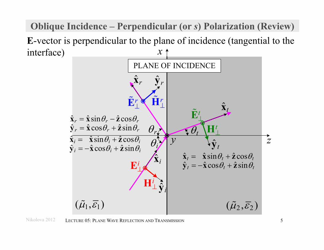
Oblique Incidence – Perpendicular (or s) Polarization (Review)E-vector is perpendicular to the plane of incidence (tangential to the interface) x
zy
1 1( , ) 2 2( , )
ˆ ix
ˆ iy
iE
iH
ir t
ˆ ryˆ rx
rE r
H ˆ tx
ˆ ty
tE
tH
ˆ ˆ ˆsin cosˆ ˆ ˆcos sin
r r r
r r r
x x zy x zˆ ˆ ˆsin cosˆ ˆ ˆcos sin
i i i
i i i
x x zy x z
ˆ ˆ ˆsin cosˆ ˆ ˆcos sin
t t t
t t t
x x zy x z
Nikolova 2012 6LECTURE 05: PLANE WAVE REFLECTION AND TRANSMISSION
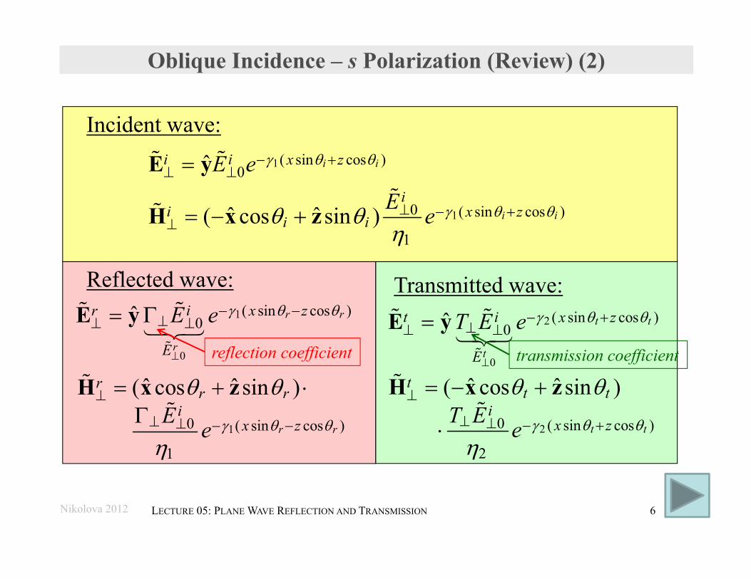
Oblique Incidence – s Polarization (Review) (2)
Incident wave:1
1
( sin cos )0
0 ( sin cos )
1
ˆ
ˆ ˆ( cos sin )
i i
i i
i i x z
ii x z
i i
E e
E e
E y
H x z
Reflected wave:
10 ( sin cos )
1
ˆ ˆ( cos sin )
r r
rr r
ix zE e
H x z
Transmitted wave:
20 ( sin cos )
2
ˆ ˆ( cos sin )
t t
tt t
ix zT E e
H x z
1
0
( sin cos )0ˆ r r
r
ir x z
E
E e
E y
2
0
( sin cos )0ˆ t t
t
t i x z
E
T E e
E y
reflection coefficient transmission coefficient
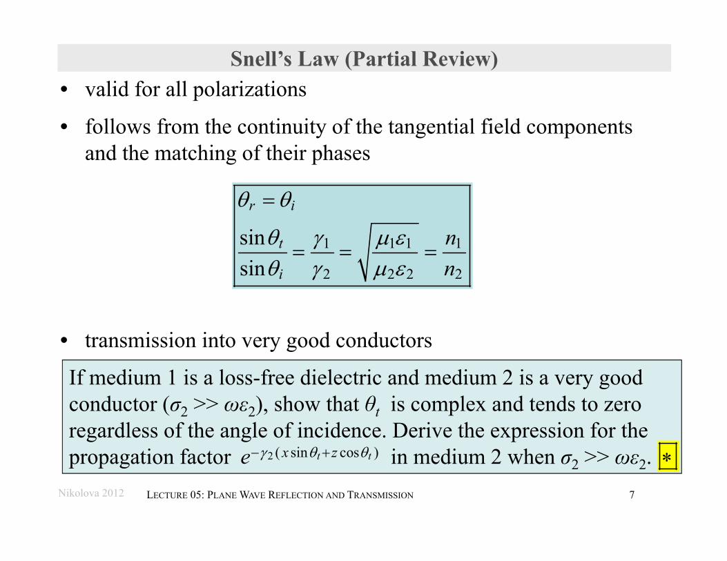
• valid for all polarizations
• follows from the continuity of the tangential field components and the matching of their phases
• transmission into very good conductors
Nikolova 2012 7LECTURE 05: PLANE WAVE REFLECTION AND TRANSMISSION
Snell’s Law (Partial Review)
1 1 1 1
2 2 2 2
sinsin
r i
t
i
nn
If medium 1 is a loss-free dielectric and medium 2 is a very good conductor (σ2 >> ωε2), show that θt is complex and tends to zero regardless of the angle of incidence. Derive the expression for the propagation factor in medium 2 when σ2 >> ωε2. 2 ( sin cos )t tx ze
Nikolova 2012 8LECTURE 05: PLANE WAVE REFLECTION AND TRANSMISSION
Reflection and Transmission (Fresnel) Coefficients (Review)
• by definition the reflection coefficient Γ gives the ratio of the reflected to incident tangential E-field component at the interface
• the ratio of the reflected to incident tangential H-field component at the interface is −Γ
• by definition the transmission coefficient T gives the ratio of the transmitted to incident tangential E-field component at the interface
Nikolova 2012 9LECTURE 05: PLANE WAVE REFLECTION AND TRANSMISSION
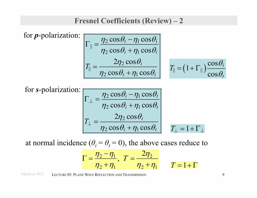
Fresnel Coefficients (Review) – 2
2 1||
2 1
2||
2 1
cos coscos cos
2 coscos cos
t i
t i
i
t iT
at normal incidence (θi = θt = 0), the above cases reduce to 2 1 2
2 1 2 1
2,
|| ||cos1cos
i
tT
for p-polarization:
for s-polarization:2 1
2 1
2
2 1
cos coscos cos
2 coscos cos
i t
i t
i
i tT
1T
1T
Nikolova 2012 10LECTURE 05: PLANE WAVE REFLECTION AND TRANSMISSION
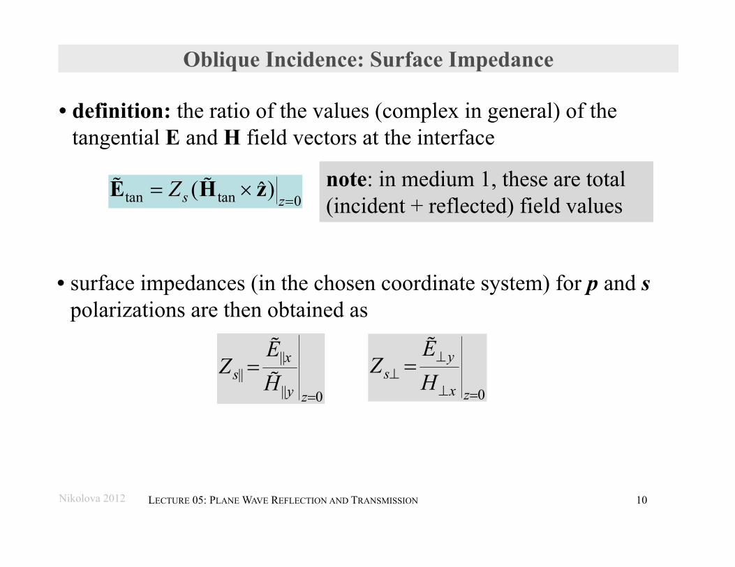
Oblique Incidence: Surface Impedance
• surface impedances (in the chosen coordinate system) for p and spolarizations are then obtained as
tan tan 0( )ˆs z
Z
E H z
||||
|| 0
xs
y z
EZ
H
0
ys
x z
EZ
H
• definition: the ratio of the values (complex in general) of the tangential E and H field vectors at the interface
note: in medium 1, these are total (incident + reflected) field values
Nikolova 2012 11LECTURE 05: PLANE WAVE REFLECTION AND TRANSMISSION
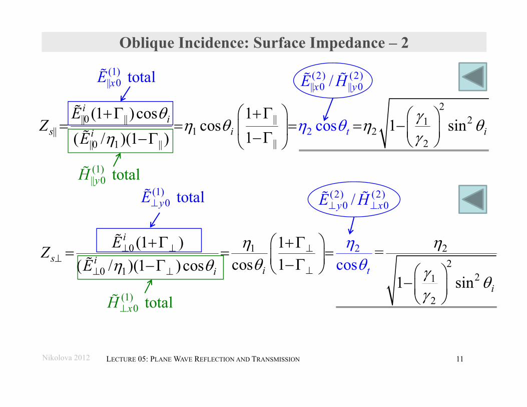
Oblique Incidence: Surface Impedance – 2
2||0 || || 21
|| 1 2|| 2||0 1 ||
2(1 )cos 1
cos 1 sin1( /
c s)(1 )
oi
its i ii
EZ
E
20 1 22
0 1 21
2
(1 ) 1 =cos 1( / )(1 )cos co
ins
1 s
i
sii t
i
i
EZE
(1)|| 0 totalyH
(1)|| 0 totalxE (2) (2)
|| 0 || 0/x yE H
(1)0 totalyE
(1)0 totalxH
(2) (2)0 0/y xE H
Nikolova 2012 12LECTURE 05: PLANE WAVE REFLECTION AND TRANSMISSION
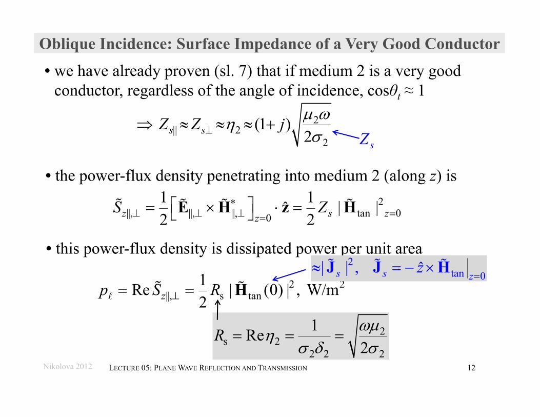
Oblique Incidence: Surface Impedance of a Very Good Conductor
• the power-flux density penetrating into medium 2 (along z) is2
||, ||, ||, tan 00
1 1 | |ˆ2 2z s zz
S Z
E H z H
• this power-flux density is dissipated power per unit area
2 2||, s tan
1Re | (0) | , W/m2zp S R H
• we have already proven (sl. 7) that if medium 2 is a very good conductor, regardless of the angle of incidence, cosθt ≈ 1
2s 2
2 2 2
1Re2
R
2|| 2
2 (1 )
2s sZ Z j
sZ
2tan 0| | , ˆs s zz
J J H
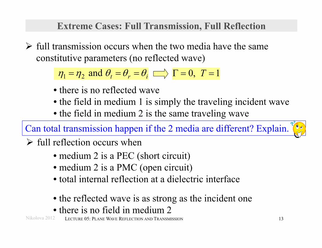
Extreme Cases: Full Transmission, Full Reflection
full transmission occurs when the two media have the same constitutive parameters (no reflected wave)
1 2 and t r i 0, 1T
full reflection occurs when
Nikolova 2012 13LECTURE 05: PLANE WAVE REFLECTION AND TRANSMISSION
• medium 2 is a PEC (short circuit)• medium 2 is a PMC (open circuit)• total internal reflection at a dielectric interface
• there is no reflected wave• the field in medium 1 is simply the traveling incident wave• the field in medium 2 is the same traveling wave
• the reflected wave is as strong as the incident one• there is no field in medium 2
Can total transmission happen if the 2 media are different? Explain.
Full Reflection
Nikolova 2012 14LECTURE 05: PLANE WAVE REFLECTION AND TRANSMISSION
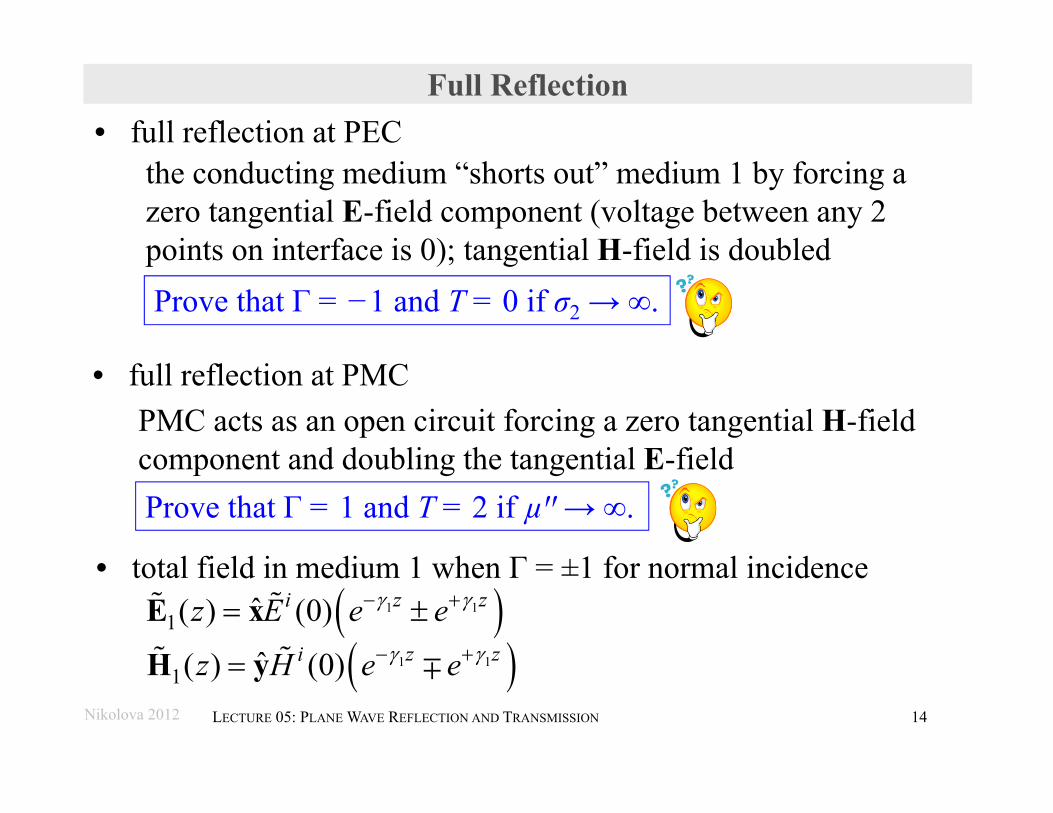
Prove that Γ = −1 and T = 0 if σ2 → ∞.
the conducting medium “shorts out” medium 1 by forcing a zero tangential E-field component (voltage between any 2 points on interface is 0); tangential H-field is doubled
• total field in medium 1 when Γ = ±1 for normal incidence
1 1
1 1
1
1
ˆ( ) (0)
ˆ( ) (0)
z zi
z zi
z E e e
z H e e
E x
H y
• full reflection at PEC
• full reflection at PMCPMC acts as an open circuit forcing a zero tangential H-field component and doubling the tangential E-fieldProve that Γ = 1 and T = 2 if µꞌꞌ→ ∞.
tan
2 2 2s tan s tan
2 (0)
0.5 | (0) | | (0) | , W/mi
i
H
p R R H H
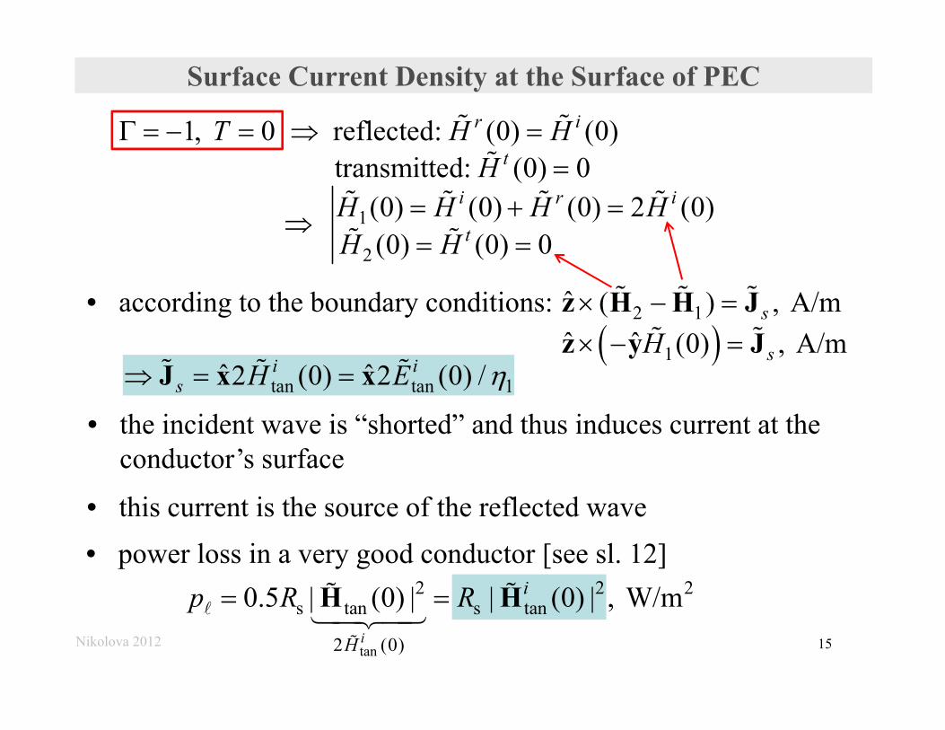
Surface Current Density at the Surface of PEC
1
2
1, 0 reflected: (0) (0) transmitted: (0) 0
(0) (0) (0) 2 (0) (0) (0) 0
r i
t
i r i
t
T H HH
H H H HH H
• according to the boundary conditions:
2 1
1
ˆ ( ) , A/mˆ ˆ (0) , A/m
s
sH
z H H Jz y J
tan tan 1ˆ ˆ2 (0) 2 (0) /i is H E J x x
• the incident wave is “shorted” and thus induces current at the conductor’s surface
• this current is the source of the reflected wave
Nikolova 2012 15
• power loss in a very good conductor [see sl. 12]
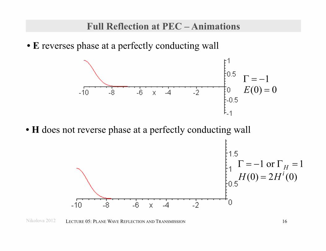
Full Reflection at PEC – Animations
• E reverses phase at a perfectly conducting wall
• H does not reverse phase at a perfectly conducting wall
Nikolova 2012 16LECTURE 05: PLANE WAVE REFLECTION AND TRANSMISSION
1(0) 0E
1 or 1(0) 2 (0)
HiH H
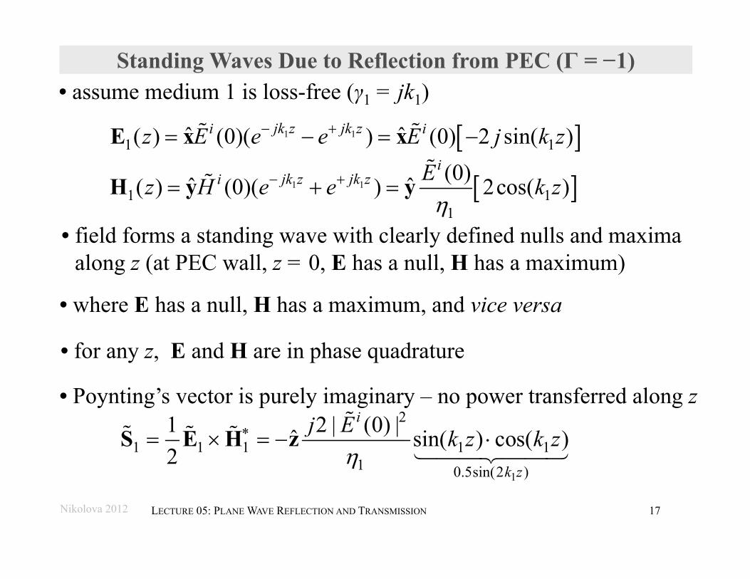
Standing Waves Due to Reflection from PEC (Γ = −1)
1 11 1ˆ ˆ( ) (0)( ) (0) 2 sin( )jk z jk zi iz E e e E j k z E x x
1 11 1
1
(0)ˆ ˆ( ) (0)( ) 2cos( )i
jk z jk zi Ez H e e k z
H y y
• assume medium 1 is loss-free (γ1 = jk1)
1
2
1 1 1 1 11 0.5sin(2 )
1 2 | (0) |ˆ sin( ) cos( )2
i
k z
j E k z k z
S E H z
• field forms a standing wave with clearly defined nulls and maxima along z (at PEC wall, z = 0, E has a null, H has a maximum)
• Poynting’s vector is purely imaginary – no power transferred along z
• where E has a null, H has a maximum, and vice versa
Nikolova 2012 17LECTURE 05: PLANE WAVE REFLECTION AND TRANSMISSION
• for any z, E and H are in phase quadrature
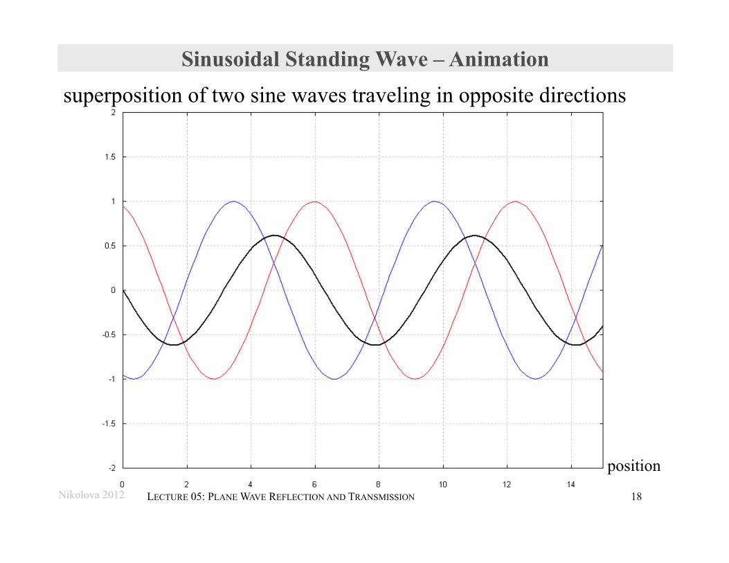
Sinusoidal Standing Wave – Animation superposition of two sine waves traveling in opposite directions
Nikolova 2012 18LECTURE 05: PLANE WAVE REFLECTION AND TRANSMISSION
position
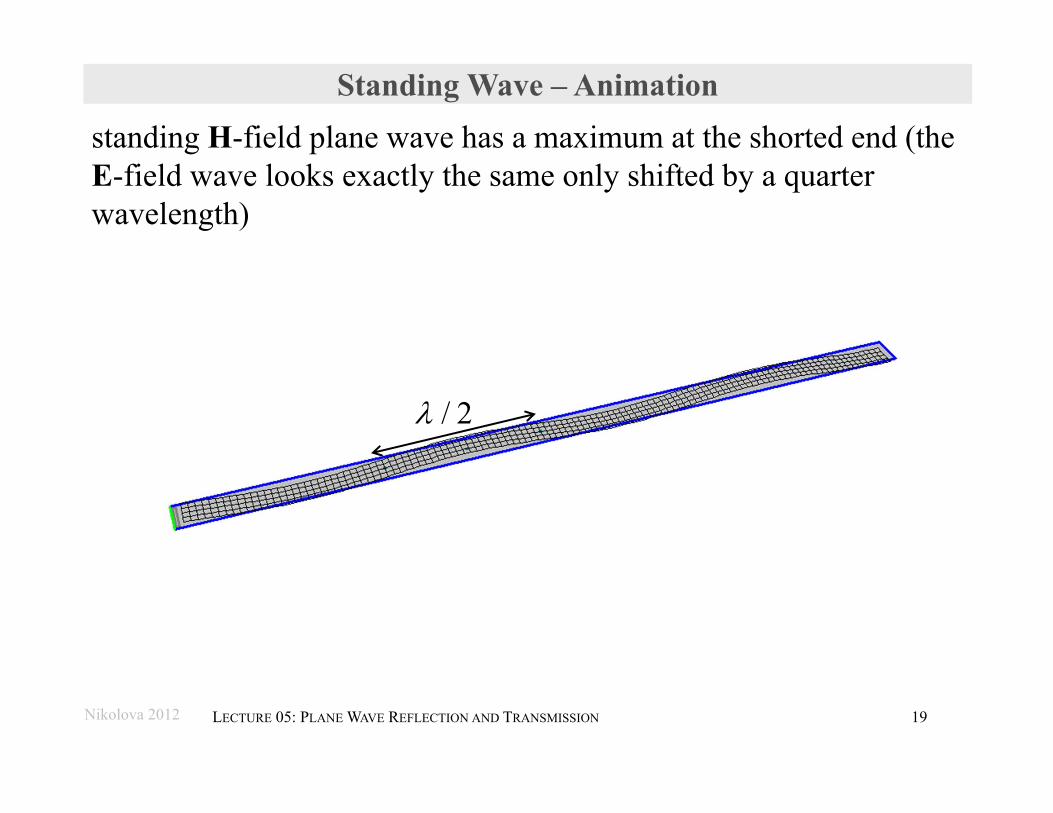
Standing Wave – Animation standing H-field plane wave has a maximum at the shorted end (the E-field wave looks exactly the same only shifted by a quarter wavelength)
Nikolova 2012 19LECTURE 05: PLANE WAVE REFLECTION AND TRANSMISSION
/ 2
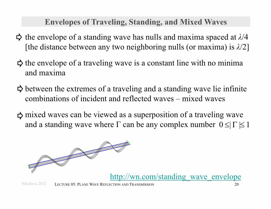
Envelopes of Traveling, Standing, and Mixed Waves
the envelope of a standing wave has nulls and maxima spaced at λ/4[the distance between any two neighboring nulls (or maxima) is λ/2]
the envelope of a traveling wave is a constant line with no minima and maxima
between the extremes of a traveling and a standing wave lie infinite combinations of incident and reflected waves – mixed waves
mixed waves can be viewed as a superposition of a traveling wave and a standing wave where Γ can be any complex number
Nikolova 2012 20LECTURE 05: PLANE WAVE REFLECTION AND TRANSMISSION
0 | | 1
http://wn.com/standing_wave_envelope
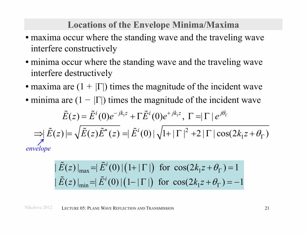
Locations of the Envelope Minima/Maxima• maxima occur where the standing wave and the traveling wave
interfere constructively• minima occur where the standing wave and the traveling wave
interfere destructively• maxima are (1 + |Γ|) times the magnitude of the incident wave• minima are (1 − |Γ|) times the magnitude of the incident wave
1 1( ) (0) (0) , | |jk z jk z ji iE z E e E e e 2
1| ( ) | ( ) ( ) | (0) | 1 | | 2 | | cos(2 )iE z E z E z E k z
max 1
min 1
| ( ) | | (0) | 1 | | for cos(2 ) 1| ( ) | | (0) | 1 | | for cos(2 ) 1
i
i
E z E k zE z E k z
Nikolova 2012 21LECTURE 05: PLANE WAVE REFLECTION AND TRANSMISSION
envelope
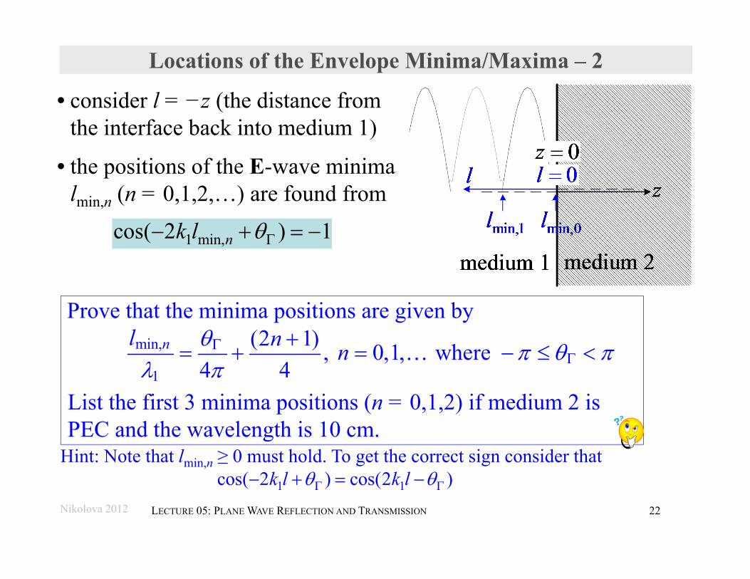
Locations of the Envelope Minima/Maxima – 2
1 min,cos( 2 ) 1nk l
min,
1
(2 1) , 0,1, where 4 4
nl n n
Nikolova 2012 22LECTURE 05: PLANE WAVE REFLECTION AND TRANSMISSION
• consider l = −z (the distance from the interface back into medium 1)
• the positions of the E-wave minima lmin,n (n = 0,1,2,…) are found from
Prove that the minima positions are given by
List the first 3 minima positions (n = 0,1,2) if medium 2 is PEC and the wavelength is 10 cm.
Hint: Note that lmin,n ≥ 0 must hold. To get the correct sign consider that1 1cos( 2 ) cos(2 )k l k l
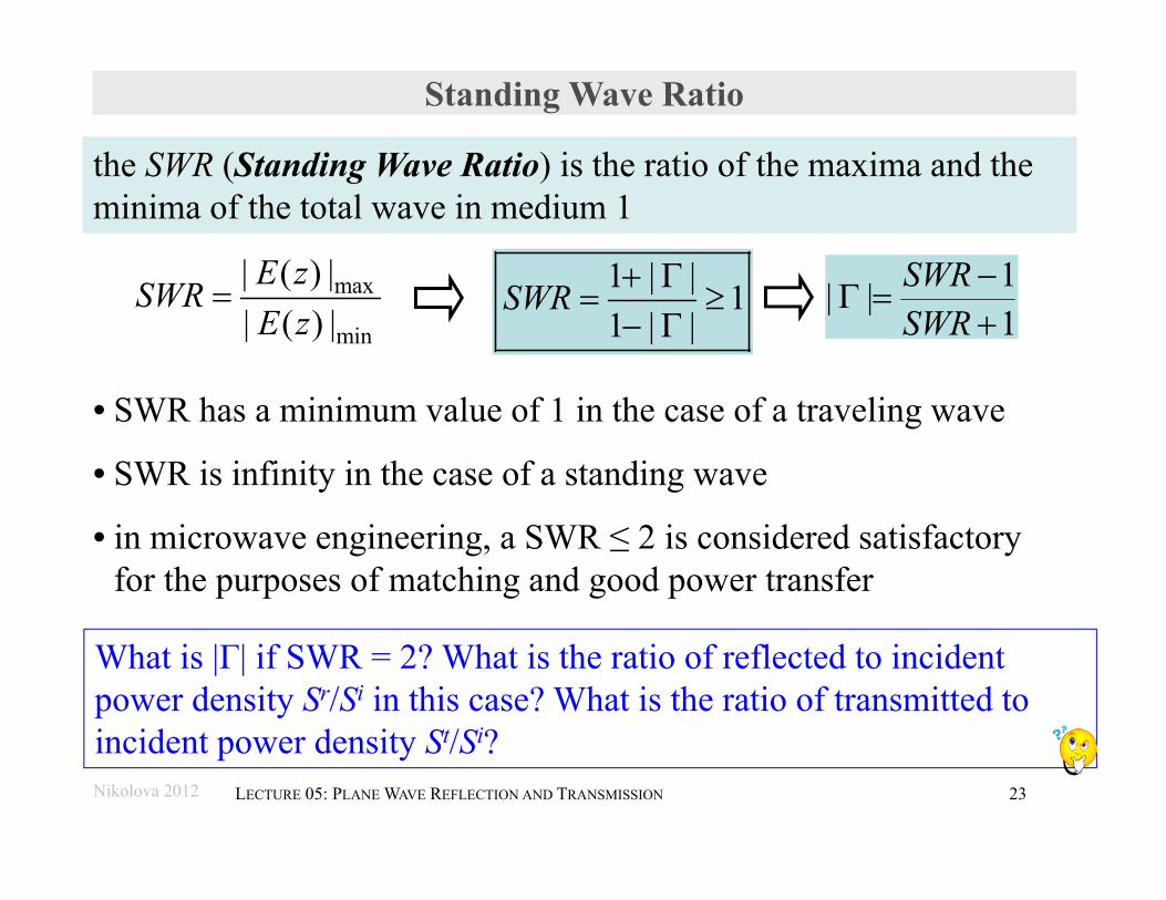
Standing Wave Ratio
• SWR has a minimum value of 1 in the case of a traveling wave
• SWR is infinity in the case of a standing wave
• in microwave engineering, a SWR ≤ 2 is considered satisfactory for the purposes of matching and good power transfer
the SWR (Standing Wave Ratio) is the ratio of the maxima and the minima of the total wave in medium 1
1 | | 11 | |
SWR
max
min
| ( ) || ( ) |E zSWRE z
What is |Γ| if SWR = 2? What is the ratio of reflected to incident power density Sr/Si in this case? What is the ratio of transmitted to incident power density St/Si?
1| |1
SWRSWR
Nikolova 2012 23LECTURE 05: PLANE WAVE REFLECTION AND TRANSMISSION
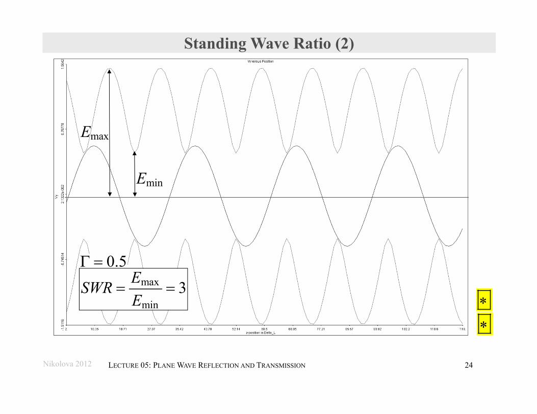
Standing Wave Ratio (2)
0.5
maxE
minE
max
min3ESWR
E
Nikolova 2012 24LECTURE 05: PLANE WAVE REFLECTION AND TRANSMISSION
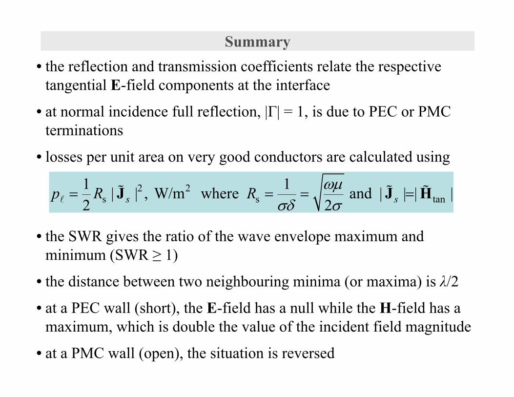
Summary• the reflection and transmission coefficients relate the respective
tangential E-field components at the interface
• at normal incidence full reflection, |Γ| = 1, is due to PEC or PMC terminations
• losses per unit area on very good conductors are calculated using
• the SWR gives the ratio of the wave envelope maximum and minimum (SWR ≥ 1)
• the distance between two neighbouring minima (or maxima) is λ/2
• at a PEC wall (short), the E-field has a null while the H-field has a maximum, which is double the value of the incident field magnitude
• at a PMC wall (open), the situation is reversed
2 2s s tan
1 1| | , W/m where and | | | |2 2s sp R R
J J H