Lecture 40 Turbulent Flow in Pipe
9
NPTEL , IIT Kharagpur, Prof. Saikat Chakraborty, Department of Chemical Engineering 1 Module 5: Mass transfer in turbulant flows Lecture 40: Turbulent Flow in a Pipe
Transcript of Lecture 40 Turbulent Flow in Pipe
NPTEL , IIT Kharagpur, Prof. Saikat Chakraborty, Department of Chemical Engineering
1
Module 5:
Mass transfer in turbulant flows
Lecture 40:
Turbulent Flow in a Pipe
NPTEL , IIT Kharagpur, Prof. Saikat Chakraborty, Department of Chemical Engineering
2
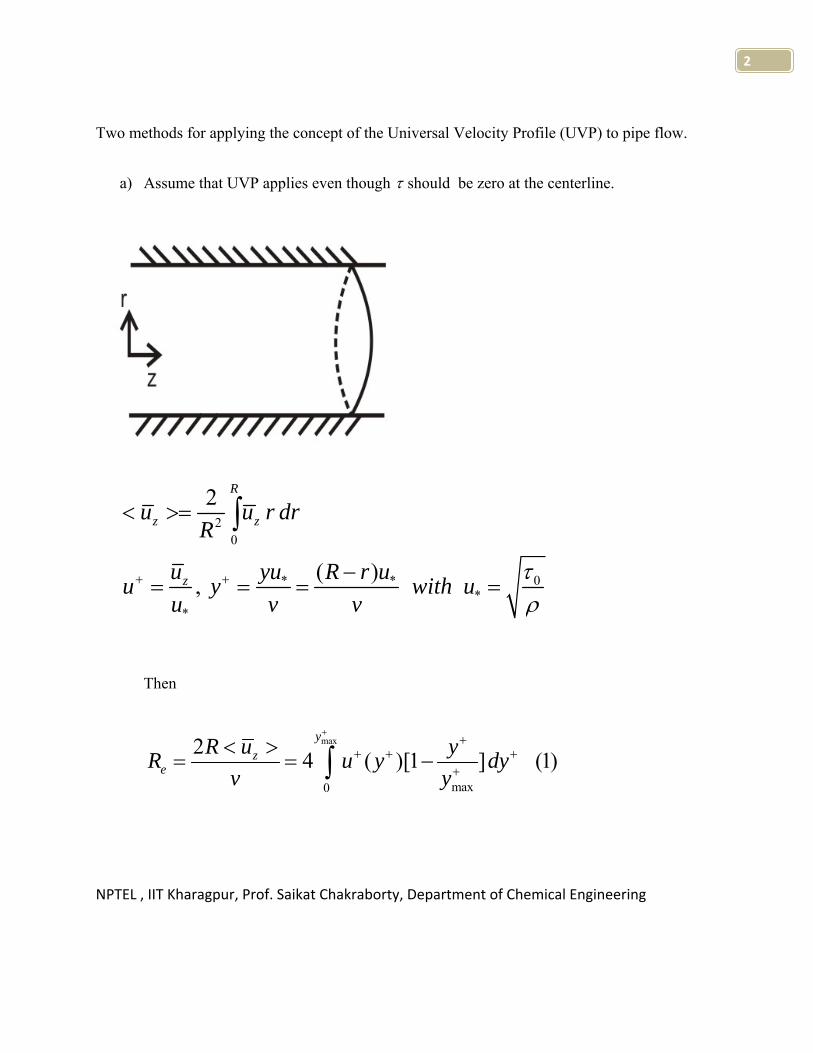
Two methods for applying the concept of the Universal Velocity Profile (UVP) to pipe flow.
a) Assume that UVP applies even though τ should be zero at the centerline.
Then
max
max0
2 4 ( )[1 ] (1)y
ze
R u yR u y dyv y
++
+ + ++
< >= = −∫
20
0* **
*
2
( ),
R
z z
z
u u r drR
u yu R r uu y with uu v v
τρ
+ +
< >=
−= = = =
∫
NPTEL , IIT Kharagpur, Prof. Saikat Chakraborty, Department of Chemical Engineering
3
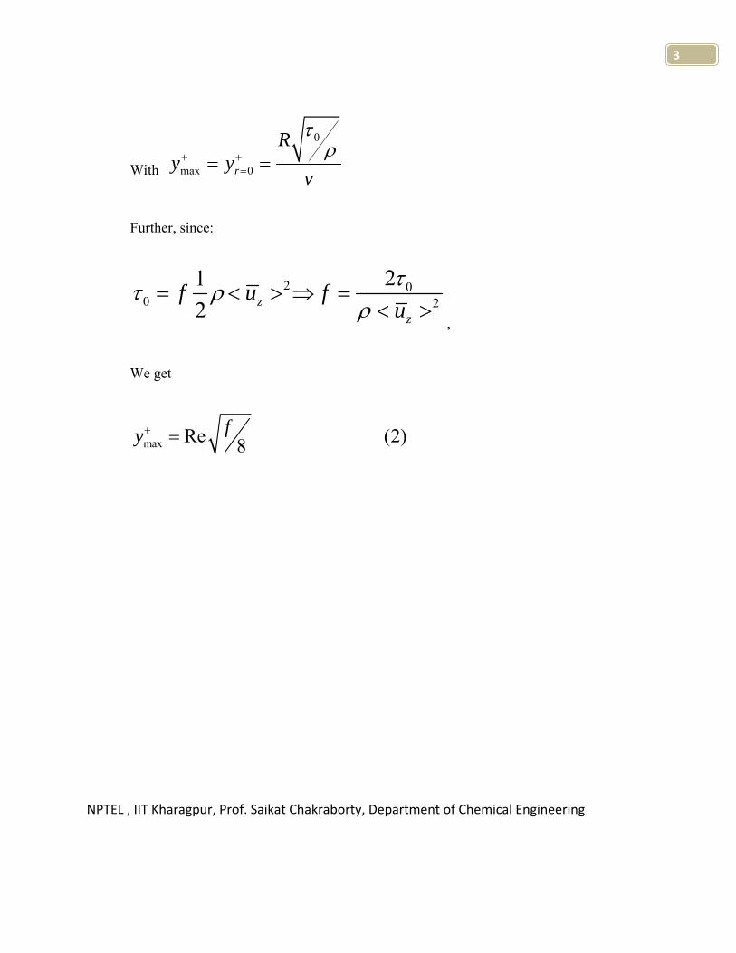
With
0
max 0r
Ry y
v
τρ+ +
== =
Further, since:
2 00 2
212 z
z
f u fuττ ρ
ρ= < > ⇒ =
< >,
We get
max Re (2)8fy+ =
NPTEL , IIT Kharagpur, Prof. Saikat Chakraborty, Department of Chemical Engineering
4
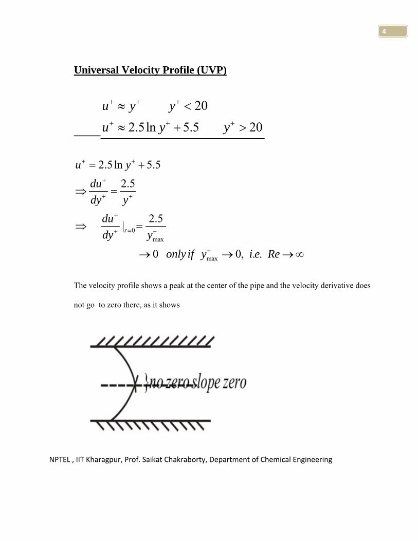
Universal Velocity Profile (UVP)
202.5ln 5.5 20
u y yu y y
+ + +
+ + +
≈ <
≈ + >
0max
max
2.5ln 5.52.5
2.5|
0 0, . .
r
u ydudy y
dudy y
only if y i e Re
+ +
+
+ +
+
=+ +
+
= +
⇒ =
⇒ =
→ → →∞
The velocity profile shows a peak at the center of the pipe and the velocity derivative does
not go to zero there, as it shows

NPTEL , IIT Kharagpur, Prof. Saikat Chakraborty, Department of Chemical Engineering
5
0rzrR
τ τ=
Given Re, use UVP and eq. (1) to find ymax+ and find f from eq. (2).
4 4max
4 4 5 5 6 6 7
3
3exp.
116 315 815 2366 6349 1.6 10 5.2 10 1.58
Re 3000 10 3.10 10 3.10 10 3.10 10
10 12.01 7.96 5.91 4.48 3.58 2.88 2.40 1.99
10 11 7.6 5.8 4.5 3.5 2.8 2.4 2.00
y
f
f
+ × ×
Now, for pipe flow (for both turbulent and laminar flow)
( )( )
0
( )
max
( )( )
(1 ) 1
tt z
rz
t
u dur dy
du r ydy R y
μ μτ μ μ τμ
μμ
+
+
+ +
+ +
∂ += − + = ⇒
∂
+ = = −
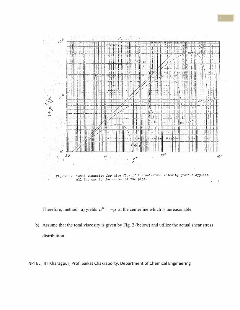
See Figure 1 below.
NPTEL , IIT Kharagpur, Prof. Saikat Chakraborty, Department of Chemical Engineering
6
Therefore, method a) yields ( )tμ μ= − at the centerline which is unreasonable.
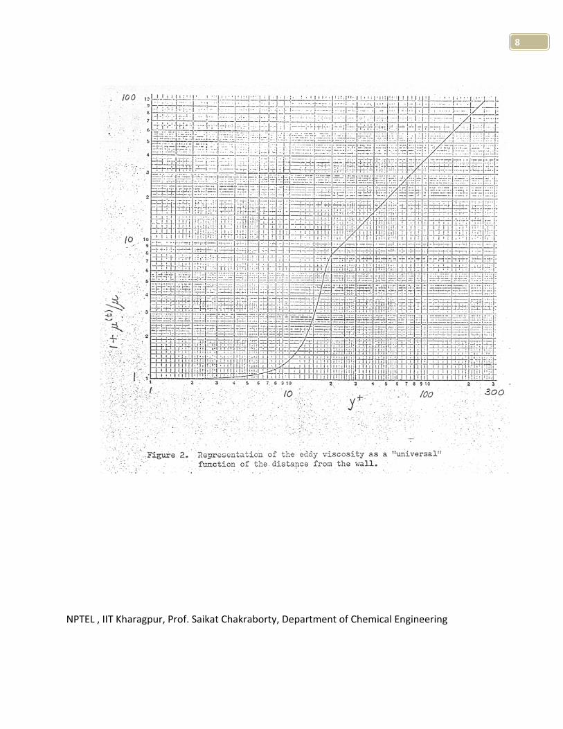
b) Assume that the total viscosity is given by Fig. 2 (below) and utilize the actual shear stress
distribution
NPTEL , IIT Kharagpur, Prof. Saikat Chakraborty, Department of Chemical Engineering
7
( )max
( )max 0
1(1 ) 1
1
yt
t
yydu y u dy
dy yμ
μμμ
+
+
++ ++
+ +
−+ = − ⇒ =
+∫
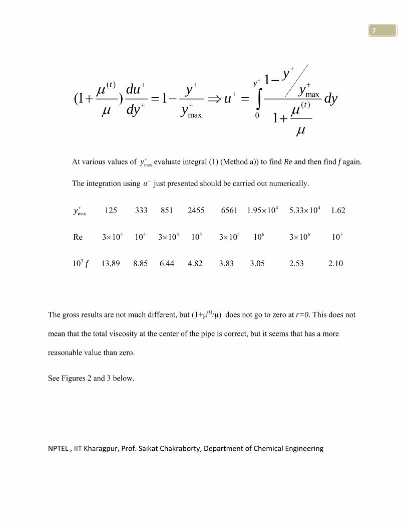
At various values of maxy+ evaluate integral (1) (Method a)) to find Re and then find f again.
The integration using u + just presented should be carried out numerically.
4 4max
3 4 4 5 5 6 6 7
3
125 333 851 2455 6561 1.95 10 5.33 10 1.62
Re 3 10 10 3 10 10 3 10 10 3 10 10
10 13.89 8.85 6.44 4.82 3.83 3.05 2.53 2.10
y
f
+ × ×
× × × ×
The gross results are not much different, but (1+μ(t)/μ) does not go to zero at r=0. This does not
mean that the total viscosity at the center of the pipe is correct, but it seems that has a more
reasonable value than zero.
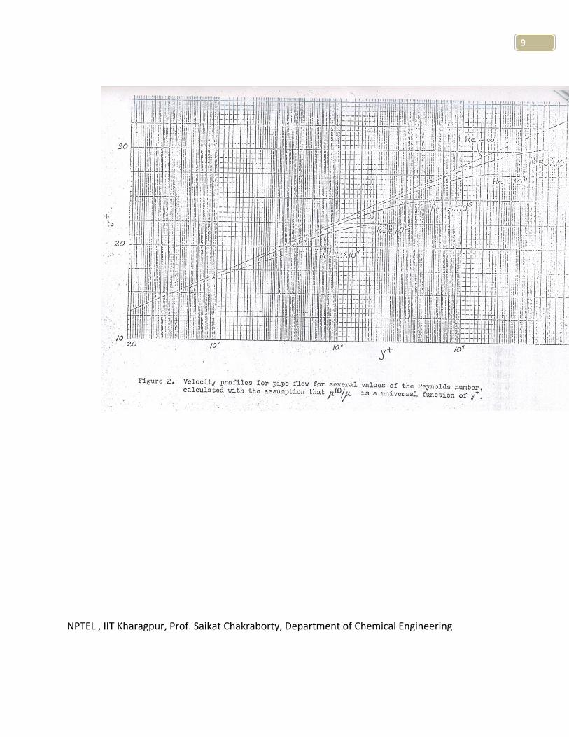
See Figures 2 and 3 below.
NPTEL , IIT Kharagpur, Prof. Saikat Chakraborty, Department of Chemical Engineering
8
NPTEL , IIT Kharagpur, Prof. Saikat Chakraborty, Department of Chemical Engineering
9