Lecture -1 Steel Structures Design Philosophies
67
N-W.F.P. University of Engineering and Technology Peshawar 1 Steel Structures CE-409 By: Prof Dr. Akhtar Naeem Khan [email protected]
description
steel structure
Transcript of Lecture -1 Steel Structures Design Philosophies

N-W.F.P. University of Engineering and Technology
Peshawar
1
Steel Structures CE-409
By: Prof Dr. Akhtar Naeem [email protected]
CE-411: Lecture 01 Prof. Dr Akhtar Naeem Khan
2
Course Content
Design philosophies
Introduction to Steel Structures
Design of Welded connections
Design of Bolted connections
Design of Tension Members
Design of Compression Members
CE-411: Lecture 01 Prof. Dr Akhtar Naeem Khan
3
Course Content
Design of Column Bases
Design of Beams
Design of Composite Beams
Design of Plate Girders

N-W.F.P. University of Engineering and Technology
Peshawar
4
By: Prof Dr. Akhtar Naeem [email protected]
Lecture 01: Design Philosophies
CE-411: Lecture 01 Prof. Dr Akhtar Naeem Khan
5
Topics to be coveredDesign philosophies
Limit States
Design Considerations
Allowable Stress Design (ASD)
Load and Resistance Factor Design (LRFD)
Design process

CE-411: Lecture 01 Prof. Dr Akhtar Naeem Khan
6
Design Philosophies
A general statement assuming safety in
engineering design is:
Resistance ≥ Effect of applied loads ---(1)
In eq(1) it is essential that both sides are
evaluated for same conditions and units e.g.
compressive stress on soil should be
compared with bearing capacity of soil

CE-411: Lecture 01 Prof. Dr Akhtar Naeem Khan
7
Design PhilosophiesResistance of structures is composed
of its members which comes from
materials & X-section
Resistance, Capacity, and Strength are
somewhat synonym terms.
Terms like Demand, Stresses, and
Loads are used to express Effect of
applied loads.

CE-411: Lecture 01 Prof. Dr Akhtar Naeem Khan
8
Limit StatesWhen particular loading reaches its
limit, failure is the assumed result, i.e. the loading condition become failure modes, such a condition is referred to as limit state and it can be defined as
“A limit state is a condition beyond which a structural system or a structural component ceases to fulfill the function for which it is designed.”

CE-411: Lecture 01 Prof. Dr Akhtar Naeem Khan
There are three broad classification of limit states:
1. Strength limit states
2. Serviceability limit states
3. Special limit states
9
Limit States

CE-411: Lecture 01 Prof. Dr Akhtar Naeem Khan
10
Strength Limit States:• Flexure• Torsion• Shear
Limit States
• Fatigue• Settlement• Bearing
CE-411: Lecture 01 Prof. Dr Akhtar Naeem Khan
11
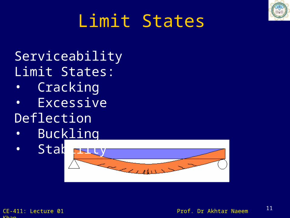
Serviceability Limit States:• Cracking• Excessive Deflection• Buckling• Stability
Limit States
CE-411: Lecture 01 Prof. Dr Akhtar Naeem Khan
12
Limit StatesSpecial Limit States:
Damage or collapse in extreme
earthquakes.
Structural effects of fire, explosions, or
vehicular collisions.
CE-411: Lecture 01 Prof. Dr Akhtar Naeem Khan
Design Approach used must ensure that the probability of a Limit State being reached in the Design/Service Life of a structure is within acceptable limits;
However, complete elimination of probability of a Limit State being achieved in the service life of a structure is impractical as it would result in uneconomical designs.
13
Limit States

CE-411: Lecture 01 Prof. Dr Akhtar Naeem Khan
Design Considerations
• Structure and Structural Members should have adequate strength, stiffness and toughness to ensure proper functioning during service life
• Reserve Strength should be available to cater for:
– Occasional overloads and underestimation of loads
– Variability of strength of materials from those specified
– Variation in strength arising from quality of workmanship and construction practices
14

CE-411: Lecture 01 Prof. Dr. Akhtar Naeem Khan
15
Structural Design must provide adequate margin of safety irrespective of Design Method
Design Approach should take into account the probability of occurrence of failure in the design process
Design Considerations
CE-411: Lecture 01 Prof. Dr. Akhtar Naeem Khan
16
An important goal in design is to prevent limit state from being reached.
It is not economical to design a structure so that none of its members or components could ever fail. Thus, it is necessary to establish an acceptable level of risk or probability of failure.
Design Considerations
CE-411: Lecture 01 Prof. Dr Akhtar Naeem Khan
Brittle behavior is to be avoided as it will imply a sudden loss of load carrying capacity when elastic limit is exceeded.
Reinforced concrete can be made ductile by limiting the steel reinforcement.
17
Design Considerations

CE-411: Lecture 01 Prof. Dr. Akhtar Naeem Khan
18
To determine the acceptable margin of safety, opinion should be sought from experience and qualified group of engineers.
In steel design AISC manuals for ASD & LRFD guidelines can be accepted as reflection of such opinions.
Design Considerations
CE-411: Lecture 01 Prof. Dr. Akhtar Naeem Khan
19
Any design procedure require the confidence of Engineer on the analysis of load effects and strength of the materials.
The two distinct procedures employed by designers are Allowable Stress Design (ASD) & Load & Resistance Factor Design (LRFD).
Design Considerations

CE-411: Lecture 01 Prof. Dr. Akhtar Naeem Khan
20
Safety in the design is obtained by specifying, that the effect of the loads should produce stresses that is a fraction of the yield stress fy, say one half.
Allowable Stress Design (ASD)

CE-411: Lecture 01 Prof. Dr. Akhtar Naeem Khan
21
• This is equivalent to:
FOS = Resistance, R/ Effect of load, Q
= fy/0.5fy
= 2
Allowable Stress Design (ASD)

CE-411: Lecture 01 Prof. Dr Akhtar Naeem Khan
Since the specifications set limit on the stresses, it became allowable stress design (ASD).
It is mostly reasonable where stresses are uniformly distributed over X-section (such on determinate trusses, arches, cables etc.)
22
Allowable Stress Design (ASD)

in Q
R
23
Mathematical Description of A S D
Rn = Resistance or Strength of the component being designed
Φ = Resistance Factor or Strength Reduction Factor
= Overload or Load Factors
= Factor of Safety FS
Qi = Effect of applied loads
CE-411:Lecture No. 1
Allowable Stress Design (ASD)
Prof. Dr. Akhtar Naeem Khan

FS
FFor
FS
FFf cr
by
bb
MFS
M n cI
M
cI
cI
FS
Fy
//
/
24
Mathematical Description of Allowable Stress Design
In ASD we check the adequacy of a design in terms of stresses therefore design checks are cast in terms of stresses for example if:Mn = Nominal Flexural Strength of a BeamM = Moment resulting from applied unfactored loadsFS = Factor of Safety
Allowable Stress Design (ASD)
Prof. Dr. Akhtar Naeem KhanCE-411:Lecture No. 1

CE-411: Lecture 01 Prof. Dr. Akhtar Naeem Khan
25
Section Modulus: S ≥ effect of load/Allowable stress = M/fb ------(ii)
Section Modulus
CE-411: Lecture 01 Prof. Dr. Akhtar Naeem Khan
26
Implied in the ASD method is the assumption that the stress in the member is zero before any loads are applied, i.e., no residual stresses exist from forming the members.
ASD Drawbacks
CE-411: Lecture 01 Prof. Dr. Akhtar Naeem Khan
27
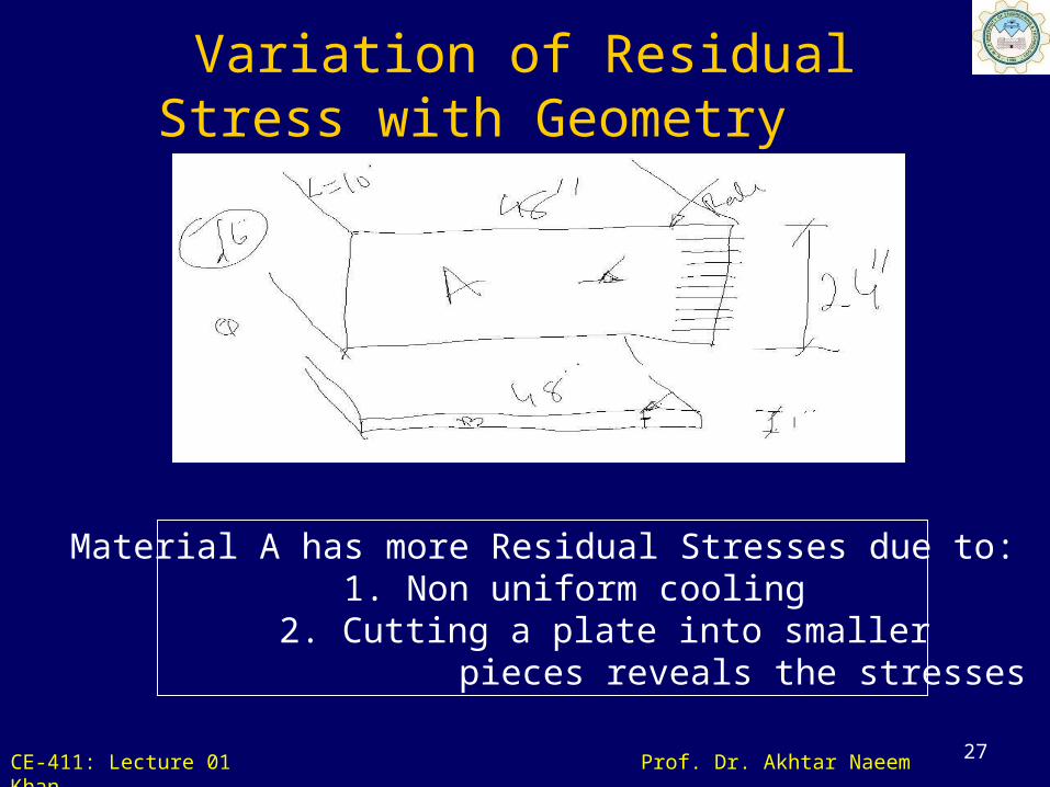
Material A has more Residual Stresses due to: 1. Non uniform cooling
2. Cutting a plate into smaller pieces reveals the stresses
Variation of Residual Stress with Geometry
CE-411: Lecture 01 Prof. Dr. Akhtar Naeem Khan
28
• ASD does not give reasonable measure of strength, which is more fundamental measure of resistance than is allowable stress.
• Another drawback in ASD is that safety is applied only to stress level. Loads are considered to be deterministic (without variation).
ASD Drawbacks
CE-411: Lecture 01 Prof. Dr Akhtar Naeem Khan
To overcome the deficiencies of ASD, the LRFD method is based on:
Strength of Materials
It consider the variability not only in resistance but also in the effects of load.
It provides measure of safety related to probability of failure.
29
Load and Resistance Factor Design (LRFD)

CE-411: Lecture 01 Prof. Dr Akhtar Naeem Khan
30
Safety in the design is obtained by specifying that the reduced Nominal Strength of a designed structure is less than the effect of factored loads acting on the structure
in QnR
Rn = Resistance or Strength of the component being designedQi = Effect of Applied Loadsn = Takes into account ductility, redundancy and operational imp. Φ = Resistance Factor or Strength Reduction Factor = Overload or Load Factors
= Factor of Safety
Load and Resistance Factor Design (LRFD)

CE-411: Lecture 01 Prof. Dr. Akhtar Naeem Khan
31
Ductility: It implies a large capacity for inelastic deformation without rupture
Ductility will ensure
redistribution of load through
inelastic deformation.
The role of ‘n’
CE-411: Lecture 01 Prof. Dr. Akhtar Naeem Khan
32
Redundancy:
1. A simply supported beam is a determinate structure so it has no redundant actions.
2. A fixed beam is indeterminate by 2 degrees so it has two redundant actions.
The role of ‘n’

CE-411: Lecture 01 Prof. Dr. Akhtar Naeem Khan
33
Yielding will initiate at mid span due to maximum moment at mid span with no Redistribution of load
Redundancy

CE-411: Lecture 01 Prof. Dr. Akhtar Naeem Khan
34
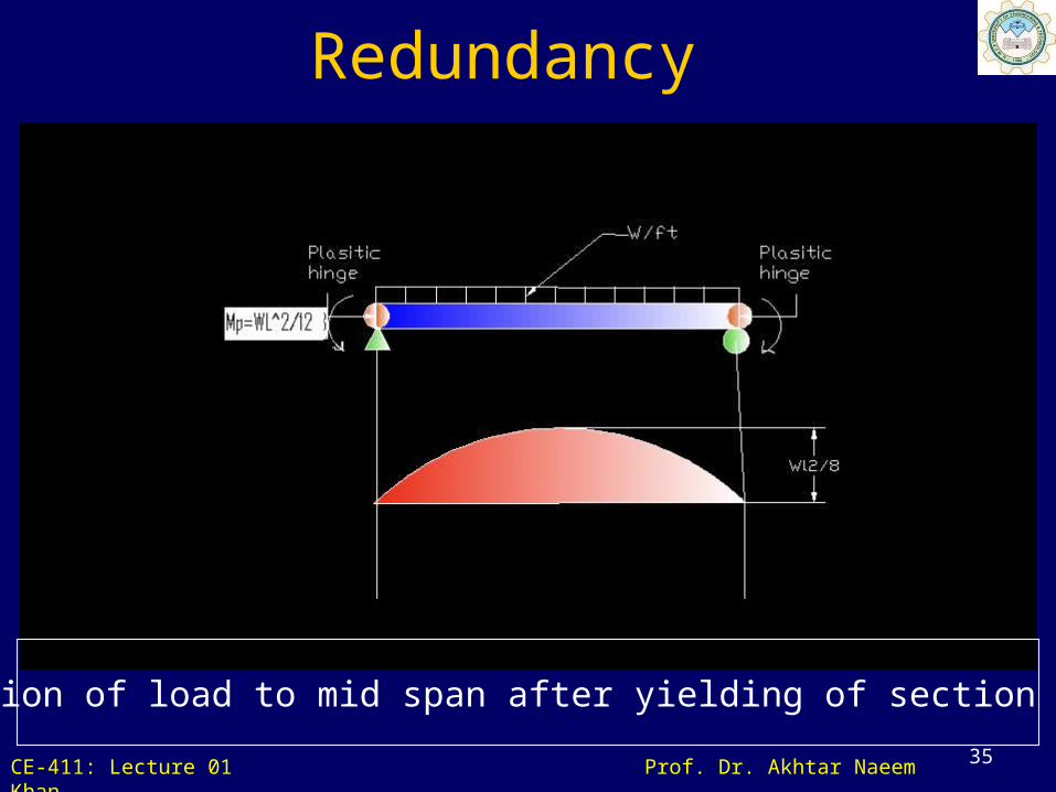
Yielding will initiate at supports due to maximum moment at supports
Redundancy
CE-411: Lecture 01 Prof. Dr. Akhtar Naeem Khan
35
Redistribution of load to mid span after yielding of section at supports
Redundancy
CE-411: Lecture 01 Prof. Dr. Akhtar Naeem Khan
36
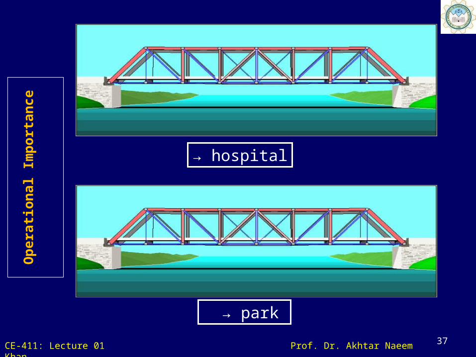
Operational Importance:
A hospital and a school require more conservative design than an ordinary residential building.
The role of ‘n’
CE-411: Lecture 01 Prof. Dr. Akhtar Naeem Khan
37
→ hospital
→ park
Op
era
tion
al Im
port
an
ce

CE-411: Lecture 01 Prof. Dr Akhtar Naeem Khan
LRFD accounts for both variability in resistance and load.
It achieves fairly uniform levels of safety for different limit states.
38
LRFD Advantages

CE-411: Lecture 01 Prof. Dr Akhtar Naeem Khan
It’s disadvantage is change in design philosophy from previous method.
39
LRFD Disadvantages
CE-411: Lecture 01 Prof. Dr. Akhtar Naeem Khan
40
ASD combines Dead and Live Loads and treats them in the same way
In LRFD different load factors are assigned to Dead Loads and Live Loads which is appealing
Changes in load factors and resistance factors are much easier to make in LRFD compared to changing the allowable stress in ASD
Comparison of ASD and LRFD Design Approaches
CE-411: Lecture 01 Prof. Dr. Akhtar Naeem Khan
41
LRFD is intrinsically appealing as it requires better understanding of behavior of the structure in its limit states
Design approach similar to LRFD is being followed in Design of concrete structures in form of Ultimate Strength Design -- why not use similar approach design of steel structures?
Comparison of ASD and LRFD Design Approaches

CE-411: Lecture 01 Prof. Dr Akhtar Naeem Khan
ASD indirectly incorporates the Factors of Safety by limiting the stress whereas LRFD aims to specify Factors of Safety directly by specifying Resistance Factors and Load Factors
LRFD is more rational as different Factors of Safety can be assigned to different loadings such as Dead Loads, Live Loads, Earthquake Loads and Impact Loads
42
Comparison of ASD and LRFD Design Approaches

CE-411: Lecture 01 Prof. Dr. Akhtar Naeem Khan
43
LRFD considers variability not only in resistance but also in the effects of load which provides measure of safety related to probability of failure
It achieves fairly uniform levels of safety for different limit states.
ASD still remains as a valid Design Method
Comparison of ASD and LRFD Design Approaches
CE-411: Lecture 01 Prof. Dr. Akhtar Naeem Khan
)/(1
)/(07.18.0
67.167.1
78.133.1
DL
DL
LD
LD
ASD
LRFD
)/(1
93.0
67.167.1
56.1
DLLD
D
ASD
LRFD
44
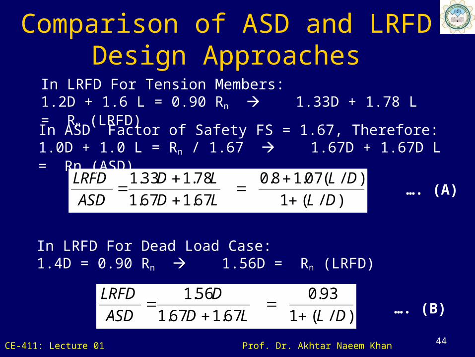
In LRFD For Tension Members:1.2D + 1.6 L = 0.90 Rn 1.33D + 1.78 L = Rn (LRFD)
In ASD Factor of Safety FS = 1.67, Therefore:1.0D + 1.0 L = Rn / 1.67 1.67D + 1.67D L = Rn (ASD)
In LRFD For Dead Load Case:1.4D = 0.90 Rn 1.56D = Rn (LRFD)
…. (A)
…. (B)
Comparison of ASD and LRFD Design Approaches

CE-411: Lecture 01 Prof. Dr. Akhtar Naeem Khan
45
0.7
0.8
0.9
1.0
1 2 3 4 5 6
0.93
0.12
0.83
1.4D
1.2D + 1.6L
LR
FD
AS
D
Live Load Dead Load
3%
Comparison of ASD and LRFD Design Approaches

CE-411: Lecture 01 Prof. Dr Akhtar Naeem Khan
AREA Stands for American Railway Engineers Association (AREA)
Railway Bridges and Structures are usually designed using provisions of the AREA Code
AREA Code uses only the Allowable Stress Design Method. However, the allowable stresses and design requirements may differ from AISC/ASD method
46
AREA Code for Design of Railway Structures

CE-411: Lecture 01 Prof. Dr Akhtar Naeem Khan
• AASHTO Stands for Association of American State and Highway Transportation Officials (AASHTO)
• Highway Bridges are usually designed using provisions of the AASHTO Code
• AASHTO Code uses both ASD and LRFD Design Methods
47
AASHTO Code for Design of Highway Bridges

CE-411: Lecture 01 Prof. Dr Akhtar Naeem Khan
It is very difficult to devise a design code that is applicable to all uses and all types of structures such as buildings, highway bridges, railway bridges and transmission towers
The responsibility of infrastructure on roads, bridges and electrical transmission towers rests with the organization responsible for approving, operating and maintaining these facilities
48
The role of various Codes
CE-411: Lecture 01 Prof. Dr. Akhtar Naeem Khan
49
Uses and critical loads may be different in different types of structures and no one code can cater to all the different important considerations
For above reasons different codes prevail and will continue to do so
AISC ASD Code and LRFD Code primarily is pertinent to Building Structures.
The role of various Codes

CE-411: Lecture 01 Prof. Dr Akhtar Naeem Khan
Overview of LRFD ManualPart 1: Dimensions and properties
Part 2: General Design considerations
Part 3: Design of flexural members
Part 4: Design of compression members
Part 5: Design of Tension members
Part 6: Design of members subject to combined loading
50
CE-411: Lecture 01 Prof. Dr Akhtar Naeem Khan
Overview of LRFD ManualPart 7: Design considerations for bolts
Part 8: Design considerations for welds
Part 9: Design of connecting elements
Part 10: Design of simple shear connections
Part 11: Design of flexible moment connections
51
CE-411: Lecture 01 Prof. Dr Akhtar Naeem Khan
Overview of LRFD ManualPart 12: Design of fully restrained (FR)
moment connections
Part 13: Design of Bracing connections and truss connections
Part 14: Design of Beam bearing plates, Column base plates, anchor
rods, and column splices.
52
CE-411: Lecture 01 Prof. Dr Akhtar Naeem Khan
Overview of LRFD ManualPart 15: Design of Hanger connections,
Bracket plates, and Crane-rail connections
ANSI/LRFD Specifications for structural steel Buildings.
53
CE-411: Lecture 01 Prof. Dr Akhtar Naeem Khan
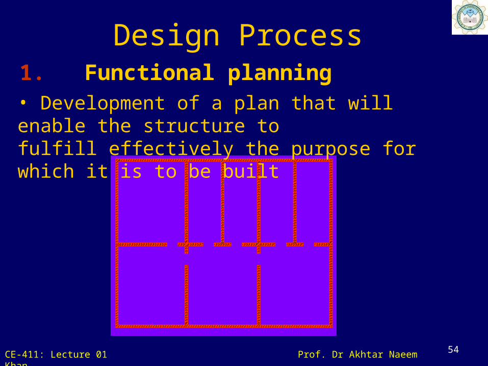
54
1. Functional planning• Development of a plan that will enable the structure to fulfill effectively the purpose for which it is to be built
Design Process
CE-411: Lecture 01 Prof. Dr. Akhtar Naeem Khan
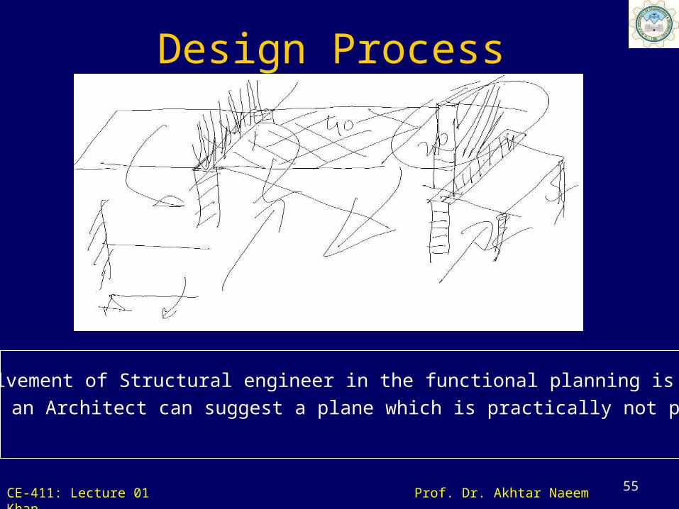
55
The involvement of Structural engineer in the functional planning is very imp
because an Architect can suggest a plane which is practically not possible.
Design Process
CE-411: Lecture 01 Prof. Dr Akhtar Naeem Khan
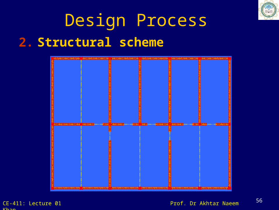
56
2. Structural scheme
Design Process
CE-411: Lecture 01 Prof. Dr Akhtar Naeem Khan
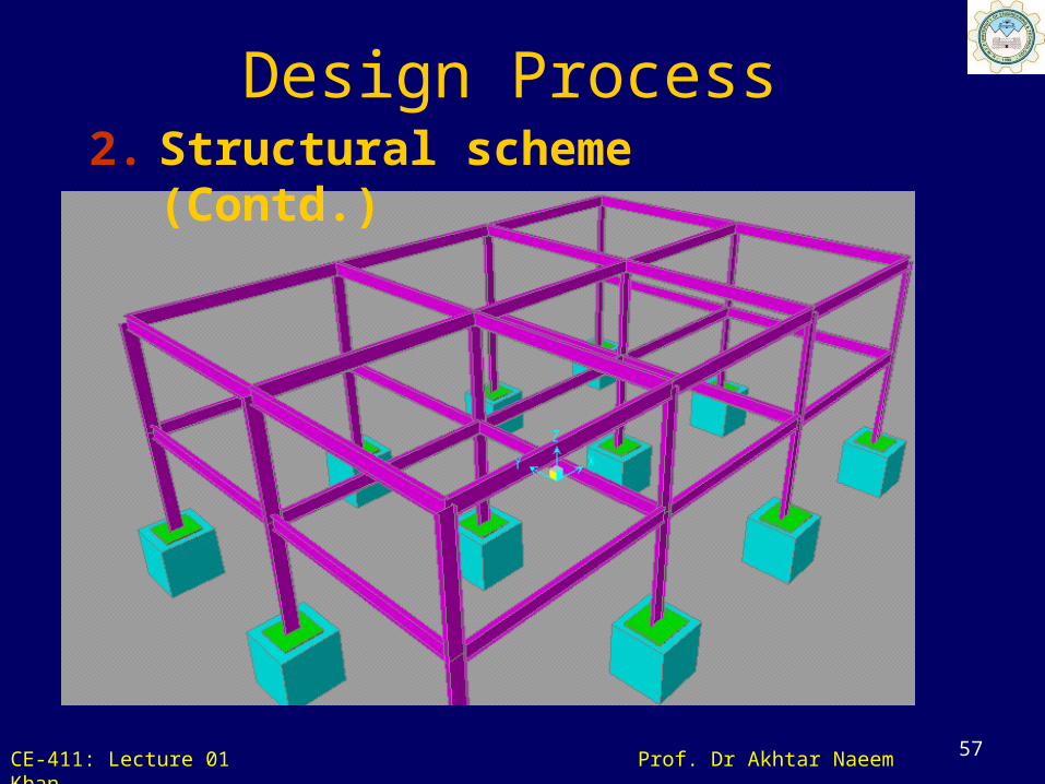
57
2. Structural scheme (Contd.)
Design Process
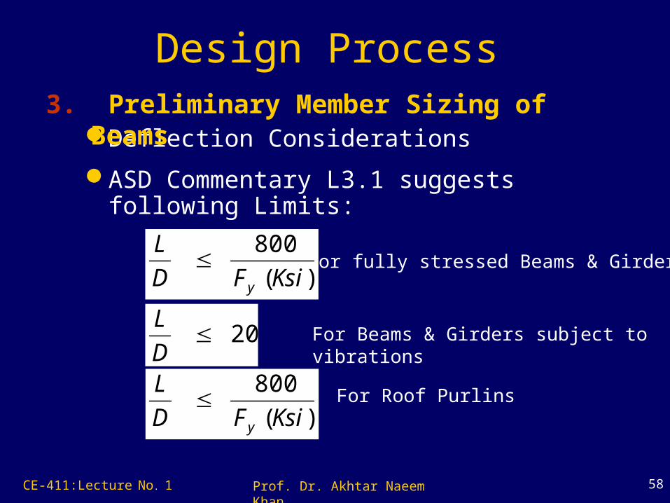
58
Deflection Considerations
ASD Commentary L3.1 suggests following Limits:
3. Preliminary Member Sizing of Beams
For fully stressed Beams & Girders)(
800
KsiFD
L
y
20D
L
)(
800
KsiFD
L
y
For Beams & Girders subject to vibrations
For Roof Purlins
Design Process
CE-411:Lecture No. 1 Prof. Dr. Akhtar Naeem Khan

59
Strength/Capacity Considerations
3. Preliminary Member Sizing of Beams
Tributary Area
BeamUnbraced Length
Des
ign
Mom
ent
Design Process
CE-411:Lecture No. 1 Prof. Dr. Akhtar Naeem Khan

60
Strength/Capacity Considerations
3. Preliminary Member Sizing of Columns
Tributary Area
• Use of Tributary Areas and Column Tables
Design Process
CE-411:Lecture No. 1 Prof. Dr. Akhtar Naeem Khan

CE-411: Lecture 01 Prof. Dr. Akhtar Naeem Khan
61
Tributary Area

CE-411: Lecture 01 Prof. Dr Akhtar Naeem Khan
62
Design Process 4. Structural Analysis - Modeling
CE-411: Lecture 01 Prof. Dr Akhtar Naeem Khan
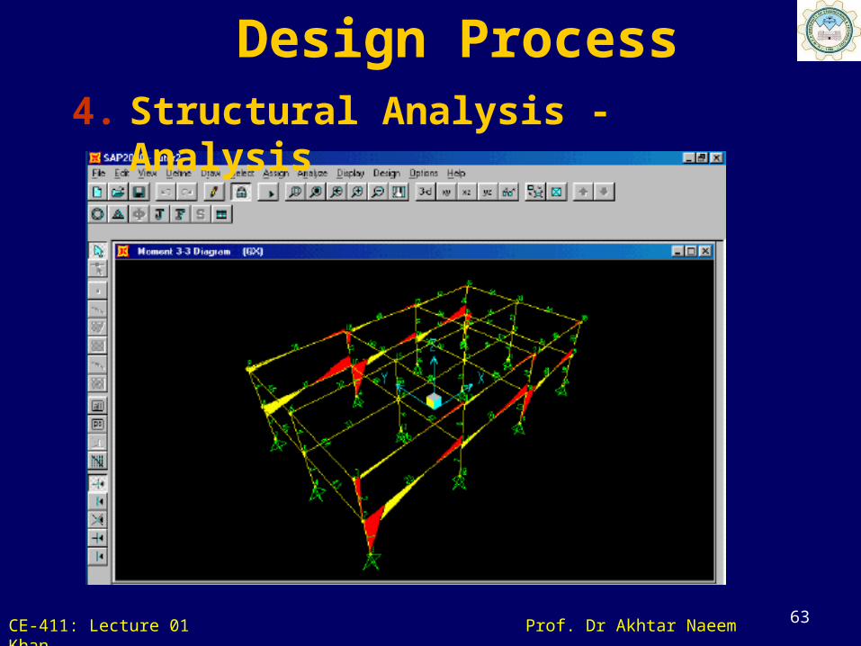
63
Design Process 4. Structural Analysis - Analysis

CE-411: Lecture 01 Prof. Dr Akhtar Naeem Khan
64
Design Process
• Must be chosen so that they will be able to resist, within appropriate margin of safety, the forces which the structural analysis has disclosed.
5. Design Review/ Member Modification

CE-411: Lecture 01 Prof. Dr Akhtar Naeem Khan
65
Design Process
• Make a tentative cost estimates for several preliminary structural layouts.
• Selection of constructional material based on: • Availability of specific material• Corresponding skilled labor• Relative costs• Wage scales
6. Cost Estimation

CE-411: Lecture 01 Prof. Dr Akhtar Naeem Khan
66
Design Process
7. Preparation of Structural Drawings & Specifications
CE-411: Lecture 01 Prof. Dr. Akhtar Naeem Khan
67
Thanks