LD C B S 1 X 4...110=110VAC, 220=220VAC (2 prong Euro), 240=240VAC (3 prong UK), MC – Military DC...
5
L DCBS1X4 Passive 1X4 GPS Splitter Technical Product Data Features • Amplitude Balance |J1 – J4| < 1.0dB, • Extremely Flat Group Delay Less that 1ns variation • Low Insertion Loss • Passes all GNSS Frequencies (Entire L-band) • DC Blocked Outputs Feature 200Ω Loads Prevent antenna alarm faults from connected devices • Phase Matched Outputs Phase (J1 – J4) < 1.0 o • Special Configurations Available By Request Description The LDCBS1X4 GPS Splitter (GNSS Splitter) is a one input, four output device based on the Wilkinson splitter design. The frequency response covers the entire L-band (all GNSS Frequencies) with excellent gain flatness. In the standard configuration, (J1) passes DC from the connected GPS device through the splitter to the input (antenna port). The other RF outputs (J2-J4) are DC blocked and loaded with a 200Ω resistor to simulate the antenna current draw to prevent false antenna alarm faults. Contact GPS Networking Technical Support for any questions regarding standard configurations or special configurations at [email protected] or 1-800-463-3063. 05/30/18 1
Transcript of LD C B S 1 X 4...110=110VAC, 220=220VAC (2 prong Euro), 240=240VAC (3 prong UK), MC – Military DC...
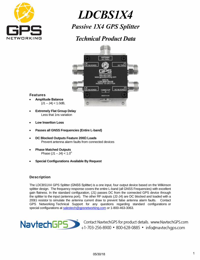
L D C B S 1 X 4Passive 1X4 GPS Splitter
Technical Product Data
Features • Amplitude Balance
|J1 – J4| < 1.0dB,
• Extremely Flat Group DelayLess that 1ns variation
• Low Insertion Loss
• Passes all GNSS Frequencies (Entire L-band)
• DC Blocked Outputs Feature 200Ω LoadsPrevent antenna alarm faults from connected devices
• Phase Matched OutputsPhase (J1 – J4) < 1.0o
• Special Configurations Available By Request
Description
The LDCBS1X4 GPS Splitter (GNSS Splitter) is a one input, four output device based on the Wilkinson splitter design. The frequency response covers the entire L-band (all GNSS Frequencies) with excellent gain flatness. In the standard configuration, (J1) passes DC from the connected GPS device through the splitter to the input (antenna port). The other RF outputs (J2-J4) are DC blocked and loaded with a 200Ω resistor to simulate the antenna current draw to prevent false antenna alarm faults. Contact GPS Networking Technical Support for any questions regarding standard configurations or special configurations at [email protected] or 1-800-463-3063.
05/30/18 1
pdanko
NGPS Horizontal
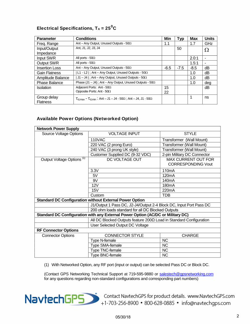
Electrical Specifications, TA = 250C
Parameter Conditions Min Typ Max Units Freq. Range Ant – Any Output, Unused Outputs - 50Ω 1.1 1.7 GHz Input/Output Impedance
Ant, J1, J2, J3, J4 50 Ω Input SWR All ports - 50Ω 2.0:1 - Output SWR All ports - 50Ω 1.5:1 - Insertion Loss Ant – Any Output, Unused Outputs - 50Ω -6.5 -7.5 -8.5 dB Gain Flatness | L1 - L2 | ; Ant – Any Output, Unused Outputs - 50Ω 1.0 dB Amplitude Balance | J1 – J4 | ; Ant – Any Output, Unused Outputs - 50Ω 1.0 dB Phase Balance Phase (J1 – J4) ; Ant – Any Output, Unused Outputs - 50Ω 1.0 deg Isolation Adjacent Ports: Ant - 50Ω
Opposite Ports: Ant - 50Ω 15 22
dB
Group delay Flatness
τd,max - τd,min : Ant – J1 – J4 - 50Ω ; Ant – J4, J1 - 50Ω 1 ns
Available Power Options (Networked Option)
Network Power Supply Source Voltage Options VOLTAGE INPUT STYLE
110VAC Transformer (Wall Mount) 220 VAC (2 prong Euro) Transformer (Wall Mount) 240 VAC (3 prong UK style) Transformer (Wall Mount) Customer Supplied DC (9-32 VDC) 2-pin Military DC Connector
Output Voltage Options (1) DC VOLTAGE OUT MAX CURRENT OUT FOR CORRESPONDING Vout
3.3V 110mA 5V 120mA 9V 140mA 12V 180mA 15V 220mA Custom TDB
Standard DC Configuration without External Power Option J1/Output 1 Pass DC, J2-J4/Output 2-4 Block DC, Input Port Pass DC 200 ohm loads standard for all DC Blocked Outputs
Standard DC Configuration with any External Power Option (AC/DC or Military DC) All DC Blocked Outputs feature 200Ω Load in Standard Configuration User Selected Output DC Voltage
RF Connector Options Connector Options CONNECTOR STYLE CHARGE
Type N-female NC Type SMA-female NC Type TNC-female NC Type BNC-female NC
(1) With Networked Option, any RF port (input or output) can be selected Pass DC or Block DC.
(Contact GPS Networking Technical Support at 719-595-9880 or [email protected] for any questions regarding non-standard configurations and corresponding part numbers)
05/30/18 2
pdanko
NGPS Horizontal
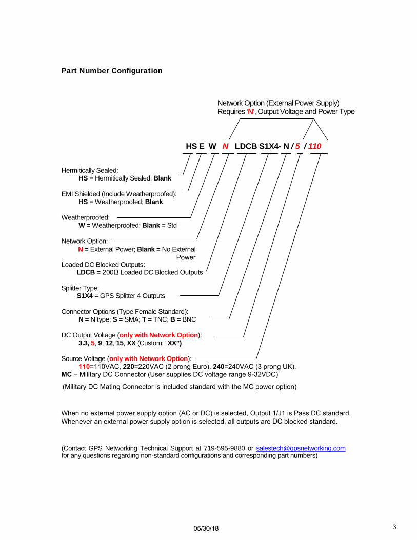
Part Number Configuration
Network Option (External Power Supply) Requires ‘N’, Output Voltage and Power Type
HS E W N LDCB S1X4- N / 5 / 110
Hermitically Sealed: HS = Hermitically Sealed; Blank
EMI Shielded (Include Weatherproofed): HS = Weatherproofed; Blank
Weatherproofed: W = Weatherproofed; Blank = Std
Network Option: N = External Power; Blank = No External
PowerLoaded DC Blocked Outputs:
LDCB = 200Ω Loaded DC Blocked Outputs
Splitter Type: S1X4 = GPS Splitter 4 Outputs
Connector Options (Type Female Standard): N = N type; S = SMA; T = TNC; B = BNC
DC Output Voltage (only with Network Option): 3.3, 5, 9, 12, 15, XX (Custom: “XX”)
Source Voltage (only with Network Option): 110=110VAC, 220=220VAC (2 prong Euro), 240=240VAC (3 prong UK), MC – Military DC Connector (User supplies DC voltage range 9-32VDC)
(Military DC Mating Connector is included standard with the MC power option)
When no external power supply option (AC or DC) is selected, Output 1/J1 is Pass DC standard. Whenever an external power supply option is selected, all outputs are DC blocked standard.
(Contact GPS Networking Technical Support at 719-595-9880 or [email protected] for any questions regarding non-standard configurations and corresponding part numbers)
05/30/18 3
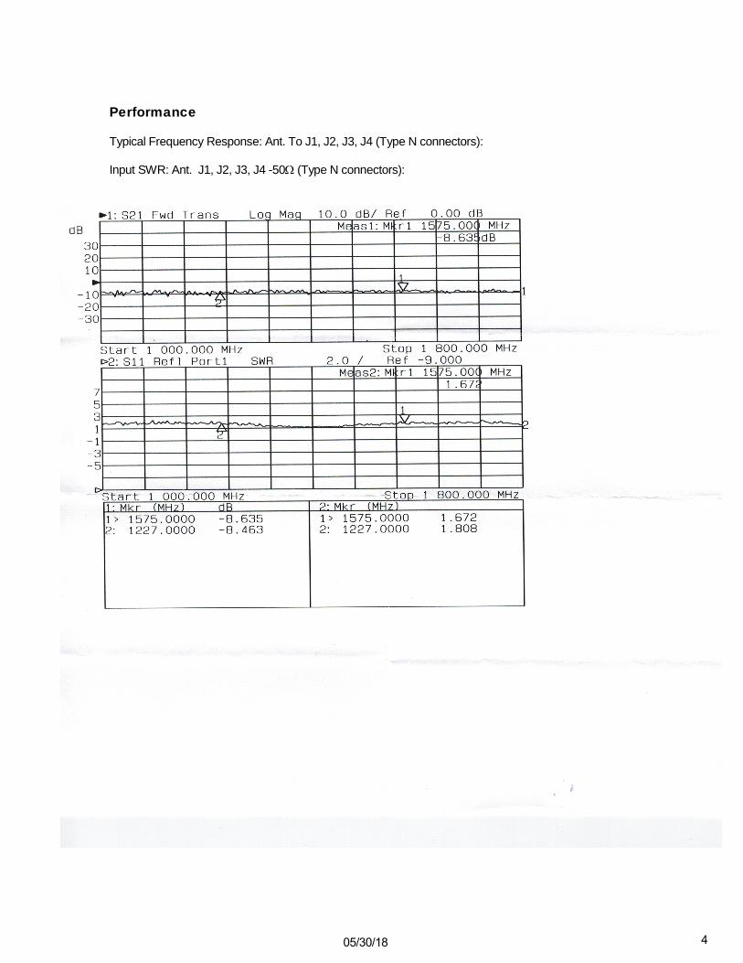
Performance
Typical Frequency Response: Ant. To J1, J2, J3, J4 (Type N connectors):
Input SWR: Ant. J1, J2, J3, J4 -50Ω (Type N connectors):
05/30/18 4
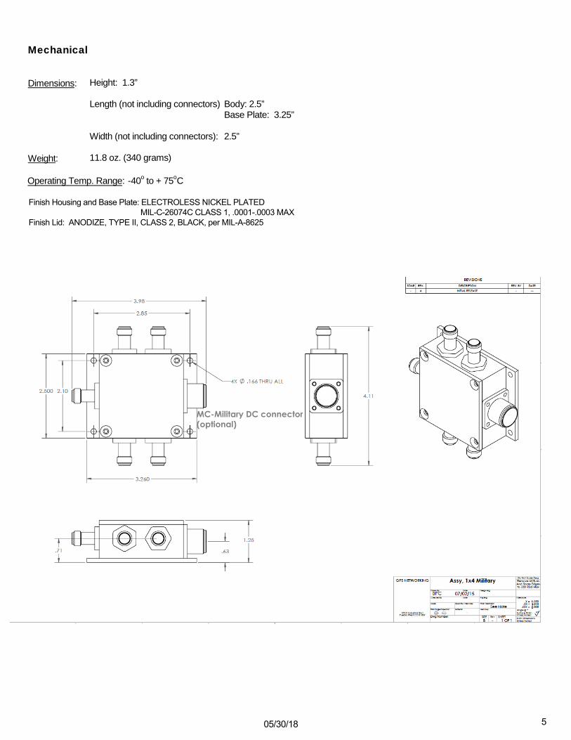
Mechanical
Dimensions: Height: 1.3”
Length (not including connectors) Body: 2.5” Base Plate: 3.25”
Width (not including connectors): 2.5”
Weight: 11.8 oz. (340 grams)
Operating Temp. Range: -40o to + 75oC
Finish Housing and Base Plate: ELECTROLESS NICKEL PLATED MIL-C-26074C CLASS 1, .0001-.0003 MAX
Finish Lid: ANODIZE, TYPE II, CLASS 2, BLACK, per MIL-A-8625
MC-Military DC connector(optional)
05/30/18 5