Kaon Monitoring in MiniBooNE: The LMC Detector · Monte Carlo (GEANT4, MARS, GFLUKA) Production...
39
Kaon Monitoring in MiniBooNE: The LMC Detector E. D. Zimmerman University of Colorado NBI 2003 KEK, Tsukuba November 10, 2003
Transcript of Kaon Monitoring in MiniBooNE: The LMC Detector · Monte Carlo (GEANT4, MARS, GFLUKA) Production...
Kaon Monitoring in MiniBooNE:The LMC Detector
E. D. ZimmermanUniversity of Colorado
NBI 2003KEK, Tsukuba
November 10, 2003
Kaon Monitoring at MiniBooNE1) K-decay νe background at BooNE
� K production estimates
2) Decay kinematics
3) The “Little Muon Counter” (LMC)
� Concept/Placement
� Civil construction/infrastructure
� Collimator
� Fiber Tracker
� Temporary detector
� Status
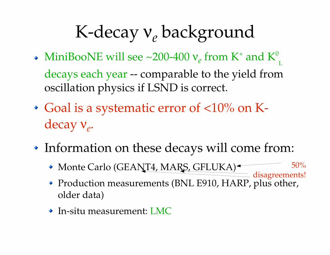
K-decay νe backgroundMiniBooNE will see ~200-400 νe from K+ and K0
L
decays each year -- comparable to the yield from oscillation physics if LSND is correct.
Goal is a systematic error of <10% on K-decay νe.
Information on these decays will come from:Monte Carlo (GEANT4, MARS, GFLUKA)
Production measurements (BNL E910, HARP, plus other, older data)
In-situ measurement: LMC
50%disagreements!
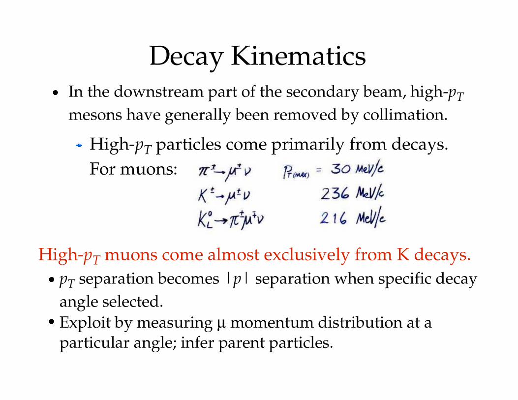
Decay Kinematics
� In the downstream part of the secondary beam, high-pT mesons have generally been removed by collimation.
High-pT particles come primarily from decays. For muons:
High-pT muons come almost exclusively from K decays.
� pT separation becomes |p| separation when specific decay angle selected.
� Exploit by measuring µ momentum distribution at a particular angle; infer parent particles.
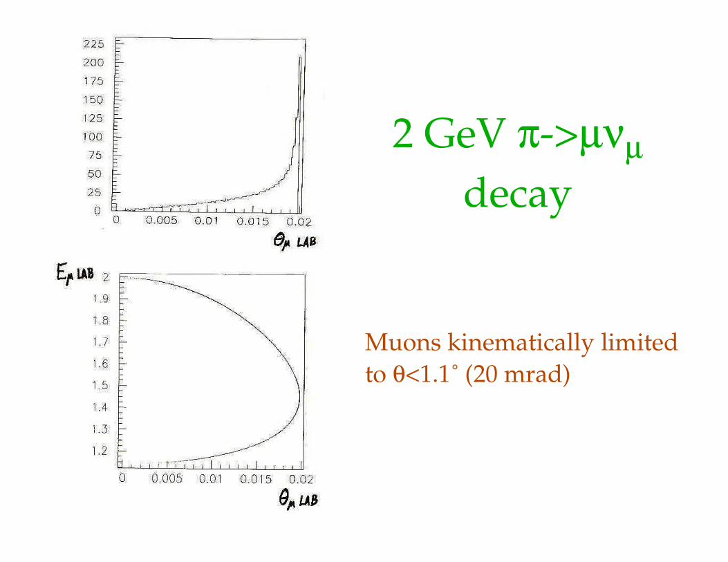
2 GeV π->µνµdecay
Muons kinematically limited to θ<1.1 (20 mrad)˚
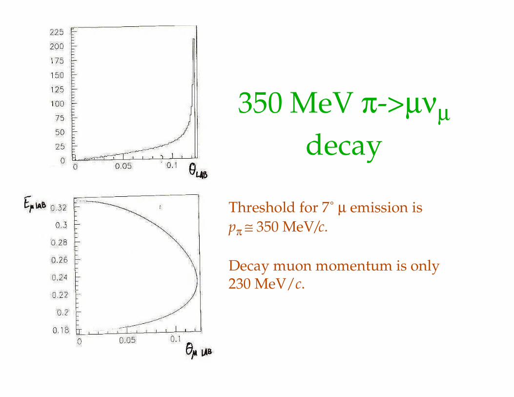
350 MeV π->µνµdecay
Threshold for 7 ˚ µ emission is pπ ≅ 350 MeV/c.
Decay muon momentum is only 230 MeV/c.
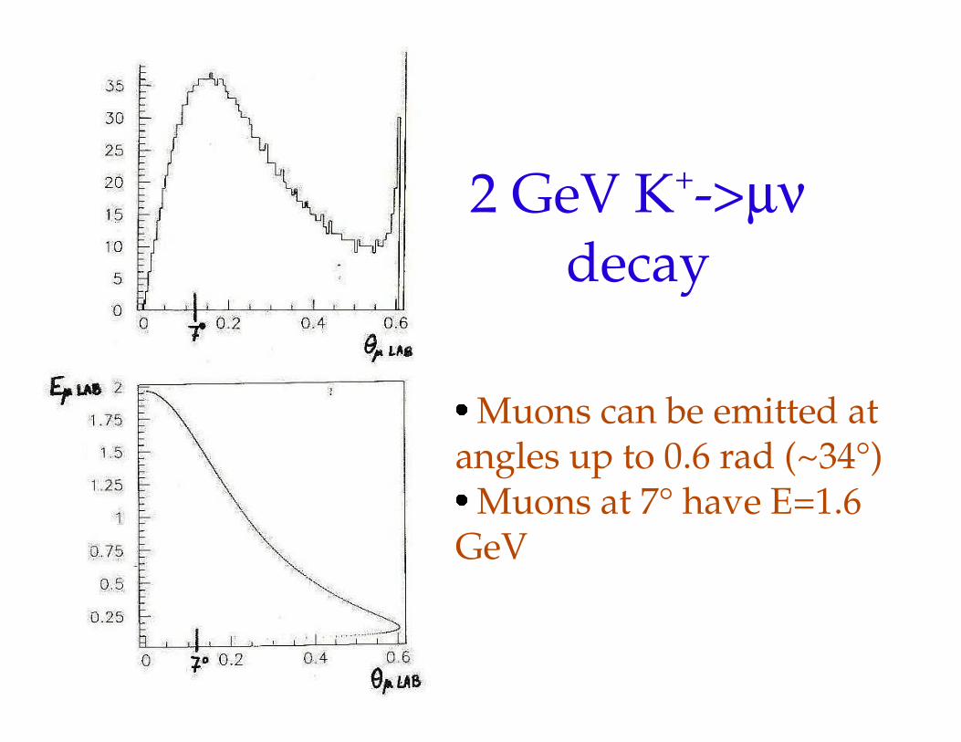
2 GeV K+->µνdecay
� Muons can be emitted at angles up to 0.6 rad (~34°)
� Muons at 7° have E=1.6 GeV
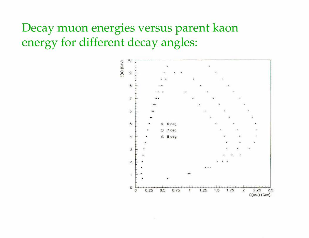
Decay muon energies versus parent kaon energy for different decay angles:
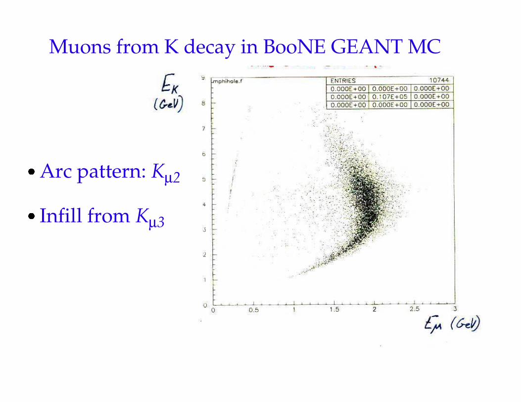
Muons from K decay in BooNE GEANT MC
� Arc pattern: Kµ2
� Infill from Kµ3
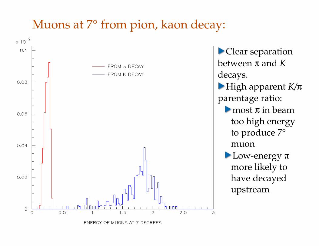
Muons at 7° from pion, kaon decay:
Clear separation between π and K decays.
High apparent K/π parentage ratio:
most π in beam too high energy to produce 7° muonLow-energy π more likely to have decayed upstream
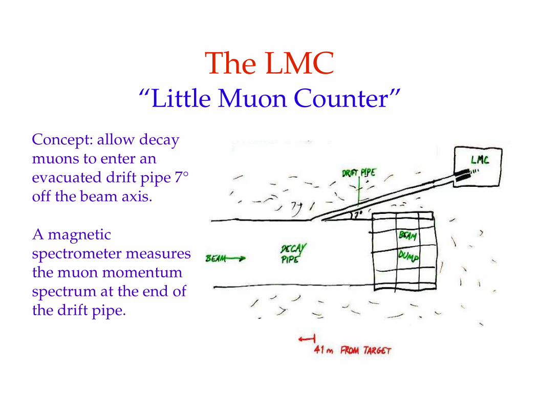
The LMC“Little Muon Counter”
Concept: allow decay muons to enter an evacuated drift pipe 7° off the beam axis.
A magnetic spectrometer measures the muon momentum spectrum at the end of the drift pipe.
LMC GroupA subset of the BooNE collaboration
University of Colorado:T. L. Hart, H. A. Koepke, R. H. Nelson, E. D. Zimmerman
Columbia University:J. Formaggio (now at Univ. of Washington)
Princeton University:A. O. Bazarko, J. Hunt, P. D. Meyers
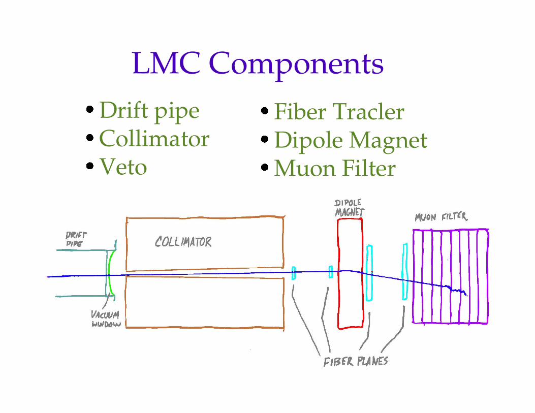
LMC Components
� Drift pipe
� Collimator
� Veto
� Fiber Tracler
� Dipole Magnet
� Muon Filter
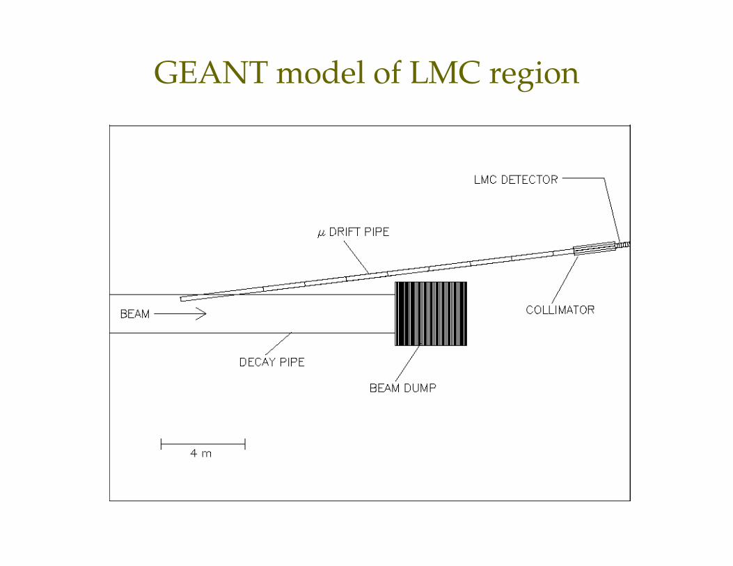
GEANT model of LMC region
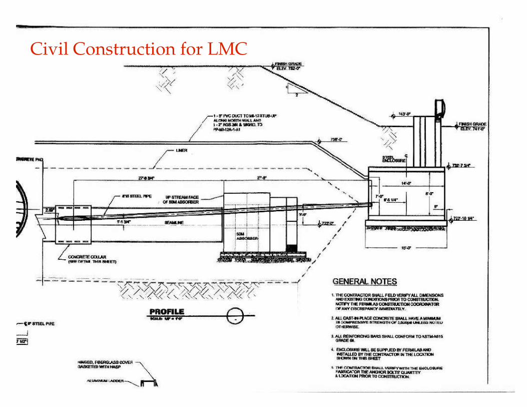
Civil Construction for LMC
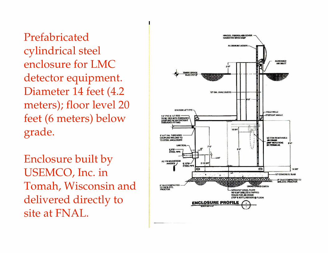
Prefabricated cylindrical steel enclosure for LMC detector equipment. Diameter 14 feet (4.2 meters); floor level 20 feet (6 meters) below grade.
Enclosure built by USEMCO, Inc. in Tomah, Wisconsin and delivered directly to site at FNAL.
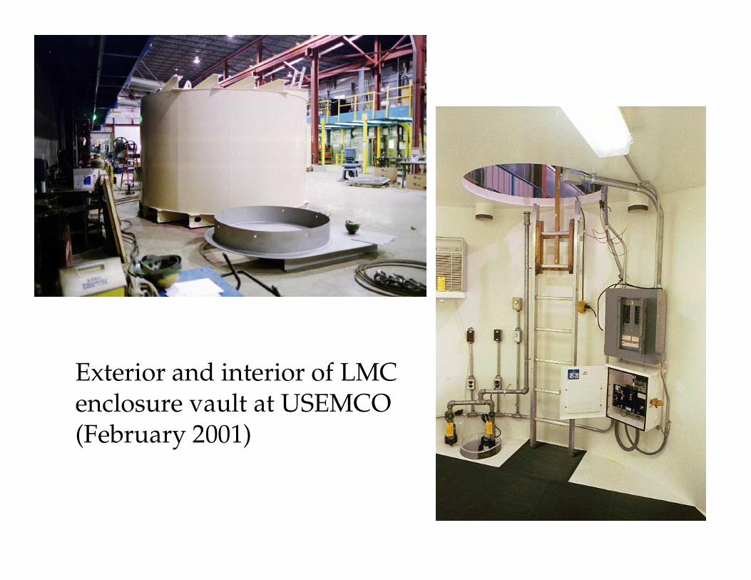
Exterior and interior of LMCenclosure vault at USEMCO(February 2001)
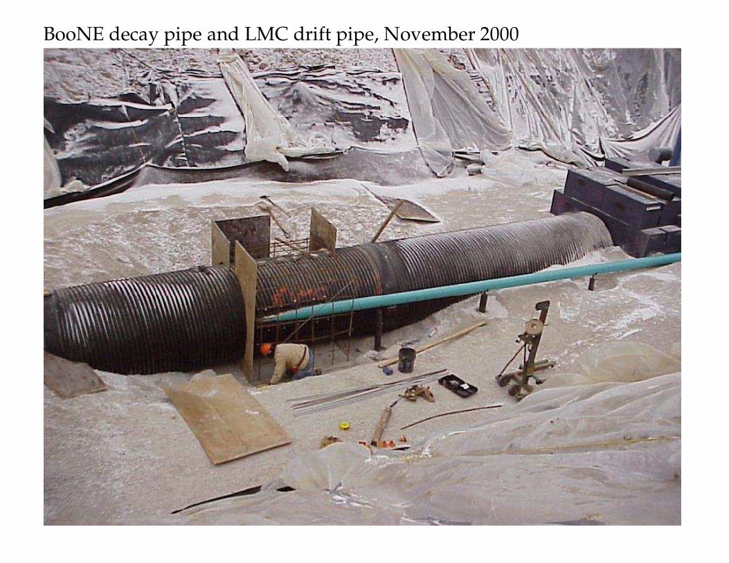
BooNE decay pipe and LMC drift pipe, November 2000
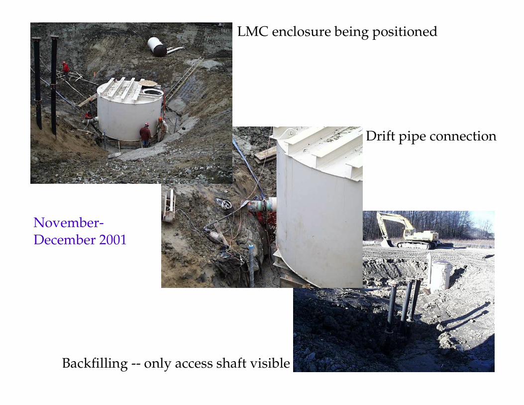
LMC enclosure being positioned
Drift pipe connection
Backfilling -- only access shaft visible
November-December 2001
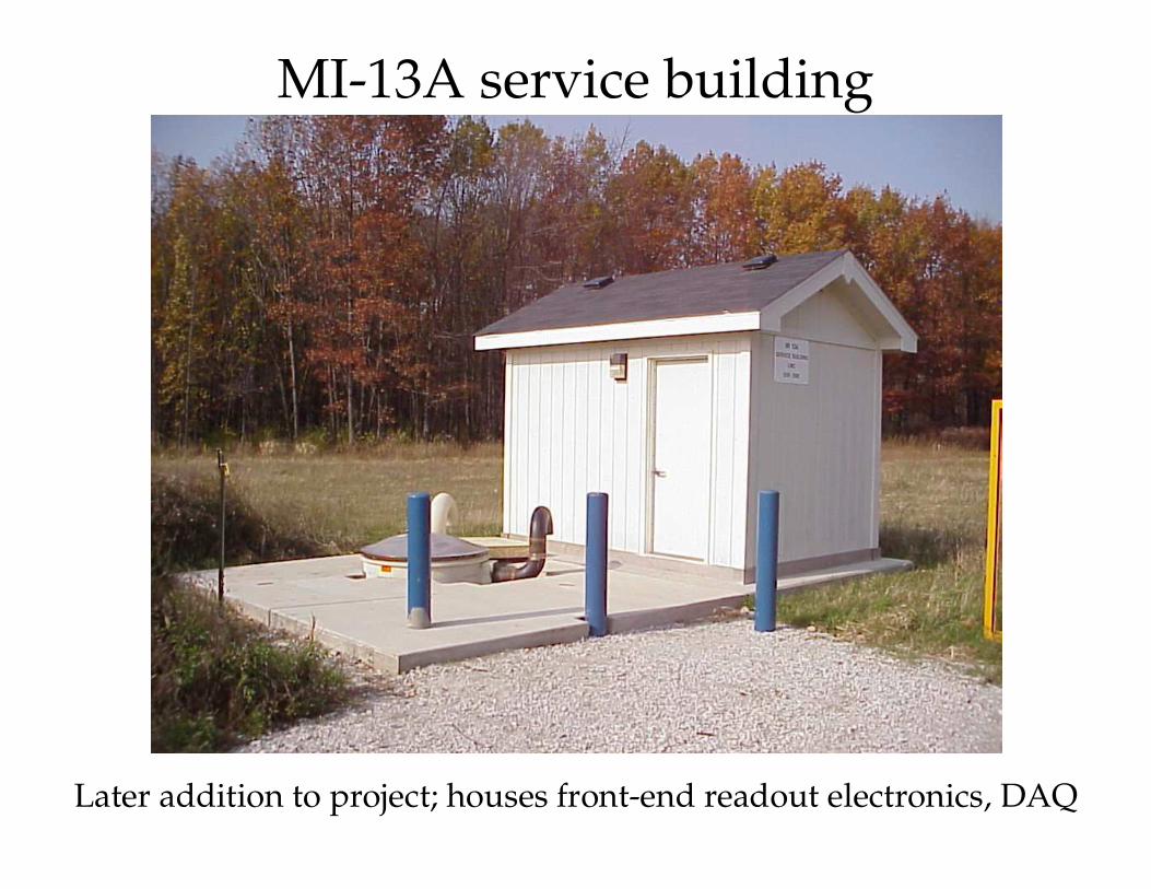
MI-13A service building
Later addition to project; houses front-end readout electronics, DAQ
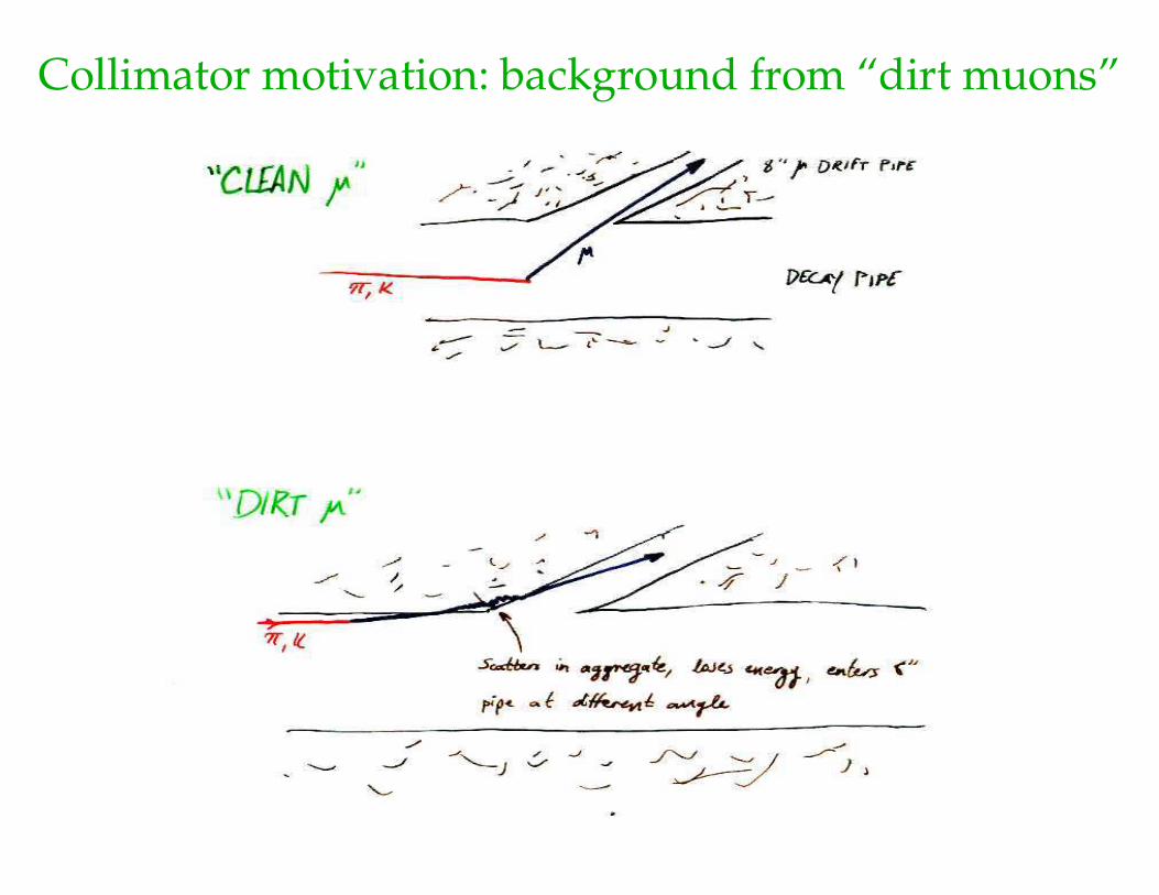
Collimator motivation: background from “dirt muons”
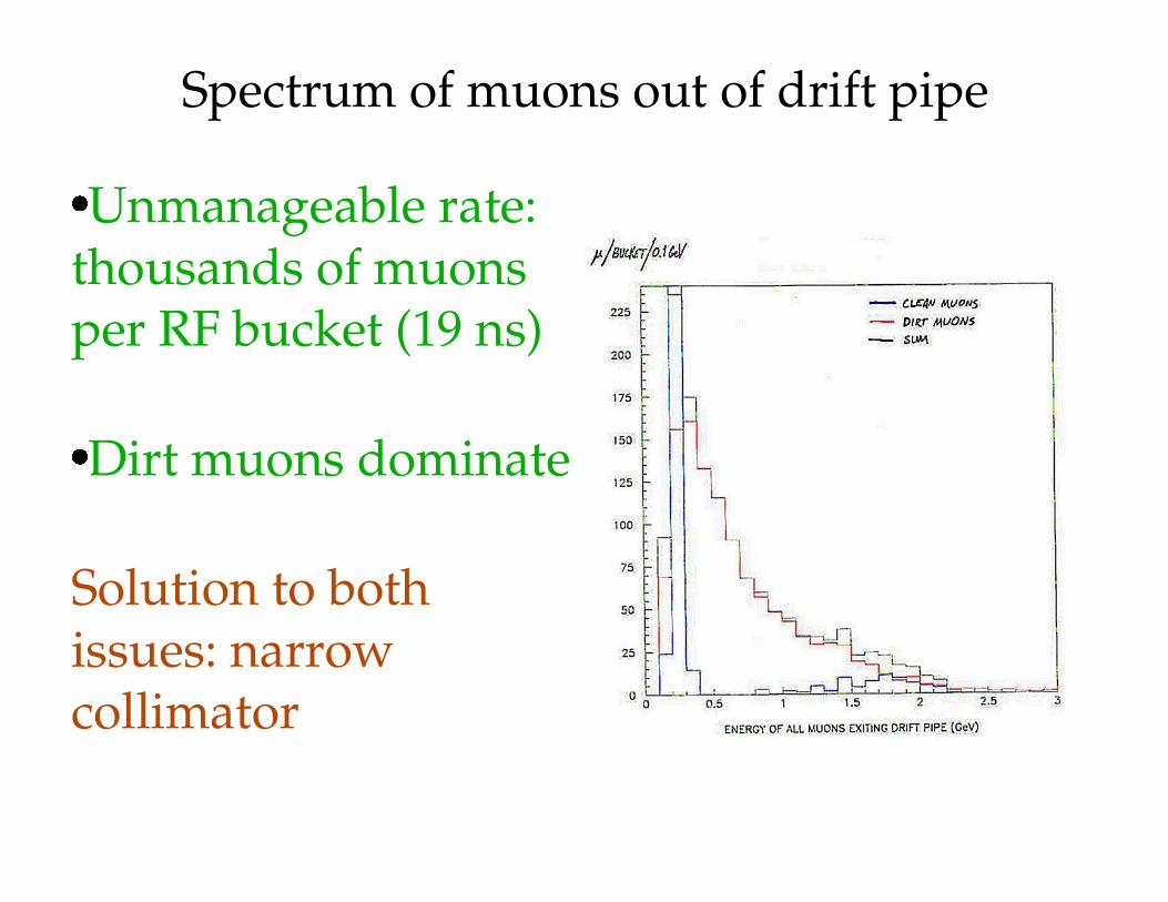
Spectrum of muons out of drift pipe
�Unmanageable rate: thousands of muons per RF bucket (19 ns)
�Dirt muons dominate
Solution to both issues: narrow collimator
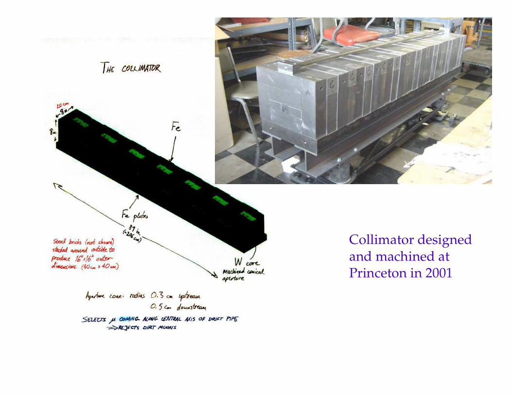
Collimator designedand machined atPrinceton in 2001
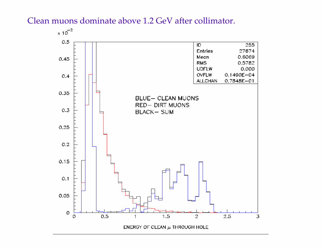
Clean muons dominate above 1.2 GeV after collimator.
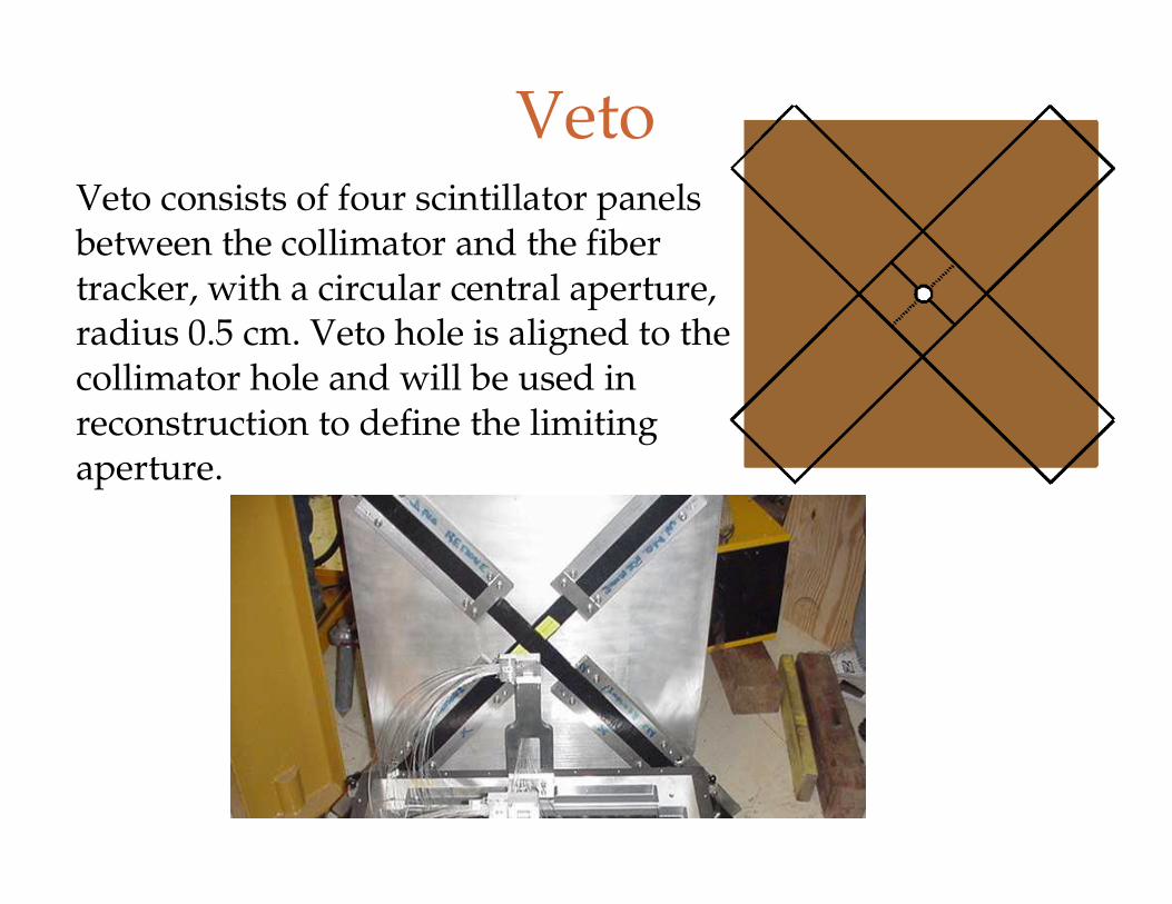
VetoVeto consists of four scintillator panels between the collimator and the fiber tracker, with a circular central aperture, radius 0.5 cm. Veto hole is aligned to the collimator hole and will be used in reconstruction to define the limiting aperture.
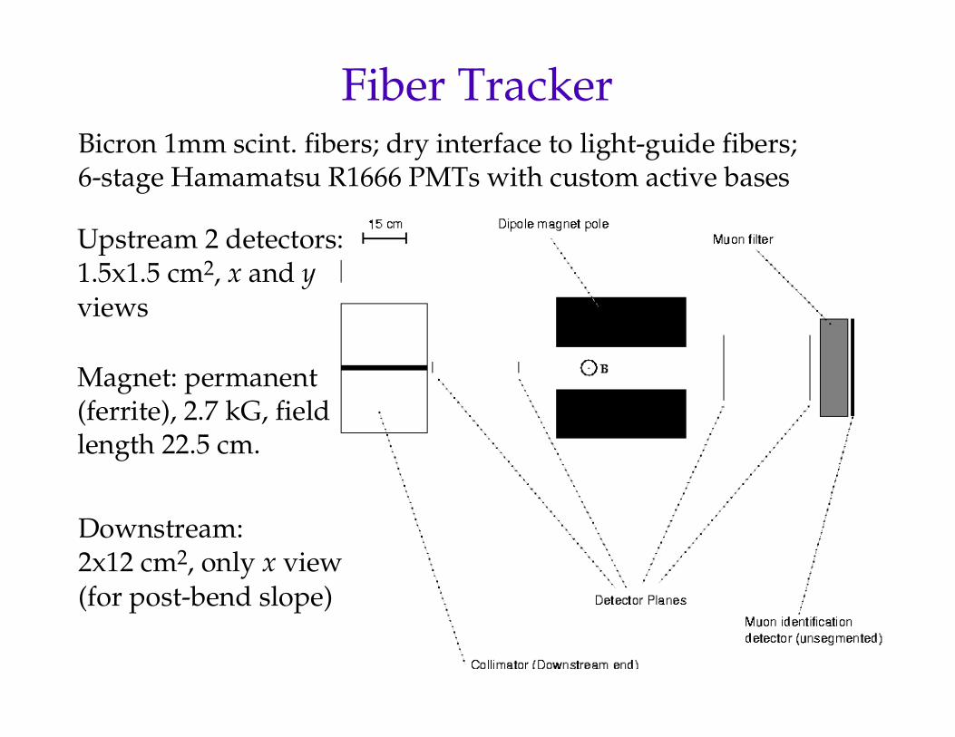
Fiber TrackerBicron 1mm scint. fibers; dry interface to light-guide fibers;6-stage Hamamatsu R1666 PMTs with custom active bases
Upstream 2 detectors:1.5x1.5 cm2, x and y views
Downstream:2x12 cm2, only x view(for post-bend slope)
Magnet: permanent(ferrite), 2.7 kG, fieldlength 22.5 cm.
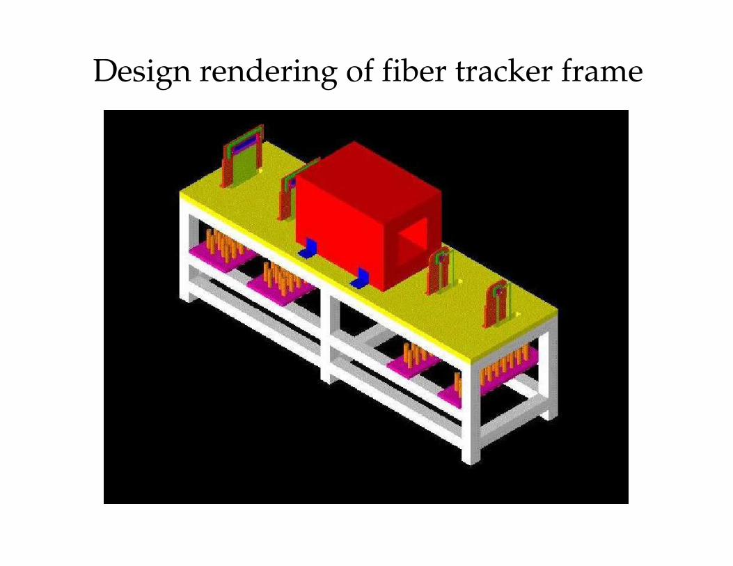
Design rendering of fiber tracker frame
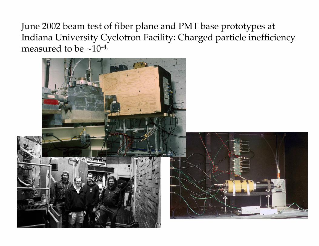
June 2002 beam test of fiber plane and PMT base prototypes atIndiana University Cyclotron Facility: Charged particle inefficiencymeasured to be ~10-4.
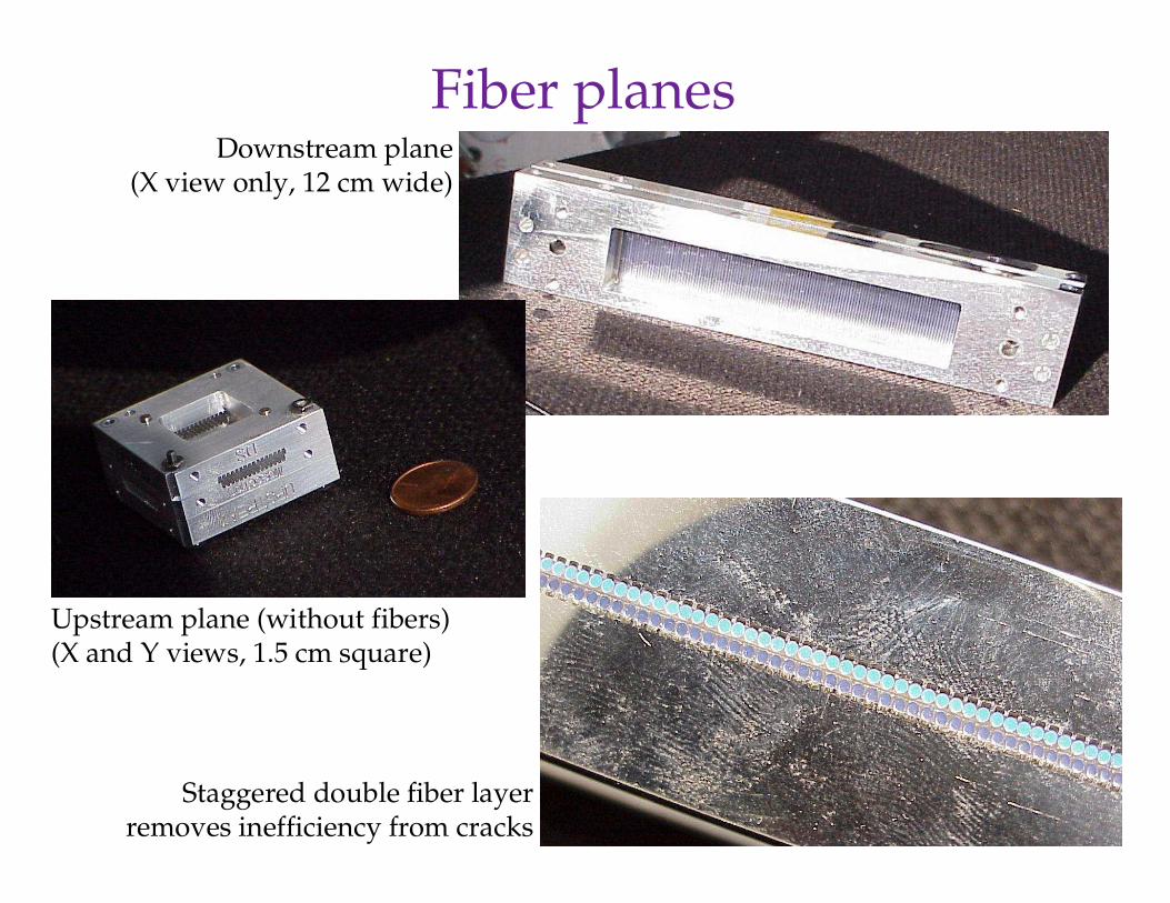
Fiber planesDownstream plane
(X view only, 12 cm wide)
Upstream plane (without fibers)(X and Y views, 1.5 cm square)
Staggered double fiber layerremoves inefficiency from cracks
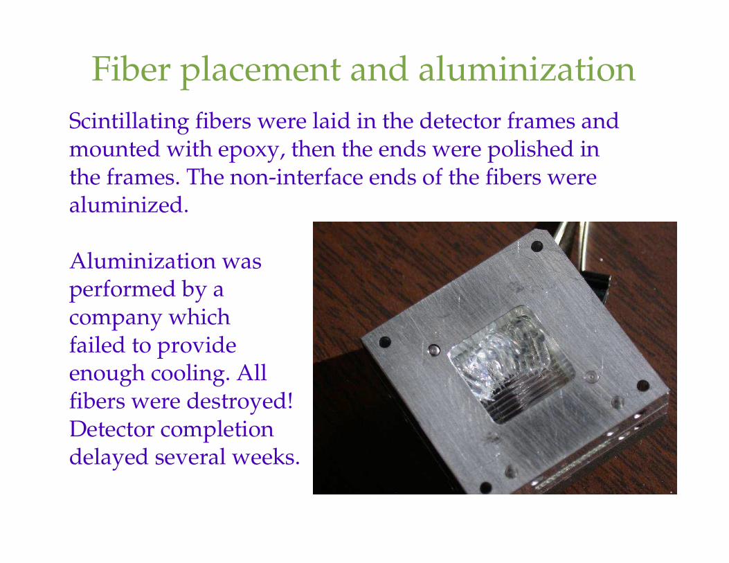
Fiber placement and aluminizationScintillating fibers were laid in the detector frames andmounted with epoxy, then the ends were polished inthe frames. The non-interface ends of the fibers werealuminized.
Aluminization wasperformed by a company which failed to provide enough cooling. All fibers were destroyed!Detector completiondelayed several weeks.
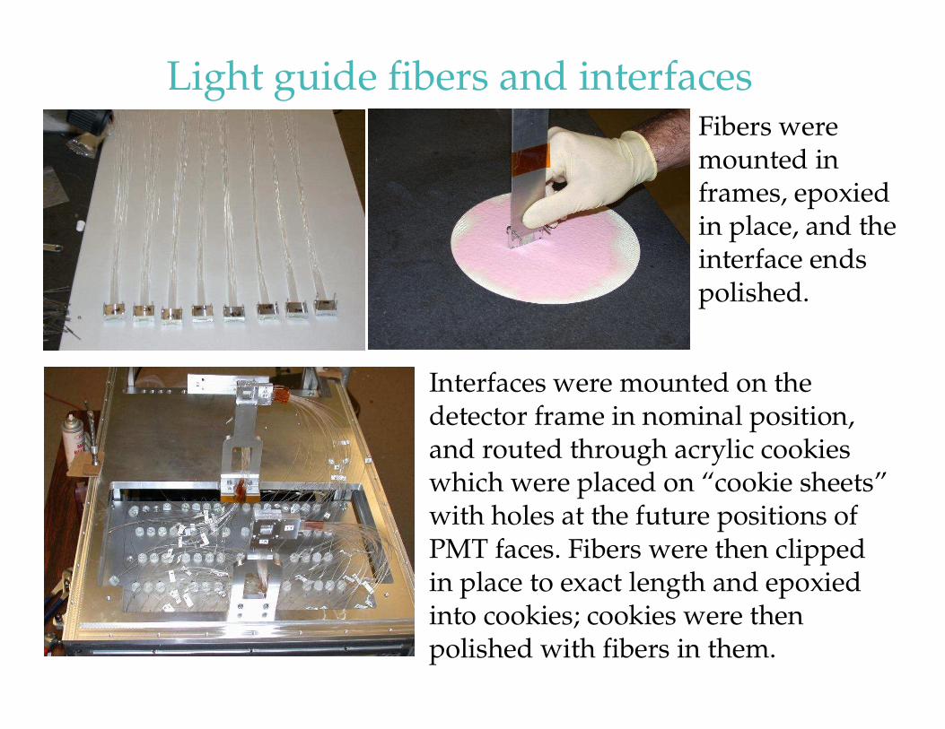
Light guide fibers and interfacesFibers were mounted in frames, epoxied in place, and the interface ends polished.
Interfaces were mounted on the detector frame in nominal position, and routed through acrylic cookies which were placed on “cookie sheets” with holes at the future positions of PMT faces. Fibers were then clipped in place to exact length and epoxied into cookies; cookies were then polished with fibers in them.
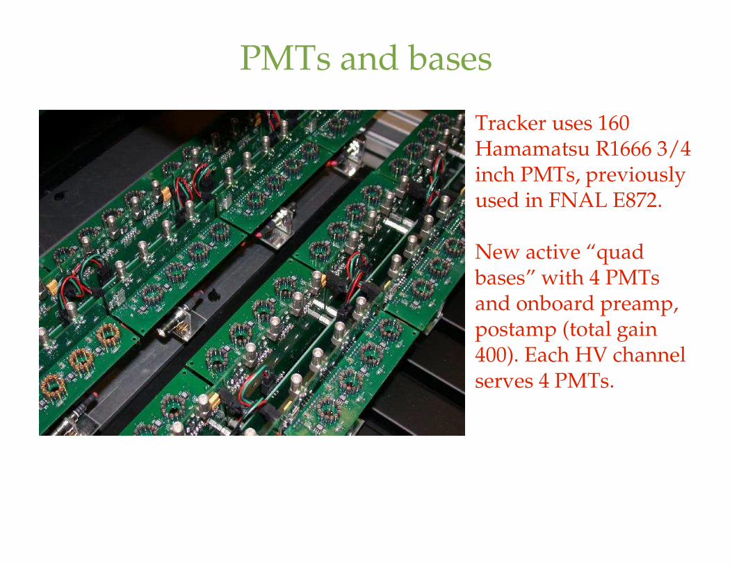
PMTs and bases
Tracker uses 160 Hamamatsu R1666 3/4 inch PMTs, previously used in FNAL E872.
New active “quad bases” with 4 PMTs and onboard preamp, postamp (total gain 400). Each HV channel serves 4 PMTs.

Road Trip!
EDZ drove the detector across the country to FNAL in a rented van in March 2003.
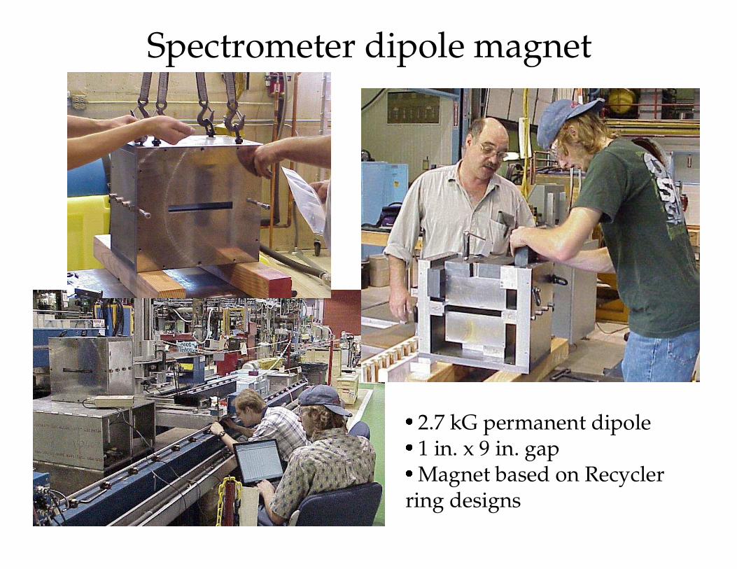
Spectrometer dipole magnet
� 2.7 kG permanent dipole
� 1 in. x 9 in. gap
� Magnet based on Recycler ring designs
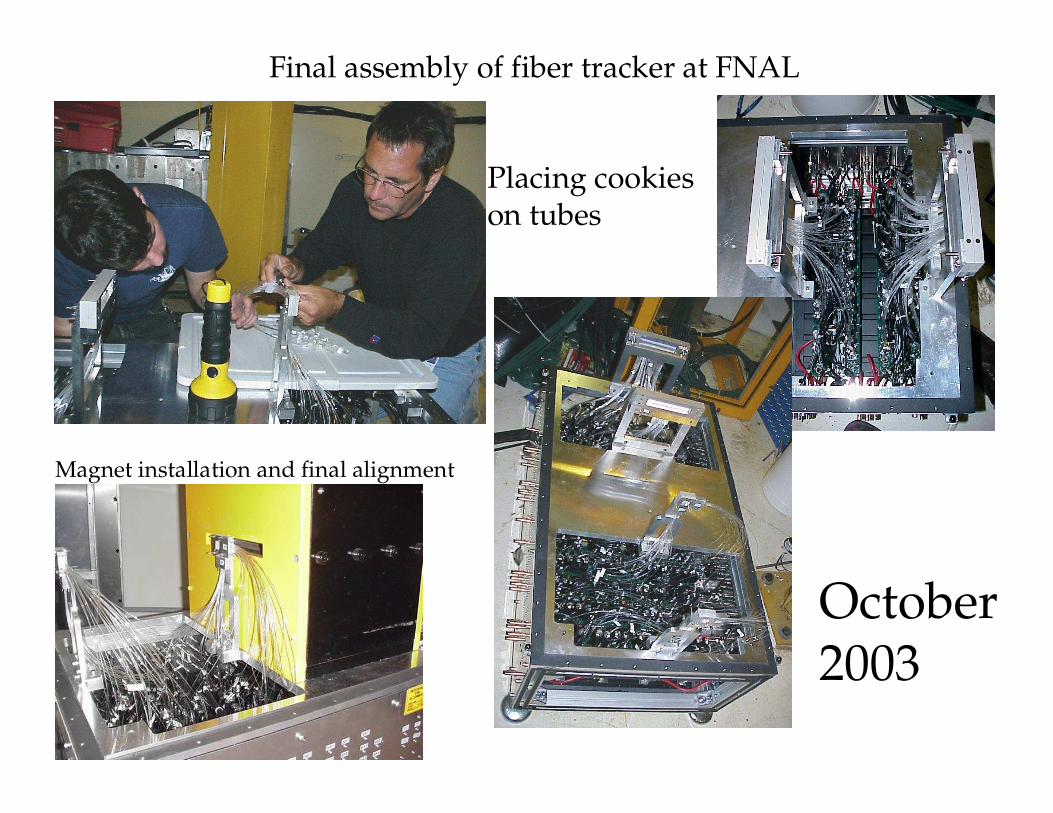
Final assembly of fiber tracker at FNAL
Placing cookies on tubes
Magnet installation and final alignment
October2003
Muon filter
�20 inch long, 8 inch square tungsten/scintillator range stack behind fiber tracker will identify muons.
�Expect µ/π ratio of order 2-4; most π are from Kl3 decay.
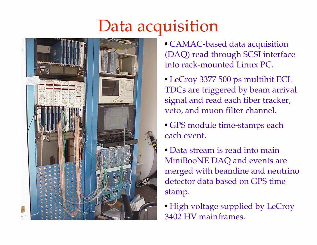
Data acquisition
� CAMAC-based data acquisition (DAQ) read through SCSI interface into rack-mounted Linux PC.
� LeCroy 3377 500 ps multihit ECL TDCs are triggered by beam arrival signal and read each fiber tracker, veto, and muon filter channel.
� GPS module time-stamps each each event.
� Data stream is read into main MiniBooNE DAQ and events are merged with beamline and neutrino detector data based on GPS time stamp.
� High voltage supplied by LeCroy 3402 HV mainframes.
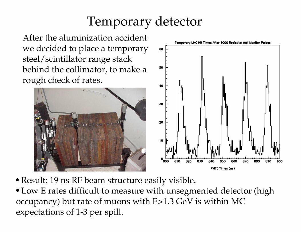
Temporary detectorAfter the aluminization accidentwe decided to place a temporarysteel/scintillator range stack behind the collimator, to make arough check of rates.
� Result: 19 ns RF beam structure easily visible.
� Low E rates difficult to measure with unsegmented detector (high occupancy) but rate of muons with E>1.3 GeV is within MC expectations of 1-3 per spill.
Status of the LMC
�
Major installation work during current accelerator shutdown
� Fiber tracker is operating -- expect first beam signals any day!
� Working on analysis code infrastructure
� Expect first LMC analysis in a few months.