Journal of Sound and Vibration - Wright State Universitycecs.wright.edu/~sheng.li/papers/A...
16
A tribo-dynamic model of a spur gear pair S. Li n , A. Kahraman Department of Mechanical and Aerospace Engineering, The Ohio State University, 201 W.19th Avenue, Columbus, OH 43210, USA article info Article history: Received 26 December 2012 Received in revised form 13 April 2013 Accepted 18 April 2013 Handling Editor: L.N. Virgin Available online 22 May 2013 abstract In this study, a tribo-dynamics model for spur gear pairs is proposed. The model couples a mixed elastohydrodynamic lubrication model of a spur gear pair with a transverse– torsional dynamic model. The lubrication model provides the dynamic model with friction forces and moments that couple the vibrations of the gears along the off-line-of-action direction to other gear vibrations. In addition, it predicts damping coefficient at the gear mesh in a physics-based manner from the energy loss associated with viscous shearing across the fluid film. In return, the dynamic model predicts the dynamic tooth forces and surface velocities to be used in the lubrication model. An iterative computational scheme is proposed to implement the lubrication and dynamics models simultaneously to couple tribological and dynamic behaviors of a spur gear pair fully. An example gear pair is analyzed using the proposed model to demonstrate this two-way relationship and quantify the impact of operating conditions, surface roughness and lubrication character- istics on the tribo-dynamics response. & 2013 Elsevier Ltd. All rights reserved. 1. Introduction Surfaces of contacting gear teeth are subject to combined rolling and sliding actions as gears rotate. The resultant rolling and sliding components of friction forces apply along the off-line-of-action (OLOA) direction (normal to the line-of-action (LOA) direction that is tangent to the base circles of gears) to form the main excitations for motions along the OLOA direction, at the same time producing friction moments acting in the torsional direction to couple OLOA and LOA motions. Additionally, power dissipation due to viscous shearing of the lubrication fluid film along the tooth contact interfaces is the main source of the gear mesh viscous damping [1], further coupling the LOA and OLOA motions. On the other hand, dynamic tooth forces and dynamic surface velocity fluctuations impact tribological behavior in terms of the contact pressure, film thickness, lubricant viscosity and the resultant friction forces [2]. This study aims at investigating such two-way interactions between gear dynamics and gear tribology by combining a multi-degree-of-freedom dynamic model and a transient mixed elastohydrodynamic lubrication (EHL) model into a single tribo-dynamics model for a spur gear pair. Over the past decades, a large number of gear dynamic models have been proposed as reviewed extensively by Ozguven and Houser [3] and more recently by Wang et al. [4]. These models vary in many aspects. Focusing on spur gears, single or multi-degree-of-freedom discrete models and finite element (FE) based deformable body models have been proposed. The published experimental data [5–13] indicate clearly that spur gear pairs act as nonlinear, time-varying systems due to the gear backlash and periodically varying gear mesh stiffness. Several discrete, nonlinear time varying (NTV) models were shown to correlate to such spur gear experiments well [8,9,14–17] in terms of torsional or LOA motions, provided the Contents lists available at SciVerse ScienceDirect journal homepage: www.elsevier.com/locate/jsvi Journal of Sound and Vibration 0022-460X/$ - see front matter & 2013 Elsevier Ltd. All rights reserved. http://dx.doi.org/10.1016/j.jsv.2013.04.022 n Corresponding author. Tel.: +1 614 247 8688; fax: +1 614 292 3163. E-mail address: [email protected] (S. Li). Journal of Sound and Vibration 332 (2013) 4963–4978
Transcript of Journal of Sound and Vibration - Wright State Universitycecs.wright.edu/~sheng.li/papers/A...
Contents lists available at SciVerse ScienceDirect
Journal of Sound and Vibration
Journal of Sound and Vibration 332 (2013) 4963–4978
0022-46http://d
n CorrE-m
journal homepage: www.elsevier.com/locate/jsvi
A tribo-dynamic model of a spur gear pair
S. Li n, A. KahramanDepartment of Mechanical and Aerospace Engineering, The Ohio State University, 201 W. 19th Avenue, Columbus, OH 43210, USA
a r t i c l e i n f o
Article history:Received 26 December 2012Received in revised form13 April 2013Accepted 18 April 2013
Handling Editor: L.N. Virgindirection to other gear vibrations. In addition, it predicts damping coefficient at the gear
Available online 22 May 2013
0X/$ - see front matter & 2013 Elsevier Ltd.x.doi.org/10.1016/j.jsv.2013.04.022
esponding author. Tel.: +1 614 247 8688; faail address: [email protected] (S. Li).
a b s t r a c t
In this study, a tribo-dynamics model for spur gear pairs is proposed. The model couples amixed elastohydrodynamic lubrication model of a spur gear pair with a transverse–torsional dynamic model. The lubrication model provides the dynamic model with frictionforces and moments that couple the vibrations of the gears along the off-line-of-action
mesh in a physics-based manner from the energy loss associated with viscous shearingacross the fluid film. In return, the dynamic model predicts the dynamic tooth forces andsurface velocities to be used in the lubrication model. An iterative computational schemeis proposed to implement the lubrication and dynamics models simultaneously to coupletribological and dynamic behaviors of a spur gear pair fully. An example gear pair isanalyzed using the proposed model to demonstrate this two-way relationship andquantify the impact of operating conditions, surface roughness and lubrication character-istics on the tribo-dynamics response.
& 2013 Elsevier Ltd. All rights reserved.
1. Introduction
Surfaces of contacting gear teeth are subject to combined rolling and sliding actions as gears rotate. The resultant rollingand sliding components of friction forces apply along the off-line-of-action (OLOA) direction (normal to the line-of-action(LOA) direction that is tangent to the base circles of gears) to form the main excitations for motions along the OLOAdirection, at the same time producing friction moments acting in the torsional direction to couple OLOA and LOA motions.Additionally, power dissipation due to viscous shearing of the lubrication fluid film along the tooth contact interfaces is themain source of the gear mesh viscous damping [1], further coupling the LOA and OLOA motions. On the other hand, dynamictooth forces and dynamic surface velocity fluctuations impact tribological behavior in terms of the contact pressure, filmthickness, lubricant viscosity and the resultant friction forces [2]. This study aims at investigating such two-way interactionsbetween gear dynamics and gear tribology by combining a multi-degree-of-freedom dynamic model and a transient mixedelastohydrodynamic lubrication (EHL) model into a single tribo-dynamics model for a spur gear pair.
Over the past decades, a large number of gear dynamic models have been proposed as reviewed extensively by Ozguvenand Houser [3] and more recently by Wang et al. [4]. These models vary in many aspects. Focusing on spur gears, single ormulti-degree-of-freedom discrete models and finite element (FE) based deformable body models have been proposed.The published experimental data [5–13] indicate clearly that spur gear pairs act as nonlinear, time-varying systems due tothe gear backlash and periodically varying gear mesh stiffness. Several discrete, nonlinear time varying (NTV) models wereshown to correlate to such spur gear experiments well [8,9,14–17] in terms of torsional or LOA motions, provided the
All rights reserved.
x: +1 614 292 3163.
Nomenclature
amax maximum half-Hertzian contact widthA area of a uniform EHL grid elementcm gear mesh dampingct torsional bearing dampingcxj; cyj bearing damping values of gear j, j¼ 1;2e error threshold for the iterationsf Eyring flow coefficientFbxj; Fbyj dynamic bearing forces of gear j, j¼ 1;2Fj total friction force on a contact of gear j,
j¼ 1;2Fr ; Fs rolling and sliding friction forces on a contact
of gear j, j¼ 1;2h fluid film thicknessJj polar mass moments of inertia of gear j, j¼ 1;2km gear mesh stiffnesskxj; kyj bearing stiffnesses of gear j, j¼ 1;2ℓ half-backlashLOA line of actionmj mass of gear j, j¼ 1;2n index for tooth pairs in contactN total number of tooth pairs in contactOLOA off-line-of-actionp contact pressurerj base radius of gear j, j¼ 1;2Rj radius of curvature of a contact of gear j,
j¼ 1;2SAP start of active profileSj surface roughness profile of a contact of gear j,
j¼ 1;2
t timeTj external torque applied to gear j, j¼ 1;2uj instantaneous surface velocity of a contact of
gear j (j¼ 1;2) in the direction of rollinguj nominal surface velocity of a contact of gear j
(j¼ 1;2) in the direction of rollingur rolling velocity at the lubricated contactus sliding velocity at the lubricated contactVðx; tÞ elastic deformation distribution at the lubri-
cated contactWm dynamic gear mesh forceWs
m quasi-static gear mesh forceWT dynamic normal tooth forceWs
T quasi-static normal tooth forcexj translation of gear j (j¼ 1;2) in the OLOA
directionyj translation of gear j (j¼ 1;2) in the LOA
directionZj number of teeth of gear j (j¼ 1;2)εs static transmission error of the gear pairεd dynamic transmission error of the gear pairη lubricant viscosityηn effective lubricant viscosityρ lubricant densityθj oscillating component of rotational displace-
ment of gear j, j¼ 1;2τ0 reference shear stress of the lubricantτv viscous shear stressτb boundary shear stressωj nominal rotational velocity of gear j, j¼ 1;2
S. Li, A. Kahraman / Journal of Sound and Vibration 332 (2013) 4963–49784964
viscous gear mesh damping value is adjusted to match the measurements. A typical gear mesh interface formulation ofthese models consists of four main components, all applied along the LOA direction: (i) a periodically time-varying gearmesh stiffness employed to represent the overall gear mesh flexibility including the compliances associated with thecontact, tooth bending, shear and base rotation of the gear teeth as well as the change of the number of tooth pairs incontact with rotation; (ii) a piecewise-linear clearance with a dead zone (backlash) to allow tooth separations; (iii) aperiodic external displacement excitation, often referred as the transmission error (TE) excitation, to take into account thedisturbances caused by intentional tooth profile modifications as well as unavoidable manufacturing deviations from theactual tooth profile; (iv) a viscous gear mesh damper to account for the energy loss at the gear mesh interface. Among thosefour components, the stiffness and transmission error functions can be predicted by using any gear contact or loaddistribution model [18,19] under quasi-static condition. The backlash magnitude can be determined from the effectivecenter distance and tooth thickness values. However, the value of the gear mesh damping coefficient is the least knownamongst gear dynamists. Almost all of the previous gear dynamic models use a constant viscous damping coefficient, statingthat it must be determined empirically. A wide range of gear mesh damping ratios were cited in the experimental geardynamics literature, ranging from as low as 1–2 percent [5,8–12] to as high as 10 percent [6,7]. Although the accuracy of thenatural frequencies and resonance frequencies would be influenced slightly by the actual value of damping ratio within thisrange, its impact on resonance peak amplitudes and the nonlinear behavior induced by backlash and parametric resonancesassociated with the time-varying gear mesh stiffness is critical [9,20,21]. Higher values of damping typically suppress bothnonlinear behavior and parametric sub-harmonic resonances, hence, dictating the response characteristics in terms of theseverity of nonlinear and sub-harmonic motions.
The gear dynamics models reviewed above excluded the friction at the gear tooth mesh interfaces, focusing solely on theLOA dynamic motions. Vaishya and Singh [22,23] included Coulomb friction as one of the excitations for the LOA dynamicbehavior in a single-degree-of-freedom formulation. Lundvall et al. [24] studied the impact of Coulomb friction on dynamicmotion considering a multi-degree-of-freedom system. Velex and Cahouet [25] examined the influence of sliding friction ondynamic bearing forces. Several recent studies including Kahraman et al. [26] and He et al. [27] investigated the OLOAvibrations of a spur gear pair that are caused by the friction at the gear mesh interface. In these models, either a simpleconstant friction coefficient or sliding friction formulae obtained from experiments or EHL models were used to determine
S. Li, A. Kahraman / Journal of Sound and Vibration 332 (2013) 4963–4978 4965
the motions along OLOA direction, which were uncoupled from those in the direction of LOA. All of these studies used auser-defined gear mesh damping element applied in the LOA direction as well.
Gear EHL models were proposed mostly for the purpose of gear mesh mechanical efficiency predictions [28–31] as wellas contact fatigue evaluations [32]. These EHL models include a set of quasi-static transient effects associated with thechange of tooth load, radii of contact curvature, rolling (mean) and sliding velocities as well as surface roughness profiles asthe contacts move along the tooth surfaces while assuming no dynamic effects. In a recent paper [2], these authors studiedthe impact of gear dynamics on the resultant tribological behavior using a purely torsional dynamic model of a gear pair topredict dynamic tooth forces to be considered by the gear EHL model. Ref. [2] focused solely on the effect of dynamicbehavior on gear tribology with effect of the EHL behavior on gear dynamics excluded. In a separate study [1], a theoreticalderivation of the gear mesh interface damping due to power dissipation caused by the EHL viscous shear stress and therelative motion between the lubrication film layers was proposed. This viscous gear mesh damper was shown to actuallyapply along the OLOA direction and impact the torsional motion through the moment exerted by the damper. The gear meshdamping was also shown to be proportional to the lubricant viscosity and inversely proportional to lubricant film thickness.
The review of the literature above indicates that there is no published work that combines a gear tribology model with agear dynamic model in a unified manner to capture mutual interactions amongst the two. Therefore, this study aims atdeveloping a tribo-dynamic model of a spur gear pair that is capable of including such key interactions. For this, atransverse–torsional dynamic model of a gear pair is combined with a mixed EHL model of a gear pair with all dynamictransient parameters included. Specific interactions captured in this tribo-dynamic model consist of the following:
�
Dynamic gear mesh tooth forces predicted by the dynamic model are used in the EHL model as the loading. � Surface velocity fluctuations due to gear vibrations are included in the EHL formulation in the definition of rolling andsliding velocities as well as non-Newtonian flow coefficients.
� A physics-based, time-varying, viscous gear mesh damping is defined from the EHL formulations to be used in thedynamic model along the OLOA direction. Since the EHL model considers rough surfaces, the roughness effects inaddition to the operating speed, load and temperature effects are all included in the gear mesh damping.
�
Time-varying friction forces acting in the OLOA direction and friction moments acting in torsional direction arecomputed from the EHL model to be used in the dynamic model to couple LOA and OLOA motions properly. Effects ofsurface roughness and operating speed, load and temperature conditions on this coupling are all captured through theEHL-based friction force formulations.An example six degree-of-freedom dynamic model and the gear mixed EHL model [33] are introduced in Sections 2.1 and2.2, respectively. They are combined into a unified model in Section 2.3 with the iterative procedure required to solve theunified model described in detail. Section 3 presents the example simulation results to demonstrate the coupled tribo-dynamic behavior under various operating conditions of speed and lubricant temperature, and surface conditions defined bymeasured surface roughness profiles (smooth vs. rough surfaces).
The dynamic model considered in this study is a transverse–torsional one that does not include axial and tilting (rocking)motions of gears, in line with the expected motions of spur gears. Yet the proposed methodology is general to allowreplacement of this dynamic model by a higher order discrete model or a deformable-body model. Likewise, the EHL modelused in this study is an isothermal one, focusing on inclusion of asperity contacts due to excessive surface roughness. Thegenerality of the proposed methodology allows other gear EHL models of varying sophistications, say ones with thermaleffects included, to be substituted in this methodology.
2. Model formulation
2.1. Discrete gear dynamics model
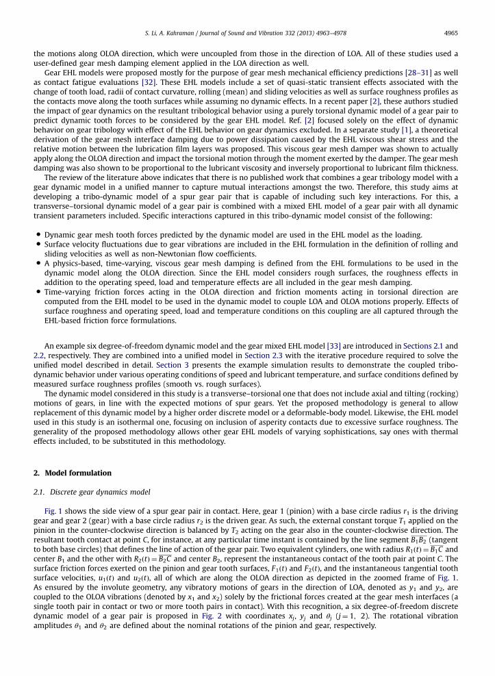
Fig. 1 shows the side view of a spur gear pair in contact. Here, gear 1 (pinion) with a base circle radius r1 is the drivinggear and gear 2 (gear) with a base circle radius r2 is the driven gear. As such, the external constant torque T1 applied on thepinion in the counter-clockwise direction is balanced by T2 acting on the gear also in the counter-clockwise direction. Theresultant tooth contact at point C, for instance, at any particular time instant is contained by the line segment B1B2 (tangentto both base circles) that defines the line of action of the gear pair. Two equivalent cylinders, one with radius R1ðtÞ ¼ B1C andcenter B1 and the other with R2ðtÞ ¼ B2C and center B2, represent the instantaneous contact of the tooth pair at point C. Thesurface friction forces exerted on the pinion and gear tooth surfaces, F1ðtÞ and F2ðtÞ, and the instantaneous tangential toothsurface velocities, u1ðtÞ and u2ðtÞ, all of which are along the OLOA direction as depicted in the zoomed frame of Fig. 1.As ensured by the involute geometry, any vibratory motions of gears in the direction of LOA, denoted as y1 and y2, arecoupled to the OLOA vibrations (denoted by x1 and x2) solely by the frictional forces created at the gear mesh interfaces (asingle tooth pair in contact or two or more tooth pairs in contact). With this recognition, a six degree-of-freedom discretedynamic model of a gear pair is proposed in Fig. 2 with coordinates xj, yj and θj (j¼ 1; 2). The rotational vibrationamplitudes θ1 and θ2 are defined about the nominal rotations of the pinion and gear, respectively.
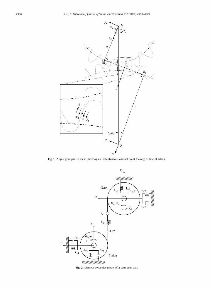
Fig. 1. A spur gear pair in mesh showing an instantaneous contact point C along its line of action.
Fig. 2. Discrete dynamics model of a spur gear pair.
S. Li, A. Kahraman / Journal of Sound and Vibration 332 (2013) 4963–49784966
S. Li, A. Kahraman / Journal of Sound and Vibration 332 (2013) 4963–4978 4967
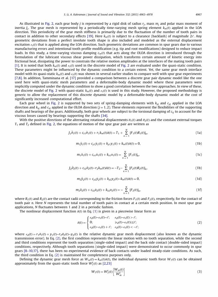
As illustrated in Fig. 2, each gear body j is represented by a rigid disk of radius rj, mass mj and polar mass moment ofinertia Jj. The gear mesh is represented by a periodically time-varying mesh spring element kmðtÞ applied in the LOAdirection. This periodicity of the gear mesh stiffness is primarily due to the fluctuation of the number of tooth pairs incontact in addition to other secondary effects [19]. Here kmðtÞ is subject to a clearance (backlash) of magnitude 2ℓ. Anygeometric deviations from a perfect involute tooth shape is also included and modeled as the external displacementexcitation εsðtÞ that is applied along the LOA direction. Such geometric deviations are common in spur gears due to variousmanufacturing errors and intentional tooth profile modification (e.g. tip and root modifications) designed to reduce impactloads. In this study, a time-varying viscous damping cmðtÞ that acts along the OLOA direction is introduced through theformulation of the lubricant viscous shear power dissipation, which transforms certain amount of kinetic energy intofrictional heat, dissipating the power to constrain the relative motion amplitudes at the interfaces of the mating tooth pairs[1]. It is noted that both kmðtÞ and εsðtÞ used in the discrete model of Fig. 2 are evaluated under the quasi-static condition.These parameters might be influenced by the dynamic condition to a certain extent. Yet, the same gear mesh interfacemodel with its quasi-static kmðtÞ and εsðtÞ was shown in several earlier studies to compare well with spur gear experiments[7,8]. In addition, Tamminana et al. [17] provided a comparison between a discrete gear pair dynamic model like the oneused here with quasi-static mesh parameters and a deformable-body dynamic model where these parameters wereimplicitly computed under the dynamic condition to show a good correlation between the two approaches. In view of these,the discrete model of Fig. 2 with quasi-static kmðtÞ and εsðtÞ is used in this study. However, the proposed methodology isgeneric to allow the replacement of this discrete dynamic model by a deformable-body dynamic model at the cost ofsignificantly increased computational effort.
Each gear wheel in Fig. 2 is supported by two sets of spring-damping elements with kyj and cyj applied in the LOAdirection and kxj and cxj applied in the OLOA direction (j¼ 1;2). These elements represent the flexibilities of the supportingshafts and bearings of the gears. Additionally, both gear wheels are subject to the torsional damping of ctj to account for theviscous losses caused by bearings supporting the shafts [34].
With the positive directions of the alternating rotational displacements θ1ðtÞ and θ2ðtÞ and the constant external torquesT1 and T2 defined in Fig. 2, the equations of motion of the spur gear pair are written as
J1 €θ1ðtÞ þ ct1 _θ1ðtÞ þ r1kmðtÞδðtÞ ¼ T1 þ ∑N
n ¼ 1½F1ðtÞR1ðtÞ�n; (1a)
m1 €y1ðtÞ þ cy1 _y1ðtÞ þ ky1y1ðtÞ þ kmðtÞδðtÞ ¼ 0; (1b)
m1 €x1ðtÞ þ cx1 _x1ðtÞ þ kx1x1ðtÞ ¼ ∑N
n ¼ 1½F1ðtÞ�n; (1c)
J2 €θ2ðtÞ þ ct2 _θ2ðtÞ−r2kmðtÞδðtÞ ¼−T2− ∑N
n ¼ 1½F2ðtÞR2ðtÞ�n; (1b)
m2 €y2ðtÞ þ cy2 _y2ðtÞ þ ky2y2ðtÞ−kmðtÞδðtÞ ¼ 0; (1d)
m2 €x2ðtÞ þ cx2 _x2ðtÞ þ kx2x2ðtÞ ¼ − ∑N
n ¼ 1½F2ðtÞ�n; (1f)
where R1ðtÞ and R2ðtÞ are the contact radii corresponding to the friction forces F1ðtÞ and F2ðtÞ, respectively, for the contact oftooth pair n. Here N represents the total number of tooth pairs in contact at a certain mesh position. In most spur gearapplications, N fluctuates between 1 and 2 in a periodic fashion.
The nonlinear displacement function δðtÞ in Eq. (1) is given in a piecewise linear form as
δðtÞ ¼εdðtÞ−εsðtÞ−ℓ; εdðtÞ−εsðtÞ4ℓ;
0; jεdðtÞ−εsðtÞj≤ℓ;εdðtÞ−εsðtÞ þ ℓ; εdðtÞ−εsðtÞo−ℓ;
8><>: (2)
where εdðtÞ ¼ r1θ1ðtÞ þ y1ðtÞ−r2θ2ðtÞ−y2ðtÞ is the relative dynamic gear mesh displacement (also known as the dynamictransmission error). In Eq. (2), the first condition represents the linear motion with no tooth separation, while the secondand third conditions represent the tooth separation (single-sided impact) and the back side contact (double-sided impact)conditions, respectively. Although tooth separations (single-sided impact) were demonstrated to occur commonly in spurgears [8–10,17], there has been no experimental evidence of back contacts under loaded steady-state conditions. As such,the third condition in Eq. (2) is maintained for completeness purposes only.
Defining the dynamic gear mesh force as WmðtÞ ¼ kmðtÞδðtÞ, the individual dynamic tooth force WT ðtÞ can be obtainedapproximately from the quasi-static tooth force Ws
T ðtÞ as [2,23]
WT ðtÞ ¼WsT ðtÞ
WmðtÞWs
m
� �(3)
S. Li, A. Kahraman / Journal of Sound and Vibration 332 (2013) 4963–49784968
where Wsm ¼ T1=r1 is the total static mesh force transmitted and Ws
T ðtÞ is determined using a gear load distribution model[18,19]. This dynamic tooth force is used in the EHL analysis to determine the transient tooth friction forces F1ðtÞ and F2ðtÞ aswell as the gear mesh viscous damping magnitude, in the process capturing the most critical influence of the dynamicbehavior on the lubrication characteristics. The dynamic bearing forces in the LOA and OLOA directions are definedrespectively as FbyjðtÞ ¼ kyjyjðtÞ þ cyj _yjðtÞ and FbxjðtÞ ¼ kxjxjðtÞ þ cxj _xjðtÞ, j¼ 1;2.
2.2. EHL-based gear mesh friction and viscous damping formulations
Velocity of a tooth surface contact point consists of a kinematic component due to the nominal rotation of the gears and afluctuating (dynamic) component due to the vibratory torsional and translational motions. For an arbitrary tooth pair incontact, the instantaneous tangential surface velocities of the pinion and gear are
u1ðtÞ ¼ u1ðtÞ þ R1ðtÞ_θ1ðtÞ−_x1ðtÞ; (4a)
u2ðtÞ ¼ u2ðtÞ þ R2ðtÞ_θ2ðtÞ−_x2ðtÞ (4b)
where u1ðtÞ ¼ R1ðtÞω1 and u2ðtÞ ¼ R2ðtÞω2 are the kinematic surface velocities of the pinion and the gear that are rotating atthe angular velocities of ω1 and ω2 ¼ Z1ω1=Z2 as shown in Fig. 2 with Z1 and Z2 being the numbers of teeth of the pinion andthe gear. It is noted in Eq. (4) that ½R1ðtÞ_θ1ðtÞ−_x1ðtÞ� and ½R2ðtÞ_θ2ðtÞ−_x2ðtÞ� represent another influence of the vibratory motionson the EHL behavior of spur gear contacts in addition to the dynamic tooth force. These vibratory components of the surfacevelocities are observed to have a secondary influence on the overall EHL behavior. They are included in Eq. (4) forcompleteness purposes.
The movement of the tooth surfaces that are in mesh entrains the lubricant into the contact. Depending on the operatingconditions including speed, load, temperature and surface roughness conditions, the lubrication conditions range from fullfilm to mixed or even boundary regimes for most of the automotive and aerospace gearing applications. Under the mixedlubrication regime, the hydrodynamic viscous fluid film and asperity contacts coexist. Characterizing the tooth contact ofspur gears as a line contact [29–33], the fluid flow within the contact zone is governed by the one dimensional transientReynolds equation of
∂∂x
f ðx; tÞ ∂pðx; tÞ∂x
� �¼ urðtÞ
∂½ρðx; tÞhðx; tÞ�∂x
þ ∂½ρðx; tÞhðx; tÞ�∂t
(5a)
where pðx; tÞ, hðx; tÞ and ρðx; tÞ are the transient pressure, fluid film thickness and density distributions along the rolling (off-line-of-action) direction x as depicted in Fig. 1 at a time instant t. Here urðtÞ is the rolling velocity that is defined as urðtÞ ¼ 1
2 u1ðtÞ þ u2ðtÞ½ �.The Eyring flow coefficient f ðx; tÞ is approximated as f ðx; tÞ ¼ fρðx; tÞhðx; tÞ3=½12ηðx; tÞ�gcosh½τmðx; tÞ=τ0� [29–33], where ηðx; tÞ is thelubricant viscosity, τ0 is the lubricant reference stress, and τmðx; tÞ ¼ τ0sinh
−1fηðx; tÞusðtÞ=½τ0hðx; tÞ�g is the mean viscous shear stresswith the sliding velocity defined as usðtÞ ¼ u1ðtÞ−u2ðtÞ. For any local asperity contact spots, where the fluid film is too thin to allowany hydrodynamic lubrication, the reduced form of the Reynolds equation is used to describe the contact:
urðtÞ∂hðx; tÞ
∂xþ ∂hðx; tÞ
∂t¼ 0: (5b)
Limiting the analysis to elastic deformations only, the transient local film thickness can be defined as
hðx; tÞ ¼ h0ðtÞ þ g0ðx; tÞ þ Vðx; tÞ−S1ðx; tÞ−S2ðx; tÞ (6)
where h0ðtÞ is the reference film thickness, Vðx; tÞ represents the surface elastic deflection, and g0ðx; tÞ ¼ x2=½2ReqðtÞ� is theunloaded geometric gap between the mating tooth surfaces, which is time dependent through the variable equivalent radiusof curvature ReqðtÞ ¼ ½1=R1ðtÞ þ 1=R2ðtÞ�−1. The S1ðx; tÞ and S2ðx; tÞ terms are the tooth surface roughness profiles measured inthe profile (rolling and sliding) direction. Here, it is assumed that these roughness profiles remain constant along the toothface direction to be in agreement with a line contact assumption, which is reasonable for most gear finishing processes suchas grinding and shaving. Relationships provided in Refs. [31,35] are employed for the description of the pressuredependence of lubricant viscosity and density.
The viscous shear stress within the lubricant varies linearly along the film thickness direction z. With both Poiseuille andCouette flows included, this viscous shear is written as [30]
τvðx; z; tÞ ¼ ηnðx; tÞhðx; tÞ u2ðtÞ−u1ðtÞ½ � þ z−
12hðx; tÞ ∂pðx; tÞ
∂x(7)
where the Eyring fluid effective viscosity ηnðx; tÞ ¼ ηðx; tÞ=coshðτmðx; tÞ=τ0Þ takes into account the non-Newtonian effects.From Eq. (7), τv1ðx; tÞ ¼ τvðx;0; tÞ and τv2ðx; tÞ ¼ τvðx;h; tÞ are arrived as the viscous shear stresses acting on the pinion and geartooth surfaces at z¼0 and z¼h, respectively, as
τv1ðx; tÞ ¼ηnðx; tÞhðx; tÞ u2ðtÞ−u1ðtÞ½ �−1
2hðx; tÞ ∂pðx; tÞ
∂x; (8a)
S. Li, A. Kahraman / Journal of Sound and Vibration 332 (2013) 4963–4978 4969
τv2ðx; tÞ ¼ηnðx; tÞhðx; tÞ u2ðtÞ−u1ðtÞ½ � þ 1
2hðx; tÞ ∂pðx; tÞ
∂x(8b)
Within the regions where asperity contacts take place, the boundary shear stress is determined as the product of thelocal contact pressure and the boundary friction coefficient μb as τbðx; tÞ ¼ μbpðx; tÞ.
Details of the discretization and computational schemes employed to solve the above governing equations to find τv1ðx; tÞ,τv2ðx; tÞ and τbðx; tÞ as the contact point Cmoves along the LOA direction defined by the line segment B1B2 can be found in Ref.[33]. Defining a computational domain of −2:5amax≤x≤1:5amax in the direction of rolling (x direction) where amax is themaximum half-Hertzian width of the contacts along the entire line-of-action and applying a refined mesh with I gridelements, the shear stresses at each grid node are then determined by using this model as τv1ðxi; tÞ ¼ τv1iðtÞ, τv2ðxi; tÞ ¼ τv2iðtÞ andτbðxi; tÞ ¼ τbi ðtÞ (i∈½1; I�).
Denoting the area of each uniform tooth surface EHL grid element as A, the total friction forces exerted on the surfaces ofan arbitrary contacting tooth pair are written as
F1ðtÞ ¼ A ∑I
i ¼ 1½τv1iðtÞ þ τbi ðtÞ�; (9a)
F2ðtÞ ¼ A ∑I
i ¼ 1½τv2iðtÞ þ τbi ðtÞ� (9b)
Here, τv1iðtÞ ¼ τv2iðtÞ ¼ 0 for grid nodes experiencing asperity contacts and τbi ðtÞ ¼ 0 for grid nodes separated by fluid film.Substituting Eqs. (4) and (8) into Eq. (9), the following expressions for the friction forces acting on the tooth pair areobtained as
F1ðtÞ ¼ cmðtÞ½R2ðtÞ_θ2ðtÞ−_x2ðtÞ−R1ðtÞ_θ1ðtÞ þ _x1ðtÞ� þ FsðtÞ−FrðtÞ; (10a)
F1ðtÞ ¼ cmðtÞ½R2ðtÞ_θ2ðtÞ−_x2ðtÞ−R1ðtÞ_θ1ðtÞ þ _x1ðtÞ� þ FsðtÞ þ FrðtÞ (10b)
where the gear mesh viscous damping cmðtÞ, the sliding friction force FsðtÞ and the rolling friction force FrðtÞ are defined as
cmðtÞ ¼ A ∑I
i ¼ 1
ηnðxi; tÞhðxi; tÞ
� �; (10c)
Fig. 3. Flowchart of the computational method used to implement the solution for the proposed gear tribo-dynamics model.
S. Li, A. Kahraman / Journal of Sound and Vibration 332 (2013) 4963–49784970
FsðtÞ ¼ A ∑I
i ¼ 1τbi ðtÞ þ A ∑
I
i ¼ 1
ηnðxi; tÞhðxi; tÞ
u2ðtÞ−u1ðtÞ½ �� �
; (10d)
FrðtÞ ¼ A ∑I
i ¼ 1
12hðxi; tÞ
∂pðxi; tÞ∂x
� �(10e)
It is seen that the gear mesh viscous damping term is directly proportional to the lubricant viscosity and inverselyproportional to the film thickness. Since the lubricant viscosity varies exponentially with pressure [1,2,29–33] and thecontact pressure changes with the mesh position as the gears roll, the viscous damper defined above becomes a time-varying parameter with the period equal to the gear mesh period. Through the introduction of local pressure fluctuations,surface roughness amplitudes also influence this damping magnitude. In addition, the surface velocities and the lubricanttemperature (through its influence on the oil viscosity) dictate the film thickness, causing cmðtÞ to be impacted by theoperating speed and temperature conditions.
2.3. Tribo-dynamic model of spur gear pairs
Substituting Eq. (10) into Eq. (1), the equations of motion become
J1 €θ1ðtÞ þ ct1 þ ∑N
n ¼ 1R21ðtÞcmðtÞ
h in
� �_θ1ðtÞ− ∑
N
n ¼ 1½R1ðtÞR2ðtÞcmðtÞ�n _θ2ðtÞ
− ∑N
n ¼ 1½R1ðtÞcmðtÞ�n½_x1ðtÞ−_x2ðtÞ� þ r1kmðtÞδðtÞ ¼ T1 þ ∑
N
n ¼ 1f½FsðtÞ−FrðtÞ�R1ðtÞgn; (11a)
m1 €y1ðtÞ þ cy1 _y1ðtÞ þ ky1y1ðtÞ þ kmðtÞδðtÞ ¼ 0; (11b)
m1 €x1ðtÞ− ∑N
n ¼ 1½R1ðtÞcmðtÞ�n _θ1ðtÞ þ ∑
N
n ¼ 1½R2ðtÞcmðtÞ�n _θ2ðtÞ
Table 1Basic design parameters of the example spur gears considered in this study [17].
Number of teeth 50Module [mm] 3.0Pressure angle [deg] 20.0Pitch diameter [mm] 150.0Base diameter [mm] 140.95Outside diameter [mm] 156.0Root diameter [mm] 140.0Circular tooth thickness [mm] 4.64Face width [mm] 20.0Center distance [mm] 150.0
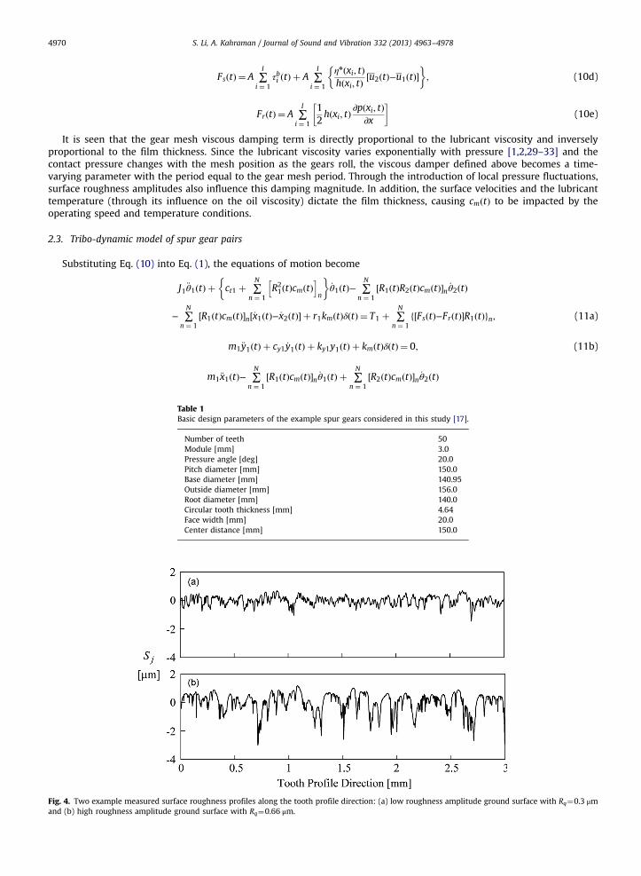
Fig. 4. Two example measured surface roughness profiles along the tooth profile direction: (a) low roughness amplitude ground surface with Rq¼0.3 μmand (b) high roughness amplitude ground surface with Rq¼0.66 μm.
S. Li, A. Kahraman / Journal of Sound and Vibration 332 (2013) 4963–4978 4971
þ cx1 þ ∑N
n ¼ 1½cmðtÞ�n
� �_x1ðtÞ− ∑
N
n ¼ 1½cmðtÞ�n _x2ðtÞ þ kx1x1ðtÞ ¼ ∑
N
n ¼ 1½FsðtÞ−FrðtÞ�n; (11c)
J2 €θ2ðtÞ− ∑N
n ¼ 1½R1ðtÞR2ðtÞcmðtÞ�n _θ1ðtÞ þ ct2 þ ∑
N
n ¼ 1½R2
2ðtÞcmðtÞ�n� �
_θ2ðtÞ
þ ∑N
n ¼ 1½R2ðtÞcmðtÞ�n½_x1ðtÞ−_x2ðtÞ�−r2kmðtÞδðtÞ ¼ −T2− ∑
N
n ¼ 1f½FsðtÞ þ FrðtÞ�R2ðtÞgn; (11d)
m2 €y2ðtÞ þ cy2 _y2ðtÞ þ ky2y2ðtÞ−kmðtÞδðtÞ ¼ 0; (11e)
m2 €x2ðtÞ þ ∑N
n ¼ 1½R1ðtÞcmðtÞ�n _θ1ðtÞ− ∑
N
n ¼ 1½R2ðtÞcmðtÞ�n _θ2ðtÞ
− ∑N
n ¼ 1½cmðtÞ�n _x1ðtÞ þ cx2 þ ∑
N
n ¼ 1½cmðtÞ�n
� �_x2ðtÞ þ kx2x2ðtÞ ¼ − ∑
N
n ¼ 1½FsðtÞ þ FrðtÞ�n: (11f)
Eq. (11) indicates clearly that gear tooth mesh damping acts along the OLOA direction. cmðtÞ not only contributes to theOLOA motions in Eq. (11c,f), but also couples the dynamic responses along the OLOA direction with LOA motions in Eq. (9a,c,d,f). It is also noted that the OLOA translations, x1ðtÞ and x2ðtÞ, are further coupled to the rotational motions, θ1ðtÞand θ2ðtÞ,though the friction forces and moments. None of these effects were included in previous gear dynamics models of this kind.
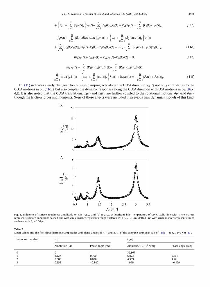
Fig. 5. Influence of surface roughness amplitude on (a) ðεdÞrms and (b) ðFbyÞrms at lubricant inlet temperature of 90 1C. Solid line with circle markerrepresents smooth condition; dashed line with circle marker represents rough surfaces with Rq¼0.3 μm; dotted line with circle marker represents roughsurfaces with Rq¼0.66 μm.
Table 2Mean values and the first three harmonic amplitudes and phase angles of εsðtÞ and kmðtÞ of the example spur gear pair of Table 1 at T1¼340 Nm [19].
harmonic number εsðtÞ kmðtÞ
Amplitude [μm] Phase angle [rad] Amplitude [�107 N/m] Phase angle [rad]
0 0 — 32.867 —
1 2.327 0.760 6.873 0.7612 0.008 0.836 4.339 1.5213 0.256 −0.840 1.999 −0.859
S. Li, A. Kahraman / Journal of Sound and Vibration 332 (2013) 4963–49784972
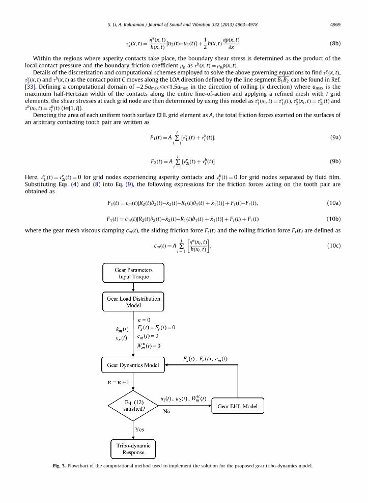
The computational method for the gear tribo-dynamics formulation proposed above consists of an iteration loopbetween the gear dynamics model and the gear EHL model as illustrated in Fig. 3. Before the iteration starts, a quasi-staticgear load distribution model [19] is used to determine kmðtÞ and εsðtÞ. with the gear parameters and the external torques asthe inputs. The initial values of sliding and rolling friction forces and gear mesh damping at the beginning of this iterativesolution process (iteration index κ¼ 0) are set as FsðtÞ ¼ 0, FrðtÞ ¼ 0 and cmðtÞ ¼ 0, respectively. With these excitations, thedynamics model of Eq. (11) predicts the vibratory motions from which the instantaneous surface velocities u1ðtÞ and u2ðtÞare found according to Eq. (4). Likewise, the dynamic mesh force WmðtÞ ¼ kmðtÞδðtÞ is computed from the same vibrationresponse and substituted into Eq. (3) to find dynamic tooth forces WT ðtÞ. These WT ðtÞ, u1ðtÞ and u2ðtÞ values are used in thegear EHL model to determine FsðtÞ and FrðtÞ as well as cmðtÞ of each tooth pair n. These gear tooth excitations together withkmðtÞ and εsðtÞ are then fed back into the gear dynamics model to predict the updated dynamic responses. This iterationbetween the dynamic model and the EHL model are repeated until the convergence criterion
∑γ jWκmðtγÞ−Wκ−1
m ðtγÞj∑γW
κmðtγÞ
oe (12)
is satisfied. Here, the dynamic gear mesh force is chosen for the convergence check since it is a common parameterrepresenting both EHL and dynamic model solutions. All other relevant parameters such as friction forces and damping arealso observed to converge once this criterion of convergence is met. In Eq. (12), index γ denotes the mesh position withinone mesh cycle and e is the user-defined error threshold (e¼ ð10Þ−5 was found to be sufficient for the example analysispresented in the next section).
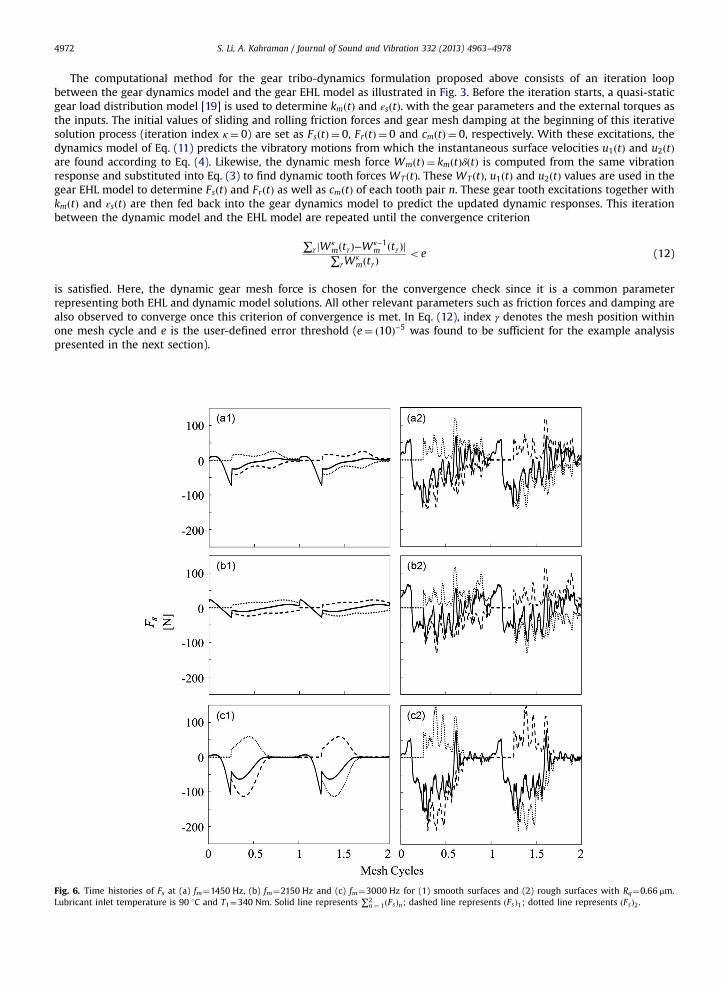
Fig. 6. Time histories of Fs at (a) fm¼1450 Hz, (b) fm¼2150 Hz and (c) fm¼3000 Hz for (1) smooth surfaces and (2) rough surfaces with Rq¼0.66 μm.Lubricant inlet temperature is 90 1C and T1¼340 Nm. Solid line represents ∑2
n ¼ 1ðFsÞn; dashed line represents ðFsÞ1; dotted line represents ðFsÞ2.
S. Li, A. Kahraman / Journal of Sound and Vibration 332 (2013) 4963–4978 4973
3. Results and discussion
A unity-ratio spur gear pair that was previously used in various gear dynamics experiments [8–13,17] is employed here as theexample system. The basic design parameters of the gear pair are listed in Table 1. Both gears have a tip relief of 0.01 mm starting atthe pitch point (corresponding to the roll angle of 20.91). The gear pair is operated at a fixed center distance of 150.0 mm such thatthe profile contact ratio of the spur gear pair is 1.75. This means that there are about 1.75 tooth pairs in contact on an average, i.e.there are two tooth pairs in contact during the three-fourths of the meshing period. The equivalent bearing stiffness and dampingvalues are estimated as ky¼1.15(10)9 N/m and cy¼5360 Ns/m in the LOA direction (corresponding to a damping ratio of about0.03), and kx ¼ 8:0ð10Þ8 kx¼8.0(10)8 N/m and cx¼2980 Ns/m (corresponding to a damping ratio of about 0.02) in the OLOAdirection for both the pinion and the gear. The torsional bearing damping value is assumed to be ct¼10 Nms/rad. A typicalaerospace gear fluid Mil-L23699 is used as the lubricant, whose mechanical properties can be found in Refs. [31,35]. Three differentsurface roughness conditions are considered in this work, namely, perfectly smooth surfaces, low-roughness-amplitude groundtooth surfaces with root-mean-square (rms) roughness amplitude of Rq≈0:3 μm (representative of the measured roughness traceshown in Fig. 4(a)) and high-roughness-amplitude ground tooth surfaces with Rq¼0.66 μm (Fig. 4(b)). These roughness profiles areall measured along the tooth profile (rolling and sliding) direction.
It is noted that no attempt is made here to compare the predictions of the proposed model to those assuming a constantfriction coefficient. The work of Xu et al. [28] compared the impacts of different friction models on power losses to indicatethat the constant friction coefficient assumption is not accurate through comparisons to benchmark experiments. LikewiseHe et al. [27] investigated the consequences of different friction models on off-line-of-action vibrations of a spur gear pair toshow that a constant friction coefficient is not sufficient for an accurate description of the dynamic response. Alsoconsidering the recent studies of these authors [1,2] which showed the clear impact of dynamics on EHL behavior of gearsand the origin of gear mesh damping, the limiting cases with constant friction coefficient are not considered in this study.
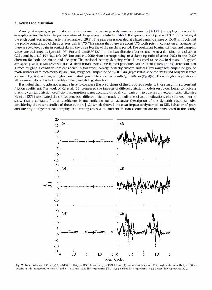
Fig. 7. Time histories of Fr at (a) fm¼1450 Hz, (b) fm¼2150 Hz and (c) fm¼3000 Hz for (1) smooth surfaces and (2) rough surfaces with Rq¼0.66 μm.Lubricant inlet temperature is 90 1C and T1¼340 Nm. Solid line represents ∑2
n ¼ 1ðFrÞn; dashed line represents ðFrÞ1; dotted line represents ðFrÞ2.
S. Li, A. Kahraman / Journal of Sound and Vibration 332 (2013) 4963–49784974
Using the tribo-dynamics model presented in Section 2, the dynamic responses in the forms of the rms dynamictransmission error ðεdÞrms ¼
ffiffiffiffiffiffiffiffiffiffiffiffiffiffiffiffiffiffiffi∑Q
q ¼ 1ε2dq
q(εdq is the qth harmonic amplitude of εdðtÞ) and LOA bearing forces
ðFbyÞrms ¼ffiffiffiffiffiffiffiffiffiffiffiffiffiffiffiffiffiffiffiffiffiffi∑Q
q ¼ 1F2byq
q(Fbyq is the qth harmonic amplitude of FbyðtÞ) are compared for the three roughness conditions
under the operating condition of T1¼340 Nm, lubricant inlet temperature of 90 1C and rotational speed Ω1 ranging from600 rev/min to 4200 rev/min (corresponding to the mesh frequency range of 500 Hz≤f m≤3500 Hz) in Fig. 5. The meanvalues and first three harmonic amplitudes of εsðtÞ and kmðtÞ as listed in Table 2 are considered here for this example gearpair. It is observed in Fig. 5 that the three steady-state response curves representing three different roughness amplitudesoverlap with each other for both ðεdÞrms and ðFbyÞrms, indicating the OLOA friction forces have negligible impact on ðεdÞrms andðFbyÞrms along the LOA direction even though Eq. (11) fully couples the LOA and OLOA motions. Therefore, the models such asthose proposed in Refs. [15–17], which focused on the LOA motion without including the gear tooth mesh friction forces canstill be valid provided the mesh damping is estimated accurately. The first resonance peak at fm¼1450 Hz (gear meshfrequency is defined in Hz as f m ¼ Zjωj=2π where ωj is the angular velocity of gear j in rad/s) is associated with a modehaving the LOA transverse motions and the torsional motions of the wheels are out of phase such that they offset each other.Resonance peak at fm¼3000 Hz is governed by a similar mode where, however, those torsional and translational motionsadd to each other along the mesh. As such, the resonance peak at fm¼3000 Hz is larger of the two. It is clear in Fig. 5 that noapparent nonlinear behavior is present in this particular case. This is primarily due to the fact the tooth modifications usedwith the gear pair (a linear tip relief of 10 μm starting at the pitch point) are optimal at this torque level of T1¼340 Nm[11,17]. In other words, this torque level represents the “design load” for this gear pair with this particular toothmodification. With different modifications at this load level or at different load levels with these tooth modification, theproposed model predicts nonlinear vibrations due to contact separations afforded by Eq. (2).
In Figs. 6 and 7, the predicted time histories of the sliding and rolling friction forces ðFsÞn and ðFrÞn at the nth tooth pair incontact (n∈½1;2�) as well as their sums ∑2
n ¼ 1ðFsÞn and ∑2n ¼ 1ðFrÞn for gears having perfectly smooth surfaces and those
having rough surfaces (Rq¼0.66 μm) are compared at fm¼1450, 2150 and 3000 Hz. For all three frequencies, ðFsÞn (in Fig. 6)and ðFrÞn (in Fig. 7) are both shown to increase with the surface roughness amplitude. Both have the largest amplitudes at
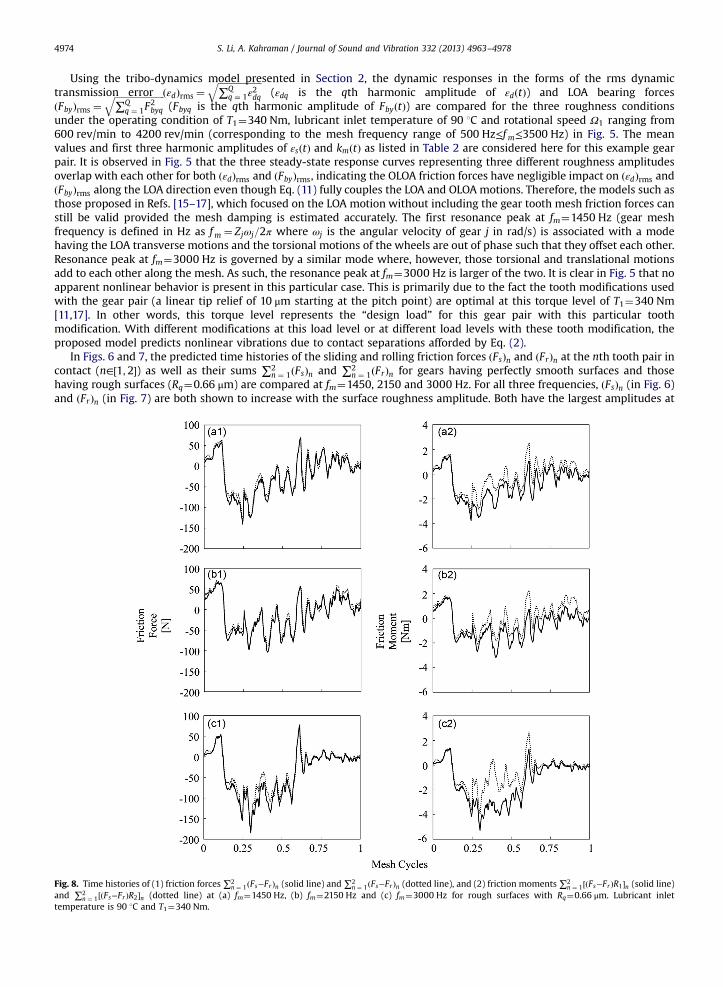
Fig. 8. Time histories of (1) friction forces ∑2n ¼ 1ðFs−FrÞn (solid line) and ∑2
n ¼ 1ðFs−FrÞn (dotted line), and (2) friction moments∑2n ¼ 1½ðFs−FrÞR1�n (solid line)
and ∑2n ¼ 1½ðFs−FrÞR2�n (dotted line) at (a) fm¼1450 Hz, (b) fm¼2150 Hz and (c) fm¼3000 Hz for rough surfaces with Rq¼0.66 μm. Lubricant inlet
temperature is 90 1C and T1¼340 Nm.
S. Li, A. Kahraman / Journal of Sound and Vibration 332 (2013) 4963–4978 4975
fm¼3000 Hz owing to the elevated dynamic tooth forces associated with Fig. 5. At the off-resonance frequency offm¼2150 Hz between the two large resonance peaks, ðFsÞn and ðFrÞn have reduced amplitudes due to the lessened dynamicresponse. In Fig. 6, ðFsÞ1 and ðFsÞ2 are seen to cancel each other since they apply in opposite directions along OLOA, while thepressure gradient induced rolling friction forces ðFrÞ1 and ðFrÞ2 add to each other as shown in Fig. 7. The magnitudes of ðFrÞnare much smaller than those of ðFsÞn for the gear pair considered. It should be noted, however, the rolling friction can becomparable to the sliding component for certain gear designs such as the one used in Ref. [30] and should be included in thefriction excitation formulations.
The total friction force time histories ∑2n ¼ 1ðFs∓FrÞn and friction moment time histories ∑2
n ¼ 1½ðFs−FrÞR1�n and∑2
n ¼ 1½ðFs þ FrÞR2�n (all appear as the friction induced terms in the equations of motion (11)) for the rough surface conditionof Rq¼0.66 μm are shown in Fig. 8. These friction forces and moments for the pinion and gear are seen to be different due tothe rolling friction component. The previous studies on friction induced gear dynamics [22–27] only consider the slidingfriction by adopting a user-defined sliding friction coefficient while ignoring the rolling component.
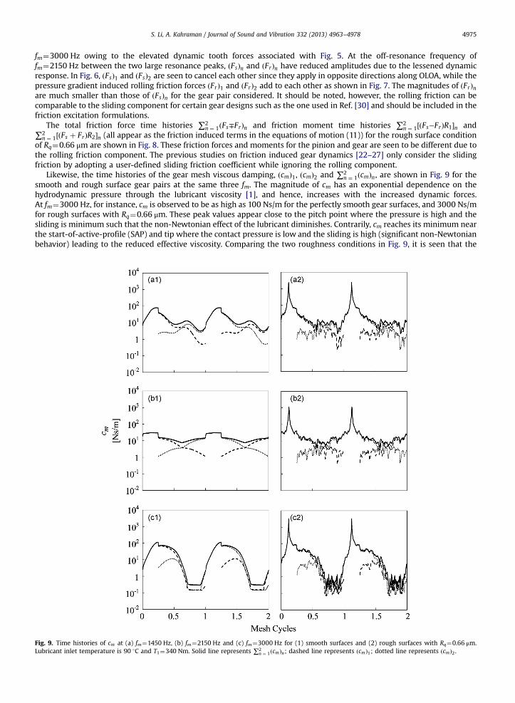
Likewise, the time histories of the gear mesh viscous damping, ðcmÞ1, ðcmÞ2 and ∑2n ¼ 1ðcmÞn, are shown in Fig. 9 for the
smooth and rough surface gear pairs at the same three fm. The magnitude of cm has an exponential dependence on thehydrodynamic pressure through the lubricant viscosity [1], and hence, increases with the increased dynamic forces.At fm¼3000 Hz, for instance, cm is observed to be as high as 100 Ns/m for the perfectly smooth gear surfaces, and 3000 Ns/mfor rough surfaces with Rq¼0.66 μm. These peak values appear close to the pitch point where the pressure is high and thesliding is minimum such that the non-Newtonian effect of the lubricant diminishes. Contrarily, cm reaches its minimum nearthe start-of-active-profile (SAP) and tip where the contact pressure is low and the sliding is high (significant non-Newtonianbehavior) leading to the reduced effective viscosity. Comparing the two roughness conditions in Fig. 9, it is seen that the
Fig. 9. Time histories of cm at (a) fm¼1450 Hz, (b) fm¼2150 Hz and (c) fm¼3000 Hz for (1) smooth surfaces and (2) rough surfaces with Rq¼0.66 μm.Lubricant inlet temperature is 90 1C and T1¼340 Nm. Solid line represents ∑2
n ¼ 1ðcmÞn; dashed line represents ðcmÞ1; dotted line represents ðcmÞ2.
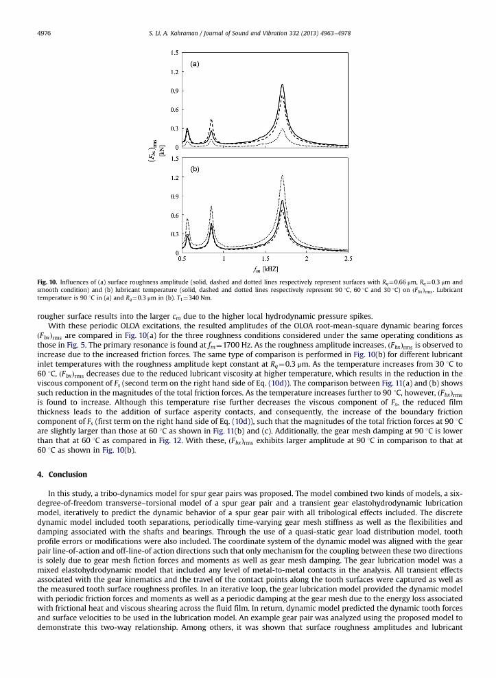
Fig. 10. Influences of (a) surface roughness amplitude (solid, dashed and dotted lines respectively represent surfaces with Rq¼0.66 μm, Rq¼0.3 μm andsmooth condition) and (b) lubricant temperature (solid, dashed and dotted lines respectively represent 90 1C, 60 1C and 30 1C) on ðFbxÞrms. Lubricanttemperature is 90 1C in (a) and Rq¼0.3 μm in (b). T1¼340 Nm.
S. Li, A. Kahraman / Journal of Sound and Vibration 332 (2013) 4963–49784976
rougher surface results into the larger cm due to the higher local hydrodynamic pressure spikes.With these periodic OLOA excitations, the resulted amplitudes of the OLOA root-mean-square dynamic bearing forces
ðFbxÞrms are compared in Fig. 10(a) for the three roughness conditions considered under the same operating conditions asthose in Fig. 5. The primary resonance is found at fm¼1700 Hz. As the roughness amplitude increases, ðFbxÞrms is observed toincrease due to the increased friction forces. The same type of comparison is performed in Fig. 10(b) for different lubricantinlet temperatures with the roughness amplitude kept constant at Rq¼0.3 μm. As the temperature increases from 30 1C to60 1C, ðFbxÞrms decreases due to the reduced lubricant viscosity at higher temperature, which results in the reduction in theviscous component of Fs (second term on the right hand side of Eq. (10d)). The comparison between Fig. 11(a) and (b) showssuch reduction in the magnitudes of the total friction forces. As the temperature increases further to 90 1C, however, ðFbxÞrmsis found to increase. Although this temperature rise further decreases the viscous component of Fs, the reduced filmthickness leads to the addition of surface asperity contacts, and consequently, the increase of the boundary frictioncomponent of Fs (first term on the right hand side of Eq. (10d)), such that the magnitudes of the total friction forces at 90 1Care slightly larger than those at 60 1C as shown in Fig. 11(b) and (c). Additionally, the gear mesh damping at 90 1C is lowerthan that at 60 1C as compared in Fig. 12. With these, ðFbxÞrms exhibits larger amplitude at 90 1C in comparison to that at60 1C as shown in Fig. 10(b).
4. Conclusion
In this study, a tribo-dynamics model for spur gear pairs was proposed. The model combined two kinds of models, a six-degree-of-freedom transverse–torsional model of a spur gear pair and a transient gear elastohydrodynamic lubricationmodel, iteratively to predict the dynamic behavior of a spur gear pair with all tribological effects included. The discretedynamic model included tooth separations, periodically time-varying gear mesh stiffness as well as the flexibilities anddamping associated with the shafts and bearings. Through the use of a quasi-static gear load distribution model, toothprofile errors or modifications were also included. The coordinate system of the dynamic model was aligned with the gearpair line-of-action and off-line-of action directions such that only mechanism for the coupling between these two directionsis solely due to gear mesh fiction forces and moments as well as gear mesh damping. The gear lubrication model was amixed elastohydrodynamic model that included any level of metal-to-metal contacts in the analysis. All transient effectsassociated with the gear kinematics and the travel of the contact points along the tooth surfaces were captured as well asthe measured tooth surface roughness profiles. In an iterative loop, the gear lubrication model provided the dynamic modelwith periodic friction forces and moments as well as a periodic damping at the gear mesh due to the energy loss associatedwith frictional heat and viscous shearing across the fluid film. In return, dynamic model predicted the dynamic tooth forcesand surface velocities to be used in the lubrication model. An example gear pair was analyzed using the proposed model todemonstrate this two-way relationship. Among others, it was shown that surface roughness amplitudes and lubricant
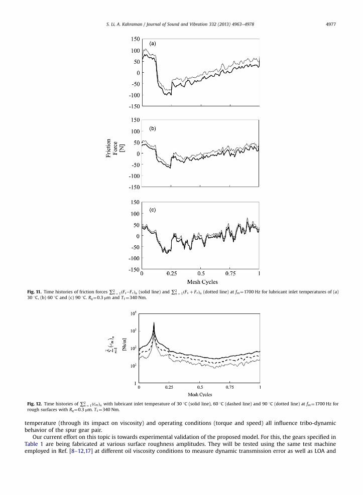
Fig. 11. Time histories of friction forces ∑2n ¼ 1ðFs−FrÞn (solid line) and ∑2
n ¼ 1ðFs þ FrÞn (dotted line) at fm¼1700 Hz for lubricant inlet temperatures of (a)30 1C, (b) 60 1C and (c) 90 1C. Rq¼0.3 μm and T1¼340 Nm.
Fig. 12. Time histories of ∑2n ¼ 1ðcmÞn with lubricant inlet temperature of 30 1C (solid line), 60 1C (dashed line) and 90 1C (dotted line) at fm¼1700 Hz for
rough surfaces with Rq¼0.3 μm. T1¼340 Nm.
S. Li, A. Kahraman / Journal of Sound and Vibration 332 (2013) 4963–4978 4977
temperature (through its impact on viscosity) and operating conditions (torque and speed) all influence tribo-dynamicbehavior of the spur gear pair.
Our current effort on this topic is towards experimental validation of the proposed model. For this, the gears specified inTable 1 are being fabricated at various surface roughness amplitudes. They will be tested using the same test machineemployed in Ref. [8–12,17] at different oil viscosity conditions to measure dynamic transmission error as well as LOA and
S. Li, A. Kahraman / Journal of Sound and Vibration 332 (2013) 4963–49784978
OLOA gear vibrations according to the method proposed by Kang and Kahraman [13]. Results of this study includingcomparisons to predictions of this model will be presented in a separate paper.
References
[1] S. Li, A. Kahraman, A spur gear mesh interface damping model based on elastohydrodynamic contact behavior, International Journal of Powertrains1 (2011) 4–21.
[2] S. Li, A. Kahraman, Influence of dynamic behavior on elastohydrodynamic lubrication of spur gears, Journal of Engineering Tribology 225 (2011)740–753.
[3] H.N. Ozguven, D.R. Houser, Mathematical models used in gear dynamics—a review, Journal of Sound and Vibration 121 (1988) 383–411.[4] J. Wang, R. Li, X. Peng, Survey of nonlinear vibration of gear transmission systems, Applied Mechanics Reviews 56 (2003) 309–329.[5] R.W. Gregor, S.L. Harris, R.G. Munro, Dynamic behavior of spur gears, Proceedings of the Institution of Mechanical Engineers 178 (1964) 207–226.[6] A. Kubo, K. Yamada, T. Aida, S. Sato, Research on ultra high speed gear devices, Transactions of Japanese Society of Mechanical Engineers 38 (1972)
2692–2715.[7] K. Umezawa, T. Ajima, H. Houjoh, Vibration of three axis gear system, Bulletin of JSME 29 (1986) 950–957.[8] G.W. Blankenship, A. Kahraman, Steady state forced response of a mechanical oscillator with combined parametric excitation and clearance type
nonlinearity, Journal of Sound and Vibration 185 (1995) 743–765.[9] A. Kahraman, G.W. Blankenship, Interactions between commensurate parametric and forcing excitations in a system with clearance, Journal of Sound
and Vibration 194 (1996) 317–336.[10] A. Kahraman, G.W. Blankenship, Experiments on nonlinear dynamic behavior of an oscillator with clearance and time-varying parameters, Journal of
Applied Mechanics 64 (1997) 217–226.[11] A. Kahraman, G.W. Blankenship, Effect of involute tip relief on dynamic response of spur gear pairs, Journal of Mechanical Design 121 (1999) 313–315.[12] A. Kahraman, G.W. Blankenship, Effect of involute contact ratio on spur gear dynamics, Journal of Mechanical Design 121 (1999) 112–118.[13] M. Kang, A. Kahraman, Measurement of vibratory motions of gears supported by compliant shafts, Mechanical Systems and Signal Processing 29 (2012)
391–403.[14] A. Kahraman, R. Singh, Non-linear dynamics of a spur gear pair, Journal of Sound and Vibration 142 (1990) 49–75.[15] H.N. Ozguven, D.R. Houser, Dynamic analysis of high speed gears by using loaded static transmission error, Journal of Sound and Vibration 125 (1988)
71–83.[16] S. Theodossiades, S. Natsiavas, Non-linear dynamics of gear pair systems with periodic stiffness and backlash, Journal of Sound and Vibration 229
(2000) 287–310.[17] V.K. Tamminana, A. Kahraman, S. Vijayakar, A study of the relationship between the dynamic factors and the dynamic transmission error of spur gear
pairs, Journal of Mechanical Design 129 (2007) 75–84.[18] T.F. Conry, A. Seireg, A mathematical programming technique for the evaluation of load distribution and optimal modifications for gear systems,
Journal of Engineering for Industry 95 (1973) 1115–1122.[19] Load Distribution Program (LDP), The Ohio State University, 2012.[20] Q. Ma, A. Kahraman, The forced dynamic response of a mechanical oscillator with periodically time-varying, piecewise non-linear stiffness, Journal of
Sound and Vibration 284 (2005) 893–914.[21] Q. Ma, A. Kahraman, Subharmonic motions of a mechanical oscillator with periodically time-varying, piecewise non-linear stiffness, Journal of Sound
and Vibration 294 (2006) 924–936.[22] M. Vaishya, R. Singh, Analysis of periodically varying gear mesh systems with Coulomb friction using Floquet theory, Journal of Sound and Vibration
243 (2001) 525–545.[23] M. Vaishya, R. Singh, Sliding friction-induced non-linearity and parametric effects in gear dynamics, Journal of Sound and Vibration 248 (2001)
671–694.[24] O. Lundvall, N. Stromberg, A. Klarbring, A flexible multi-body approach for frictional contact in spur gears, Journal of Sound and Vibration 278 (2004)
479–499.[25] P. Velex, V. Cahouet, Experimental and numerical investigations on the influence of tooth friction in spur and helical gear dynamics, Journal of
Mechanical Design 122 (2000) 515–522.[26] A. Kahraman, J. Lim, H. Ding, A dynamic model of a spur gear pair with friction. Proceedings of the 12th IFToMM World Congress, Besancon, France, June
2007.[27] S. He, R. Gunda, R. Singh, Effect of sliding friction on the dynamics of spur gear pair with realistic time-varying stiffness, Journal of Sound and Vibration
301 (2007) 927–949.[28] H. Xu, A. Kahraman, N.E. Anderson, D. Maddock, Prediction of mechanical efficiency of parallel-axis gear pairs, Journal of Mechanical Design 129 (2007)
58–68.[29] S. Li, A. Vaidyanathan, J. Harianto, A. Kahraman, Influence of design parameters on mechanical power losses of helical gear pairs, JSME Journal of
Advanced Mechanical Design, Systems, and Manufacturing 3 (2009) 146–158.[30] S. Li, A. Kahraman, Prediction of spur gear mechanical power losses using a transient elastohydrodynamic lubrication model, Tribology Transactions 53
(2010) 554–563.[31] S. Li, A. Kahraman, A method to derive friction and rolling power loss formulae for mixed elastohydrodynamic lubrication, JSME Journal of advanced
Mechanical Design, Systems, and Manufacturing 5 (2011) 252–263.[32] S. Li, A. Kahraman, M. Klein, A fatigue model for spur gear contacts operating under mixed elastohydrodynamic lubrication conditions, ASME Journal of
Mechanical Design 134 (041007) (2012) 11.[33] S. Li, A. Kahraman, A transient mixed elastohydrodynamic lubrication model for spur gear pairs, Journal of Tribology 132 (2010) 011501. (9 pp.).[34] T.A. Harris, M.N. Kotzalas, Essential Concepts of Bearing Technology, 5th ed. Taylor & Francis Group, 2007.[35] S. Li, A. Kahraman, N. Anderson, L.D. Wedeven, A model to predict scuffing failures of a ball-on-disk contact, Tribology International 60 (2013) 233–245.