Job No. Sheet No. Rev. CONSULTING Engineering … · Note that the pressure coefficient, C p is the...
54
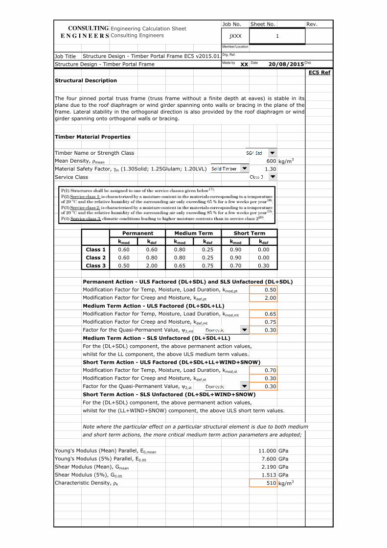
Job No. Sheet No. Rev. Job Title XX EC5 Ref Structural Description Timber Material Properties Timber Name or Strength Class Mean Density, ρ mean 600 kg/m 3 Material Safety Factor, γ m (1.30Solid; 1.25Glulam; 1.20LVL) 1.30 Service Class k mod k def k mod k def k mod k def Class 1 0.60 0.60 0.80 0.25 0.90 0.00 Class 2 0.60 0.80 0.80 0.25 0.90 0.00 Class 3 0.50 2.00 0.65 0.75 0.70 0.30 Permanent Action - ULS Factored (DL+SDL) and SLS Unfactored (DL+SDL) Modification Factor for Temp, Moisture, Load Duration, k mod,pt 0.50 Modification Factor for Creep and Moisture, k def,pt 2.00 Medium Term Action - ULS Factored (DL+SDL+LL) Modification Factor for Temp, Moisture, Load Duration, k mod,mt 0.65 Modification Factor for Creep and Moisture, k def,mt 0.75 Factor for the Quasi-Permanent Value, ψ 2,mt 0.30 Medium Term Action - SLS Unfactored (DL+SDL+LL) For the (DL+SDL) component, the above permanent action values, whilst for the LL component, the above ULS medium term values. Short Term Action - ULS Factored (DL+SDL+LL+WIND+SNOW) Modification Factor for Temp, Moisture, Load Duration, k mod,st 0.70 Modification Factor for Creep and Moisture, k def,st 0.30 Factor for the Quasi-Permanent Value, ψ 2,st 0.30 Short Term Action - SLS Unfactored (DL+SDL+WIND+SNOW) For the (DL+SDL) component, the above permanent action values, whilst for the (LL+WIND+SNOW) component, the above ULS short term values. Note where the particular effect on a particular structural element is due to both medium and short term actions, the more critical medium term action parameters are adopted; Young's Modulus (Mean) Parallel, E 0,mean 11.000 GPa Young's Modulus (5%) Parallel, E 0.05 7.600 GPa Shear Modulus (Mean), G mean 2.190 GPa Shear Modulus (5%), G 0.05 1.513 GPa Characteristic Density, ρ k 510 kg/m 3 CONSULTING E N G I N E E R S Engineering Calculation Sheet Consulting Engineers jXXX 1 Structure Design - Timber Portal Frame EC5 v2015.01. Structure Design - Timber Portal Frame 20/08/2015 The four pinned portal truss frame (truss frame without a finite depth at eaves) is stable in its plane due to the roof diaphragm or wind girder spanning onto walls or bracing in the plane of the frame. Lateral stability in the orthogonal direction is also provided by the roof diaphragm or wind girder spanning onto orthogonal walls or bracing. Permanent Short Term Medium Term Made by Date Chd. Drg. Ref. Member/Location
Transcript of Job No. Sheet No. Rev. CONSULTING Engineering … · Note that the pressure coefficient, C p is the...
Job No. Sheet No. Rev.
Job Title
XX
EC5 Ref
Structural Description
Timber Material Properties
Timber Name or Strength Class
Mean Density, ρmean 600 kg/m3
Material Safety Factor, γm (1.30Solid; 1.25Glulam; 1.20LVL) 1.30
Service Class
kmod kdef kmod kdef kmod kdef
Class 1 0.60 0.60 0.80 0.25 0.90 0.00
Class 2 0.60 0.80 0.80 0.25 0.90 0.00
Class 3 0.50 2.00 0.65 0.75 0.70 0.30
Permanent Action - ULS Factored (DL+SDL) and SLS Unfactored (DL+SDL)
Modification Factor for Temp, Moisture, Load Duration, kmod,pt 0.50
Modification Factor for Creep and Moisture, kdef,pt 2.00
Medium Term Action - ULS Factored (DL+SDL+LL)
Modification Factor for Temp, Moisture, Load Duration, kmod,mt 0.65
Modification Factor for Creep and Moisture, kdef,mt 0.75
Factor for the Quasi-Permanent Value, ψ2,mt 0.30
Medium Term Action - SLS Unfactored (DL+SDL+LL)
For the (DL+SDL) component, the above permanent action values,
whilst for the LL component, the above ULS medium term values.
Short Term Action - ULS Factored (DL+SDL+LL+WIND+SNOW)
Modification Factor for Temp, Moisture, Load Duration, kmod,st 0.70
Modification Factor for Creep and Moisture, kdef,st 0.30
Factor for the Quasi-Permanent Value, ψ2,st 0.30
Short Term Action - SLS Unfactored (DL+SDL+WIND+SNOW)
For the (DL+SDL) component, the above permanent action values,
whilst for the (LL+WIND+SNOW) component, the above ULS short term values.
Note where the particular effect on a particular structural element is due to both medium
and short term actions, the more critical medium term action parameters are adopted;
Young's Modulus (Mean) Parallel, E0,mean 11.000 GPa
Young's Modulus (5%) Parallel, E0.05 7.600 GPa
Shear Modulus (Mean), Gmean 2.190 GPa
Shear Modulus (5%), G0.05 1.513 GPa
Characteristic Density, ρk 510 kg/m3
CONSULTING
E N G I N E E R S
Engineering Calculation Sheet Consulting Engineers jXXX 1
Structure Design - Timber Portal Frame EC5 v2015.01.xlsm
Structure Design - Timber Portal Frame 20/08/2015
The four pinned portal truss frame (truss frame without a finite depth at eaves) is stable in itsplane due to the roof diaphragm or wind girder spanning onto walls or bracing in the plane of theframe. Lateral stability in the orthogonal direction is also provided by the roof diaphragm or windgirder spanning onto orthogonal walls or bracing.
Permanent Short TermMedium Term
Made by Date Chd.
Drg. Ref.
Member/Location
Job No. Sheet No. Rev.
Job Title
XX
EC5 Ref
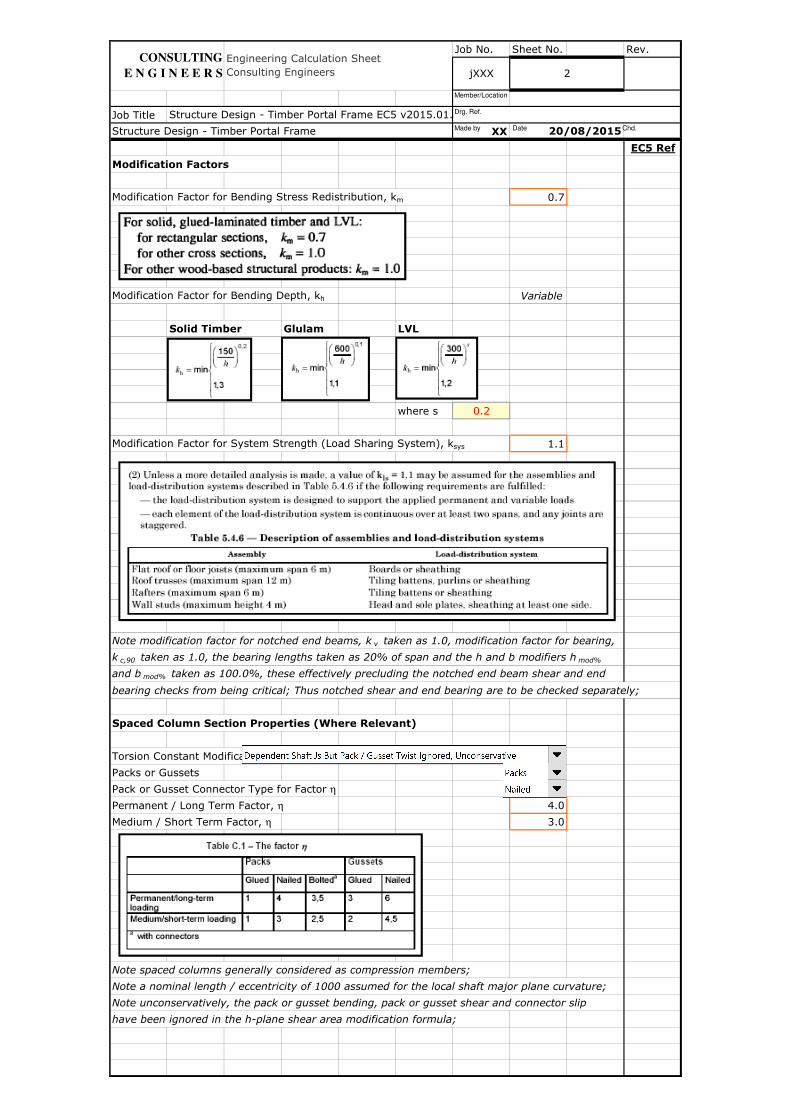
Modification Factors
Modification Factor for Bending Stress Redistribution, km 0.7
Modification Factor for Bending Depth, kh Variable
Solid Timber Glulam LVL
where s 0.2
Modification Factor for System Strength (Load Sharing System), ksys 1.1
Note modification factor for notched end beams, k v taken as 1.0, modification factor for bearing,
k c,90 taken as 1.0, the bearing lengths taken as 20% of span and the h and b modifiers h mod%
and b mod% taken as 100.0%, these effectively precluding the notched end beam shear and end
bearing checks from being critical; Thus notched shear and end bearing are to be checked separately;
Spaced Column Section Properties (Where Relevant)
Torsion Constant Modification
Packs or Gussets
Pack or Gusset Connector Type for Factor η
Permanent / Long Term Factor, η 4.0
Medium / Short Term Factor, η 3.0
Note spaced columns generally considered as compression members;
Note a nominal length / eccentricity of 1000 assumed for the local shaft major plane curvature;
Note unconservatively, the pack or gusset bending, pack or gusset shear and connector slip
have been ignored in the h-plane shear area modification formula;
CONSULTING
E N G I N E E R S jXXX 2
20/08/2015
Engineering Calculation Sheet Consulting Engineers
Structure Design - Timber Portal Frame EC5 v2015.01.xlsm
Structure Design - Timber Portal Frame Made by Date Chd.
Drg. Ref.
Member/Location
Job No. Sheet No. Rev.
Job Title
XX
EC5 Ref
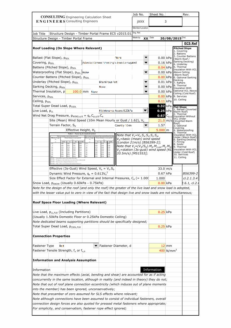
Roof Loading (On Slope Where Relevant)
Ballast (Flat Slope), pSDL 0.00 kPa
Covering, pSDL 0.16 kPa
Battens (Pitched Slope), pSDL 0.04 kPa
Waterproofing (Flat Slope), pSDL 0.00 kPa
Counter Battens (Pitched Slope), pSDL 0.00 kPa
Underlay (Pitched Slope), pSDL 0.01 kPa
Sarking Decking, pSDL 0.00 kPa
Thermal Insulation, pSDL 100.0 mm 0.00 kPa
Services, pSDL 0.00 kPa
Ceiling, pSDL 0.11 kPa
Total Super Dead Load, pΣSDL 0.32 kPa
Live Load, pLL 0.25 kPa
Wind Net Drag Pressure, pWIND,u/d = qs.Cp,u/d.Ca 0.67 Cp,u/d kPa
Site (Mean) Wind Speed (10m Mean Hourly or Gust / 1.62), Vs 21.0 m/s
Terrain Factor, Sb 1.57
Effective Height, He 5.000 m
Effective (3s-Gust) Wind Speed, Ve = Vs.Sb 33.0 m/s
Dynamic Wind Pressure, qs = 0.613Ve2 0.67 kPa BS6399-2
Size Effect Factor for External and Internal Pressures, Ca (= 1.000 Conservatively)1.000 cl.2.1.3.4
Snow Load, pSNOW (Usually 0.60kPa − 0.75kPa) 0.00 kPa cl.2.6.1, cl.2.6.2
Note for the design of the roof (and only the roof) the greater of the live load and snow load is adopted,
with the lesser value put to zero in view of the fact that design live and snow loads are not simultaneous;
Roof Space Floor Loading (Where Relevant)
Live Load, pLL,FLR (Including Partitions) 0.25 kPa
(Usually 1.50kPa Domestic Floor or 0.25kPa Domestic Ceiling)
Note dedicated beams supporting partitions should be specifically designed;
Total Super Dead Load, pΣSDL,FLR 0.25 kPa
Connection Properties
Fastener Type Fastener Diameter, d 12 mm
Fastener Tensile Strength, fu or fu,k 400 N/mm2
Information and Analysis Assumption
Information
Note that the maximum effects (axial, bending and shear) are accounted for as if acting
concurrently in the same location, although in reality (and indeed in theory) they do not;
Note that out of roof plane connection eccentricity (which induces out of plane moments
into the member) has been ignored, unconservatively;
Note that precamber of zero assumed for SLS effects where relevant;
Note although connections have been assumed to consist of individual fasteners, overall
connection design forces are also quoted for pressed metal fasteners where appropriate;
For simplicity, and conservatism, fastener rope effect ignored;
CONSULTING
E N G I N E E R S
Structure Design - Timber Portal Frame 20/08/2015
3
Structure Design - Timber Portal Frame EC5 v2015.01.xlsm
Engineering Calculation Sheet Consulting Engineers jXXX
Information
Pitched Slope1. Covering2. Battens3. Counter Battens (Warm Roof / Sarking Decking)4. Underlay5. Thermal Insulation With VCL Above Ceiling (Warm Roof)6. Optional Sarking Decking7. Rafters 8. Thermal Insulation With Optional VCL Above Ceiling (Cold Roof)9. Services
10. Ceiling
Flat Slope1. Ballast (Inverted Warm Roof)2. Thermal Insulation Without VCL Under (Inverted Warm Roof)3. Optional Covering4. Waterproofing5. Thermal Insulation With VCL Under (Warm Roof)6. Sarking Decking7. Firring 8. Joists 9. Thermal Insulation With VCL Under (Cold Roof) 10. Services 11. Ceiling
Note that Vs=Vb.Sa.Sd.Ss.Sp, Vb=basic (mean) wind speed (London 21m/s) [BS6399-2];Note that Vs=(VS/Sb).Md.Mz,cat.Ms.Mh, VS=station (3s-gust) wind speed (KL 33.5m/s) [MS1553];
Made by Date Chd.
Drg. Ref.
Member/Location
Job No. Sheet No. Rev.
Job Title
XX
EC5 Ref
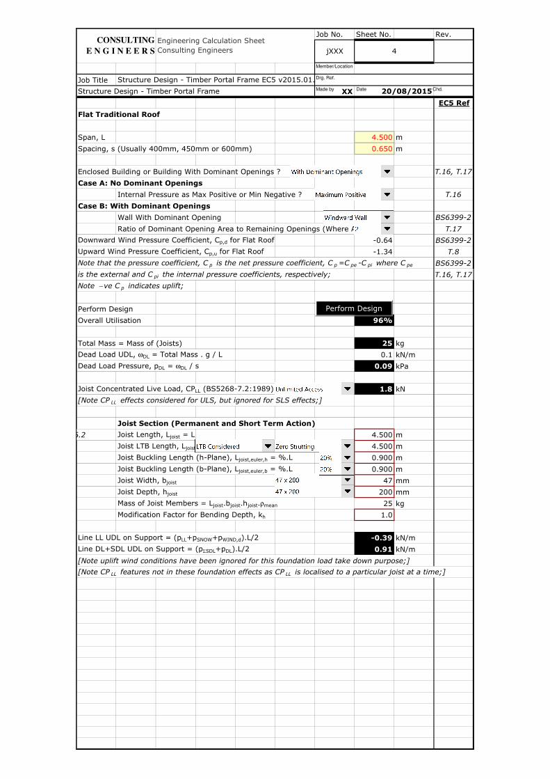
Flat Traditional Roof
Span, L 4.500 m
Spacing, s (Usually 400mm, 450mm or 600mm) 0.650 m
Enclosed Building or Building With Dominant Openings ? T.16, T.17
Case A: No Dominant Openings
Internal Pressure as Max Positive or Min Negative ? T.16
Case B: With Dominant Openings
Wall With Dominant Opening BS6399-2
Ratio of Dominant Opening Area to Remaining Openings (Where Applicable) T.17
Downward Wind Pressure Coefficient, Cp,d for Flat Roof -0.64 BS6399-2
Upward Wind Pressure Coefficient, Cp,u for Flat Roof -1.34 T.8
Note that the pressure coefficient, C p is the net pressure coefficient, C p =C pe -C pi where C pe BS6399-2
is the external and C pi the internal pressure coefficients, respectively; T.16, T.17
Note − ve C p indicates uplift;
Perform Design
Overall Utilisation 96%
Total Mass = Mass of (Joists) 25 kg
Dead Load UDL, ωDL = Total Mass . g / L 0.1 kN/m
Dead Load Pressure, pDL = ωDL / s 0.09 kPa
Joist Concentrated Live Load, CPLL (BS5268-7.2:1989) 1.8 kN
[Note CP LL effects considered for ULS, but ignored for SLS effects;]
Joist Section (Permanent and Short Term Action)
cl.2.6.1, cl.2.6.2 Joist Length, Ljoist = L 4.500 m
Joist LTB Length, Ljoist,LTB = L / (1 + Struttings) 4.500 m
Joist Buckling Length (h-Plane), Ljoist,euler,h = %.L 0.900 m
Joist Buckling Length (b-Plane), Ljoist,euler,b = %.L 0.900 m
Joist Width, bjoist 47 mm
Joist Depth, hjoist 200 mm
Mass of Joist Members = Ljoist.bjoist.hjoist.ρmean 25 kg
Modification Factor for Bending Depth, kh 1.0
Line LL UDL on Support = (pLL+pSNOW+pWIND,d).L/2 -0.39 kN/m
Line DL+SDL UDL on Support = (pΣSDL+pDL).L/2 0.91 kN/m
[Note uplift wind conditions have been ignored for this foundation load take down purpose;]
[Note CP LL features not in these foundation effects as CP LL is localised to a particular joist at a time;]
Engineering Calculation Sheet Consulting Engineers jXXX 4
Structure Design - Timber Portal Frame EC5 v2015.01.xlsm
Structure Design - Timber Portal Frame 20/08/2015
CONSULTING
E N G I N E E R S
Perform Design
Made by Date Chd.
Drg. Ref.
Member/Location
Job No. Sheet No. Rev.
Job Title
XX
EC5 Ref
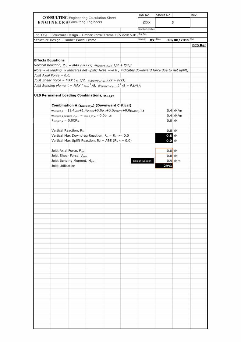
Effects Equations
Vertical Reaction, R V = MAX ( ω .L/2, ω BEREFT of pLL .L/2 + P/2);
Note − ve loading ω indicates net uplift; Note − ve R v indicates downward force due to net uplift;
Joist Axial Force = 0.0;
Joist Shear Force = MAX ( ω .L/2, ω BEREFT of pLL .L/2 + P/2);
Joist Bending Moment = MAX ( ω .L 2 /8, ω BEREFT of pLL .L 2 /8 + P.L/4);
ULS Permanent Loading Combinations, ωωωωULS,PT
Combination A (ωωωωULS,PT,A) (Downward Critical)
ωULS,PT,A = [1.4pDL+1.4pΣSDL+0.0pLL+0.0pSNOW+0.0pWIND,d].s 0.4 kN/m
ωULS,PT,A,BEREFT of pLL = ωULS,PT,A − 0.0pLL.s 0.4 kN/m
PULS,PT,A = 0.0CPLL 0.0 kN
Vertical Reaction, RV 0.8 kN
Vertical Max Downdrag Reaction, RV = RV >= 0.0 0.8 kN
Vertical Max Uplift Reaction, RV = ABS (RV <= 0.0) 0.0 kN
Joist Axial Force, Fjoist 0.0 kN
Joist Shear Force, Vjoist 0.8 kN
Joist Bending Moment, Mjoist 0.9 kNm
Joist Utilisation 29%
5
Engineering Calculation Sheet Consulting Engineers jXXX
Structure Design - Timber Portal Frame EC5 v2015.01.xlsm
Structure Design - Timber Portal Frame 20/08/2015
CONSULTING
E N G I N E E R S
Design Section
Made by Date Chd.
Drg. Ref.
Member/Location
Job No. Sheet No. Rev.
Job Title
XX
EC5 Ref
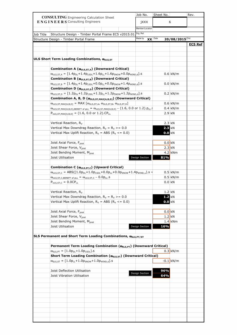
ULS Short Term Loading Combinations, ωωωωULS,ST
Combination A (ωωωωULS,ST,A) (Downward Critical)
ωULS,ST,A = [1.4pDL+1.4pΣSDL+1.6pLL+1.6pSNOW+0.0pWIND,d].s 0.6 kN/m
Combination B (ωωωωULS,ST,B) (Downward Critical)
ωULS,ST,B = [1.4pDL+1.4pΣSDL+0.0pLL+0.0pSNOW+1.4pWIND,d].s 0.0 kN/m
Combination D (ωωωωULS,ST,D) (Downward Critical)
ωULS,ST,D = [1.2pDL+1.2pΣSDL+1.2pLL+1.2pSNOW+1.2pWIND,d].s 0.2 kN/m
Combination A, B, D (ωωωωULS,ST,MAX[A,B,D]) (Downward Critical)
ωULS,ST,MAX[A,B,D] = MAX [ωULS,ST,A, ωULS,ST,B, ωULS,ST,D] 0.6 kN/m
ωULS,ST,MAX[A,B,D],BEREFT of pLL = ωULS,ST,MAX[A,B,D] − (1.6, 0.0 or 1.2).pLL.s 0.4 kN/m
PULS,ST,MAX[A,B,D] = (1.6, 0.0 or 1.2).CPLL 2.9 kN
Vertical Reaction, RV 2.3 kN
Vertical Max Downdrag Reaction, RV = RV >= 0.0 2.3 kN
Vertical Max Uplift Reaction, RV = ABS (RV <= 0.0) 0.0 kN
Joist Axial Force, Fjoist 0.0 kN
Joist Shear Force, Vjoist 2.3 kN
Joist Bending Moment, Mjoist 4.2 kNm
Joist Utilisation 81%
Combination C (ωωωωULS,ST,C) (Upward Critical)
ωULS,ST,C = ABS([1.0pDL+1.0pΣSDL+0.0pLL+0.0pSNOW+1.4pWIND,u].s <= 0.0) 0.5 kN/m
ωULS,ST,C,BEREFT of pLL = ωULS,ST,C − 0.0pLL.s 0.5 kN/m
PULS,ST,C = 0.0CPLL 0.0 kN
Vertical Reaction, RV 1.2 kN
Vertical Max Downdrag Reaction, RV = RV >= 0.0 1.2 kN
Vertical Max Uplift Reaction, RV = ABS (RV <= 0.0) 0.0 kN
Joist Axial Force, Fjoist 0.0 kN
Joist Shear Force, Vjoist 1.2 kN
Joist Bending Moment, Mjoist 1.4 kNm
Joist Utilisation 16%
SLS Permanent and Short Term Loading Combinations, ωωωωSLS,PT/ST
Permanent Term Loading Combination (ωωωωSLS,PT) (Downward Critical)
ωSLS,PT = [1.0pDL+1.0pΣSDL].s 0.3 kN/m
Short Term Loading Combination (ωωωωSLS,ST) (Downward Critical)
ωSLS,ST = [1.0pLL+1.0pSNOW+1.0pWIND,d].s -0.1 kN/m
Joist Deflection Utilisation 96%
Joist Vibration Utilisation 64%
Structure Design - Timber Portal Frame
Engineering Calculation Sheet Consulting Engineers jXXX 6
20/08/2015
Structure Design - Timber Portal Frame EC5 v2015.01.xlsm
CONSULTING
E N G I N E E R S
Design Section
Design Section
Design Section
Made by Date Chd.
Drg. Ref.
Member/Location

Job No. Sheet No. Rev.
Job Title
XX
EC5 Ref
Lean to Traditional Roof
Span, L 5.000 m
Depth, H 4.000 m
Span L / Depth H 1.3
Spacing, s (Usually 400mm, 450mm or 600mm) 0.400 m
Length of Slope, q = √(L2 + H2) 6.403 m
Enclosed Building or Building With Dominant Openings ? T.16, T.17
Case A: No Dominant Openings
Internal Pressure as Max Positive or Min Negative ? T.16
Case B: With Dominant Openings
Wall With Dominant Opening BS6399-2
Ratio of Dominant Opening Area to Remaining Openings (Where Applicable) T.17
α BS6399-2
(degrees) Cp,d Cp,u Cp,d Cp,u T.9
5 -0.64 -1.24 -1.44 -1.44 BS6399-2
15 -0.44 -1.04 -1.54 -1.54 T.16, T.17
30 -0.24 -0.84 -1.54 -1.54
45 0.06 -0.64 -1.54 -1.54
60 0.16 0.16 -1.34 -1.34
75 0.16 0.16 -1.34 -1.34
Note that the pressure coefficient, C p is the net pressure coefficient, C p =C pe -C pi
where C pe is the external and C pi the internal pressure coefficients, respectively;
Note − ve C p indicates uplift;
Pitch Angle, α = arctan (H/L) 38.7 degrees
Windward Downward Wind Pressure Coefficient, Cp,d,windward -0.06
Windward Upward Wind Pressure Coefficient, Cp,u,windward -0.72
Leeward Downward Wind Pressure Coefficient, Cp,d,leeward -1.54
Leeward Upward Wind Pressure Coefficient, Cp,u,leeward -1.54
jXXX
Structure Design - Timber Portal Frame EC5 v2015.01.xlsm
Structure Design - Timber Portal Frame 20/08/2015
Windward Leeward
7
CONSULTING
E N G I N E E R S
Engineering Calculation Sheet Consulting Engineers
Made by Date Chd.
Drg. Ref.
Member/Location
Job No. Sheet No. Rev.
Job Title
XX
EC5 Ref
Perform Design
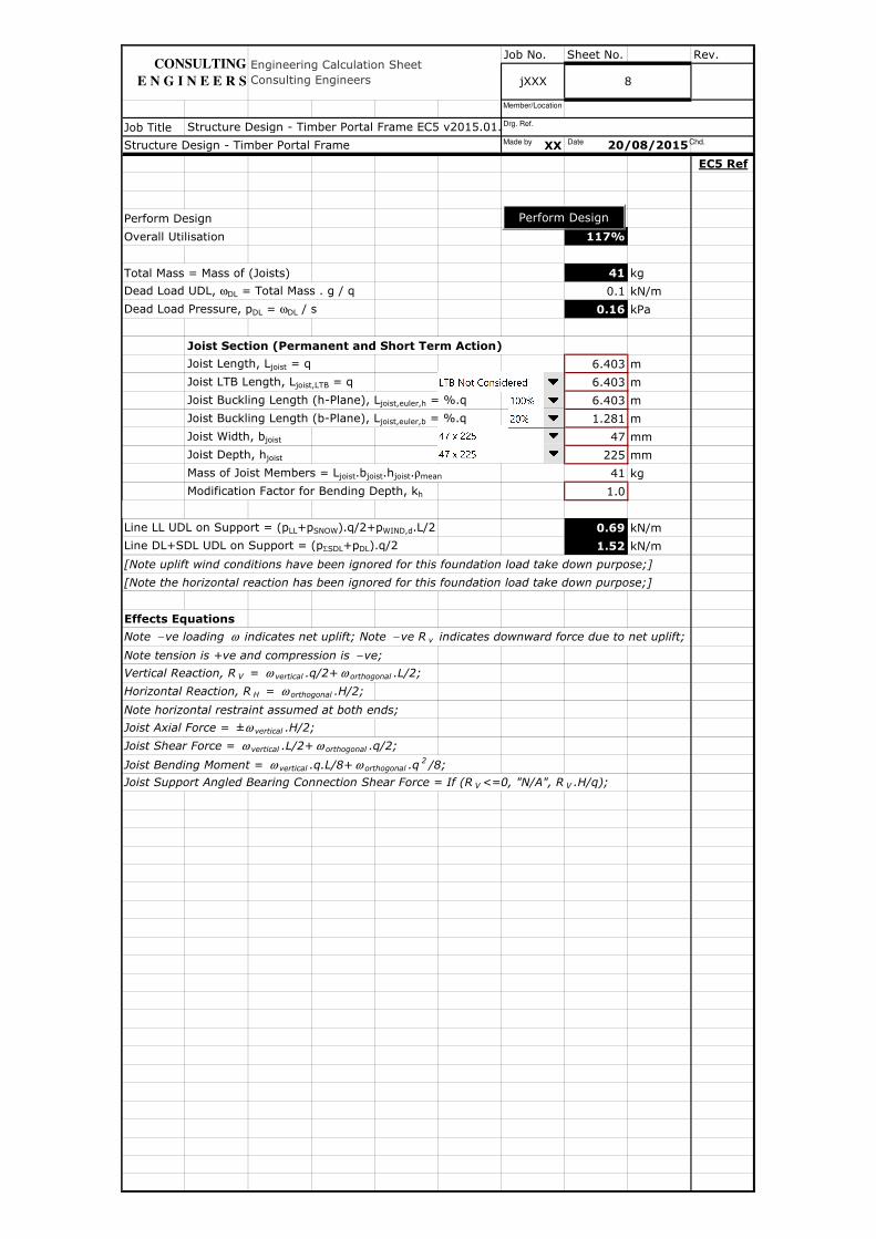
Overall Utilisation 117%
Total Mass = Mass of (Joists) 41 kg
Dead Load UDL, ωDL = Total Mass . g / q 0.1 kN/m
Dead Load Pressure, pDL = ωDL / s 0.16 kPa
Joist Section (Permanent and Short Term Action)
Joist Length, Ljoist = q 6.403 m
Joist LTB Length, Ljoist,LTB = q 6.403 m
Joist Buckling Length (h-Plane), Ljoist,euler,h = %.q 6.403 m
Joist Buckling Length (b-Plane), Ljoist,euler,b = %.q 1.281 m
Joist Width, bjoist 47 mm
Joist Depth, hjoist 225 mm
Mass of Joist Members = Ljoist.bjoist.hjoist.ρmean 41 kg
Modification Factor for Bending Depth, kh 1.0
Line LL UDL on Support = (pLL+pSNOW).q/2+pWIND,d.L/2 0.69 kN/m
Line DL+SDL UDL on Support = (pΣSDL+pDL).q/2 1.52 kN/m
[Note uplift wind conditions have been ignored for this foundation load take down purpose;]
[Note the horizontal reaction has been ignored for this foundation load take down purpose;]
Effects Equations
Note − ve loading ω indicates net uplift; Note − ve R v indicates downward force due to net uplift;
Note tension is +ve and compression is − ve;
Vertical Reaction, R V = ω vertical .q/2+ ω orthogonal .L/2;
Horizontal Reaction, R H = ω orthogonal .H/2;
Note horizontal restraint assumed at both ends;
Joist Axial Force = ±ω vertical .H/2;
Joist Shear Force = ω vertical .L/2+ ω orthogonal .q/2;
Joist Bending Moment = ω vertical .q.L/8+ ω orthogonal .q2 /8;
Joist Support Angled Bearing Connection Shear Force = If (R V <=0, "N/A", R V .H/q);
Structure Design - Timber Portal Frame 20/08/2015
Structure Design - Timber Portal Frame EC5 v2015.01.xlsm
Engineering Calculation Sheet Consulting Engineers jXXX 8
CONSULTING
E N G I N E E R S
Perform Design
Made by Date Chd.
Drg. Ref.
Member/Location
Job No. Sheet No. Rev.
Job Title
XX
EC5 Ref
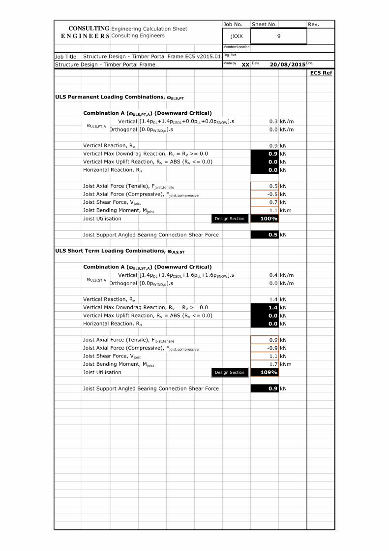
ULS Permanent Loading Combinations, ωωωωULS,PT
Combination A (ωωωωULS,PT,A) (Downward Critical)
Vertical [1.4pDL+1.4pΣSDL+0.0pLL+0.0pSNOW].s 0.3 kN/m
Orthogonal [0.0pWIND,d].s 0.0 kN/m
Vertical Reaction, RV 0.9 kN
Vertical Max Downdrag Reaction, RV = RV >= 0.0 0.9 kN
Vertical Max Uplift Reaction, RV = ABS (RV <= 0.0) 0.0 kN
Horizontal Reaction, RH 0.0 kN
Joist Axial Force (Tensile), Fjoist,tensile 0.5 kN
Joist Axial Force (Compressive), Fjoist,compressive -0.5 kN
Joist Shear Force, Vjoist 0.7 kN
Joist Bending Moment, Mjoist 1.1 kNm
Joist Utilisation 100%
Joist Support Angled Bearing Connection Shear Force 0.5 kN
ULS Short Term Loading Combinations, ωωωωULS,ST
Combination A (ωωωωULS,ST,A) (Downward Critical)
Vertical [1.4pDL+1.4pΣSDL+1.6pLL+1.6pSNOW].s 0.4 kN/m
Orthogonal [0.0pWIND,d].s 0.0 kN/m
Vertical Reaction, RV 1.4 kN
Vertical Max Downdrag Reaction, RV = RV >= 0.0 1.4 kN
Vertical Max Uplift Reaction, RV = ABS (RV <= 0.0) 0.0 kN
Horizontal Reaction, RH 0.0 kN
Joist Axial Force (Tensile), Fjoist,tensile 0.9 kN
Joist Axial Force (Compressive), Fjoist,compressive -0.9 kN
Joist Shear Force, Vjoist 1.1 kN
Joist Bending Moment, Mjoist 1.7 kNm
Joist Utilisation 109%
Joist Support Angled Bearing Connection Shear Force 0.9 kN
Structure Design - Timber Portal Frame
9
20/08/2015
Engineering Calculation Sheet Consulting Engineers jXXX
Structure Design - Timber Portal Frame EC5 v2015.01.xlsm
ωULS,PT,A
ωULS,ST,A
CONSULTING
E N G I N E E R S
Design Section
Design Section
Made by Date Chd.
Drg. Ref.
Member/Location
Job No. Sheet No. Rev.
Job Title
XX
EC5 Ref
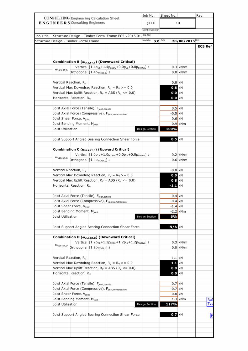
Combination B (ωωωωULS,ST,B) (Downward Critical)
Vertical [1.4pDL+1.4pΣSDL+0.0pLL+0.0pSNOW].s 0.3 kN/m
Orthogonal [1.4pWIND,d].s 0.0 kN/m
Vertical Reaction, RV 0.8 kN
Vertical Max Downdrag Reaction, RV = RV >= 0.0 0.8 kN
Vertical Max Uplift Reaction, RV = ABS (RV <= 0.0) 0.0 kN
Horizontal Reaction, RH 0.0 kN
Joist Axial Force (Tensile), Fjoist,tensile 0.5 kN
Joist Axial Force (Compressive), Fjoist,compressive -0.5 kN
Joist Shear Force, Vjoist 0.6 kN
Joist Bending Moment, Mjoist 0.9 kNm
Joist Utilisation 100%
Joist Support Angled Bearing Connection Shear Force 0.5 kN
Combination C (ωωωωULS,ST,C) (Upward Critical)
Vertical [1.0pDL+1.0pΣSDL+0.0pLL+0.0pSNOW].s 0.2 kN/m
Orthogonal [1.4pWIND,u].s -0.6 kN/m
Vertical Reaction, RV -0.8 kN
Vertical Max Downdrag Reaction, RV = RV >= 0.0 0.0 kN
Vertical Max Uplift Reaction, RV = ABS (RV <= 0.0) 0.8 kN
Horizontal Reaction, RH -1.1 kN
Joist Axial Force (Tensile), Fjoist,tensile 0.4 kN
Joist Axial Force (Compressive), Fjoist,compressive -0.4 kN
Joist Shear Force, Vjoist -1.4 kN
Joist Bending Moment, Mjoist -2.2 kNm
Joist Utilisation 6%
Joist Support Angled Bearing Connection Shear Force N/A kN
Combination D (ωωωωULS,ST,D) (Downward Critical)
Vertical [1.2pDL+1.2pΣSDL+1.2pLL+1.2pSNOW].s 0.3 kN/m
Orthogonal [1.2pWIND,d].s 0.0 kN/m
Vertical Reaction, RV 1.1 kN
Vertical Max Downdrag Reaction, RV = RV >= 0.0 1.1 kN
Vertical Max Uplift Reaction, RV = ABS (RV <= 0.0) 0.0 kN
Horizontal Reaction, RH 0.0 kN
Joist Axial Force (Tensile), Fjoist,tensile 0.7 kN
Joist Axial Force (Compressive), Fjoist,compressive -0.7 kN
Joist Shear Force, Vjoist 0.8 kN
Joist Bending Moment, Mjoist 1.3 kNm
Joist Utilisation 117%
Joist Support Angled Bearing Connection Shear Force 0.7 kN
20/08/2015Structure Design - Timber Portal Frame
ωULS,ST,D
ωULS,ST,B
ωULS,ST,C
Structure Design - Timber Portal Frame EC5 v2015.01.xlsm
Engineering Calculation Sheet Consulting Engineers jXXX 10
CONSULTING
E N G I N E E R S
Design Section
Design Section
Design Section
RaftersTypical
Purlins
Made by Date Chd.
Drg. Ref.
Member/Location
Job No. Sheet No. Rev.
Job Title
XX
EC5 Ref
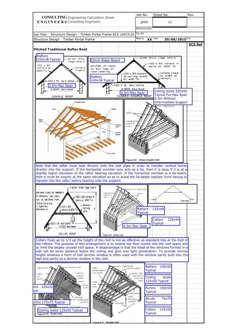
Pitched Traditional Rafter Roof
11
Structure Design - Timber Portal Frame EC5 v2015.01.xlsm
Engineering Calculation Sheet Consulting Engineers jXXX
Structure Design - Timber Portal Frame 20/08/2015
CONSULTING
E N G I N E E R S
Note that the rafter must bear directly onto the wall plate in order to transfer vertical forcesdirectly into the support. If the horizontal member only acts as a tie, then it is okay if it is at aslightly higher elevation to the rafter bearing elevation. If the horizontal member is a tie-beam,then it must be exactly at the same elevation so as to avoid the tie-beam reaction from having totransfer into the rafter before bearing onto the support.
3.5m Max Span
Rafters 100x38 Typical
5.5m Max Span
32mm Ridge Board
Rafters 100x38 Typical
Ceiling Joists 220x50 Typical For Max Span 5.5m Without Intermediate Support
Collars fixed up to 1/3 up the height of the roof is not as effective as standard ties at the foot ofthe rafters. The purpose of this arrangement is to extend top floor rooms into the roof space andso limit the largely unused roof space. A disadvantage is that the head of the windows formed in awall will be some distance below the ceiling and give less light penetration. To provide normalheight windows a form of half dormer window is often used with the window partly built into thewall and partly as a dormer window in the roof.
4.5m Max Span
Rafters 125x44Typical
Collars 125x44Typical
Rafters 125x50Typical
Purlins 175x75 Typical
Ceiling Joists 125x50 Typical
Rafters 150x50Typical
Ceiling Joists125x50 Typical
Purlins 150x50Typical
Struts 75x75Typical
Collars 125x50Typical
Made by Date Chd.
Drg. Ref.
Member/Location
Job No. Sheet No. Rev.
Job Title
XX
EC5 Ref
20/08/2015Structure Design - Timber Portal Frame
Engineering Calculation Sheet Consulting Engineers jXXX 12
Structure Design - Timber Portal Frame EC5 v2015.01.xlsm
CONSULTING
E N G I N E E R S
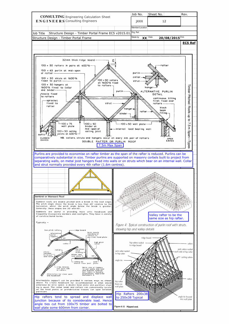
Purlins are provided to economise on rafter timber as the span of the rafter is reduced. Purlins can be comparatively substantial in size. Timber purlins are supported on masonry corbels built to project from separating walls, on metal joist hangers fixed into walls or on struts which bear on an internal wall. Collar and strut normally provided every 4th rafter (1.6m centres).
7.5m Max Span
Hip Rafters 200x38to 250x38 TypicalHip rafters tend to spread and displace wall
junction because of its considerable load. Henceangle ties cut from 100x75 timber are bolted towall plate some 600mm from corner.
Valley rafter to be the same size as hip rafter.
Made by Date Chd.
Drg. Ref.
Member/Location
Job No. Sheet No. Rev.
Job Title
XX
EC5 Ref
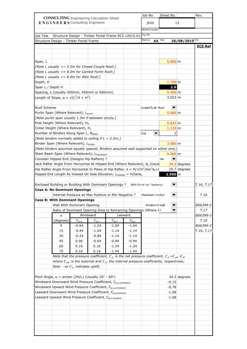
Span, L 5.000 m
[Note L usually <= 5.5m for Closed Couple Roof;]
[Note L usually <= 8.0m for Canted Purlin Roof;]
[Note L usually <= 8.0m for Attic Roof;]
Depth, H 1.700 m
Span L / Depth H 2.9
Spacing, s (Usually 400mm, 450mm or 600mm) 0.400 m
Length of Slope, q = √(L2/4 + H2) 3.023 m
Roof Scheme
Purlin Span (Where Relevant), Lpurlin 5.000 m
[Note purlin span usually 1.5m if between struts;]
Post Height (Where Relevant), H0 0.833 m
Collar Height (Where Relevant), H1 1.133 m
Number of Binders Along Span L, NBIND 1
[Note binders normally added to ceiling if L > 2.5m;]
Binder Span (Where Relevant), Lbinder 3.000 m
[Note binders assumed equally spaced; Binders assumed wall supported on either end;]
Steel Beam Span (Where Relevant), Lsteelbeam 5.000 m
Consider Hipped End (Designs Hip Rafters) ?
Jack Rafter Angle From Horizontal At Hipped End (Where Relevant), θ0 (Usually = 34.2 degrees
Hip Rafter Angle From Horizontal In Plane of Hip Rafter, θ = H/√(H2/tan2θ0+L 25.7 degrees
Hipped End Length As Viewed On Side Elevation, LHIPEND = H/tanθ0 2.500 m
Enclosed Building or Building With Dominant Openings ? T.16, T.17
Case A: No Dominant Openings
Internal Pressure as Max Positive or Min Negative ? T.16
Case B: With Dominant Openings
Wall With Dominant Opening BS6399-2
Ratio of Dominant Opening Area to Remaining Openings (Where Applicable) T.17
α BS6399-2
(degrees) Cp,d Cp,u Cp,d Cp,u T.10
5 -0.64 -1.24 -1.04 -1.04 BS6399-2
15 -0.44 -1.04 -1.14 -1.14 T.16, T.17
30 -0.24 -0.84 -1.14 -1.14
45 0.06 -0.64 -0.94 -0.94
60 0.16 0.16 -1.24 -1.24
75 0.16 0.16 -1.44 -1.44
Note that the pressure coefficient, C p is the net pressure coefficient, C p =C pe -C pi
where C pe is the external and C pi the internal pressure coefficients, respectively;
Note − ve C p indicates uplift;
Pitch Angle, α = arctan (2H/L) (Usually 20° − 60°) 34.2 degrees
Windward Downward Wind Pressure Coefficient, Cp,d,windward -0.15
Windward Upward Wind Pressure Coefficient, Cp,u,windward -0.78
Leeward Downward Wind Pressure Coefficient, Cp,d,leeward -1.08
Leeward Upward Wind Pressure Coefficient, Cp,u,leeward -1.08
Structure Design - Timber Portal Frame 20/08/2015
jXXX 13
Engineering Calculation Sheet Consulting Engineers
Windward Leeward
CONSULTING
E N G I N E E R S
Structure Design - Timber Portal Frame EC5 v2015.01.xlsmMade by Date Chd.
Drg. Ref.
Member/Location
Job No. Sheet No. Rev.
Job Title
XX
EC5 Ref
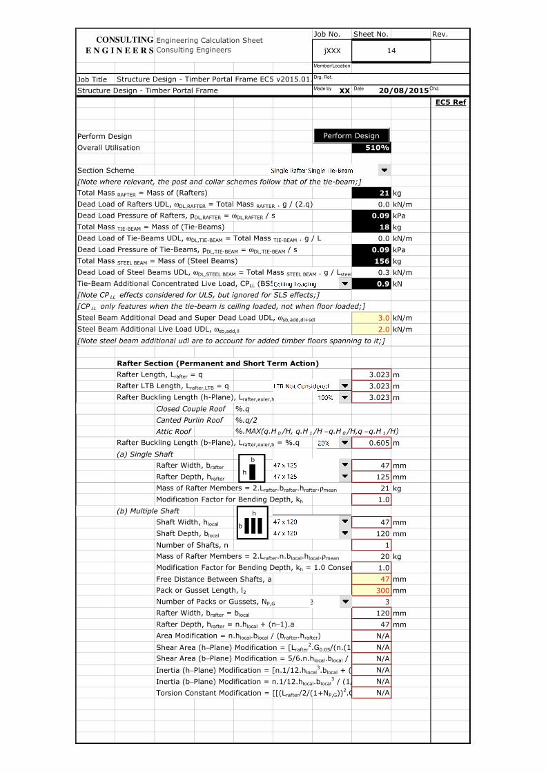
Perform Design
Overall Utilisation 510%
Section Scheme
[Note where relevant, the post and collar schemes follow that of the tie-beam;]
Total Mass RAFTER = Mass of (Rafters) 21 kg
Dead Load of Rafters UDL, ωDL,RAFTER = Total Mass RAFTER . g / (2.q) 0.0 kN/m
Dead Load Pressure of Rafters, pDL,RAFTER = ωDL,RAFTER / s 0.09 kPa
Total Mass TIE-BEAM = Mass of (Tie-Beams) 18 kg
Dead Load of Tie-Beams UDL, ωDL,TIE-BEAM = Total Mass TIE-BEAM . g / L 0.0 kN/m
Dead Load Pressure of Tie-Beams, pDL,TIE-BEAM = ωDL,TIE-BEAM / s 0.09 kPa
Total Mass STEEL BEAM = Mass of (Steel Beams) 156 kg
Dead Load of Steel Beams UDL, ωDL,STEEL BEAM = Total Mass STEEL BEAM . g / Lsteelbeam 0.3 kN/m
Tie-Beam Additional Concentrated Live Load, CPLL (BS5268-7.3:1989) 0.9 kN
[Note CP LL effects considered for ULS, but ignored for SLS effects;]
[CP LL only features when the tie-beam is ceiling loaded, not when floor loaded;]
Steel Beam Additional Dead and Super Dead Load UDL, ωsb,add,dl+sdl 3.0 kN/m
Steel Beam Additional Live Load UDL, ωsb,add,ll 2.0 kN/m
[Note steel beam additional udl are to account for added timber floors spanning to it;]
Rafter Section (Permanent and Short Term Action)
Rafter Length, Lrafter = q 3.023 m
Rafter LTB Length, Lrafter,LTB = q 3.023 m
Rafter Buckling Length (h-Plane), Lrafter,euler,h 3.023 m
Closed Couple Roof %.q
Canted Purlin Roof %.q/2
Attic Roof %.MAX(q.H 0 /H, q.H 1 /H − q.H 0 /H,q − q.H 1 /H)
Rafter Buckling Length (b-Plane), Lrafter,euler,b = %.q 0.605 m
(a) Single Shaft
Rafter Width, brafter 47 mm
Rafter Depth, hrafter 125 mm
Mass of Rafter Members = 2.Lrafter.brafter.hrafter.ρmean 21 kg
Modification Factor for Bending Depth, kh 1.0
(b) Multiple Shaft
Shaft Width, hlocal 47 mm
Shaft Depth, blocal 120 mm
Number of Shafts, n 1
Mass of Rafter Members = 2.Lrafter.n.blocal.hlocal.ρmean 20 kg
Modification Factor for Bending Depth, kh = 1.0 Conservatively1.0
Free Distance Between Shafts, a 47 mm
Pack or Gusset Length, l2 300 mm
Number of Packs or Gussets, NP,G 3
Rafter Width, brafter = blocal 120 mm
Rafter Depth, hrafter = n.hlocal + (n−1).a 47 mm
Area Modification = n.hlocal.blocal / (brafter.hrafter) N/A
Shear Area (h−Plane) Modification = [Lrafter2.G0.05/(n.(1+N N/A
Shear Area (b−Plane) Modification = 5/6.n.hlocal.blocal / (5/6.b N/A
Inertia (h−Plane) Modification = [n.1/12.hlocal3.blocal + (n-1).h N/A
Inertia (b−Plane) Modification = n.1/12.hlocal.blocal3 / (1/12.b N/A
Torsion Constant Modification = [[(Lrafter/2/(1+NP,G))2.G/(3/2.((n-1).(a+hN/A
jXXX 14
Structure Design - Timber Portal Frame 20/08/2015
CONSULTING
E N G I N E E R S
Structure Design - Timber Portal Frame EC5 v2015.01.xlsm
Engineering Calculation Sheet Consulting Engineers
Perform Design
h
b
h
b
Made by Date Chd.
Drg. Ref.
Member/Location
Job No. Sheet No. Rev.
Job Title
XX
EC5 Ref
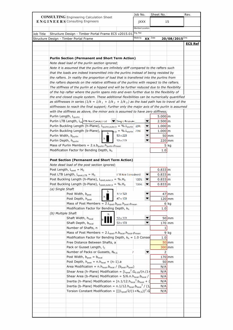
Purlin Section (Permanent and Short Term Action)
Note dead load of the purlin section ignored;
Note it is assumed that the purlins are infinitely stiff compared to the rafters such
that the loads are indeed transmitted into the purlins instead of being resisted by
the rafters. In reality the proportion of load that is transfered into the purlins from
the rafters depends on the relative stiffness of the purlins with respect to the rafters.
The stiffness of the purlin at a hipped end will be further reduced due to the flexibility
of the hip rafter where the purlin spans into and even further due to the flexibility of
the end closed couple system. These additional flexibilities can be numerically quantified
as stiffnesses in series (1/k = 1/k 1 + 1/k 2 + 1/k 3 ) as the load path has to travel all the
stiffnesses to reach the final support; Further only the major axis of the purlin is assumed
with the stiffness as above, the minor axis is assumed to have zero stiffness;
Purlin Length, Lpurlin 5.000 m
Purlin LTB Length, Lpurlin,LTB = Lpurlin / (1 + LTB Restraints) 2.500 m
Purlin Buckling Length (h-Plane), Lpurlin,euler,h = %.Lpurlin 1.000 m
Purlin Buckling Length (b-Plane), Lpurlin,euler,b = %.Lpurlin 1.000 m
Purlin Width, bpurlin 50 mm
Purlin Depth, hpurlin 220 mm
Mass of Purlin Members = 2.s.bpurlin.hpurlin.ρmean 5 kg
Modification Factor for Bending Depth, kh 1.0
Post Section (Permanent and Short Term Action)
Note dead load of the post section ignored;
Post Length, Lpost = H0 0.833 m
Post LTB Length, Lpost,LTB = H0 0.833 m
Post Buckling Length (h-Plane), Lpost,euler,h = %.H0 0.833 m
Post Buckling Length (b-Plane), Lpost,euler,b = %.H0 0.833 m
(a) Single Shaft
Post Width, bpost 47 mm
Post Depth, hpost 120 mm
Mass of Post Members = 2.Lpost.bpost.hpost.ρmean 6 kg
Modification Factor for Bending Depth, kh 1.0
(b) Multiple Shaft
Shaft Width, hlocal 50 mm
Shaft Depth, blocal 170 mm
Number of Shafts, n 1
Mass of Post Members = 2.Lpost.n.blocal.hlocal.ρmean 9 kg
Modification Factor for Bending Depth, kh = 1.0 Conservatively1.0
Free Distance Between Shafts, a 50 mm
Pack or Gusset Length, l2 300 mm
Number of Packs or Gussets, NP,G 2
Post Width, bpost = blocal 170 mm
Post Depth, hpost = n.hlocal + (n−1).a 50 mm
Area Modification = n.hlocal.blocal / (bpost.hpost) N/A
Shear Area (h−Plane) Modification = [Lpost2.G0.05/(n.(1+N N/A
Shear Area (b−Plane) Modification = 5/6.n.hlocal.blocal / (5/6.b N/A
Inertia (h−Plane) Modification = [n.1/12.hlocal3.blocal + (n-1).h N/A
Inertia (b−Plane) Modification = n.1/12.hlocal.blocal3 / (1/12.b N/A
Torsion Constant Modification = [[(Lpost/2/(1+NP,G))2.G/(3/2.((n-1).(a+hN/A
Structure Design - Timber Portal Frame EC5 v2015.01.xlsm
15
Engineering Calculation Sheet Consulting Engineers jXXX
20/08/2015Structure Design - Timber Portal Frame
CONSULTING
E N G I N E E R S
h
b
h
b
h
b
Made by Date Chd.
Drg. Ref.
Member/Location
Job No. Sheet No. Rev.
Job Title
XX
EC5 Ref
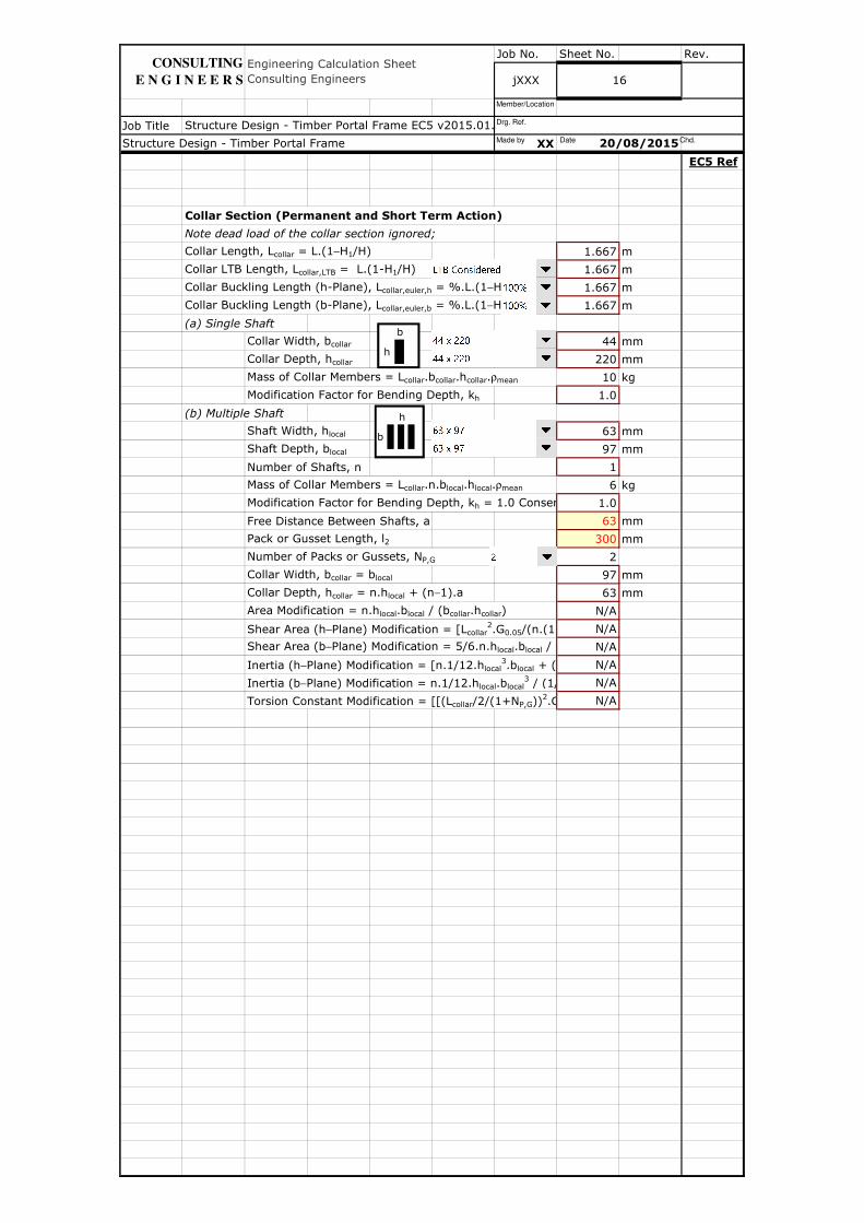
Collar Section (Permanent and Short Term Action)
Note dead load of the collar section ignored;
Collar Length, Lcollar = L.(1−H1/H) 1.667 m
Collar LTB Length, Lcollar,LTB = L.(1-H1/H) 1.667 m
Collar Buckling Length (h-Plane), Lcollar,euler,h = %.L.(1−H1/H) 1.667 m
Collar Buckling Length (b-Plane), Lcollar,euler,b = %.L.(1−H1/H) 1.667 m
(a) Single Shaft
Collar Width, bcollar 44 mm
Collar Depth, hcollar 220 mm
Mass of Collar Members = Lcollar.bcollar.hcollar.ρmean 10 kg
Modification Factor for Bending Depth, kh 1.0
(b) Multiple Shaft
Shaft Width, hlocal 63 mm
Shaft Depth, blocal 97 mm
Number of Shafts, n 1
Mass of Collar Members = Lcollar.n.blocal.hlocal.ρmean 6 kg
Modification Factor for Bending Depth, kh = 1.0 Conservatively1.0
Free Distance Between Shafts, a 63 mm
Pack or Gusset Length, l2 300 mm
Number of Packs or Gussets, NP,G 2
Collar Width, bcollar = blocal 97 mm
Collar Depth, hcollar = n.hlocal + (n−1).a 63 mm
Area Modification = n.hlocal.blocal / (bcollar.hcollar) N/A
Shear Area (h−Plane) Modification = [Lcollar2.G0.05/(n.(1+N N/A
Shear Area (b−Plane) Modification = 5/6.n.hlocal.blocal / (5/6.b N/A
Inertia (h−Plane) Modification = [n.1/12.hlocal3.blocal + (n-1).h N/A
Inertia (b−Plane) Modification = n.1/12.hlocal.blocal3 / (1/12.b N/A
Torsion Constant Modification = [[(Lcollar/2/(1+NP,G))2.G/(3/2.((n-1).(a+hN/A
Structure Design - Timber Portal Frame EC5 v2015.01.xlsm
Structure Design - Timber Portal Frame 20/08/2015
16
Engineering Calculation Sheet Consulting Engineers jXXX
CONSULTING
E N G I N E E R S
h
b
h
b
Made by Date Chd.
Drg. Ref.
Member/Location

Job No. Sheet No. Rev.
Job Title
XX
EC5 Ref
Tie-Beam Section (Permanent and Medium Term Action)
Tie-Beam Length, Ltie-beam = L 5.000 m
Tie-Beam LTB Length, Ltie-beam,LTB = L / (1 + Struttings) 2.500 m
Tie-Beam Buckling Length (h-Plane), Ltie-beam,euler,h = %.L 5.000 m
Tie-Beam Buckling Length (b-Plane), Ltie-beam,euler,b = %.L 1.000 m
(a) Single Shaft
Tie-Beam Width, btie-beam 47 mm
Tie-Beam Depth, htie-beam 125 mm
Mass of Tie-Beam Members = Ltie-beam.btie-beam.htie-beam.ρ 18 kg
Modification Factor for Bending Depth, kh 1.0
(b) Multiple Shaft
Shaft Width, hlocal 47 mm
Shaft Depth, blocal 145 mm
Number of Shafts, n 1
Mass of Tie-Beam Members = Ltie-beam.n.blocal.hlocal.ρmean 20 kg
Modification Factor for Bending Depth, kh = 1.0 Conservatively1.0
Free Distance Between Shafts, a 47 mm
Pack or Gusset Length, l2 300 mm
Number of Packs or Gussets, NP,G 2
Tie-Beam Width, btie-beam = blocal 145 mm
Tie-Beam Depth, htie-beam = n.hlocal + (n−1).a 47 mm
Area Modification = n.hlocal.blocal / (btie-beam.htie-beam) N/A
Shear Area (h−Plane) Modification = [Ltie-beam2.G0.05/(n.(1+N N/A
Shear Area (b−Plane) Modification = 5/6.n.hlocal.blocal / (5/6.b N/A
Inertia (h−Plane) Modification = [n.1/12.hlocal3.blocal + (n-1).h N/A
Inertia (b−Plane) Modification = n.1/12.hlocal.blocal3 / (1/12.b N/A
Torsion Constant Modification = [[(Ltie-beam/2/(1+NP,G)) N/A
Binder Section (Permanent and Medium Term Action)
Note dead load of the binder section ignored;
Note it is assumed that the binders are infinitely stiff compared to the tie-beams such
that the loads are indeed transmitted into the binders instead of being resisted by the
tie-beams. In reality the proportion of load that is transfered into the binders from the
tie-beams depends on the relative stiffness of the binders with respect to the tie-beams;
Binder Length, Lbinder 3.000 m
Binder LTB Length, Lbinder,LTB = Lbinder / (1 + LTB Restraints) 1.500 m
Binder Buckling Length (h-Plane), Lbinder,euler,h = %.Lbinder 0.600 m
Binder Buckling Length (b-Plane), Lbinder,euler,b = %.Lbinder 0.600 m
Binder Width, bbinder 50 mm
Binder Depth, hbinder 195 mm
Mass of Binder Members = NBIND.s.bbinder.hbinder.ρmean 2 kg
Modification Factor for Bending Depth, kh 1.0
Structure Design - Timber Portal Frame
Structure Design - Timber Portal Frame EC5 v2015.01.xlsm
20/08/2015
Engineering Calculation Sheet Consulting Engineers jXXX 17
CONSULTING
E N G I N E E R S
h
b
h
b
h
b
Made by Date Chd.
Drg. Ref.
Member/Location
Job No. Sheet No. Rev.
Job Title
XX
EC5 Ref
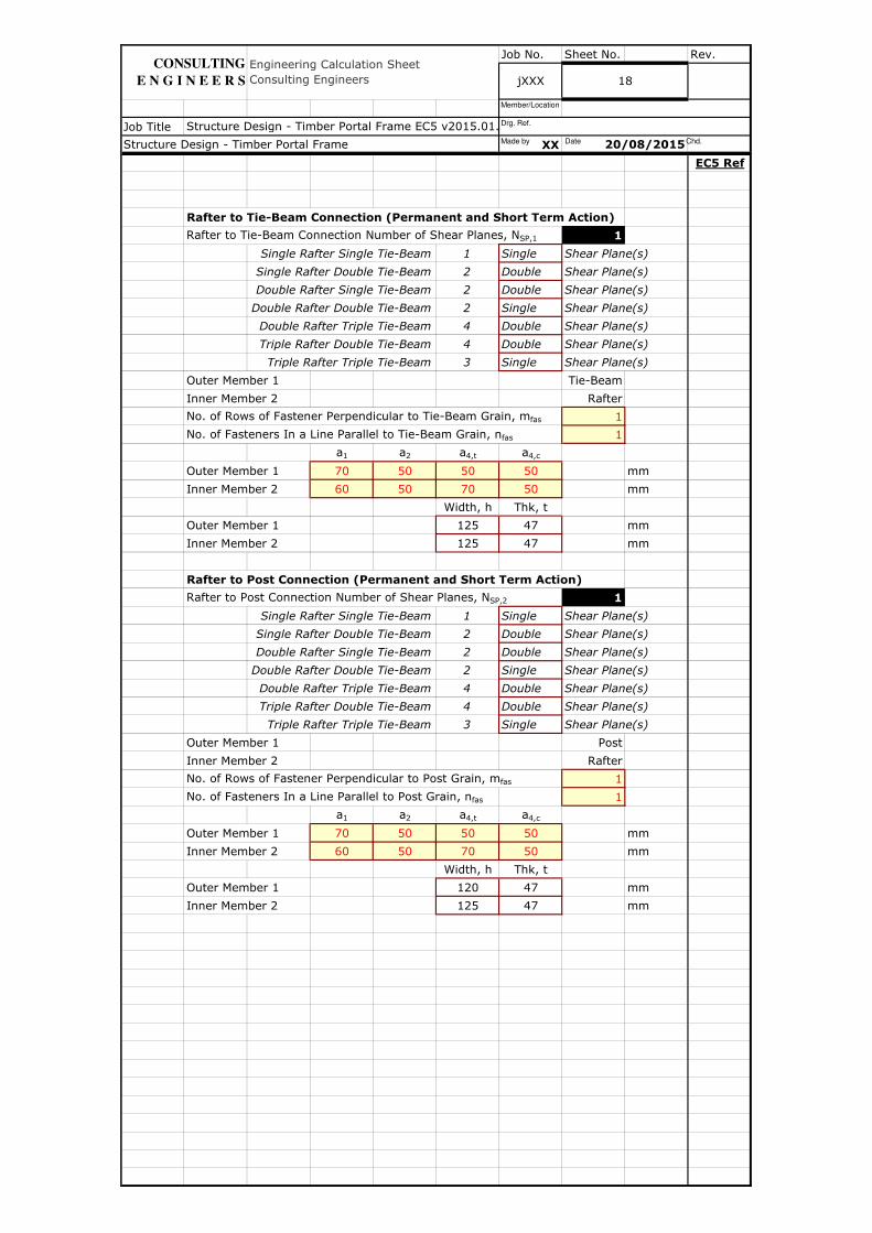
Rafter to Tie-Beam Connection (Permanent and Short Term Action)
Rafter to Tie-Beam Connection Number of Shear Planes, NSP,1 1
Single Rafter Single Tie-Beam 1 Single Shear Plane(s)
Single Rafter Double Tie-Beam 2 Double Shear Plane(s)
Double Rafter Single Tie-Beam 2 Double Shear Plane(s)
Double Rafter Double Tie-Beam 2 Single Shear Plane(s)
Double Rafter Triple Tie-Beam 4 Double Shear Plane(s)
Triple Rafter Double Tie-Beam 4 Double Shear Plane(s)
Triple Rafter Triple Tie-Beam 3 Single Shear Plane(s)
Outer Member 1 Tie-Beam
Inner Member 2 Rafter
No. of Rows of Fastener Perpendicular to Tie-Beam Grain, mfas 1
No. of Fasteners In a Line Parallel to Tie-Beam Grain, nfas 1
a1 a2 a4,t a4,c
Outer Member 1 70 50 50 50 mm
Inner Member 2 60 50 70 50 mm
Width, h Thk, t
Outer Member 1 125 47 mm
Inner Member 2 125 47 mm
Rafter to Post Connection (Permanent and Short Term Action)
Rafter to Post Connection Number of Shear Planes, NSP,2 1
Single Rafter Single Tie-Beam 1 Single Shear Plane(s)
Single Rafter Double Tie-Beam 2 Double Shear Plane(s)
Double Rafter Single Tie-Beam 2 Double Shear Plane(s)
Double Rafter Double Tie-Beam 2 Single Shear Plane(s)
Double Rafter Triple Tie-Beam 4 Double Shear Plane(s)
Triple Rafter Double Tie-Beam 4 Double Shear Plane(s)
Triple Rafter Triple Tie-Beam 3 Single Shear Plane(s)
Outer Member 1 Post
Inner Member 2 Rafter
No. of Rows of Fastener Perpendicular to Post Grain, mfas 1
No. of Fasteners In a Line Parallel to Post Grain, nfas 1
a1 a2 a4,t a4,c
Outer Member 1 70 50 50 50 mm
Inner Member 2 60 50 70 50 mm
Width, h Thk, t
Outer Member 1 120 47 mm
Inner Member 2 125 47 mm
Structure Design - Timber Portal Frame 20/08/2015
Structure Design - Timber Portal Frame EC5 v2015.01.xlsm
jXXX 18
Engineering Calculation Sheet Consulting Engineers
CONSULTING
E N G I N E E R S
Made by Date Chd.
Drg. Ref.
Member/Location
Job No. Sheet No. Rev.
Job Title
XX
EC5 Ref
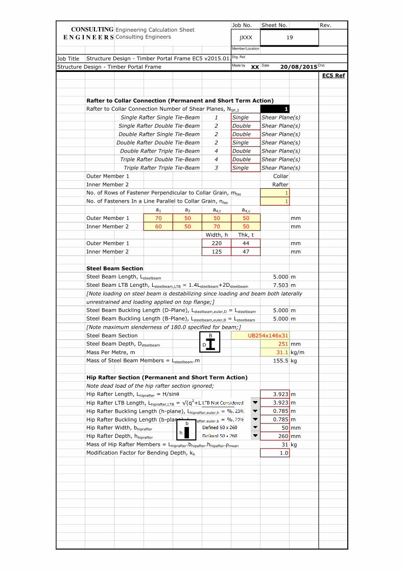
Rafter to Collar Connection (Permanent and Short Term Action)
Rafter to Collar Connection Number of Shear Planes, NSP,3 1
Single Rafter Single Tie-Beam 1 Single Shear Plane(s)
Single Rafter Double Tie-Beam 2 Double Shear Plane(s)
Double Rafter Single Tie-Beam 2 Double Shear Plane(s)
Double Rafter Double Tie-Beam 2 Single Shear Plane(s)
Double Rafter Triple Tie-Beam 4 Double Shear Plane(s)
Triple Rafter Double Tie-Beam 4 Double Shear Plane(s)
Triple Rafter Triple Tie-Beam 3 Single Shear Plane(s)
Outer Member 1 Collar
Inner Member 2 Rafter
No. of Rows of Fastener Perpendicular to Collar Grain, mfas 1
No. of Fasteners In a Line Parallel to Collar Grain, nfas 1
a1 a2 a4,t a4,c
Outer Member 1 70 50 50 50 mm
Inner Member 2 60 50 70 50 mm
Width, h Thk, t
Outer Member 1 220 44 mm
Inner Member 2 125 47 mm
Steel Beam Section
Steel Beam Length, Lsteelbeam 5.000 m
Steel Beam LTB Length, Lsteelbeam,LTB = 1.4Lsteelbeam+2Dsteelbeam 7.503 m
[Note loading on steel beam is destabilizing since loading and beam both laterally
unrestrained and loading applied on top flange;]
Steel Beam Buckling Length (D-Plane), Lsteelbeam,euler,D = Lsteelbeam 5.000 m
Steel Beam Buckling Length (B-Plane), Lsteelbeam,euler,B = Lsteelbeam 5.000 m
[Note maximum slenderness of 180.0 specified for beam;]
Steel Beam Section UB254x146x31
Steel Beam Depth, Dsteelbeam 251 mm
Mass Per Metre, m 31.1 kg/m
Mass of Steel Beam Members = Lsteelbeam.m 155.5 kg
Hip Rafter Section (Permanent and Short Term Action)
Note dead load of the hip rafter section ignored;
Hip Rafter Length, Lhiprafter = H/sinθ 3.923 m
Hip Rafter LTB Length, Lhiprafter,LTB = √(q2+L2/4) 3.923 m
Hip Rafter Buckling Length (h-plane), Lhiprafter,euler,h = %.√(q2+L2/4) 0.785 m
Hip Rafter Buckling Length (b-plane), Lhiprafter,euler,b = %.√(q2+L2/4) 0.785 m
Hip Rafter Width, bhiprafter 50 mm
Hip Rafter Depth, hhiprafter 260 mm
Mass of Hip Rafter Members = Lhiprafter.bhipafter.hhipafter.ρmean 31 kg
Modification Factor for Bending Depth, kh 1.0
Structure Design - Timber Portal Frame 20/08/2015
Structure Design - Timber Portal Frame EC5 v2015.01.xlsm
19
Engineering Calculation Sheet Consulting Engineers jXXX
CONSULTING
E N G I N E E R S
D
B
h
b
Made by Date Chd.
Drg. Ref.
Member/Location
Job No. Sheet No. Rev.
Job Title
XX
EC5 Ref
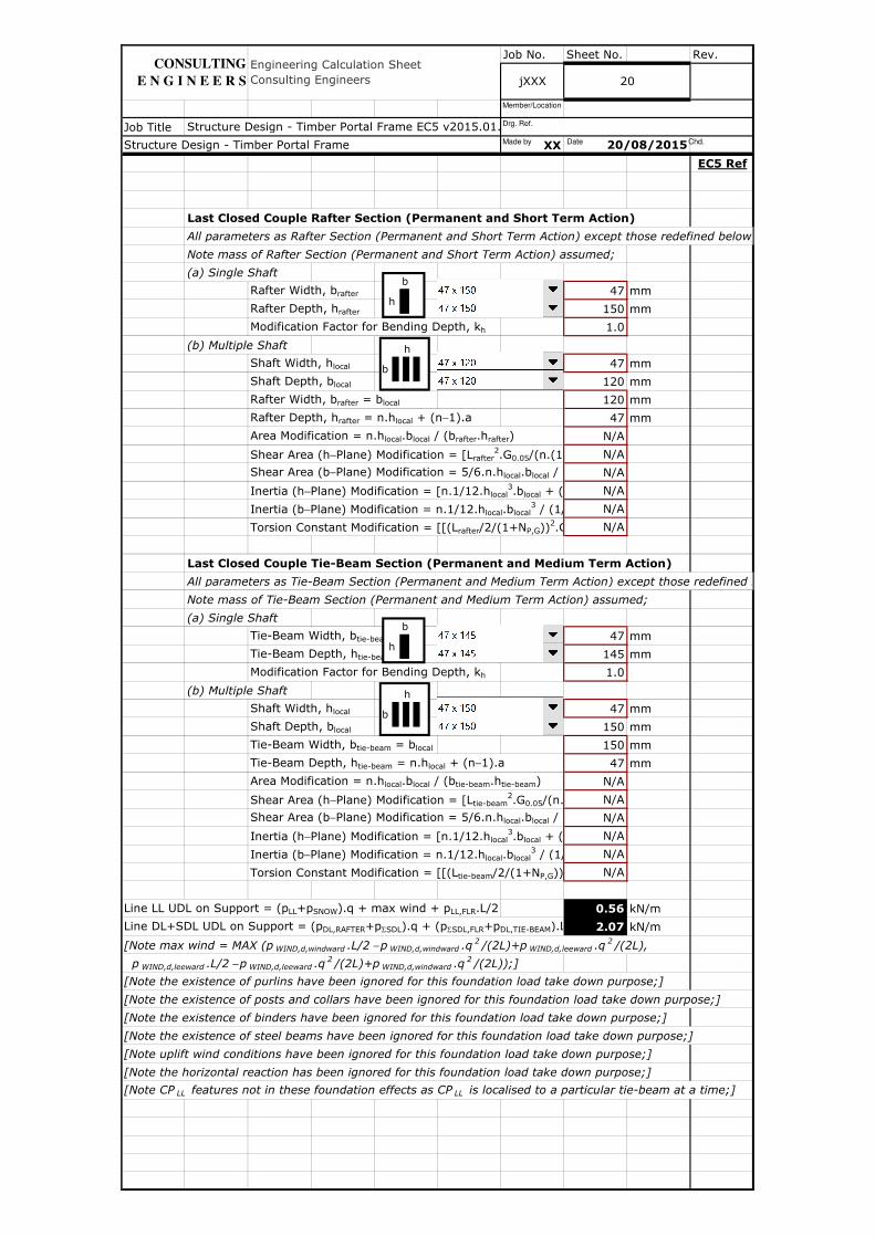
Last Closed Couple Rafter Section (Permanent and Short Term Action)
All parameters as Rafter Section (Permanent and Short Term Action) except those redefined below;
Note mass of Rafter Section (Permanent and Short Term Action) assumed;
(a) Single Shaft
Rafter Width, brafter 47 mm
Rafter Depth, hrafter 150 mm
Modification Factor for Bending Depth, kh 1.0
(b) Multiple Shaft
Shaft Width, hlocal 47 mm
Shaft Depth, blocal 120 mm
Rafter Width, brafter = blocal 120 mm
Rafter Depth, hrafter = n.hlocal + (n−1).a 47 mm
Area Modification = n.hlocal.blocal / (brafter.hrafter) N/A
Shear Area (h−Plane) Modification = [Lrafter2.G0.05/(n.(1+N N/A
Shear Area (b−Plane) Modification = 5/6.n.hlocal.blocal / (5/6.b N/A
Inertia (h−Plane) Modification = [n.1/12.hlocal3.blocal + (n-1).h N/A
Inertia (b−Plane) Modification = n.1/12.hlocal.blocal3 / (1/12.b N/A
Torsion Constant Modification = [[(Lrafter/2/(1+NP,G))2.G/(3/2.((n-1).(a+hN/A
Last Closed Couple Tie-Beam Section (Permanent and Medium Term Action)
All parameters as Tie-Beam Section (Permanent and Medium Term Action) except those redefined below;
Note mass of Tie-Beam Section (Permanent and Medium Term Action) assumed;
(a) Single Shaft
Tie-Beam Width, btie-beam 47 mm
Tie-Beam Depth, htie-beam 145 mm
Modification Factor for Bending Depth, kh 1.0
(b) Multiple Shaft
Shaft Width, hlocal 47 mm
Shaft Depth, blocal 150 mm
Tie-Beam Width, btie-beam = blocal 150 mm
Tie-Beam Depth, htie-beam = n.hlocal + (n−1).a 47 mm
Area Modification = n.hlocal.blocal / (btie-beam.htie-beam) N/A
Shear Area (h−Plane) Modification = [Ltie-beam2.G0.05/(n.(1+N N/A
Shear Area (b−Plane) Modification = 5/6.n.hlocal.blocal / (5/6.b N/A
Inertia (h−Plane) Modification = [n.1/12.hlocal3.blocal + (n-1).h N/A
Inertia (b−Plane) Modification = n.1/12.hlocal.blocal3 / (1/12.b N/A
Torsion Constant Modification = [[(Ltie-beam/2/(1+NP,G)) N/A
Line LL UDL on Support = (pLL+pSNOW).q + max wind + pLL,FLR.L/2 0.56 kN/m
Line DL+SDL UDL on Support = (pDL,RAFTER+pΣSDL).q + (pΣSDL,FLR+pDL,TIE-BEAM).L/2 2.07 kN/m
[Note max wind = MAX (p WIND,d,windward .L/2 − p WIND,d,windward .q 2 /(2L)+p WIND,d,leeward .q 2 /(2L),
p WIND,d,leeward .L/2 − p WIND,d,leeward .q 2 /(2L)+p WIND,d,windward .q 2 /(2L));]
[Note the existence of purlins have been ignored for this foundation load take down purpose;]
[Note the existence of posts and collars have been ignored for this foundation load take down purpose;]
[Note the existence of binders have been ignored for this foundation load take down purpose;]
[Note the existence of steel beams have been ignored for this foundation load take down purpose;]
[Note uplift wind conditions have been ignored for this foundation load take down purpose;]
[Note the horizontal reaction has been ignored for this foundation load take down purpose;]
[Note CP LL features not in these foundation effects as CP LL is localised to a particular tie-beam at a time;]
Structure Design - Timber Portal Frame EC5 v2015.01.xlsm
20
Structure Design - Timber Portal Frame
Engineering Calculation Sheet Consulting Engineers jXXX
20/08/2015
CONSULTING
E N G I N E E R S
h
b
h
b
h
b
h
b
Made by Date Chd.
Drg. Ref.
Member/Location
Job No. Sheet No. Rev.
Job Title
XX
EC5 Ref
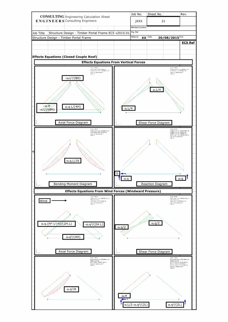
Effects Equations (Closed Couple Roof)
All parameters as Rafter Section (Permanent and Short Term Action) except those redefined below;
All parameters as Tie-Beam Section (Permanent and Medium Term Action) except those redefined below;
Engineering Calculation Sheet Consulting Engineers jXXX 21
20/08/2015Structure Design - Timber Portal Frame
Structure Design - Timber Portal Frame EC5 v2015.01.xlsm
CONSULTING
E N G I N E E R S
Axial Force Diagram
ω.q.L/(4H)−ω.H−ω.L2/(8H)
−ω.L2/(8H)
Shear Force Diagram
ω.L/4
ω.L/4
Bending Moment Diagram
ω.q.L/16
Reaction Diagram
ω.q ω.q
0
Effects Equations From Vertical Forces
ω.L/2−ω.q2/(2L) ω.q2/(2L)
ω.H
ω.q2/8
Shear Force Diagram
ω.q/2
ω.q/2
Axial Force Diagram
−ω.q3/(2H.L)
ω.q2/(4H)
ω.q.(H2−L2/4)/(2H.L)
Effects Equations From Wind Forces (Windward Pressure)
Wind
Made by Date Chd.
Drg. Ref.
Member/Location
Job No. Sheet No. Rev.
Job Title
XX
EC5 Ref
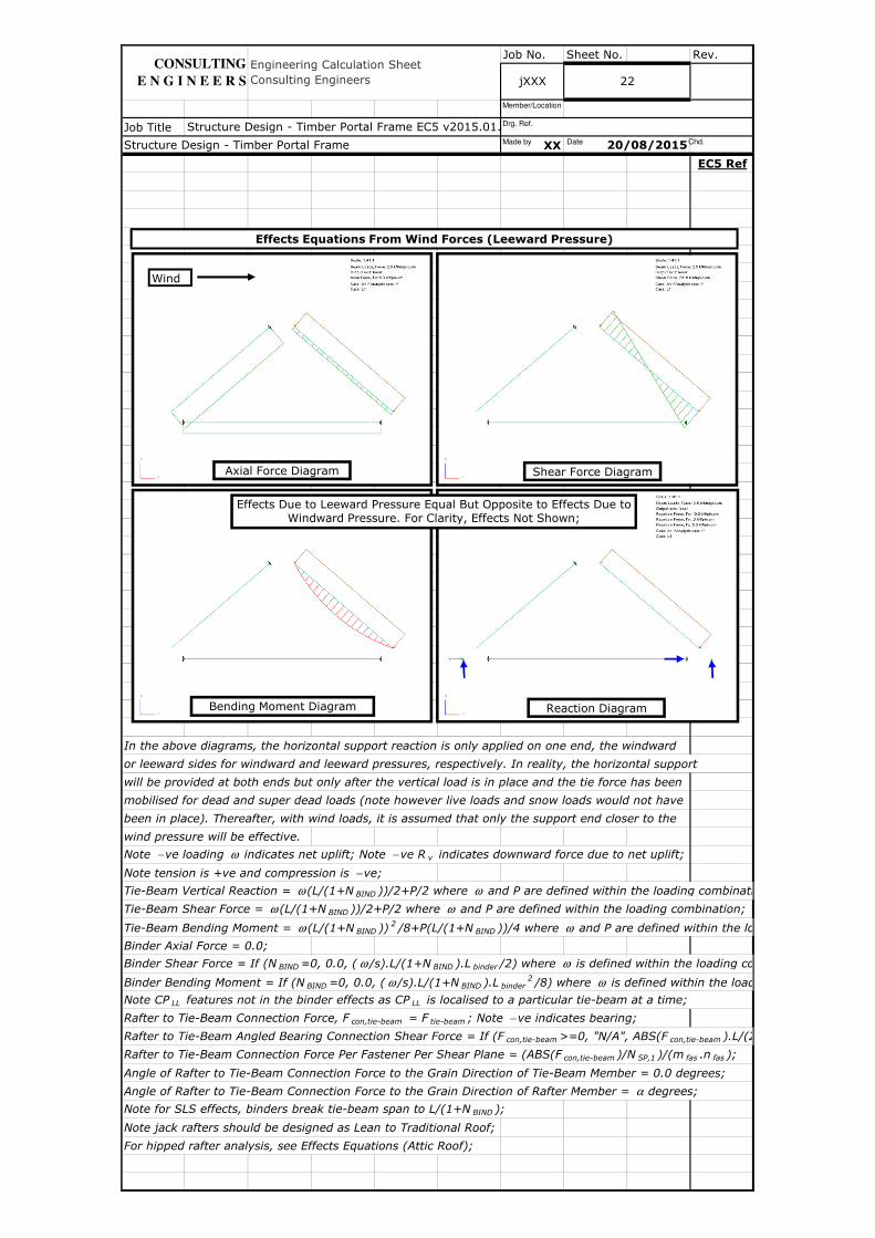
In the above diagrams, the horizontal support reaction is only applied on one end, the windward
or leeward sides for windward and leeward pressures, respectively. In reality, the horizontal support
will be provided at both ends but only after the vertical load is in place and the tie force has been
mobilised for dead and super dead loads (note however live loads and snow loads would not have
been in place). Thereafter, with wind loads, it is assumed that only the support end closer to the
wind pressure will be effective.
Note − ve loading ω indicates net uplift; Note − ve R v indicates downward force due to net uplift;
Note tension is +ve and compression is − ve;
Tie-Beam Vertical Reaction = ω (L/(1+N BIND ))/2+P/2 where ω and P are defined within the loading combination;
Tie-Beam Shear Force = ω (L/(1+N BIND ))/2+P/2 where ω and P are defined within the loading combination;
Tie-Beam Bending Moment = ω (L/(1+N BIND )) 2 /8+P(L/(1+N BIND ))/4 where ω and P are defined within the loading combination;
Binder Axial Force = 0.0;
Binder Shear Force = If (N BIND =0, 0.0, ( ω /s).L/(1+N BIND ).L binder /2) where ω is defined within the loading combination;
Binder Bending Moment = If (N BIND =0, 0.0, ( ω /s).L/(1+N BIND ).L binder2 /8) where ω is defined within the loading combination;
Note CP LL features not in the binder effects as CP LL is localised to a particular tie-beam at a time;
Rafter to Tie-Beam Connection Force, F con,tie-beam = F tie-beam ; Note − ve indicates bearing;
Rafter to Tie-Beam Angled Bearing Connection Shear Force = If (F con,tie-beam >=0, "N/A", ABS(F con,tie-beam ).L/(2q));
Rafter to Tie-Beam Connection Force Per Fastener Per Shear Plane = (ABS(F con,tie-beam )/N SP,1 )/(m fas .n fas );
Angle of Rafter to Tie-Beam Connection Force to the Grain Direction of Tie-Beam Member = 0.0 degrees;
Angle of Rafter to Tie-Beam Connection Force to the Grain Direction of Rafter Member = α degrees;
Note for SLS effects, binders break tie-beam span to L/(1+N BIND );
Note jack rafters should be designed as Lean to Traditional Roof;
For hipped rafter analysis, see Effects Equations (Attic Roof);
Structure Design - Timber Portal Frame EC5 v2015.01.xlsm
Structure Design - Timber Portal Frame 20/08/2015
Engineering Calculation Sheet Consulting Engineers jXXX
CONSULTING
E N G I N E E R S 22
Effects Equations From Wind Forces (Leeward Pressure)
Reaction DiagramBending Moment Diagram
Shear Force DiagramAxial Force Diagram
Wind
Effects Due to Leeward Pressure Equal But Opposite to Effects Due to Windward Pressure. For Clarity, Effects Not Shown;
Made by Date Chd.
Drg. Ref.
Member/Location
Job No. Sheet No. Rev.
Job Title
XX
EC5 Ref
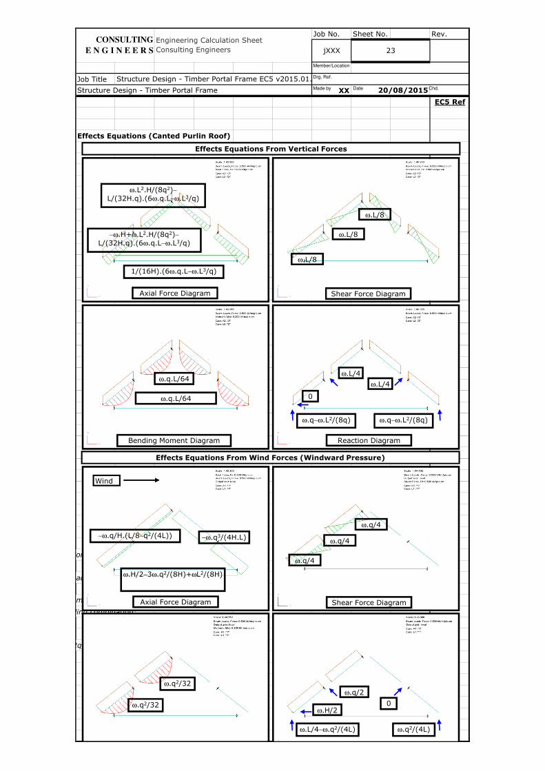
Effects Equations (Canted Purlin Roof)
and P are defined within the loading combination;
and P are defined within the loading combination;
is defined within the loading combination;
is defined within the loading combination;
).L/(2q));
jXXX
Engineering Calculation Sheet Consulting Engineers
Structure Design - Timber Portal Frame EC5 v2015.01.xlsm
Structure Design - Timber Portal Frame 20/08/2015
CONSULTING
E N G I N E E R S 23
Effects Equations From Vertical Forces
Reaction Diagram
ω.q−ω.L2/(8q)
ω.L/4
ω.L/4
ω.q−ω.L2/(8q)
Axial Force Diagram
1/(16H).(6ω.q.L−ω.L3/q)
−ω.H+ω.L2.H/(8q2)−
L/(32H.q).(6ω.q.L−ω.L3/q)
ω.L2.H/(8q2)−
L/(32H.q).(6ω.q.L−ω.L3/q)
Bending Moment Diagram
ω.q.L/64
ω.q.L/64
Shear Force Diagram
ω.L/8
ω.L/8
ω.L/8
0
ω.L/4−ω.q2/(4L) ω.q2/(4L)
ω.q/2ω.q2/32
Shear Force Diagram
ω.q/4
ω.q/4
Axial Force Diagram
−ω.q3/(4H.L)
ω.H/2−3ω.q2/(8H)+ωL2/(8H)
−ω.q/H.(L/8−q2/(4L))
Effects Equations From Wind Forces (Windward Pressure)
Wind
0ω.H/2
ω.q2/32
ω.q/4
Made by Date Chd.
Drg. Ref.
Member/Location
Job No. Sheet No. Rev.
Job Title
XX
EC5 Ref
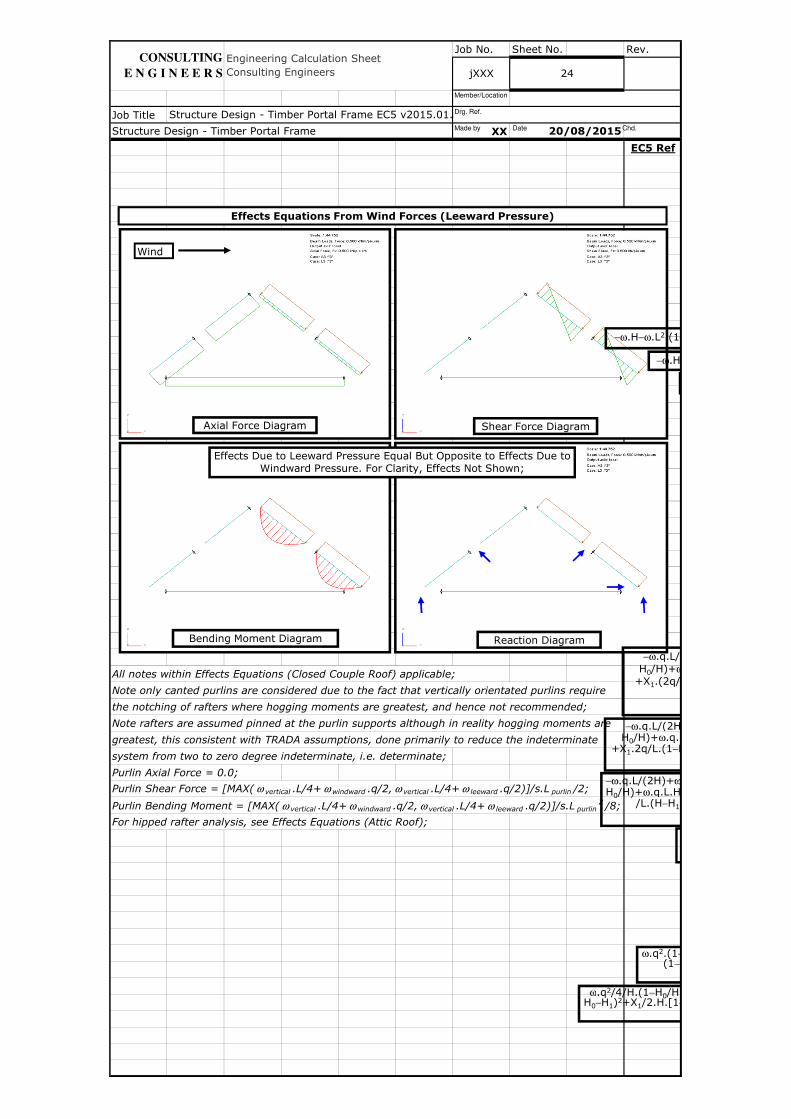
All notes within Effects Equations (Closed Couple Roof) applicable;
Note only canted purlins are considered due to the fact that vertically orientated purlins require
the notching of rafters where hogging moments are greatest, and hence not recommended;
Note rafters are assumed pinned at the purlin supports although in reality hogging moments are
greatest, this consistent with TRADA assumptions, done primarily to reduce the indeterminate
system from two to zero degree indeterminate, i.e. determinate;
Purlin Axial Force = 0.0;
Purlin Shear Force = [MAX( ω vertical .L/4+ ω windward .q/2, ω vertical .L/4+ ω leeward .q/2)]/s.L purlin /2;
Purlin Bending Moment = [MAX( ω vertical .L/4+ ω windward .q/2, ω vertical .L/4+ ω leeward .q/2)]/s.L purlin2 /8;
For hipped rafter analysis, see Effects Equations (Attic Roof);
Structure Design - Timber Portal Frame EC5 v2015.01.xlsm
Engineering Calculation Sheet Consulting Engineers
20/08/2015Structure Design - Timber Portal Frame
CONSULTING
E N G I N E E R S 24jXXX
Effects Equations From Wind Forces (Leeward Pressure)
Reaction DiagramBending Moment Diagram
Shear Force DiagramAxial Force Diagram
Wind
Effects Due to Leeward Pressure Equal But Opposite to Effects Due to Windward Pressure. For Clarity, Effects Not Shown;
−ω.H/2
−ω.H−ω.L2.(1−
ω.q2.(1−(1−H
ω.q2/4/H.(1−H0/H).(2HH0−H1)2+X1/2.H.[1−
−ω.q.L/(2H)+ωH0/H)+ω.q.L.H
/L.(H−H1)/(H
−ω.q.L/(2H)+H0/H)+ω.q.L.H
+X1.2q/L.(1−H
−ω.q.L/(2H)+H0/H)+ω
+X1.(2q/L.(1
Made by Date Chd.
Drg. Ref.
Member/Location
Job No. Sheet No. Rev.
Job Title
XX
EC5 Ref
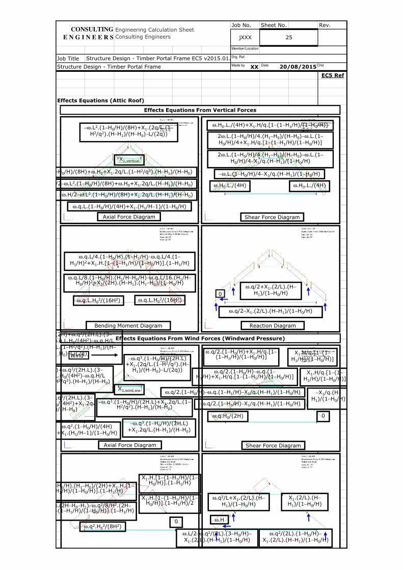
Effects Equations (Attic Roof)
Engineering Calculation Sheet Consulting Engineers jXXX 25
20/08/2015
Structure Design - Timber Portal Frame EC5 v2015.01.xlsm
Structure Design - Timber Portal Frame
CONSULTING
E N G I N E E R S
Effects Equations From Vertical Forces
Reaction Diagram
Axial Force Diagram
Bending Moment Diagram
Shear Force Diagram
ω.q.L.(1−H0/H)/(4H)+X1.(H1/H−1)/(1−H0/H)
ω.q/2−X1.(2/L).(H−H1)/(1−H0/H)
0
ω.q/2+X1.(2/L).(H−
H1)/(1−H0/H)
−ω.L.(1−H0/H)/4−X1/q.(H−H1)/(1−H0/H)
ω.H0.L./(4H) ω.H0.L./(4H)
ω.H0.L./(4H)+X1.H/q.[1−(1−H1/H)/(1−H0/H)]
2ω.L.(1−H0/H)/4.(H1−H0)/(H−H0)−ω.L.(1−
H0/H)/4+X1.H/q.[1−(1−H1/H)/(1−H0/H)]
2ω.L.(1−H0/H)/4.(H1−H0)/(H−H0)−ω.L.(1−
H0/H)/4−X1/q.(H−H1)/(1−H0/H)
ω.q.L.H02/(16H2)
ω.q.L/4.(1−H0/H).(1−H1/H)−ω.q.L/4.(1−
H1/H)2+X1.H.[1−(1−H1/H)/(1−H0/H)].(1−H1/H)
ω.q.L.H02/(16H2)
ω.q.L/8.(1−H0/H).(H1/H−H0/H)−ω.q.L/16.(H1/H−H0/H)2+X1/(2H).(H−H1).(H1−H0)/(1−H0/H)
−ω.H/2−ω.L2.(1−H0/H)/(8H)+X1.2q/L.(H−H1)/(H−H0)
.H/2−ω.L2.(1−H0/H)/(8H)+ω.H0+X1.2q/L.(H−H1)/(H−H0)
−H0/H)/(8H)+ω.H0+X1.2q/L.(1−H2/q2).(H−H1)/(H−H0)
−ω.L2.(1−H0/H)/(8H)+X1.(2q/L.(1−
H2/q2).(H−H1)/(H−H0)−L/(2q))
X1,vertical
Shear Force DiagramAxial Force Diagram
Effects Equations From Wind Forces (Windward Pressure)
Windω.q/2.(1−H0/H)+X1.H/q.[1−
(1−H1/H)/(1−H0/H)]
ω.q/2.(1−H0/H)−ω.q.(1−H1/H)+X1.H/q.[1−(1−H1/H)/(1−H0/H)]
ω.q/2.(1−H0/H)−ω.q.(1−H1/H)−X1/q.(H−H1)/(1−H0/H)
−ω.q/2.(1−H0/H)−X1/q.(H−H1)/(1−H0/H)
ω.q.H0/(2H) 0
X1.H/q.[1−(1−
H1/H)/(1−H0/H)]
X1.H/q.[1−(1−
H1/H)/(1−H0/H)]
−X1/q.(H−
H1)/(1−H0/H)
ω.q2.H02/(8H2)
X1.H.[1−(1−H1/H)/(1−H0/H)].(1−H1/H)
X1.H.[1−(1−H1/H)/(1−H0/H)].(1−H1/H)/2
−H1/H).(H1−H0)/(2H)+X1.H.[1−H1/H)/(1−H0/H)].(1−H1/H)
0
/H).(2H−H0−H1)−ω.q2/8/H2.(2H−−(1−H1/H)/(1−H0/H)].(1−H1/H)
ω.H
ω.q2/L+X1.(2/L).(H−
H1)/(1−H0/H)X1.(2/L).(H−
H1)/(1−H0/H)
ω.q2/(2L).(1−H0/H)−
X1.(2/L).(H−H1)/(1−H0/H)ω.L/2−ω.q2/(2L).(3−H0/H)−
X1.(2/L).(H−H1)/(1−H0/H)
ω.q2.(1−H0/H)/(4H) +X1.(H1/H−1)/(1−H0/H)
X1,wind,ww
−ω.q3.(1−H0/H)/(2H.L) +X1.2q/L.(H−H1)/(H−H0)
−ω.q3.(1−H0/H)/(2H.L)+X1.2q/L.(1−H2/q2).(H−H1)/(H−H0)
−ω.q3.(1−H0/H)/(2H.L) +X1.(2q/L.(1−H2/q2).(H−
H1)/(H−H0)−L/(2q))
.q3/(2H.L).(3−
0/(4H2)+X1.2q)/(H−H0)
.q.L/(2H)+ω.q3/(2H.L).(3−.q.L.H0/(4H2)−ω.q.H/L
H2/q2).(H−H1)/(H−H0)
.q.L/(2H)+ω.q3/(2H.L).(3−
ω.q.L.H0/(4H2)−ω.q.H/L .(2q/L.(1−H2/q2).(H−H1)/(H−
H0)−L/(2q))
Made by Date Chd.
Drg. Ref.
Member/Location
Job No. Sheet No. Rev.
Job Title
XX
EC5 Ref
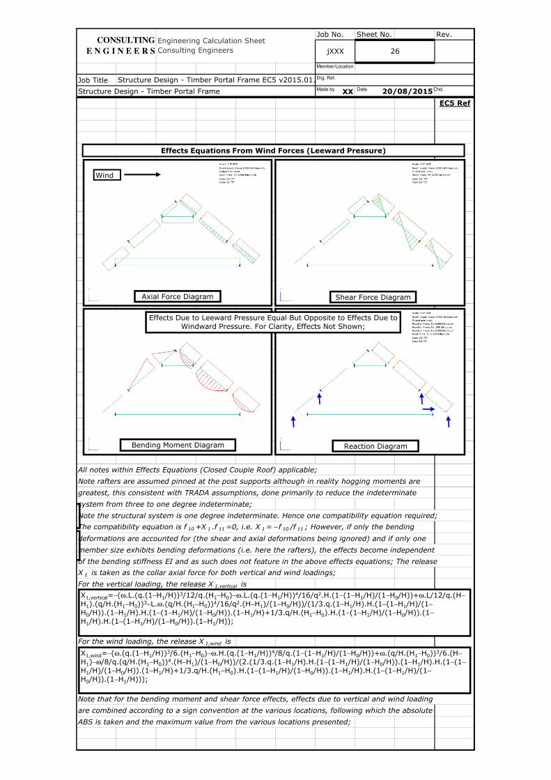
All notes within Effects Equations (Closed Couple Roof) applicable;
Note rafters are assumed pinned at the post supports although in reality hogging moments are
greatest, this consistent with TRADA assumptions, done primarily to reduce the indeterminate
system from three to one degree indeterminate;
Note the structural system is one degree indeterminate. Hence one compatibility equation required;
The compatibility equation is f 10 +X 1 .f 11 =0, i.e. X 1 = − f 10 /f 11 ; However, if only the bending
deformations are accounted for (the shear and axial deformations being ignored) and if only one
member size exhibits bending deformations (i.e. here the rafters), the effects become independent
of the bending stiffness EI and as such does not feature in the above effects equations; The release
X 1 is taken as the collar axial force for both vertical and wind loadings;
For the vertical loading, the release X 1,vertical is
For the wind loading, the release X 1,wind is
Note that for the bending moment and shear force effects, effects due to vertical and wind loading
are combined according to a sign convention at the various locations, following which the absolute
ABS is taken and the maximum value from the various locations presented;
20/08/2015
jXXX 26
Structure Design - Timber Portal Frame EC5 v2015.01.xlsm
Engineering Calculation Sheet Consulting Engineers
Structure Design - Timber Portal Frame
CONSULTING
E N G I N E E R S
X1,vertical=−(ω.L.(q.(1−H1/H))3/12/q.(H1−H0)−ω.L.(q.(1−H1/H))4/16/q2.H.(1−(1−H1/H)/(1−H0/H))+ω.L/12/q.(H−
H1).(q/H.(H1−H0))3−L.ω.(q/H.(H1−H0))4/16/q2.(H−H1)/(1−H0/H))/(1/3.q.(1−H1/H).H.(1−(1−H1/H)/(1−
H0/H)).(1−H1/H).H.(1−(1−H1/H)/(1−H0/H)).(1−H1/H)+1/3.q/H.(H1−H0).H.(1−(1−H1/H)/(1−H0/H)).(1−
H1/H).H.(1−(1−H1/H)/(1−H0/H)).(1−H1/H));
X1,wind=−(ω.(q.(1−H1/H))3/6.(H1−H0)−ω.H.(q.(1−H1/H))4/8/q.(1−(1−H1/H)/(1−H0/H))+ω.(q/H.(H1−H0))3/6.(H−
H1)−ω/8/q.(q/H.(H1−H0))4.(H−H1)/(1−H0/H))/(2.(1/3.q.(1−H1/H).H.(1−(1−H1/H)/(1−H0/H)).(1−H1/H).H.(1−(1−
H1/H)/(1−H0/H)).(1−H1/H)+1/3.q/H.(H1−H0).H.(1−(1−H1/H)/(1−H0/H)).(1−H1/H).H.(1−(1−H1/H)/(1−
H0/H)).(1−H1/H)));
Effects Equations From Wind Forces (Leeward Pressure)
Reaction DiagramBending Moment Diagram
Shear Force DiagramAxial Force Diagram
Wind
Effects Due to Leeward Pressure Equal But Opposite to Effects Due to Windward Pressure. For Clarity, Effects Not Shown;
Made by Date Chd.
Drg. Ref.
Member/Location
Job No. Sheet No. Rev.
Job Title
XX
EC5 Ref
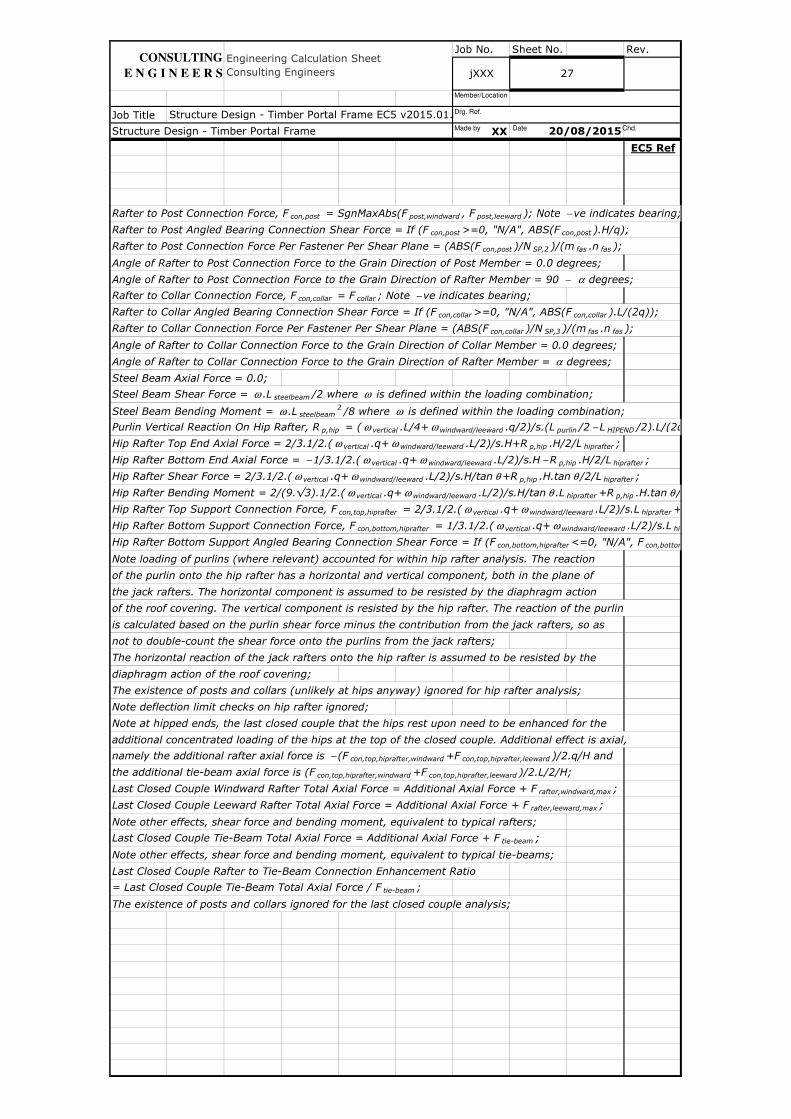
Rafter to Post Connection Force, F con,post = SgnMaxAbs(F post,windward , F post,leeward ); Note − ve indicates bearing;
Rafter to Post Angled Bearing Connection Shear Force = If (F con,post >=0, "N/A", ABS(F con,post ).H/q);
Rafter to Post Connection Force Per Fastener Per Shear Plane = (ABS(F con,post )/N SP,2 )/(m fas .n fas );
Angle of Rafter to Post Connection Force to the Grain Direction of Post Member = 0.0 degrees;
Angle of Rafter to Post Connection Force to the Grain Direction of Rafter Member = 90 − α degrees;
Rafter to Collar Connection Force, F con,collar = F collar ; Note − ve indicates bearing;
Rafter to Collar Angled Bearing Connection Shear Force = If (F con,collar >=0, "N/A", ABS(F con,collar ).L/(2q));
Rafter to Collar Connection Force Per Fastener Per Shear Plane = (ABS(F con,collar )/N SP,3 )/(m fas .n fas );
Angle of Rafter to Collar Connection Force to the Grain Direction of Collar Member = 0.0 degrees;
Angle of Rafter to Collar Connection Force to the Grain Direction of Rafter Member = α degrees;
Steel Beam Axial Force = 0.0;
Steel Beam Shear Force = ω .L steelbeam /2 where ω is defined within the loading combination;
Steel Beam Bending Moment = ω .L steelbeam2 /8 where ω is defined within the loading combination;
Purlin Vertical Reaction On Hip Rafter, R p,hip = ( ω vertical .L/4+ ω windward/leeward .q/2)/s.(L purlin /2 − L HIPEND /2).L/(2q);
Hip Rafter Top End Axial Force = 2/3.1/2.( ω vertical .q+ ω windward/leeward .L/2)/s.H+R p,hip .H/2/L hiprafter ;
Hip Rafter Bottom End Axial Force = − 1/3.1/2.( ω vertical .q+ ω windward/leeward .L/2)/s.H − R p,hip .H/2/L hiprafter ;
Hip Rafter Shear Force = 2/3.1/2.( ω vertical .q+ ω windward/leeward .L/2)/s.H/tan θ +R p,hip .H.tan θ /2/L hiprafter ;
Hip Rafter Bending Moment = 2/(9.√3).1/2.( ω vertical .q+ ω windward/leeward .L/2)/s.H/tan θ .L hiprafter +R p,hip .H.tan θ /4;
Hip Rafter Top Support Connection Force, F con,top,hiprafter = 2/3.1/2.( ω vertical .q+ ω windward/leeward .L/2)/s.L hiprafter +R
Hip Rafter Bottom Support Connection Force, F con,bottom,hiprafter = 1/3.1/2.( ω vertical .q+ ω windward/leeward .L/2)/s.L hiprafter
Hip Rafter Bottom Support Angled Bearing Connection Shear Force = If (F con,bottom,hiprafter <=0, "N/A", F con,bottom,hiprafter
Note loading of purlins (where relevant) accounted for within hip rafter analysis. The reaction
of the purlin onto the hip rafter has a horizontal and vertical component, both in the plane of
the jack rafters. The horizontal component is assumed to be resisted by the diaphragm action
of the roof covering. The vertical component is resisted by the hip rafter. The reaction of the purlin
is calculated based on the purlin shear force minus the contribution from the jack rafters, so as
not to double-count the shear force onto the purlins from the jack rafters;
The horizontal reaction of the jack rafters onto the hip rafter is assumed to be resisted by the
diaphragm action of the roof covering;
The existence of posts and collars (unlikely at hips anyway) ignored for hip rafter analysis;
Note deflection limit checks on hip rafter ignored;
Note at hipped ends, the last closed couple that the hips rest upon need to be enhanced for the
additional concentrated loading of the hips at the top of the closed couple. Additional effect is axial,
namely the additional rafter axial force is − (F con,top,hiprafter,windward +F con,top,hiprafter,leeward )/2.q/H and
the additional tie-beam axial force is (F con,top,hiprafter,windward +F con,top,hiprafter,leeward )/2.L/2/H;
Last Closed Couple Windward Rafter Total Axial Force = Additional Axial Force + F rafter,windward,max ;
Last Closed Couple Leeward Rafter Total Axial Force = Additional Axial Force + F rafter,leeward,max ;
Note other effects, shear force and bending moment, equivalent to typical rafters;
Last Closed Couple Tie-Beam Total Axial Force = Additional Axial Force + F tie-beam ;
Note other effects, shear force and bending moment, equivalent to typical tie-beams;
Last Closed Couple Rafter to Tie-Beam Connection Enhancement Ratio
= Last Closed Couple Tie-Beam Total Axial Force / F tie-beam ;
The existence of posts and collars ignored for the last closed couple analysis;
Structure Design - Timber Portal Frame EC5 v2015.01.xlsm
Structure Design - Timber Portal Frame 20/08/2015
Engineering Calculation Sheet Consulting Engineers jXXX 27
CONSULTING
E N G I N E E R S
Made by Date Chd.
Drg. Ref.
Member/Location
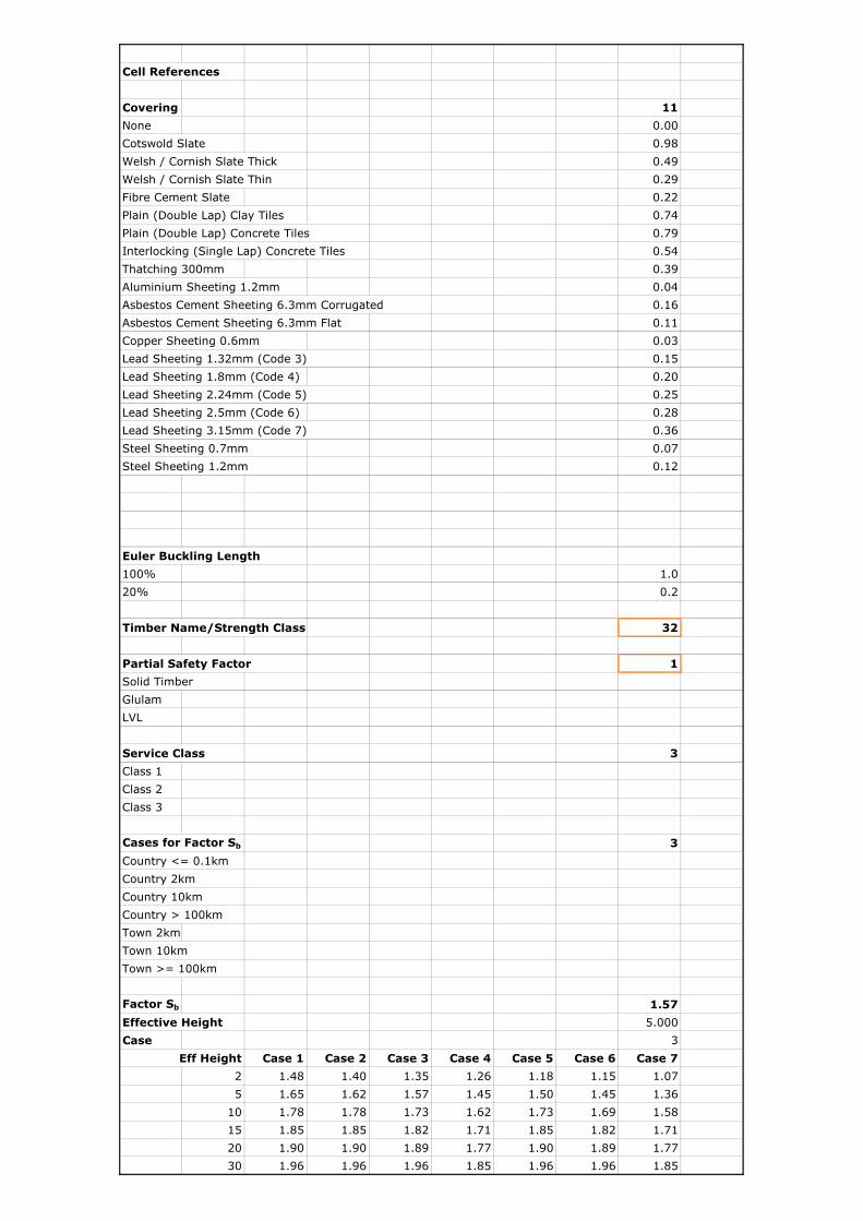
Cell References
Covering 11
None 0.00
Cotswold Slate 0.98
Welsh / Cornish Slate Thick 0.49
Welsh / Cornish Slate Thin 0.29
Fibre Cement Slate 0.22
Plain (Double Lap) Clay Tiles 0.74
Plain (Double Lap) Concrete Tiles 0.79
Interlocking (Single Lap) Concrete Tiles 0.54
Thatching 300mm 0.39
Aluminium Sheeting 1.2mm 0.04
Asbestos Cement Sheeting 6.3mm Corrugated 0.16
Asbestos Cement Sheeting 6.3mm Flat 0.11
Copper Sheeting 0.6mm 0.03
Lead Sheeting 1.32mm (Code 3) 0.15
Lead Sheeting 1.8mm (Code 4) 0.20
Lead Sheeting 2.24mm (Code 5) 0.25
Lead Sheeting 2.5mm (Code 6) 0.28
Lead Sheeting 3.15mm (Code 7) 0.36
Steel Sheeting 0.7mm 0.07
Steel Sheeting 1.2mm 0.12
Euler Buckling Length
100% 1.0
20% 0.2
Timber Name/Strength Class 32
Partial Safety Factor 1
Solid Timber
Glulam
LVL
Service Class 3
Class 1
Class 2
Class 3
Cases for Factor Sb 3
Country <= 0.1km
Country 2km
Country 10km
Country > 100km
Town 2km
Town 10km
Town >= 100km
Factor Sb 1.57
Effective Height 5.000
Case 3
Eff Height Case 1 Case 2 Case 3 Case 4 Case 5 Case 6 Case 7
2 1.48 1.40 1.35 1.26 1.18 1.15 1.07
5 1.65 1.62 1.57 1.45 1.50 1.45 1.36
10 1.78 1.78 1.73 1.62 1.73 1.69 1.58
15 1.85 1.85 1.82 1.71 1.85 1.82 1.71
20 1.90 1.90 1.89 1.77 1.90 1.89 1.77
30 1.96 1.96 1.96 1.85 1.96 1.96 1.85
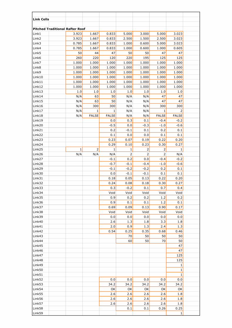
Link Cells
Pitched Traditional Rafter Roof
Link1 3.923 1.667 0.833 5.000 3.000 5.000 3.023
Link2 3.923 1.667 0.833 2.500 1.500 2.500 3.023
Link3 0.785 1.667 0.833 1.000 0.600 5.000 3.023
Link4 0.785 1.667 0.833 1.000 0.600 1.000 0.605
Link5 50 44 47 50 50 47 47
Link6 260 220 120 220 195 125 125
Link7 1.000 1.000 1.000 1.000 1.000 1.000 1.000
Link8 1.000 1.000 1.000 1.000 1.000 1.000 1.000
Link9 1.000 1.000 1.000 1.000 1.000 1.000 1.000
Link10 1.000 1.000 1.000 1.000 1.000 1.000 1.000
Link11 1.000 1.000 1.000 1.000 1.000 1.000 1.000
Link12 1.000 1.000 1.000 1.000 1.000 1.000 1.000
Link13 1.0 1.0 1.0 1.0 1.0 1.0 1.0
Link14 N/A 63 50 N/A N/A 47 47
Link15 N/A 63 50 N/A N/A 47 47
Link16 N/A 300 300 N/A N/A 300 300
Link17 N/A 1 1 N/A N/A 1 2
Link18 N/A FALSE FALSE N/A N/A FALSE FALSE
Link19 0.0 0.3 0.1 -0.4 -0.2
Link20 -0.5 0.0 -0.3 -1.0 -0.6
Link21 0.2 -0.1 0.1 0.2 0.1
Link22 0.1 0.0 0.0 0.1 0.1
Link23 0.23 0.07 0.19 0.22 0.20
Link24 0.29 0.10 0.23 0.30 0.27
Link25 1 2 1 1 2 2 1
Link26 N/A N/A N/A 2 2 2 N/A
Link27 -0.1 0.2 0.0 -0.4 -0.2
Link28 -0.7 -0.1 -0.4 -1.0 -0.6
Link29 -0.1 -0.2 -0.2 0.2 0.1
Link30 0.0 -0.1 -0.1 0.1 0.1
Link31 0.18 0.05 0.13 0.22 0.20
Link32 0.24 0.08 0.18 0.30 0.27
Link33 0.3 -0.2 0.1 0.7 0.4
Link34 Void Void Void Void Void
Link35 0.9 0.2 0.2 1.2 0.2
Link36 0.9 0.1 0.1 1.2 0.1
Link37 0.69 0.09 0.13 0.90 0.17
Link38 Void Void Void Void Void
Link39 0.0 0.0 0.0 0.0 0.0
Link40 2.6 1.3 1.8 3.3 1.8
Link41 2.0 0.9 1.3 2.4 1.3
Link42 0.54 0.25 0.35 0.68 0.46
Link43 70 50 50 50
Link44 60 50 70 50
Link45 47
Link46 47
Link47 125
Link48 125
Link49 1
Link50 1
Link51 1
Link52 0.0 0.0 0.0 0.0 0.0
Link53 34.2 34.2 34.2 34.2 34.2
Link54 OK OK OK OK OK
Link55 2.6 2.6 2.6 2.6 1.8
Link56 2.6 2.6 2.6 2.6 1.8
Link57 2.6 2.6 2.6 2.6 1.8
Link58 0.1 0.1 0.26 0.25
Link59 1
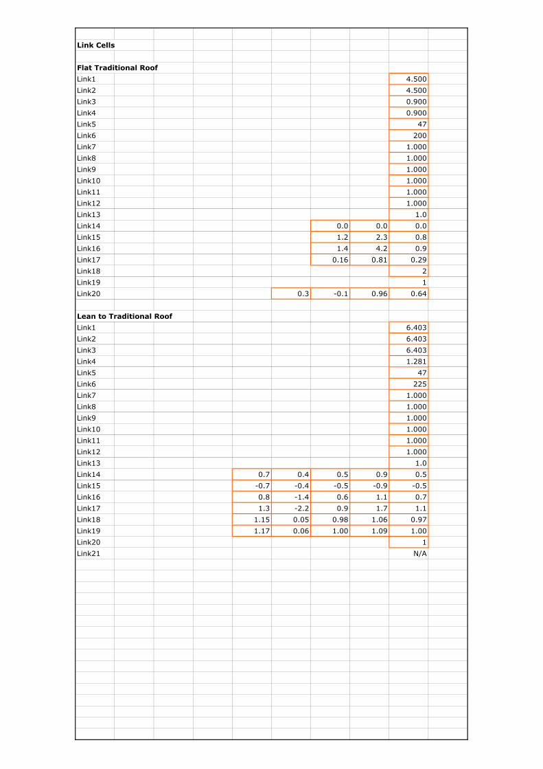
Link Cells
Flat Traditional Roof
Link1 4.500
Link2 4.500
Link3 0.900
Link4 0.900
Link5 47
Link6 200
Link7 1.000
Link8 1.000
Link9 1.000
Link10 1.000
Link11 1.000
Link12 1.000
Link13 1.0
Link14 0.0 0.0 0.0
Link15 1.2 2.3 0.8
Link16 1.4 4.2 0.9
Link17 0.16 0.81 0.29
Link18 2
Link19 1
Link20 0.3 -0.1 0.96 0.64
Lean to Traditional Roof
Link1 6.403
Link2 6.403
Link3 6.403
Link4 1.281
Link5 47
Link6 225
Link7 1.000
Link8 1.000
Link9 1.000
Link10 1.000
Link11 1.000
Link12 1.000
Link13 1.0
Link14 0.7 0.4 0.5 0.9 0.5
Link15 -0.7 -0.4 -0.5 -0.9 -0.5
Link16 0.8 -1.4 0.6 1.1 0.7
Link17 1.3 -2.2 0.9 1.7 1.1
Link18 1.15 0.05 0.98 1.06 0.97
Link19 1.17 0.06 1.00 1.09 1.00
Link20 1
Link21 N/A
Job No. Sheet No. Rev.
Job Title
XX
EC5 Ref
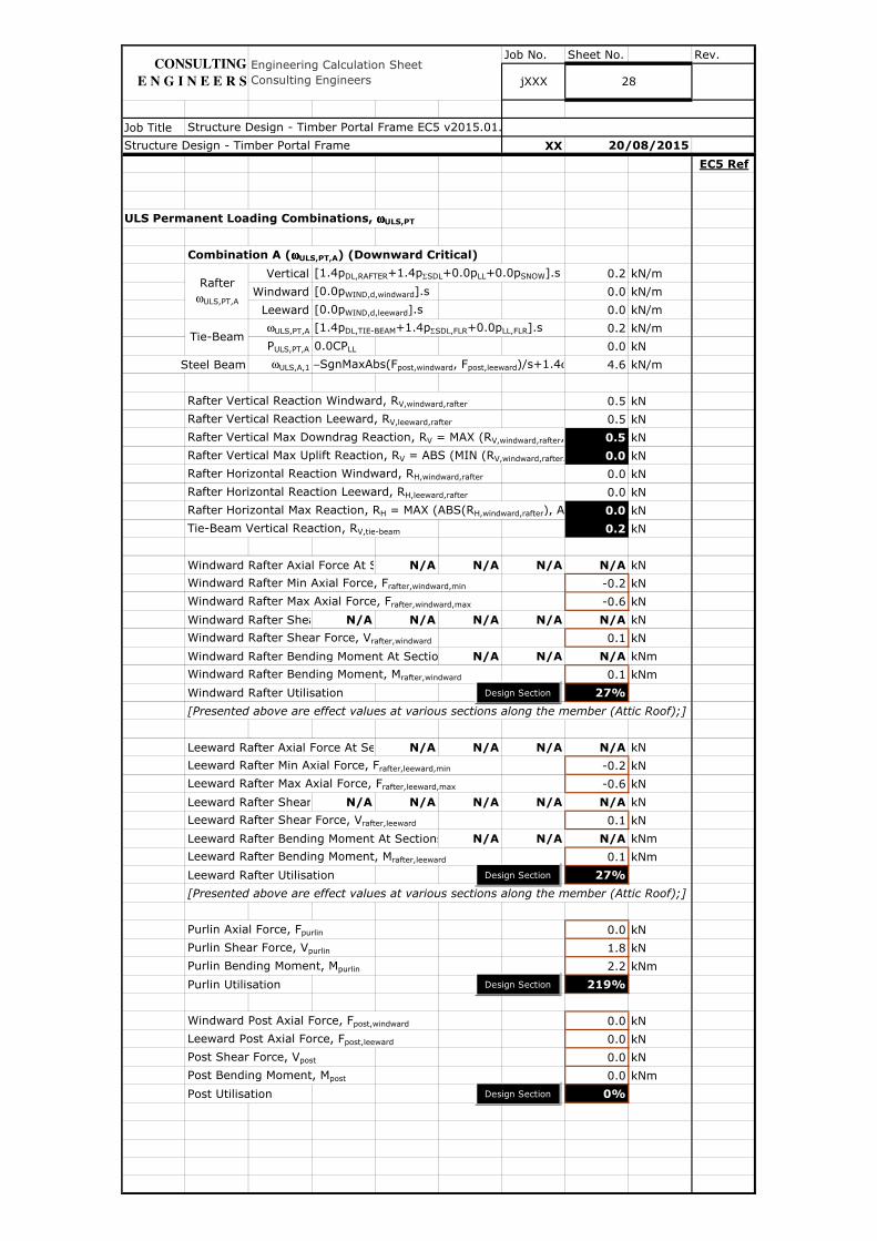
ULS Permanent Loading Combinations, ωωωωULS,PT
Combination A (ωωωωULS,PT,A) (Downward Critical)
Vertical [1.4pDL,RAFTER+1.4pΣSDL+0.0pLL+0.0pSNOW].s 0.2 kN/m
Windward [0.0pWIND,d,windward].s 0.0 kN/m
Leeward [0.0pWIND,d,leeward].s 0.0 kN/m
ωULS,PT,A [1.4pDL,TIE-BEAM+1.4pΣSDL,FLR+0.0pLL,FLR].s 0.2 kN/m
PULS,PT,A 0.0CPLL 0.0 kN
Steel Beam ωULS,A,1 −SgnMaxAbs(Fpost,windward, Fpost,leeward)/s+1.4ω 4.6 kN/m
Rafter Vertical Reaction Windward, RV,windward,rafter 0.5 kN
Rafter Vertical Reaction Leeward, RV,leeward,rafter 0.5 kN
Rafter Vertical Max Downdrag Reaction, RV = MAX (RV,windward,rafter, R 0.5 kN
Rafter Vertical Max Uplift Reaction, RV = ABS (MIN (RV,windward,rafter, R 0.0 kN
Rafter Horizontal Reaction Windward, RH,windward,rafter 0.0 kN
Rafter Horizontal Reaction Leeward, RH,leeward,rafter 0.0 kN
Rafter Horizontal Max Reaction, RH = MAX (ABS(RH,windward,rafter), ABS(R 0.0 kN
Tie-Beam Vertical Reaction, RV,tie-beam 0.2 kN
Windward Rafter Axial Force At SectionsN/A N/A N/A N/A kN
Windward Rafter Min Axial Force, Frafter,windward,min -0.2 kN
Windward Rafter Max Axial Force, Frafter,windward,max -0.6 kN
Windward Rafter Shear Force At SectionsN/A N/A N/A N/A N/A kN
Windward Rafter Shear Force, Vrafter,windward 0.1 kN
Windward Rafter Bending Moment At Sections N/A N/A N/A kNm
Windward Rafter Bending Moment, Mrafter,windward 0.1 kNm
Windward Rafter Utilisation 27%
[Presented above are effect values at various sections along the member (Attic Roof);]
Leeward Rafter Axial Force At SectionsN/A N/A N/A N/A kN
Leeward Rafter Min Axial Force, Frafter,leeward,min -0.2 kN
Leeward Rafter Max Axial Force, Frafter,leeward,max -0.6 kN
Leeward Rafter Shear Force At SectionsN/A N/A N/A N/A N/A kN
Leeward Rafter Shear Force, Vrafter,leeward 0.1 kN
Leeward Rafter Bending Moment At Sections N/A N/A N/A kNm
Leeward Rafter Bending Moment, Mrafter,leeward 0.1 kNm
Leeward Rafter Utilisation 27%
[Presented above are effect values at various sections along the member (Attic Roof);]
Purlin Axial Force, Fpurlin 0.0 kN
Purlin Shear Force, Vpurlin 1.8 kN
Purlin Bending Moment, Mpurlin 2.2 kNm
Purlin Utilisation 219%
Windward Post Axial Force, Fpost,windward 0.0 kN
Leeward Post Axial Force, Fpost,leeward 0.0 kN
Post Shear Force, Vpost 0.0 kN
Post Bending Moment, Mpost 0.0 kNm
Post Utilisation 0%
Rafter ωULS,PT,A
jXXX 28
Tie-Beam
Structure Design - Timber Portal Frame EC5 v2015.01.xlsm
20/08/2015
Engineering Calculation Sheet Consulting Engineers
Structure Design - Timber Portal Frame
CONSULTING
E N G I N E E R S
Design Section
Design Section
Design Section
Design Section

Job No. Sheet No. Rev.
Job Title
XX
EC5 Ref
Collar Axial Force Components (Attic Roof) N/A N/A N/A kN
[Presented above are components due to vertical, windward and leeward loads (Attic Roof);]
Collar Axial Force, Fcollar 0.0 kN
Collar Shear Force, Vcollar 0.0 kN
Collar Bending Moment, Mcollar 0.0 kNm
Collar Utilisation 0%
Tie-Beam Axial Force, Ftie-beam 0.4 kN
Tie-Beam Shear Force, Vtie-beam 0.2 kN
Tie-Beam Bending Moment, Mtie-beam 0.1 kNm
Tie-Beam Utilisation 17%
Binder Axial Force, Fbinder 0.0 kN
Binder Shear Force, Vbinder 1.8 kN
Binder Bending Moment, Mbinder 1.3 kNm
Binder Utilisation 46%
Rafter to Tie-Beam Connection Force, Fcon,tie-beam 0.4 kN
Rafter to Tie-Beam Angled Bearing Connection Shear Force N/A kN
Rafter to Tie-Beam Connection Force Per Fastener Per Shear Plane 0.4 kN
Angle of Rafter to Tie-Beam Connection Force to the Grain Direction Outer Member, 0.0 degrees
Angle of Rafter to Tie-Beam Connection Force to the Grain Direction Inner Member, 34.2 degrees
Check If All Minimum Spacing Requirements Met ? OK
Design Capacity 1 Shear Plane Without Splitting 1.8 kN
Design Capacity 1 Shear Plane With Splitting 1.8 kN
Design Capacity 1 Fastener With Splitting 1.8 kN
Rafter to Tie-Beam Connection Utilisation 23%
Rafter to Post Connection Force, Fcon,post 0.0 kN
Rafter to Post Angled Bearing Connection Shear Force N/A kN
Rafter to Post Connection Force Per Fastener Per Shear Plane 0.0 kN
Angle of Rafter to Post Connection Force to the Grain Direction Outer Member, 0.0 degrees
Angle of Rafter to Post Connection Force to the Grain Direction Inner Member, 55.8 degrees
Check If All Minimum Spacing Requirements Met ? OK
Design Capacity 1 Shear Plane Without Splitting 1.6 kN
Design Capacity 1 Shear Plane With Splitting 1.6 kN
Design Capacity 1 Fastener With Splitting 1.6 kN
Rafter to Post Connection Utilisation 0%
Rafter to Collar Connection Force, Fcon,collar 0.0 kN
Rafter to Collar Angled Bearing Connection Shear Force N/A kN
Rafter to Collar Connection Force Per Fastener Per Shear Plane 0.0 kN
Angle of Rafter to Collar Connection Force to the Grain Direction Outer Member, 0.0 degrees
Angle of Rafter to Collar Connection Force to the Grain Direction Inner Member, 34.2 degrees
Check If All Minimum Spacing Requirements Met ? OK
Design Capacity 1 Shear Plane Without Splitting 1.7 kN
Design Capacity 1 Shear Plane With Splitting 1.7 kN
Design Capacity 1 Fastener With Splitting 1.7 kN
Rafter to Collar Connection Utilisation 0%
Structure Design - Timber Portal Frame 20/08/2015
jXXX 29
Structure Design - Timber Portal Frame EC5 v2015.01.xlsm
Engineering Calculation Sheet Consulting Engineers
CONSULTING
E N G I N E E R S
Design Section
Design Section
Design Connection
Design Section
Design Connection
Design Connection
Made by Date Chd.
Drg. Ref.
Member/Location
Job No. Sheet No. Rev.
Job Title
XX
EC5 Ref
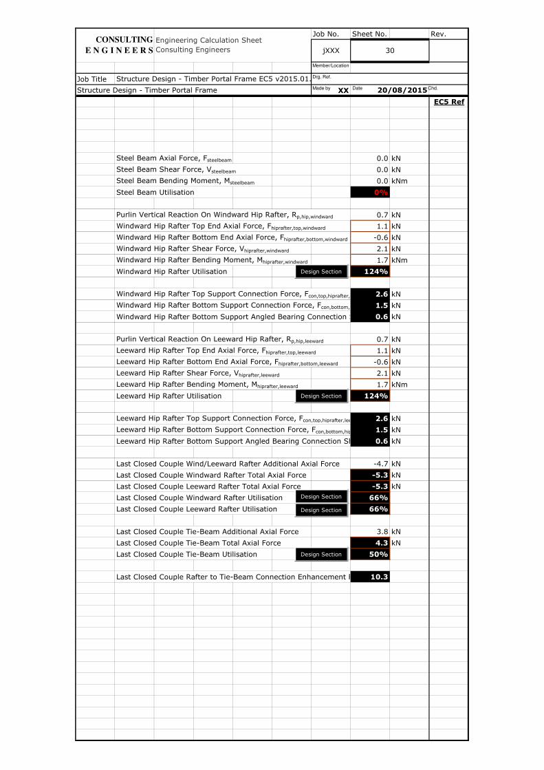
Steel Beam Axial Force, Fsteelbeam 0.0 kN
Steel Beam Shear Force, Vsteelbeam 0.0 kN
Steel Beam Bending Moment, Msteelbeam 0.0 kNm
Steel Beam Utilisation 0%
Purlin Vertical Reaction On Windward Hip Rafter, Rp,hip,windward 0.7 kN
Windward Hip Rafter Top End Axial Force, Fhiprafter,top,windward 1.1 kN
Windward Hip Rafter Bottom End Axial Force, Fhiprafter,bottom,windward -0.6 kN
Windward Hip Rafter Shear Force, Vhiprafter,windward 2.1 kN
Windward Hip Rafter Bending Moment, Mhiprafter,windward 1.7 kNm
Windward Hip Rafter Utilisation 124%
Windward Hip Rafter Top Support Connection Force, Fcon,top,hiprafter,windward 2.6 kN
Windward Hip Rafter Bottom Support Connection Force, Fcon,bottom,hiprafter,windward1.5 kN
Windward Hip Rafter Bottom Support Angled Bearing Connection Shear Force0.6 kN
Purlin Vertical Reaction On Leeward Hip Rafter, Rp,hip,leeward 0.7 kN
Leeward Hip Rafter Top End Axial Force, Fhiprafter,top,leeward 1.1 kN
Leeward Hip Rafter Bottom End Axial Force, Fhiprafter,bottom,leeward -0.6 kN
Leeward Hip Rafter Shear Force, Vhiprafter,leeward 2.1 kN
Leeward Hip Rafter Bending Moment, Mhiprafter,leeward 1.7 kNm
Leeward Hip Rafter Utilisation 124%
Leeward Hip Rafter Top Support Connection Force, Fcon,top,hiprafter,leeward 2.6 kN
Leeward Hip Rafter Bottom Support Connection Force, Fcon,bottom,hiprafter,leeward1.5 kN
Leeward Hip Rafter Bottom Support Angled Bearing Connection Shear Force0.6 kN
Last Closed Couple Wind/Leeward Rafter Additional Axial Force -4.7 kN
Last Closed Couple Windward Rafter Total Axial Force -5.3 kN
Last Closed Couple Leeward Rafter Total Axial Force -5.3 kN
Last Closed Couple Windward Rafter Utilisation 66%
Last Closed Couple Leeward Rafter Utilisation 66%
Last Closed Couple Tie-Beam Additional Axial Force 3.8 kN
Last Closed Couple Tie-Beam Total Axial Force 4.3 kN
Last Closed Couple Tie-Beam Utilisation 50%
Last Closed Couple Rafter to Tie-Beam Connection Enhancement Ratio 10.3
Structure Design - Timber Portal Frame EC5 v2015.01.xlsm
20/08/2015
Engineering Calculation Sheet Consulting Engineers jXXX 30
Structure Design - Timber Portal Frame
CONSULTING
E N G I N E E R S
Design Section
Design Section
Design Section
Design Section
Design Section
Made by Date Chd.
Drg. Ref.
Member/Location
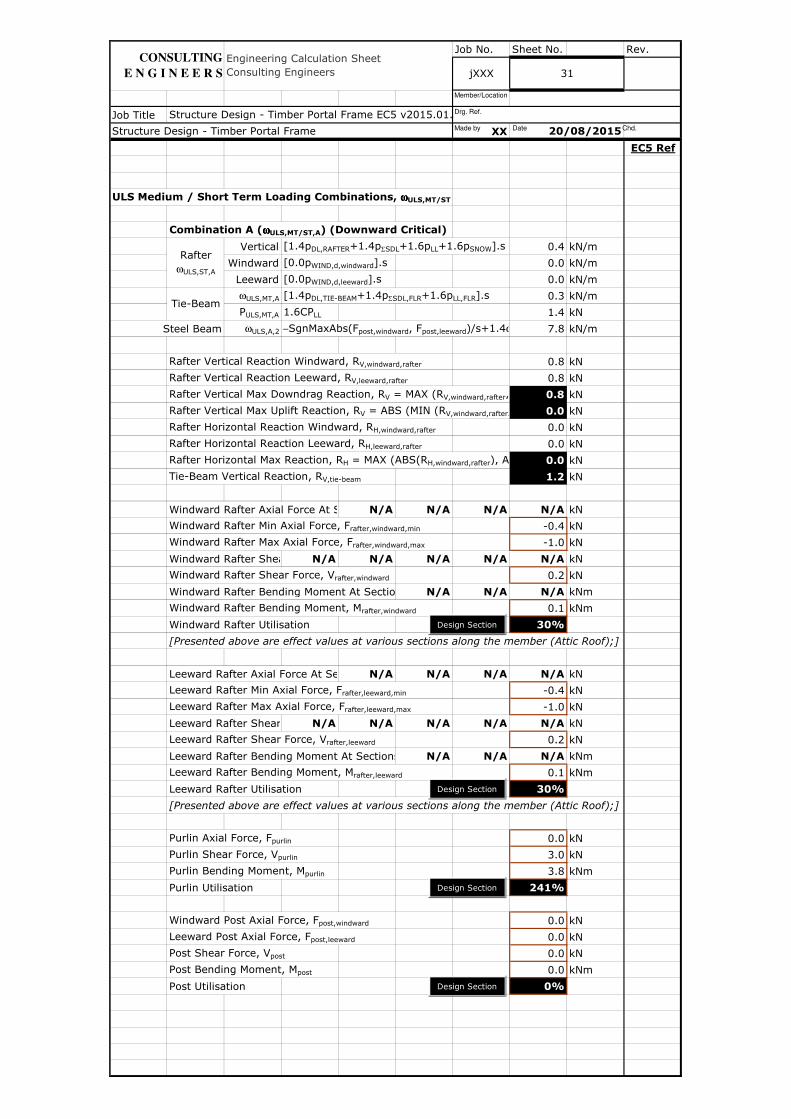
Job No. Sheet No. Rev.
Job Title
XX
EC5 Ref
ULS Medium / Short Term Loading Combinations, ωωωωULS,MT/ST
Combination A (ωωωωULS,MT/ST,A) (Downward Critical)
Vertical [1.4pDL,RAFTER+1.4pΣSDL+1.6pLL+1.6pSNOW].s 0.4 kN/m
Windward [0.0pWIND,d,windward].s 0.0 kN/m
Leeward [0.0pWIND,d,leeward].s 0.0 kN/m
ωULS,MT,A [1.4pDL,TIE-BEAM+1.4pΣSDL,FLR+1.6pLL,FLR].s 0.3 kN/m
PULS,MT,A 1.6CPLL 1.4 kN
Steel Beam ωULS,A,2 −SgnMaxAbs(Fpost,windward, Fpost,leeward)/s+1.4ω 7.8 kN/m
Rafter Vertical Reaction Windward, RV,windward,rafter 0.8 kN
Rafter Vertical Reaction Leeward, RV,leeward,rafter 0.8 kN
Rafter Vertical Max Downdrag Reaction, RV = MAX (RV,windward,rafter, R 0.8 kN
Rafter Vertical Max Uplift Reaction, RV = ABS (MIN (RV,windward,rafter, R 0.0 kN
Rafter Horizontal Reaction Windward, RH,windward,rafter 0.0 kN
Rafter Horizontal Reaction Leeward, RH,leeward,rafter 0.0 kN
Rafter Horizontal Max Reaction, RH = MAX (ABS(RH,windward,rafter), ABS(R 0.0 kN
Tie-Beam Vertical Reaction, RV,tie-beam 1.2 kN
Windward Rafter Axial Force At SectionsN/A N/A N/A N/A kN
Windward Rafter Min Axial Force, Frafter,windward,min -0.4 kN
Windward Rafter Max Axial Force, Frafter,windward,max -1.0 kN
Windward Rafter Shear Force At SectionsN/A N/A N/A N/A N/A kN
Windward Rafter Shear Force, Vrafter,windward 0.2 kN
Windward Rafter Bending Moment At Sections N/A N/A N/A kNm
Windward Rafter Bending Moment, Mrafter,windward 0.1 kNm
Windward Rafter Utilisation 30%
[Presented above are effect values at various sections along the member (Attic Roof);]
Leeward Rafter Axial Force At SectionsN/A N/A N/A N/A kN
Leeward Rafter Min Axial Force, Frafter,leeward,min -0.4 kN
Leeward Rafter Max Axial Force, Frafter,leeward,max -1.0 kN
Leeward Rafter Shear Force At SectionsN/A N/A N/A N/A N/A kN
Leeward Rafter Shear Force, Vrafter,leeward 0.2 kN
Leeward Rafter Bending Moment At Sections N/A N/A N/A kNm
Leeward Rafter Bending Moment, Mrafter,leeward 0.1 kNm
Leeward Rafter Utilisation 30%
[Presented above are effect values at various sections along the member (Attic Roof);]
Purlin Axial Force, Fpurlin 0.0 kN
Purlin Shear Force, Vpurlin 3.0 kN
Purlin Bending Moment, Mpurlin 3.8 kNm
Purlin Utilisation 241%
Windward Post Axial Force, Fpost,windward 0.0 kN
Leeward Post Axial Force, Fpost,leeward 0.0 kN
Post Shear Force, Vpost 0.0 kN
Post Bending Moment, Mpost 0.0 kNm
Post Utilisation 0%
Rafter ωULS,ST,A
Engineering Calculation Sheet Consulting Engineers
Structure Design - Timber Portal Frame
jXXX 31
Structure Design - Timber Portal Frame EC5 v2015.01.xlsm
Tie-Beam
20/08/2015
CONSULTING
E N G I N E E R S
Design Section
Design Section
Design Section
Design Section
Made by Date Chd.
Drg. Ref.
Member/Location

Job No. Sheet No. Rev.
Job Title
XX
EC5 Ref
Collar Axial Force Components (Attic Roof) N/A N/A N/A kN
[Presented above are components due to vertical, windward and leeward loads (Attic Roof);]
Collar Axial Force, Fcollar 0.0 kN
Collar Shear Force, Vcollar 0.0 kN
Collar Bending Moment, Mcollar 0.0 kNm
Collar Utilisation 0%
Tie-Beam Axial Force, Ftie-beam 0.7 kN
Tie-Beam Shear Force, Vtie-beam 1.2 kN
Tie-Beam Bending Moment, Mtie-beam 1.2 kNm
Tie-Beam Utilisation 90%
Binder Axial Force, Fbinder 0.0 kN
Binder Shear Force, Vbinder 3.3 kN
Binder Bending Moment, Mbinder 2.4 kNm
Binder Utilisation 68%
Rafter to Tie-Beam Connection Force, Fcon,tie-beam 0.7 kN
Rafter to Tie-Beam Angled Bearing Connection Shear Force N/A kN
Rafter to Tie-Beam Connection Force Per Fastener Per Shear Plane 0.7 kN
Angle of Rafter to Tie-Beam Connection Force to the Grain Direction Outer Member, 0.0 degrees
Angle of Rafter to Tie-Beam Connection Force to the Grain Direction Inner Member, 34.2 degrees
Check If All Minimum Spacing Requirements Met ? OK
Design Capacity 1 Shear Plane Without Splitting 2.6 kN
Design Capacity 1 Shear Plane With Splitting 2.6 kN
Design Capacity 1 Fastener With Splitting 2.6 kN
Rafter to Tie-Beam Connection Utilisation 27%
Rafter to Post Connection Force, Fcon,post 0.0 kN
Rafter to Post Angled Bearing Connection Shear Force N/A kN
Rafter to Post Connection Force Per Fastener Per Shear Plane 0.0 kN
Angle of Rafter to Post Connection Force to the Grain Direction Outer Member, 0.0 degrees
Angle of Rafter to Post Connection Force to the Grain Direction Inner Member, 55.8 degrees
Check If All Minimum Spacing Requirements Met ? OK
Design Capacity 1 Shear Plane Without Splitting 2.5 kN
Design Capacity 1 Shear Plane With Splitting 2.5 kN
Design Capacity 1 Fastener With Splitting 2.5 kN
Rafter to Post Connection Utilisation 0%
Rafter to Collar Connection Force, Fcon,collar 0.0 kN
Rafter to Collar Angled Bearing Connection Shear Force N/A kN
Rafter to Collar Connection Force Per Fastener Per Shear Plane 0.0 kN
Angle of Rafter to Collar Connection Force to the Grain Direction Outer Member, 0.0 degrees
Angle of Rafter to Collar Connection Force to the Grain Direction Inner Member, 34.2 degrees
Check If All Minimum Spacing Requirements Met ? OK
Design Capacity 1 Shear Plane Without Splitting 2.5 kN
Design Capacity 1 Shear Plane With Splitting 2.5 kN
Design Capacity 1 Fastener With Splitting 2.5 kN
Rafter to Collar Connection Utilisation 0%
Engineering Calculation Sheet Consulting Engineers jXXX 32
Structure Design - Timber Portal Frame EC5 v2015.01.xlsm
Structure Design - Timber Portal Frame 20/08/2015
CONSULTING
E N G I N E E R S
Design Section
Design Section
Design Connection
Design Section
Design Connection
Design Connection
Made by Date Chd.
Drg. Ref.
Member/Location

Job No. Sheet No. Rev.
Job Title
XX
EC5 Ref
Steel Beam Axial Force, Fsteelbeam 0.0 kN
Steel Beam Shear Force, Vsteelbeam 0.0 kN
Steel Beam Bending Moment, Msteelbeam 0.0 kNm
Steel Beam Utilisation 0%
Purlin Vertical Reaction On Windward Hip Rafter, Rp,hip,windward 1.3 kN
Windward Hip Rafter Top End Axial Force, Fhiprafter,top,windward 1.9 kN
Windward Hip Rafter Bottom End Axial Force, Fhiprafter,bottom,windward -1.1 kN
Windward Hip Rafter Shear Force, Vhiprafter,windward 3.6 kN
Windward Hip Rafter Bending Moment, Mhiprafter,windward 2.9 kNm
Windward Hip Rafter Utilisation 137%
Windward Hip Rafter Top Support Connection Force, Fcon,top,hiprafter,windward 4.5 kN
Windward Hip Rafter Bottom Support Connection Force, Fcon,bottom,hiprafter,windward2.5 kN
Windward Hip Rafter Bottom Support Angled Bearing Connection Shear Force1.1 kN
Purlin Vertical Reaction On Leeward Hip Rafter, Rp,hip,leeward 1.3 kN
Leeward Hip Rafter Top End Axial Force, Fhiprafter,top,leeward 1.9 kN
Leeward Hip Rafter Bottom End Axial Force, Fhiprafter,bottom,leeward -1.1 kN
Leeward Hip Rafter Shear Force, Vhiprafter,leeward 3.6 kN
Leeward Hip Rafter Bending Moment, Mhiprafter,leeward 2.9 kNm
Leeward Hip Rafter Utilisation 137%
Leeward Hip Rafter Top Support Connection Force, Fcon,top,hiprafter,leeward 4.5 kN
Leeward Hip Rafter Bottom Support Connection Force, Fcon,bottom,hiprafter,leeward2.5 kN
Leeward Hip Rafter Bottom Support Angled Bearing Connection Shear Force1.1 kN
Last Closed Couple Wind/Leeward Rafter Additional Axial Force -7.9 kN
Last Closed Couple Windward Rafter Total Axial Force -8.9 kN
Last Closed Couple Leeward Rafter Total Axial Force -8.9 kN
Last Closed Couple Windward Rafter Utilisation 73%
Last Closed Couple Leeward Rafter Utilisation 73%
Last Closed Couple Tie-Beam Additional Axial Force 6.6 kN
Last Closed Couple Tie-Beam Total Axial Force 7.3 kN
Last Closed Couple Tie-Beam Utilisation 114%
Last Closed Couple Rafter to Tie-Beam Connection Enhancement Ratio 10.3
Engineering Calculation Sheet Consulting Engineers jXXX 33
Structure Design - Timber Portal Frame EC5 v2015.01.xlsm
Structure Design - Timber Portal Frame 20/08/2015
CONSULTING
E N G I N E E R S
Design Section
Design Section
Design Section
Design Section
Design Section
Made by Date Chd.
Drg. Ref.
Member/Location
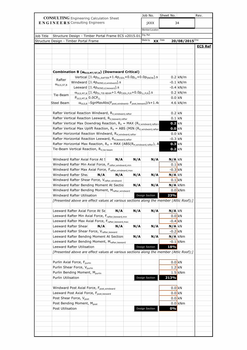
Job No. Sheet No. Rev.
Job Title
XX
EC5 Ref
Combination B (ωωωωULS,MT/ST,B) (Downward Critical)
Vertical [1.4pDL,RAFTER+1.4pΣSDL+0.0pLL+0.0pSNOW].s 0.2 kN/m
Windward [1.4pWIND,d,windward].s -0.1 kN/m
Leeward [1.4pWIND,d,leeward].s -0.4 kN/m
ωULS,MT,B [1.4pDL,TIE-BEAM+1.4pΣSDL,FLR+0.0pLL,FLR].s 0.2 kN/m
PULS,MT,B 0.0CPLL 0.0 kN
Steel Beam ωULS,B −SgnMaxAbs(Fpost,windward, Fpost,leeward)/s+1.4ω 4.6 kN/m
Rafter Vertical Reaction Windward, RV,windward,rafter 0.2 kN
Rafter Vertical Reaction Leeward, RV,leeward,rafter 0.1 kN
Rafter Vertical Max Downdrag Reaction, RV = MAX (RV,windward,rafter, R 0.2 kN
Rafter Vertical Max Uplift Reaction, RV = ABS (MIN (RV,windward,rafter, R 0.0 kN
Rafter Horizontal Reaction Windward, RH,windward,rafter 0.0 kN
Rafter Horizontal Reaction Leeward, RH,leeward,rafter -0.3 kN
Rafter Horizontal Max Reaction, RH = MAX (ABS(RH,windward,rafter), ABS(R 0.3 kN
Tie-Beam Vertical Reaction, RV,tie-beam 0.2 kN
Windward Rafter Axial Force At SectionsN/A N/A N/A N/A kN
Windward Rafter Min Axial Force, Frafter,windward,min 0.1 kN
Windward Rafter Max Axial Force, Frafter,windward,max -0.3 kN
Windward Rafter Shear Force At SectionsN/A N/A N/A N/A N/A kN
Windward Rafter Shear Force, Vrafter,windward 0.1 kN
Windward Rafter Bending Moment At Sections N/A N/A N/A kNm
Windward Rafter Bending Moment, Mrafter,windward 0.0 kNm
Windward Rafter Utilisation 23%
[Presented above are effect values at various sections along the member (Attic Roof);]
Leeward Rafter Axial Force At SectionsN/A N/A N/A N/A kN
Leeward Rafter Min Axial Force, Frafter,leeward,min 0.0 kN
Leeward Rafter Max Axial Force, Frafter,leeward,max -0.4 kN
Leeward Rafter Shear Force At SectionsN/A N/A N/A N/A N/A kN
Leeward Rafter Shear Force, Vrafter,leeward -0.2 kN
Leeward Rafter Bending Moment At Sections N/A N/A N/A kNm
Leeward Rafter Bending Moment, Mrafter,leeward -0.1 kNm
Leeward Rafter Utilisation 18%
[Presented above are effect values at various sections along the member (Attic Roof);]
Purlin Axial Force, Fpurlin 0.0 kN
Purlin Shear Force, Vpurlin 1.2 kN
Purlin Bending Moment, Mpurlin 1.5 kNm
Purlin Utilisation 213%
Windward Post Axial Force, Fpost,windward 0.0 kN
Leeward Post Axial Force, Fpost,leeward 0.0 kN
Post Shear Force, Vpost 0.0 kN
Post Bending Moment, Mpost 0.0 kNm
Post Utilisation 0%
20/08/2015Structure Design - Timber Portal Frame
Engineering Calculation Sheet Consulting Engineers
Structure Design - Timber Portal Frame EC5 v2015.01.xlsm
jXXX
Rafter ωULS,ST,B
Tie-Beam
34
CONSULTING
E N G I N E E R S
Design Section
Design Section
Design Section
Design Section
Made by Date Chd.
Drg. Ref.
Member/Location

Job No. Sheet No. Rev.
Job Title
XX
EC5 Ref
Collar Axial Force Components (Attic Roof) N/A N/A N/A kN
[Presented above are components due to vertical, windward and leeward loads (Attic Roof);]
Collar Axial Force, Fcollar 0.0 kN
Collar Shear Force, Vcollar 0.0 kN
Collar Bending Moment, Mcollar 0.0 kNm
Collar Utilisation 0%
Tie-Beam Axial Force, Ftie-beam 0.1 kN
Tie-Beam Shear Force, Vtie-beam 0.2 kN
Tie-Beam Bending Moment, Mtie-beam 0.1 kNm
Tie-Beam Utilisation 13%
Binder Axial Force, Fbinder 0.0 kN
Binder Shear Force, Vbinder 1.8 kN
Binder Bending Moment, Mbinder 1.3 kNm
Binder Utilisation 35%
Rafter to Tie-Beam Connection Force, Fcon,tie-beam 0.1 kN
Rafter to Tie-Beam Angled Bearing Connection Shear Force N/A kN
Rafter to Tie-Beam Connection Force Per Fastener Per Shear Plane 0.1 kN
Angle of Rafter to Tie-Beam Connection Force to the Grain Direction Outer Member, 0.0 degrees
Angle of Rafter to Tie-Beam Connection Force to the Grain Direction Inner Member, 34.2 degrees
Check If All Minimum Spacing Requirements Met ? OK
Design Capacity 1 Shear Plane Without Splitting 2.6 kN
Design Capacity 1 Shear Plane With Splitting 2.6 kN
Design Capacity 1 Fastener With Splitting 2.6 kN
Rafter to Tie-Beam Connection Utilisation 4%
Rafter to Post Connection Force, Fcon,post 0.0 kN
Rafter to Post Angled Bearing Connection Shear Force N/A kN
Rafter to Post Connection Force Per Fastener Per Shear Plane 0.0 kN
Angle of Rafter to Post Connection Force to the Grain Direction Outer Member, 0.0 degrees
Angle of Rafter to Post Connection Force to the Grain Direction Inner Member, 55.8 degrees
Check If All Minimum Spacing Requirements Met ? OK
Design Capacity 1 Shear Plane Without Splitting 2.5 kN
Design Capacity 1 Shear Plane With Splitting 2.5 kN
Design Capacity 1 Fastener With Splitting 2.5 kN
Rafter to Post Connection Utilisation 0%
Rafter to Collar Connection Force, Fcon,collar 0.0 kN
Rafter to Collar Angled Bearing Connection Shear Force N/A kN
Rafter to Collar Connection Force Per Fastener Per Shear Plane 0.0 kN
Angle of Rafter to Collar Connection Force to the Grain Direction Outer Member, 0.0 degrees
Angle of Rafter to Collar Connection Force to the Grain Direction Inner Member, 34.2 degrees
Check If All Minimum Spacing Requirements Met ? OK
Design Capacity 1 Shear Plane Without Splitting 2.5 kN
Design Capacity 1 Shear Plane With Splitting 2.5 kN
Design Capacity 1 Fastener With Splitting 2.5 kN
Rafter to Collar Connection Utilisation 0%
Engineering Calculation Sheet Consulting Engineers jXXX 35
Structure Design - Timber Portal Frame EC5 v2015.01.xlsm
Structure Design - Timber Portal Frame 20/08/2015
CONSULTING
E N G I N E E R S
Design Section
Design Section
Design Connection
Design Section
Design Connection
Design Connection
Made by Date Chd.
Drg. Ref.
Member/Location

Job No. Sheet No. Rev.
Job Title
XX
EC5 Ref
Steel Beam Axial Force, Fsteelbeam 0.0 kN
Steel Beam Shear Force, Vsteelbeam 0.0 kN
Steel Beam Bending Moment, Msteelbeam 0.0 kNm
Steel Beam Utilisation 0%
Purlin Vertical Reaction On Windward Hip Rafter, Rp,hip,windward 0.5 kN
Windward Hip Rafter Top End Axial Force, Fhiprafter,top,windward 0.9 kN
Windward Hip Rafter Bottom End Axial Force, Fhiprafter,bottom,windward -0.5 kN
Windward Hip Rafter Shear Force, Vhiprafter,windward 1.7 kN
Windward Hip Rafter Bending Moment, Mhiprafter,windward 1.3 kNm
Windward Hip Rafter Utilisation 110%
Windward Hip Rafter Top Support Connection Force, Fcon,top,hiprafter,windward 2.0 kN
Windward Hip Rafter Bottom Support Connection Force, Fcon,bottom,hiprafter,windward1.1 kN
Windward Hip Rafter Bottom Support Angled Bearing Connection Shear Force0.5 kN
Purlin Vertical Reaction On Leeward Hip Rafter, Rp,hip,leeward -0.8 kN
Leeward Hip Rafter Top End Axial Force, Fhiprafter,top,leeward -0.6 kN
Leeward Hip Rafter Bottom End Axial Force, Fhiprafter,bottom,leeward 0.4 kN
Leeward Hip Rafter Shear Force, Vhiprafter,leeward -1.0 kN
Leeward Hip Rafter Bending Moment, Mhiprafter,leeward -0.9 kNm
Leeward Hip Rafter Utilisation 78%
Leeward Hip Rafter Top Support Connection Force, Fcon,top,hiprafter,leeward -1.5 kN
Leeward Hip Rafter Bottom Support Connection Force, Fcon,bottom,hiprafter,leeward-0.9 kN
Leeward Hip Rafter Bottom Support Angled Bearing Connection Shear ForceN/A kN
Last Closed Couple Wind/Leeward Rafter Additional Axial Force -0.5 kN
Last Closed Couple Windward Rafter Total Axial Force -0.8 kN
Last Closed Couple Leeward Rafter Total Axial Force -0.9 kN
Last Closed Couple Windward Rafter Utilisation 52%
Last Closed Couple Leeward Rafter Utilisation 48%
Last Closed Couple Tie-Beam Additional Axial Force 0.4 kN
Last Closed Couple Tie-Beam Total Axial Force 0.5 kN
Last Closed Couple Tie-Beam Utilisation 41%
Last Closed Couple Rafter to Tie-Beam Connection Enhancement Ratio 5.1
36
Structure Design - Timber Portal Frame 20/08/2015
Structure Design - Timber Portal Frame EC5 v2015.01.xlsm
Engineering Calculation Sheet Consulting Engineers jXXX
CONSULTING
E N G I N E E R S
Design Section
Design Section
Design Section
Design Section
Design Section
Made by Date Chd.
Drg. Ref.
Member/Location

Job No. Sheet No. Rev.
Job Title
XX
EC5 Ref
Combination C (ωωωωULS,MT/ST,C) (Upward Critical)
Vertical [1.0pDL,RAFTER+1.0pΣSDL+0.0pLL+0.0pSNOW].s 0.2 kN/m
Windward [1.4pWIND,u,windward].s -0.3 kN/m
Leeward [1.4pWIND,u,leeward].s -0.4 kN/m
ωULS,MT,C [1.0pDL,TIE-BEAM+1.0pΣSDL,FLR+0.0pLL,FLR].s 0.1 kN/m
PULS,MT,C 0.0CPLL 0.0 kN
Steel Beam ωULS,C −SgnMaxAbs(Fpost,windward, Fpost,leeward)/s+1.0ω 3.3 kN/m
Rafter Vertical Reaction Windward, RV,windward,rafter -0.1 kN
Rafter Vertical Reaction Leeward, RV,leeward,rafter -0.1 kN
Rafter Vertical Max Downdrag Reaction, RV = MAX (RV,windward,rafter, R 0.0 kN
Rafter Vertical Max Uplift Reaction, RV = ABS (MIN (RV,windward,rafter, R 0.1 kN
Rafter Horizontal Reaction Windward, RH,windward,rafter -0.2 kN
Rafter Horizontal Reaction Leeward, RH,leeward,rafter -0.3 kN
Rafter Horizontal Max Reaction, RH = MAX (ABS(RH,windward,rafter), ABS(R 0.3 kN
Tie-Beam Vertical Reaction, RV,tie-beam 0.2 kN
Windward Rafter Axial Force At SectionsN/A N/A N/A N/A kN
Windward Rafter Min Axial Force, Frafter,windward,min 0.3 kN
Windward Rafter Max Axial Force, Frafter,windward,max 0.0 kN
Windward Rafter Shear Force At SectionsN/A N/A N/A N/A N/A kN
Windward Rafter Shear Force, Vrafter,windward -0.1 kN
Windward Rafter Bending Moment At Sections N/A N/A N/A kNm
Windward Rafter Bending Moment, Mrafter,windward 0.0 kNm
Windward Rafter Utilisation 10%
[Presented above are effect values at various sections along the member (Attic Roof);]
Leeward Rafter Axial Force At SectionsN/A N/A N/A N/A kN
Leeward Rafter Min Axial Force, Frafter,leeward,min 0.2 kN
Leeward Rafter Max Axial Force, Frafter,leeward,max -0.1 kN
Leeward Rafter Shear Force At SectionsN/A N/A N/A N/A N/A kN
Leeward Rafter Shear Force, Vrafter,leeward -0.2 kN
Leeward Rafter Bending Moment At Sections N/A N/A N/A kNm
Leeward Rafter Bending Moment, Mrafter,leeward -0.1 kNm
Leeward Rafter Utilisation 8%
[Presented above are effect values at various sections along the member (Attic Roof);]
Purlin Axial Force, Fpurlin 0.0 kN
Purlin Shear Force, Vpurlin -1.5 kN
Purlin Bending Moment, Mpurlin -1.9 kNm
Purlin Utilisation 75%
Windward Post Axial Force, Fpost,windward 0.0 kN
Leeward Post Axial Force, Fpost,leeward 0.0 kN
Post Shear Force, Vpost 0.0 kN
Post Bending Moment, Mpost 0.0 kNm
Post Utilisation 0%
37
Engineering Calculation Sheet Consulting Engineers jXXX
Structure Design - Timber Portal Frame EC5 v2015.01.xlsm
Structure Design - Timber Portal Frame 20/08/2015
Tie-Beam
Rafter ωULS,ST,C
CONSULTING
E N G I N E E R S
Design Section
Design Section
Design Section
Design Section
Made by Date Chd.
Drg. Ref.
Member/Location
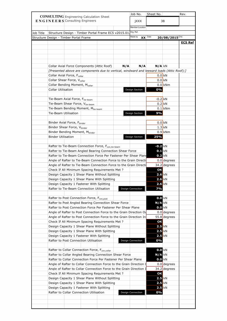
Job No. Sheet No. Rev.
Job Title
XX
EC5 Ref
Collar Axial Force Components (Attic Roof) N/A N/A N/A kN
[Presented above are components due to vertical, windward and leeward loads (Attic Roof);]
Collar Axial Force, Fcollar 0.0 kN
Collar Shear Force, Vcollar 0.0 kN
Collar Bending Moment, Mcollar 0.0 kNm
Collar Utilisation 0%
Tie-Beam Axial Force, Ftie-beam -0.2 kN
Tie-Beam Shear Force, Vtie-beam 0.2 kN
Tie-Beam Bending Moment, Mtie-beam 0.1 kNm
Tie-Beam Utilisation 9%
Binder Axial Force, Fbinder 0.0 kN
Binder Shear Force, Vbinder 1.3 kN
Binder Bending Moment, Mbinder 0.9 kNm
Binder Utilisation 25%
Rafter to Tie-Beam Connection Force, Fcon,tie-beam -0.2 kN
Rafter to Tie-Beam Angled Bearing Connection Shear Force 0.1 kN
Rafter to Tie-Beam Connection Force Per Fastener Per Shear Plane 0.2 kN
Angle of Rafter to Tie-Beam Connection Force to the Grain Direction Outer Member, 0.0 degrees
Angle of Rafter to Tie-Beam Connection Force to the Grain Direction Inner Member, 34.2 degrees
Check If All Minimum Spacing Requirements Met ? OK
Design Capacity 1 Shear Plane Without Splitting 2.6 kN
Design Capacity 1 Shear Plane With Splitting 2.6 kN
Design Capacity 1 Fastener With Splitting 2.6 kN
Rafter to Tie-Beam Connection Utilisation 7%
Rafter to Post Connection Force, Fcon,post 0.0 kN
Rafter to Post Angled Bearing Connection Shear Force N/A kN
Rafter to Post Connection Force Per Fastener Per Shear Plane 0.0 kN
Angle of Rafter to Post Connection Force to the Grain Direction Outer Member, 0.0 degrees
Angle of Rafter to Post Connection Force to the Grain Direction Inner Member, 55.8 degrees
Check If All Minimum Spacing Requirements Met ? OK
Design Capacity 1 Shear Plane Without Splitting 2.5 kN
Design Capacity 1 Shear Plane With Splitting 2.5 kN
Design Capacity 1 Fastener With Splitting 2.5 kN
Rafter to Post Connection Utilisation 0%
Rafter to Collar Connection Force, Fcon,collar 0.0 kN
Rafter to Collar Angled Bearing Connection Shear Force N/A kN
Rafter to Collar Connection Force Per Fastener Per Shear Plane 0.0 kN
Angle of Rafter to Collar Connection Force to the Grain Direction Outer Member, 0.0 degrees
Angle of Rafter to Collar Connection Force to the Grain Direction Inner Member, 34.2 degrees
Check If All Minimum Spacing Requirements Met ? OK
Design Capacity 1 Shear Plane Without Splitting 2.5 kN
Design Capacity 1 Shear Plane With Splitting 2.5 kN
Design Capacity 1 Fastener With Splitting 2.5 kN
Rafter to Collar Connection Utilisation 0%
Structure Design - Timber Portal Frame EC5 v2015.01.xlsm
Structure Design - Timber Portal Frame 20/08/2015
jXXX 38
Engineering Calculation Sheet Consulting Engineers
CONSULTING
E N G I N E E R S
Design Section
Design Section
Design Connection
Design Section
Design Connection
Design Connection
Made by Date Chd.
Drg. Ref.
Member/Location

Job No. Sheet No. Rev.
Job Title
XX
EC5 Ref
Steel Beam Axial Force, Fsteelbeam 0.0 kN
Steel Beam Shear Force, Vsteelbeam 0.0 kN
Steel Beam Bending Moment, Msteelbeam 0.0 kNm
Steel Beam Utilisation 0%
Purlin Vertical Reaction On Windward Hip Rafter, Rp,hip,windward -0.6 kN
Windward Hip Rafter Top End Axial Force, Fhiprafter,top,windward -0.5 kN
Windward Hip Rafter Bottom End Axial Force, Fhiprafter,bottom,windward 0.3 kN
Windward Hip Rafter Shear Force, Vhiprafter,windward -0.8 kN
Windward Hip Rafter Bending Moment, Mhiprafter,windward -0.7 kNm
Windward Hip Rafter Utilisation 47%
Windward Hip Rafter Top Support Connection Force, Fcon,top,hiprafter,windward-1.1 kN
Windward Hip Rafter Bottom Support Connection Force, Fcon,bottom,hiprafter,windward-0.7 kN
Windward Hip Rafter Bottom Support Angled Bearing Connection Shear ForceN/A kN
Purlin Vertical Reaction On Leeward Hip Rafter, Rp,hip,leeward -1.1 kN
Leeward Hip Rafter Top End Axial Force, Fhiprafter,top,leeward -1.0 kN
Leeward Hip Rafter Bottom End Axial Force, Fhiprafter,bottom,leeward 0.6 kN
Leeward Hip Rafter Shear Force, Vhiprafter,leeward -1.6 kN
Leeward Hip Rafter Bending Moment, Mhiprafter,leeward -1.4 kNm
Leeward Hip Rafter Utilisation 37%
Leeward Hip Rafter Top Support Connection Force, Fcon,top,hiprafter,leeward -2.2 kN
Leeward Hip Rafter Bottom Support Connection Force, Fcon,bottom,hiprafter,leeward-1.4 kN
Leeward Hip Rafter Bottom Support Angled Bearing Connection Shear ForceN/A kN
Last Closed Couple Wind/Leeward Rafter Additional Axial Force 2.9 kN
Last Closed Couple Windward Rafter Total Axial Force 2.9 kN
Last Closed Couple Leeward Rafter Total Axial Force 2.9 kN
Last Closed Couple Windward Rafter Utilisation 23%
Last Closed Couple Leeward Rafter Utilisation 21%
Last Closed Couple Tie-Beam Additional Axial Force -2.4 kN
Last Closed Couple Tie-Beam Total Axial Force -2.6 kN
Last Closed Couple Tie-Beam Utilisation 20%
Last Closed Couple Rafter to Tie-Beam Connection Enhancement Ratio 15.1
Structure Design - Timber Portal Frame EC5 v2015.01.xlsm
Structure Design - Timber Portal Frame 20/08/2015
Engineering Calculation Sheet Consulting Engineers jXXX 39
CONSULTING
E N G I N E E R S
Design Section
Design Section
Design Section
Design Section
Design Section
Made by Date Chd.
Drg. Ref.
Member/Location

Job No. Sheet No. Rev.
Job Title
XX
EC5 Ref
Combination D (ωωωωULS,MT/ST,D) (Downward Critical)
Vertical [1.2pDL,RAFTER+1.2pΣSDL+1.2pLL+1.2pSNOW].s 0.3 kN/m
Windward [1.2pWIND,d,windward].s 0.0 kN/m
Leeward [1.2pWIND,d,leeward].s -0.3 kN/m
ωULS,MT,D [1.2pDL,TIE-BEAM+1.2pΣSDL,FLR+1.2pLL,FLR].s 0.3 kN/m
PULS,MT,D 1.2CPLL 1.1 kN
Steel Beam ωULS,D −SgnMaxAbs(Fpost,windward, Fpost,leeward)/s+1.2ω 6.4 kN/m
Rafter Vertical Reaction Windward, RV,windward,rafter 0.4 kN
Rafter Vertical Reaction Leeward, RV,leeward,rafter 0.3 kN
Rafter Vertical Max Downdrag Reaction, RV = MAX (RV,windward,rafter, R 0.4 kN
Rafter Vertical Max Uplift Reaction, RV = ABS (MIN (RV,windward,rafter, R 0.0 kN
Rafter Horizontal Reaction Windward, RH,windward,rafter 0.0 kN
Rafter Horizontal Reaction Leeward, RH,leeward,rafter -0.3 kN
Rafter Horizontal Max Reaction, RH = MAX (ABS(RH,windward,rafter), ABS(R 0.3 kN
Tie-Beam Vertical Reaction, RV,tie-beam 0.9 kN
Windward Rafter Axial Force At SectionsN/A N/A N/A N/A kN
Windward Rafter Min Axial Force, Frafter,windward,min 0.0 kN
Windward Rafter Max Axial Force, Frafter,windward,max -0.5 kN
Windward Rafter Shear Force At SectionsN/A N/A N/A N/A N/A kN
Windward Rafter Shear Force, Vrafter,windward 0.2 kN
Windward Rafter Bending Moment At Sections N/A N/A N/A kNm
Windward Rafter Bending Moment, Mrafter,windward 0.1 kNm
Windward Rafter Utilisation 29%
[Presented above are effect values at various sections along the member (Attic Roof);]
Leeward Rafter Axial Force At SectionsN/A N/A N/A N/A kN
Leeward Rafter Min Axial Force, Frafter,leeward,min -0.1 kN
Leeward Rafter Max Axial Force, Frafter,leeward,max -0.7 kN
Leeward Rafter Shear Force At SectionsN/A N/A N/A N/A N/A kN
Leeward Rafter Shear Force, Vrafter,leeward -0.1 kN
Leeward Rafter Bending Moment At Sections N/A N/A N/A kNm
Leeward Rafter Bending Moment, Mrafter,leeward 0.0 kNm
Leeward Rafter Utilisation 24%
[Presented above are effect values at various sections along the member (Attic Roof);]
Purlin Axial Force, Fpurlin 0.0 kN
Purlin Shear Force, Vpurlin 2.0 kN
Purlin Bending Moment, Mpurlin 2.5 kNm
Purlin Utilisation 254%
Windward Post Axial Force, Fpost,windward 0.0 kN
Leeward Post Axial Force, Fpost,leeward 0.0 kN
Post Shear Force, Vpost 0.0 kN
Post Bending Moment, Mpost 0.0 kNm
Post Utilisation 0%
Engineering Calculation Sheet Consulting Engineers
20/08/2015
Tie-Beam
jXXX 40
Structure Design - Timber Portal Frame EC5 v2015.01.xlsm
Structure Design - Timber Portal Frame
Rafter ωULS,ST,D
CONSULTING
E N G I N E E R S
Design Section
Design Section
Design Section
Design Section
Made by Date Chd.
Drg. Ref.
Member/Location

Job No. Sheet No. Rev.
Job Title
XX
EC5 Ref
Collar Axial Force Components (Attic Roof) N/A N/A N/A kN
[Presented above are components due to vertical, windward and leeward loads (Attic Roof);]
Collar Axial Force, Fcollar 0.0 kN
Collar Shear Force, Vcollar 0.0 kN
Collar Bending Moment, Mcollar 0.0 kNm
Collar Utilisation 0%
Tie-Beam Axial Force, Ftie-beam 0.3 kN
Tie-Beam Shear Force, Vtie-beam 0.9 kN
Tie-Beam Bending Moment, Mtie-beam 0.9 kNm
Tie-Beam Utilisation 69%
Binder Axial Force, Fbinder 0.0 kN
Binder Shear Force, Vbinder 2.6 kN
Binder Bending Moment, Mbinder 2.0 kNm
Binder Utilisation 54%
Rafter to Tie-Beam Connection Force, Fcon,tie-beam 0.3 kN
Rafter to Tie-Beam Angled Bearing Connection Shear Force N/A kN
Rafter to Tie-Beam Connection Force Per Fastener Per Shear Plane 0.3 kN
Angle of Rafter to Tie-Beam Connection Force to the Grain Direction Outer Member, 0.0 degrees
Angle of Rafter to Tie-Beam Connection Force to the Grain Direction Inner Member, 34.2 degrees
Check If All Minimum Spacing Requirements Met ? OK
Design Capacity 1 Shear Plane Without Splitting 2.6 kN
Design Capacity 1 Shear Plane With Splitting 2.6 kN
Design Capacity 1 Fastener With Splitting 2.6 kN
Rafter to Tie-Beam Connection Utilisation 12%
Rafter to Post Connection Force, Fcon,post 0.0 kN
Rafter to Post Angled Bearing Connection Shear Force N/A kN
Rafter to Post Connection Force Per Fastener Per Shear Plane 0.0 kN
Angle of Rafter to Post Connection Force to the Grain Direction Outer Member, 0.0 degrees
Angle of Rafter to Post Connection Force to the Grain Direction Inner Member, 55.8 degrees
Check If All Minimum Spacing Requirements Met ? OK
Design Capacity 1 Shear Plane Without Splitting 2.5 kN
Design Capacity 1 Shear Plane With Splitting 2.5 kN
Design Capacity 1 Fastener With Splitting 2.5 kN
Rafter to Post Connection Utilisation 0%
Rafter to Collar Connection Force, Fcon,collar 0.0 kN
Rafter to Collar Angled Bearing Connection Shear Force N/A kN
Rafter to Collar Connection Force Per Fastener Per Shear Plane 0.0 kN
Angle of Rafter to Collar Connection Force to the Grain Direction Outer Member, 0.0 degrees
Angle of Rafter to Collar Connection Force to the Grain Direction Inner Member, 34.2 degrees
Check If All Minimum Spacing Requirements Met ? OK
Design Capacity 1 Shear Plane Without Splitting 2.5 kN
Design Capacity 1 Shear Plane With Splitting 2.5 kN
Design Capacity 1 Fastener With Splitting 2.5 kN
Rafter to Collar Connection Utilisation 0%
20/08/2015
Engineering Calculation Sheet Consulting Engineers
Structure Design - Timber Portal Frame
jXXX 41
Structure Design - Timber Portal Frame EC5 v2015.01.xlsm
CONSULTING
E N G I N E E R S
Design Section
Design Section
Design Connection
Design Section
Design Connection
Design Connection
Made by Date Chd.
Drg. Ref.
Member/Location

Job No. Sheet No. Rev.
Job Title
XX
EC5 Ref
Steel Beam Axial Force, Fsteelbeam 0.0 kN
Steel Beam Shear Force, Vsteelbeam 0.0 kN
Steel Beam Bending Moment, Msteelbeam 0.0 kNm
Steel Beam Utilisation 0%
Purlin Vertical Reaction On Windward Hip Rafter, Rp,hip,windward 0.8 kN
Windward Hip Rafter Top End Axial Force, Fhiprafter,top,windward 1.4 kN
Windward Hip Rafter Bottom End Axial Force, Fhiprafter,bottom,windward -0.8 kN
Windward Hip Rafter Shear Force, Vhiprafter,windward 2.5 kN
Windward Hip Rafter Bending Moment, Mhiprafter,windward 2.0 kNm
Windward Hip Rafter Utilisation 135%
Windward Hip Rafter Top Support Connection Force, Fcon,top,hiprafter,windward 3.1 kN
Windward Hip Rafter Bottom Support Connection Force, Fcon,bottom,hiprafter,windward1.8 kN
Windward Hip Rafter Bottom Support Angled Bearing Connection Shear Force0.8 kN
Purlin Vertical Reaction On Leeward Hip Rafter, Rp,hip,leeward -0.3 kN
Leeward Hip Rafter Top End Axial Force, Fhiprafter,top,leeward 0.1 kN
Leeward Hip Rafter Bottom End Axial Force, Fhiprafter,bottom,leeward 0.0 kN
Leeward Hip Rafter Shear Force, Vhiprafter,leeward 0.2 kN
Leeward Hip Rafter Bending Moment, Mhiprafter,leeward 0.1 kNm
Leeward Hip Rafter Utilisation 107%
Leeward Hip Rafter Top Support Connection Force, Fcon,top,hiprafter,leeward 0.1 kN
Leeward Hip Rafter Bottom Support Connection Force, Fcon,bottom,hiprafter,leeward0.0 kN
Leeward Hip Rafter Bottom Support Angled Bearing Connection Shear ForceN/A kN
Last Closed Couple Wind/Leeward Rafter Additional Axial Force -2.9 kN
Last Closed Couple Windward Rafter Total Axial Force -3.4 kN
Last Closed Couple Leeward Rafter Total Axial Force -3.6 kN
Last Closed Couple Windward Rafter Utilisation 67%
Last Closed Couple Leeward Rafter Utilisation 63%
Last Closed Couple Tie-Beam Additional Axial Force 2.4 kN
Last Closed Couple Tie-Beam Total Axial Force 2.7 kN
Last Closed Couple Tie-Beam Utilisation 93%
Last Closed Couple Rafter to Tie-Beam Connection Enhancement Ratio 8.8
Structure Design - Timber Portal Frame 20/08/2015
Engineering Calculation Sheet Consulting Engineers jXXX 42
Structure Design - Timber Portal Frame EC5 v2015.01.xlsm
CONSULTING
E N G I N E E R S
Design Section
Design Section
Design Section
Design Section
Design Section
Made by Date Chd.
Drg. Ref.
Member/Location
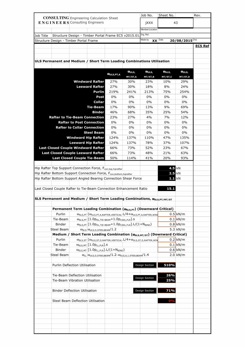
Job No. Sheet No. Rev.
Job Title
XX
EC5 Ref
ULS Permanent and Medium / Short Term Loading Combinations Utilisation
Windward Rafter 27% 30% 23% 10% 29%
Leeward Rafter 27% 30% 18% 8% 24%
Purlin 219% 241% 213% 75% 254%
Post 0% 0% 0% 0% 0%
Collar 0% 0% 0% 0% 0%
Tie-Beam 17% 90% 13% 9% 69%
Binder 46% 68% 35% 25% 54%
Rafter to Tie-Beam Connection 23% 27% 4% 7% 12%
Rafter to Post Connection 0% 0% 0% 0% 0%
Rafter to Collar Connection 0% 0% 0% 0% 0%
Steel Beam 0% 0% 0% 0% 0%
Windward Hip Rafter 124% 137% 110% 47% 135%
Leeward Hip Rafter 124% 137% 78% 37% 107%
Last Closed Couple Windward Rafter 66% 73% 52% 23% 67%
Last Closed Couple Leeward Rafter 66% 73% 48% 21% 63%
Last Closed Couple Tie-Beam 50% 114% 41% 20% 93%
Hip Rafter Top Support Connection Force, Fcon,top,hiprafter 4.5 kN
Hip Rafter Bottom Support Connection Force, Fcon,bottom,hiprafter 2.5 kN
Hip Rafter Bottom Support Angled Bearing Connection Shear Force 1.1 kN
Last Closed Couple Rafter to Tie-Beam Connection Enhancement Ratio 15.1
SLS Permanent and Medium / Short Term Loading Combinations, ωωωωSLS,PT/MT/ST
Permanent Term Loading Combination (ωωωωSLS,PT) (Downward Critical)
Purlin ωSLS,PT (ωULS,PT,A,RAFTER,VERTICAL.L/4+ωULS,PT,A,RAFTER,WIND/LEEWARD0.5 kN/m
Tie-Beam ωSLS,PT [1.0pDL,TIE-BEAM+1.0pΣSDL,FLR].s 0.1 kN/m
Binder ωSLS,PT [1.0pDL,TIE-BEAM+1.0pΣSDL,FLR].L/(1+NBIND) 0.8 kN/m
Steel Beam ωSLS ωULS,D,STEELBEAM/1.2 5.3 kN/m
Medium / Short Term Loading Combination (ωωωωSLS,MT/ST) (Downward Critical)
Purlin ωSLS,ST (ωULS,ST,D,RAFTER,VERTICAL.L/4+ωULS,ST,D,RAFTER,WIND/LEEWARD0.2 kN/m
Tie-Beam ωSLS,MT [1.0pLL,FLR].s 0.1 kN/m
Binder ωSLS,MT [1.0pLL,FLR].L/(1+NBIND) 0.6 kN/m
Steel Beam ωLL ωULS,D,STEELBEAM/1.2−ωULS,A,1,STEELBEAM/1.4 2.0 kN/m
Purlin Deflection Utilisation 510%
Tie-Beam Deflection Utilisation 26%
Tie-Beam Vibration Utilisation 25%
Binder Deflection Utilisation 71%
Steel Beam Deflection Utilisation 0%
ωωωωULS,
MT/ST,D
ωωωωULS,PT,A
ωωωωULS,
MT/ST,A
ωωωωULS,
MT/ST,B
ωωωωULS,
MT/ST,C
Structure Design - Timber Portal Frame 20/08/2015
Engineering Calculation Sheet Consulting Engineers jXXX 43
Structure Design - Timber Portal Frame EC5 v2015.01.xlsm
CONSULTING
E N G I N E E R S
Design Section
Design Section
Design Section
Made by Date Chd.
Drg. Ref.
Member/Location

Job No. Sheet No. Rev.
Job Title
XX
EC5 Ref
jXXX 44
Engineering Calculation Sheet Consulting Engineers
Structure Design - Timber Portal Frame 20/08/2015
Structure Design - Timber Portal Frame EC5 v2015.01.xlsm
CONSULTING
E N G I N E E R S
Made by Date Chd.
Drg. Ref.
Member/Location

Job No. Sheet No. Rev.
Job Title
XX
EC5 Ref
45
Structure Design - Timber Portal Frame EC5 v2015.01.xlsm
Engineering Calculation Sheet Consulting Engineers jXXX
Structure Design - Timber Portal Frame 20/08/2015
CONSULTING
E N G I N E E R S
Reaction DiagramBending Moment Diagram
Made by Date Chd.
Drg. Ref.
Member/Location

Job No. Sheet No. Rev.
Job Title
XX
EC5 Ref
Structure Design - Timber Portal Frame 20/08/2015
Engineering Calculation Sheet Consulting Engineers jXXX 46
Structure Design - Timber Portal Frame EC5 v2015.01.xlsm
CONSULTING
E N G I N E E R S
Made by Date Chd.
Drg. Ref.
Member/Location
Job No. Sheet No. Rev.
Job Title
XX
EC5 Ref
Engineering Calculation Sheet Consulting Engineers jXXX
Structure Design - Timber Portal Frame EC5 v2015.01.xlsm
Structure Design - Timber Portal Frame
47
20/08/2015
CONSULTING
E N G I N E E R S
Reaction DiagramBending Moment Diagram
Made by Date Chd.
Drg. Ref.
Member/Location
Job No. Sheet No. Rev.
Job Title
XX
EC5 Ref
Structure Design - Timber Portal Frame 20/08/2015
Engineering Calculation Sheet Consulting Engineers jXXX 48
Structure Design - Timber Portal Frame EC5 v2015.01.xlsm
CONSULTING
E N G I N E E R S
Made by Date Chd.
Drg. Ref.
Member/Location

Job No. Sheet No. Rev.
Job Title
XX
EC5 Ref
Structure Design - Timber Portal Frame 20/08/2015
49
Engineering Calculation Sheet Consulting Engineers
Structure Design - Timber Portal Frame EC5 v2015.01.xlsm
jXXX
CONSULTING
E N G I N E E R S
Reaction DiagramBending Moment Diagram
Made by Date Chd.
Drg. Ref.
Member/Location

Job No. Sheet No. Rev.
Job Title
XX
EC5 Ref
Structure Design - Timber Portal Frame 20/08/2015
Engineering Calculation Sheet Consulting Engineers jXXX 50
Structure Design - Timber Portal Frame EC5 v2015.01.xlsm
CONSULTING
E N G I N E E R S
Made by Date Chd.
Drg. Ref.
Member/Location

Job No. Sheet No. Rev.
Job Title
XX
EC5 Ref
Structure Design - Timber Portal Frame EC5 v2015.01.xlsm
Structure Design - Timber Portal Frame 20/08/2015
Engineering Calculation Sheet Consulting Engineers jXXX 51
CONSULTING
E N G I N E E R S
Made by Date Chd.
Drg. Ref.
Member/Location