Job No. Sheet No. Rev. CONSULTING Engineering … · Job No. Sheet No. Rev. Job Title XX EC5 Ref...
50
Job No. Sheet No. Rev. Job Title XX EC5 Ref Timber Material Properties Timber Name or Strength Class Mean Density, ρ mean 600 kg/m 3 Material Safety Factor, γ m (1.30Solid; 1.25Glulam; 1.20LVL) 1.30 Service Class k mod k def k mod k def Class 1 0.60 0.60 0.80 0.25 Class 2 0.60 0.80 0.80 0.25 Class 3 0.50 2.00 0.65 0.75 Permanent Action - ULS Factored (DL+SDL) and SLS Unfactored (DL+SDL) Modification Factor for Temp, Moisture, Load Duration, k mod,pt 0.50 Modification Factor for Creep and Moisture, k def,pt 2.00 Medium Term Action - ULS Factored (DL+SDL+LL) Modification Factor for Temp, Moisture, Load Duration, k mod,mt 0.65 Modification Factor for Creep and Moisture, k def,mt 0.75 Factor for the Quasi-Permanent Value, ψ 2,mt 0.30 Medium Term Action - SLS Unfactored (DL+SDL+LL) For the (DL+SDL) component, the above permanent action values, whilst for the LL component, the above ULS medium term values. Geometry of Floor Joist Span, L (Usually 3.6 - 4.0m) 4.150 m Joist LTB Length, L LTB = L / (1+Struttings) 2.075 m Joist Buckling Length (h-Plane), L euler,h = %.L 4.150 m Joist Buckling Length (b-Plane), L euler,b = %.L 0.830 m Joist Spacing, s (Usually 400mm, 450mm or 600mm) 400 mm Bearing Length for Shear Force, l bearing (>=40mm) 50 mm OK Precamber, u 0 0.0 mm Section Properties Section Scheme and Number of Joist(s), NJ 1 Note NJ multiplies the dead load and divides the loading, ω ; Joist Width, b 47 mm Joist Depth, h 200 mm Recommended depth based on span / depth = 20 208 mm Recommended depth based on span in mm / 24 + 50 223 mm Elastic Section Modulus, W (h-Plane) = [1/12 b.h 3 ]/(h/2) 313 cm 3 Depth h Modifier For Notched Sections, h mod% 80.0% Depth b Modifier For Notched Sections, b mod% (Usually 100.0%) 100.0% Note that all effects are for single joists. Double and triple joists are considered by NJ. Nothing else. Thus the multiple joists need not be fastenned together as their responses are considered to be independent. In reality, joists which are fastenned together at regular intervals would respond in between independent joists and a single joist of thickness the sum of the joists thicknesses; Engineering Calculation Sheet Consulting Engineers jXXX 1 CONSULTING E N G I N E E R S Member Design - Timber Floor EC5 v2015.01.xlsm Member Design - Timber Floor 20/08/2015 Permanent Medium Term Made by Date Chd. Drg. Ref. Member/Location
-
Upload
dangkhuong -
Category
Documents
-
view
231 -
download
0
Transcript of Job No. Sheet No. Rev. CONSULTING Engineering … · Job No. Sheet No. Rev. Job Title XX EC5 Ref...
Job No. Sheet No. Rev.
Job Title
XX
EC5 Ref
Timber Material Properties
Timber Name or Strength Class
Mean Density, ρmean 600 kg/m3
Material Safety Factor, γm (1.30Solid; 1.25Glulam; 1.20LVL) 1.30
Service Class
kmod kdef kmod kdef
Class 1 0.60 0.60 0.80 0.25
Class 2 0.60 0.80 0.80 0.25
Class 3 0.50 2.00 0.65 0.75
Permanent Action - ULS Factored (DL+SDL) and SLS Unfactored (DL+SDL)
Modification Factor for Temp, Moisture, Load Duration, kmod,pt 0.50
Modification Factor for Creep and Moisture, kdef,pt 2.00
Medium Term Action - ULS Factored (DL+SDL+LL)
Modification Factor for Temp, Moisture, Load Duration, kmod,mt 0.65
Modification Factor for Creep and Moisture, kdef,mt 0.75
Factor for the Quasi-Permanent Value, ψ2,mt 0.30
Medium Term Action - SLS Unfactored (DL+SDL+LL)
For the (DL+SDL) component, the above permanent action values,
whilst for the LL component, the above ULS medium term values.
Geometry of Floor
Joist Span, L (Usually 3.6 − 4.0m) 4.150 m
Joist LTB Length, LLTB = L / (1+Struttings) 2.075 m
Joist Buckling Length (h-Plane), Leuler,h = %.L 4.150 m
Joist Buckling Length (b-Plane), Leuler,b = %.L 0.830 m
Joist Spacing, s (Usually 400mm, 450mm or 600mm) 400 mm
Bearing Length for Shear Force, lbearing (>=40mm) 50 mm OK
Precamber, u0 0.0 mm
Section Properties
Section Scheme and Number of Joist(s), NJ 1
Note NJ multiplies the dead load and divides the loading, ω ;
Joist Width, b 47 mm
Joist Depth, h 200 mm
Recommended depth based on span / depth = 20 208 mm
Recommended depth based on span in mm / 24 + 50 223 mm
Elastic Section Modulus, W (h-Plane) = [1/12 b.h3]/(h/2) 313 cm
3
Depth h Modifier For Notched Sections, hmod% 80.0%
Depth b Modifier For Notched Sections, bmod% (Usually 100.0%) 100.0%
Note that all effects are for single joists. Double and triple joists are considered by NJ. Nothing else.
Thus the multiple joists need not be fastenned together as their responses are considered to be
independent. In reality, joists which are fastenned together at regular intervals would respond
in between independent joists and a single joist of thickness the sum of the joists thicknesses;
Engineering Calculation Sheet
Consulting Engineers jXXX 1
CONSULTING
E N G I N E E R S
Member Design - Timber Floor EC5 v2015.01.xlsm
Member Design - Timber Floor 20/08/2015
Permanent Medium Term
Made by Date Chd.
Drg. Ref.
Member/Location
Job No. Sheet No. Rev.
Job Title
XX
EC5 Ref
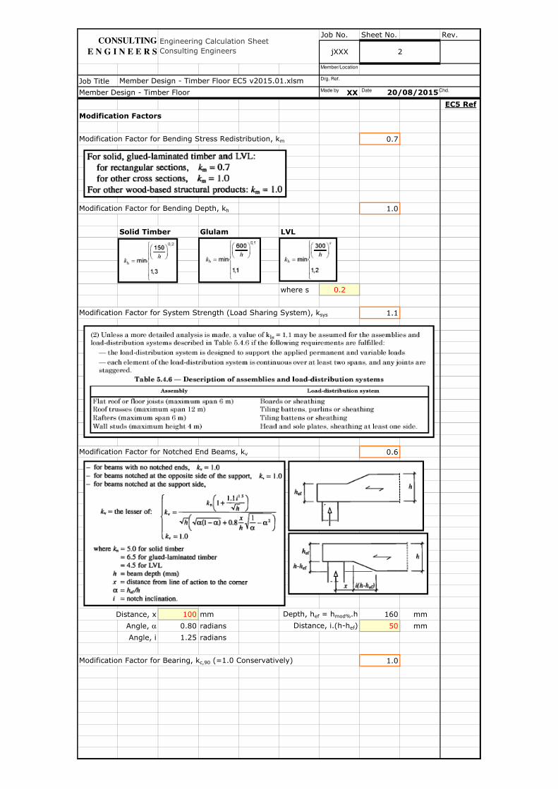
Modification Factors
Modification Factor for Bending Stress Redistribution, km 0.7
Modification Factor for Bending Depth, kh 1.0
Solid Timber Glulam LVL
where s 0.2
Modification Factor for System Strength (Load Sharing System), ksys 1.1
Modification Factor for Notched End Beams, kv 0.6
Distance, x 100 mm Depth, hef = hmod%.h 160 mm
Angle, α 0.80 radians Distance, i.(h-hef) 50 mm
Angle, i 1.25 radians
Modification Factor for Bearing, kc,90 (=1.0 Conservatively) 1.0
Member Design - Timber Floor EC5 v2015.01.xlsm
Member Design - Timber Floor 20/08/2015
Engineering Calculation Sheet
Consulting Engineers jXXX 2
CONSULTING
E N G I N E E R S
Made by Date Chd.
Drg. Ref.
Member/Location
Job No. Sheet No. Rev.
Job Title
XX
EC5 Ref
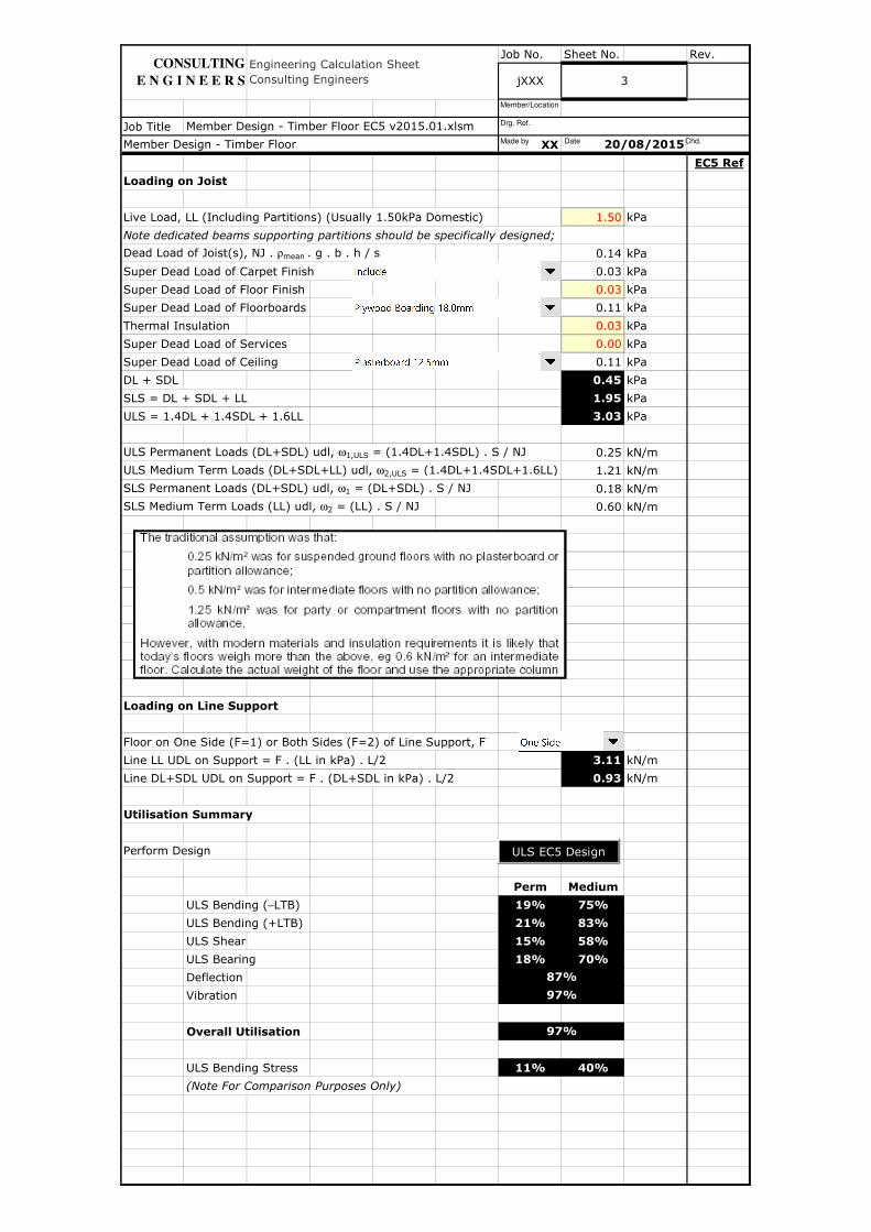
Loading on Joist
Live Load, LL (Including Partitions) (Usually 1.50kPa Domestic) 1.50 kPa
Note dedicated beams supporting partitions should be specifically designed;
Dead Load of Joist(s), NJ . ρmean . g . b . h / s 0.14 kPa
Super Dead Load of Carpet Finish 0.03 kPa
Super Dead Load of Floor Finish 0.03 kPa
Super Dead Load of Floorboards 0.11 kPa
Thermal Insulation 0.03 kPa
Super Dead Load of Services 0.00 kPa
Super Dead Load of Ceiling 0.11 kPa
DL + SDL 0.45 kPa
SLS = DL + SDL + LL 1.95 kPa
ULS = 1.4DL + 1.4SDL + 1.6LL 3.03 kPa
ULS Permanent Loads (DL+SDL) udl, ω1,ULS = (1.4DL+1.4SDL) . S / NJ 0.25 kN/m
ULS Medium Term Loads (DL+SDL+LL) udl, ω2,ULS = (1.4DL+1.4SDL+1.6LL) . S / NJ1.21 kN/m
SLS Permanent Loads (DL+SDL) udl, ω1 = (DL+SDL) . S / NJ 0.18 kN/m
SLS Medium Term Loads (LL) udl, ω2 = (LL) . S / NJ 0.60 kN/m
Loading on Line Support
Floor on One Side (F=1) or Both Sides (F=2) of Line Support, F
Line LL UDL on Support = F . (LL in kPa) . L/2 3.11 kN/m
Line DL+SDL UDL on Support = F . (DL+SDL in kPa) . L/2 0.93 kN/m
Utilisation Summary
Perform Design
Perm Medium
ULS Bending (−LTB) 19% 75%
ULS Bending (+LTB) 21% 83%
ULS Shear 15% 58%
ULS Bearing 18% 70%
Deflection
Vibration
Overall Utilisation
ULS Bending Stress 11% 40%
(Note For Comparison Purposes Only)
Engineering Calculation Sheet
Consulting Engineers
Member Design - Timber Floor EC5 v2015.01.xlsm
Member Design - Timber Floor
97%
87%
97%
jXXX 3
20/08/2015
CONSULTING
E N G I N E E R S
ULS EC5 Design
Made by Date Chd.
Drg. Ref.
Member/Location
Job No. Sheet No. Rev.
Job Title
XX
EC5 Ref
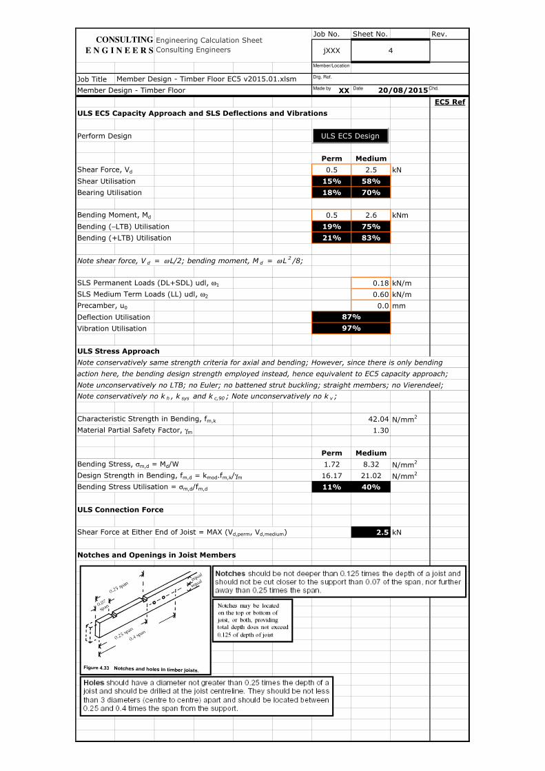
ULS EC5 Capacity Approach and SLS Deflections and Vibrations
Perform Design
Perm Medium
Shear Force, Vd 0.5 2.5 kN
Shear Utilisation 15% 58%
Bearing Utilisation 18% 70%
Bending Moment, Md 0.5 2.6 kNm
Bending (−LTB) Utilisation 19% 75%
Bending (+LTB) Utilisation 21% 83%
Note shear force, V d = ω L/2; bending moment, M d = ω L2/8;
SLS Permanent Loads (DL+SDL) udl, ω1 0.18 kN/m
SLS Medium Term Loads (LL) udl, ω2 0.60 kN/m
Precamber, u0 0.0 mm
Deflection Utilisation
Vibration Utilisation
ULS Stress Approach
Note conservatively same strength criteria for axial and bending; However, since there is only bending
action here, the bending design strength employed instead, hence equivalent to EC5 capacity approach;
Note unconservatively no LTB; no Euler; no battened strut buckling; straight members; no Vierendeel;
Note conservatively no k h , k sys and k c,90 ; Note unconservatively no k v ;
Characteristic Strength in Bending, fm,k 42.04 N/mm2
Material Partial Safety Factor, γm 1.30
Perm Medium
Bending Stress, σm,d = Md/W 1.72 8.32 N/mm2
Design Strength in Bending, fm,d = kmod.fm,k/γm 16.17 21.02 N/mm2
Bending Stress Utilisation = σm,d/fm,d 11% 40%
ULS Connection Force
Shear Force at Either End of Joist = MAX (Vd,perm, Vd,medium) 2.5 kN
Notches and Openings in Joist Members
87%
97%
Engineering Calculation Sheet
Consulting Engineers jXXX 4
Member Design - Timber Floor 20/08/2015
Member Design - Timber Floor EC5 v2015.01.xlsm
CONSULTING
E N G I N E E R S
ULS EC5 Design
Made by Date Chd.
Drg. Ref.
Member/Location
Job No. Sheet No. Rev.
Job Title
XX
EC5 Ref
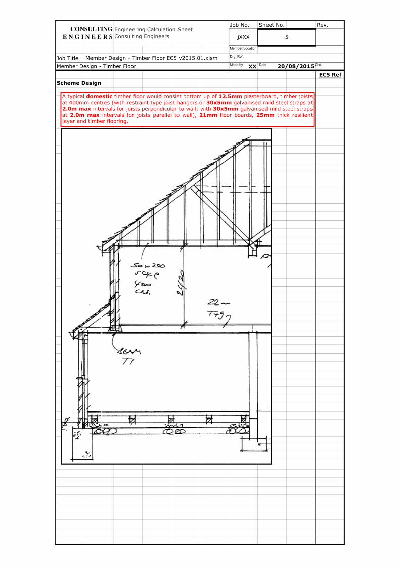
Scheme Design
Engineering Calculation Sheet
Consulting Engineers
Member Design - Timber Floor EC5 v2015.01.xlsm
Member Design - Timber Floor 20/08/2015
CONSULTING
E N G I N E E R S jXXX 5
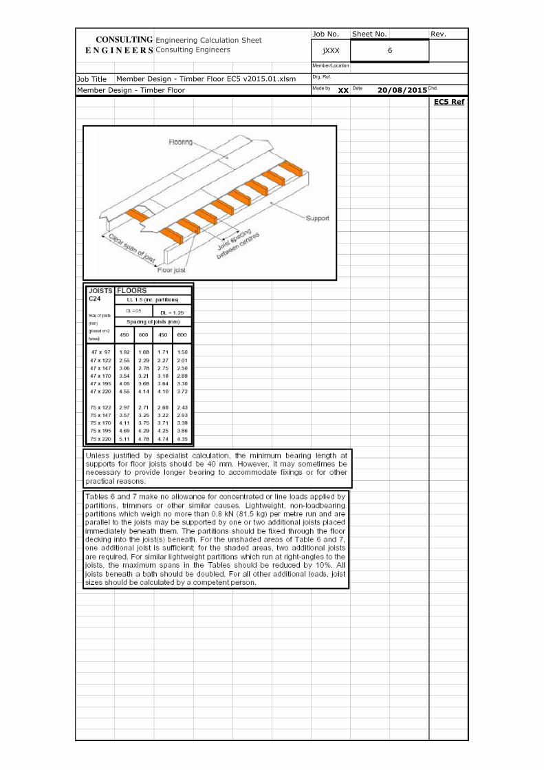
A typical domestic timber floor would consist bottom up of 12.5mm plasterboard, timber joists
at 400mm centres (with restraint type joist hangers or 30x5mm galvanised mild steel straps at2.0m max intervals for joists perpendicular to wall; with 30x5mm galvanised mild steel straps
at 2.0m max intervals for joists parallel to wall), 21mm floor boards, 25mm thick resilientlayer and timber flooring.
Made by Date Chd.
Drg. Ref.
Member/Location
Job No. Sheet No. Rev.
Job Title
XX
EC5 Ref
Member Design - Timber Floor EC5 v2015.01.xlsm
Member Design - Timber Floor 20/08/2015
CONSULTING
E N G I N E E R S
Engineering Calculation Sheet
Consulting Engineers jXXX 6
Made by Date Chd.
Drg. Ref.
Member/Location
Job No. Sheet No. Rev.
Job Title
XX
EC5 Ref
Member Design - Timber Floor
Engineering Calculation Sheet
Consulting Engineers jXXX
20/08/2015
Member Design - Timber Floor EC5 v2015.01.xlsm
CONSULTING
E N G I N E E R S 7
Made by Date Chd.
Drg. Ref.
Member/Location
Job No. Sheet No. Rev.
Job Title
XX
EC5 Ref
20/08/2015
Engineering Calculation Sheet
Consulting Engineers jXXX 8
Member Design - Timber Floor
Member Design - Timber Floor EC5 v2015.01.xlsm
CONSULTING
E N G I N E E R S
Made by Date Chd.
Drg. Ref.
Member/Location
Job No. Sheet No. Rev.
Job Title
XX
EC5 Ref
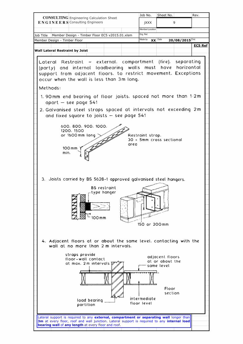
Wall Lateral Restraint by Joist
20/08/2015
Engineering Calculation Sheet
Consulting Engineers jXXX 9
Member Design - Timber Floor EC5 v2015.01.xlsm
Member Design - Timber Floor
CONSULTING
E N G I N E E R S
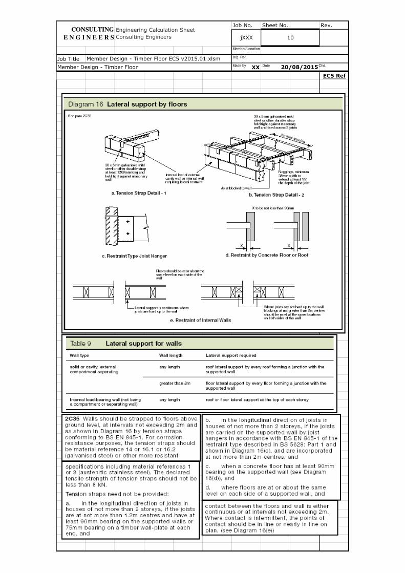
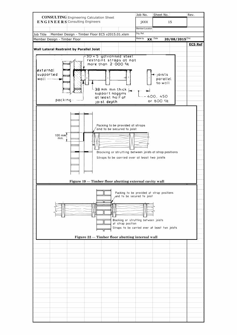
Lateral support is required to any external, compartment or separating wall longer than
3m at every floor, roof and wall junction. Lateral support is required to any internal loadbearing wall of any length at every floor and roof.
Made by Date Chd.
Drg. Ref.
Member/Location
Job No. Sheet No. Rev.
Job Title
XX
EC5 Ref
Member Design - Timber Floor
10
20/08/2015
Engineering Calculation Sheet
Consulting Engineers
Member Design - Timber Floor EC5 v2015.01.xlsm
jXXX
CONSULTING
E N G I N E E R S
Made by Date Chd.
Drg. Ref.
Member/Location
Job No. Sheet No. Rev.
Job Title
XX
EC5 Ref
Wall Lateral Restraint by Perpendicular Joist (Bearing Connection)
Member Design - Timber Floor EC5 v2015.01.xlsm
Engineering Calculation Sheet
Consulting Engineers jXXX
Member Design - Timber Floor 20/08/2015
11
CONSULTING
E N G I N E E R S
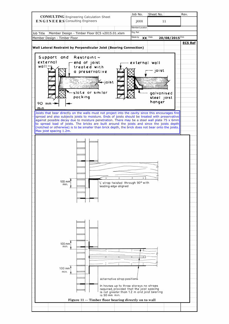
Joists that bear directly on the walls must not project into the cavity since this encourages fire
spread and also subjects joists to moisture. Ends of joists should be treated with preservativeagainst possible decay due to moisture penetration. There may be a steel wall plate 75 x 6mm
to spread load of joists. The bricks are built around the joists and since the joists depth(notched or otherwise) is to be smaller than brick depth, the brick does not bear onto the joists.
Max joist spacing 1.2m.
Made by Date Chd.
Drg. Ref.
Member/Location
Job No. Sheet No. Rev.
Job Title
XX
EC5 Ref
Wall Lateral Restraint by Perpendicular Joist (Joist Hanger)
Member Design - Timber Floor EC5 v2015.01.xlsm
Member Design - Timber Floor 20/08/2015
Engineering Calculation Sheet
Consulting Engineers jXXX 12
CONSULTING
E N G I N E E R S
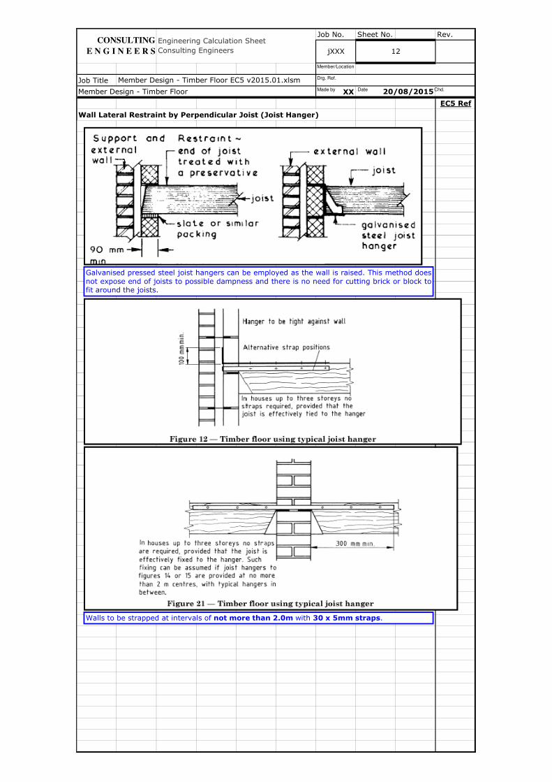
Galvanised pressed steel joist hangers can be employed as the wall is raised. This method does
not expose end of joists to possible dampness and there is no need for cutting brick or block tofit around the joists.
Walls to be strapped at intervals of not more than 2.0m with 30 x 5mm straps.
Made by Date Chd.
Drg. Ref.
Member/Location
Job No. Sheet No. Rev.
Job Title
XX
EC5 Ref
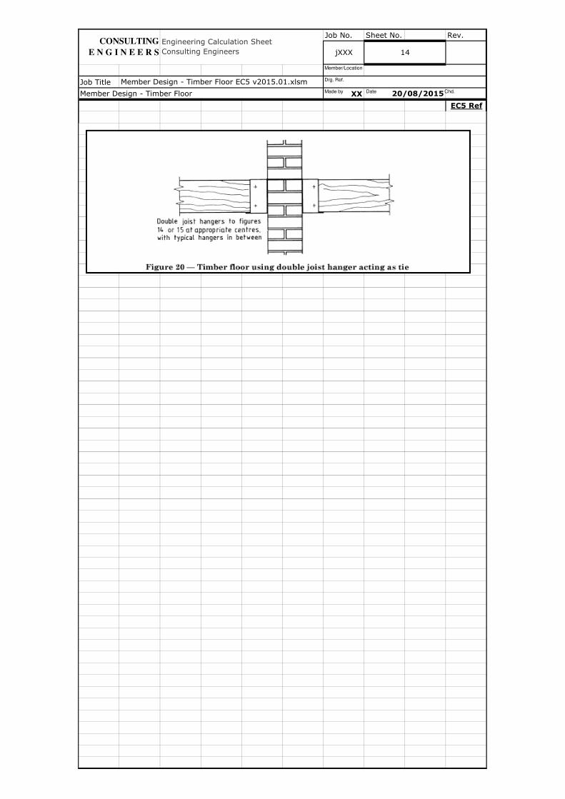
Wall Lateral Restraint by Perpendicular Joist (Restraint Type Joist Hanger)
20/08/2015
jXXX 13
Member Design - Timber Floor
Member Design - Timber Floor EC5 v2015.01.xlsm
Engineering Calculation Sheet
Consulting Engineers
CONSULTING
E N G I N E E R S
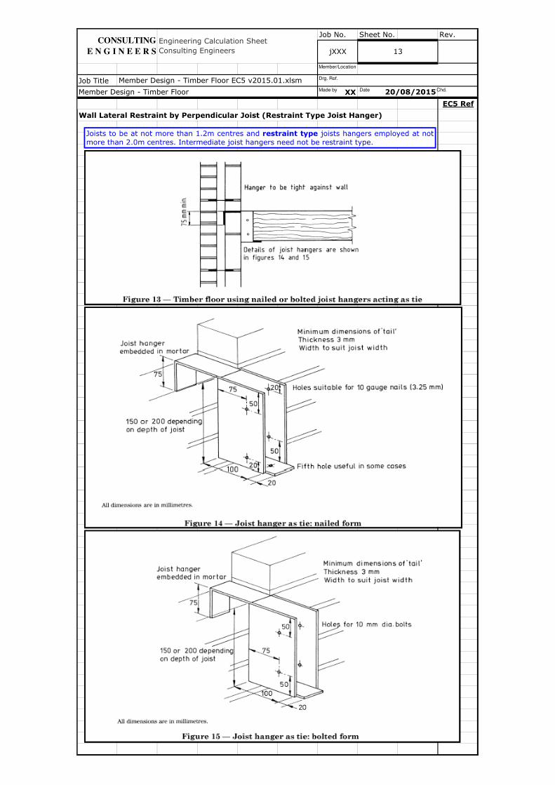
Joists to be at not more than 1.2m centres and restraint type joists hangers employed at not
more than 2.0m centres. Intermediate joist hangers need not be restraint type.
Made by Date Chd.
Drg. Ref.
Member/Location
Job No. Sheet No. Rev.
Job Title
XX
EC5 Ref
Member Design - Timber Floor EC5 v2015.01.xlsm
Member Design - Timber Floor 20/08/2015
Engineering Calculation Sheet
Consulting Engineers jXXX 14
CONSULTING
E N G I N E E R S
Made by Date Chd.
Drg. Ref.
Member/Location
Job No. Sheet No. Rev.
Job Title
XX
EC5 Ref
Wall Lateral Restraint by Parallel Joist
Member Design - Timber Floor 20/08/2015
Engineering Calculation Sheet
Consulting Engineers jXXX 15
Member Design - Timber Floor EC5 v2015.01.xlsm
CONSULTING
E N G I N E E R S
Made by Date Chd.
Drg. Ref.
Member/Location
Job No. Sheet No. Rev.
Job Title
XX
EC5 Ref
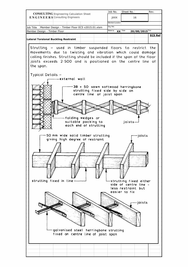
Lateral Torsional Buckling Restraint
Engineering Calculation Sheet
Consulting Engineers jXXX
Member Design - Timber Floor EC5 v2015.01.xlsm
Member Design - Timber Floor 20/08/2015
16
CONSULTING
E N G I N E E R S
Made by Date Chd.
Drg. Ref.
Member/Location
Job No. Sheet No. Rev.
Job Title
XX
EC5 Ref
Member Design - Timber Floor EC5 v2015.01.xlsm
Engineering Calculation Sheet
Consulting Engineers jXXX 17
Member Design - Timber Floor 20/08/2015
CONSULTING
E N G I N E E R S
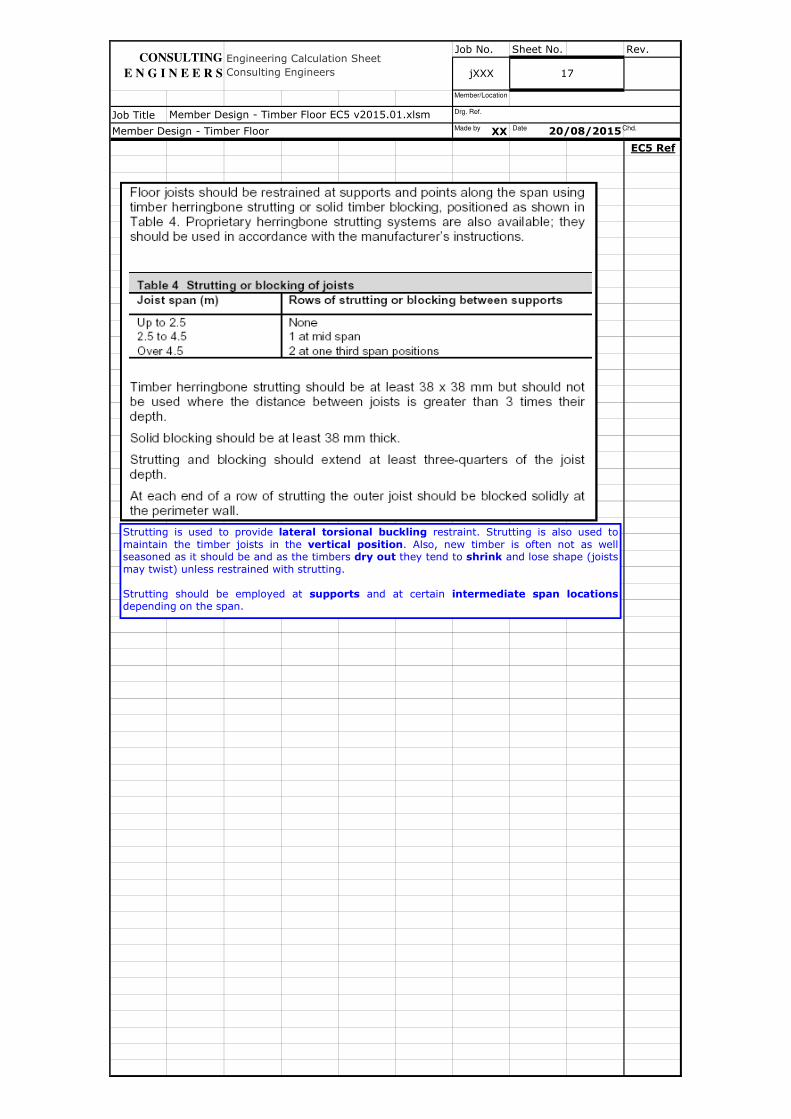
Strutting is used to provide lateral torsional buckling restraint. Strutting is also used to
maintain the timber joists in the vertical position. Also, new timber is often not as wellseasoned as it should be and as the timbers dry out they tend to shrink and lose shape (joists
may twist) unless restrained with strutting.
Strutting should be employed at supports and at certain intermediate span locationsdepending on the span.
Made by Date Chd.
Drg. Ref.
Member/Location
Job No. Sheet No. Rev.
Job Title
XX
EC5 Ref
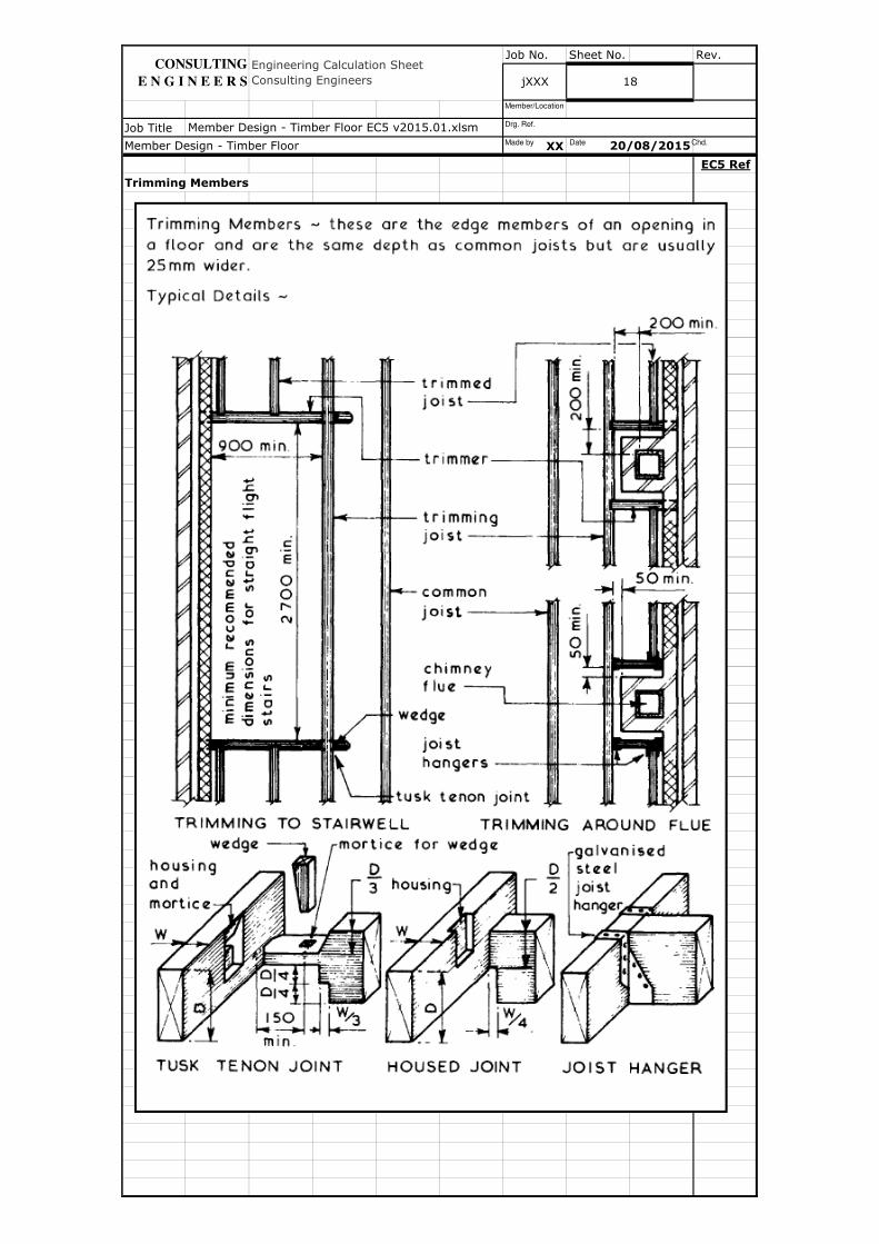
Trimming Members
Member Design - Timber Floor EC5 v2015.01.xlsm
Member Design - Timber Floor 20/08/2015
Engineering Calculation Sheet
Consulting Engineers jXXX 18
CONSULTING
E N G I N E E R S
Made by Date Chd.
Drg. Ref.
Member/Location
Job No. Sheet No. Rev.
Job Title
XX
EC5 Ref
Floor Boards
Member Design - Timber Floor EC5 v2015.01.xlsm
Member Design - Timber Floor 20/08/2015
CONSULTING
E N G I N E E R S
Engineering Calculation Sheet
Consulting Engineers jXXX 19
Made by Date Chd.
Drg. Ref.
Member/Location
Job No. Sheet No. Rev.
Job Title
XX
EC5 Ref
Engineering Calculation Sheet
Consulting Engineers jXXX 20
Member Design - Timber Floor EC5 v2015.01.xlsm
Member Design - Timber Floor 20/08/2015
CONSULTING
E N G I N E E R S
Made by Date Chd.
Drg. Ref.
Member/Location
Job No. Sheet No. Rev.
Job Title
XX
EC5 Ref
Engineering Calculation Sheet
Consulting Engineers jXXX 21
Member Design - Timber Floor EC5 v2015.01.xlsm
Member Design - Timber Floor 20/08/2015
CONSULTING
E N G I N E E R S
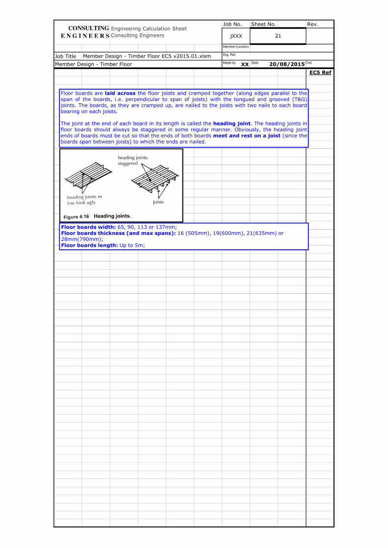
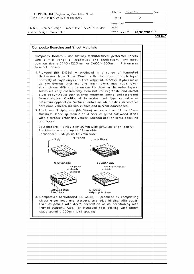
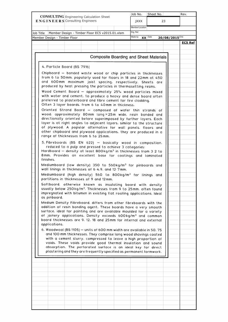
Floor boards are laid across the floor joists and cramped together (along edges parallel to the
span of the boards, i.e. perpendicular to span of joists) with the tongued and grooved (T&G)joints. The boards, as they are cramped up, are nailed to the joists with two nails to each board
bearing on each joists.
The joint at the end of each board in its length is called the heading joint. The heading joints infloor boards should always be staggered in some regular manner. Obviously, the heading joint
ends of boards must be cut so that the ends of both boards meet and rest on a joist (since theboards span between joists) to which the ends are nailed.
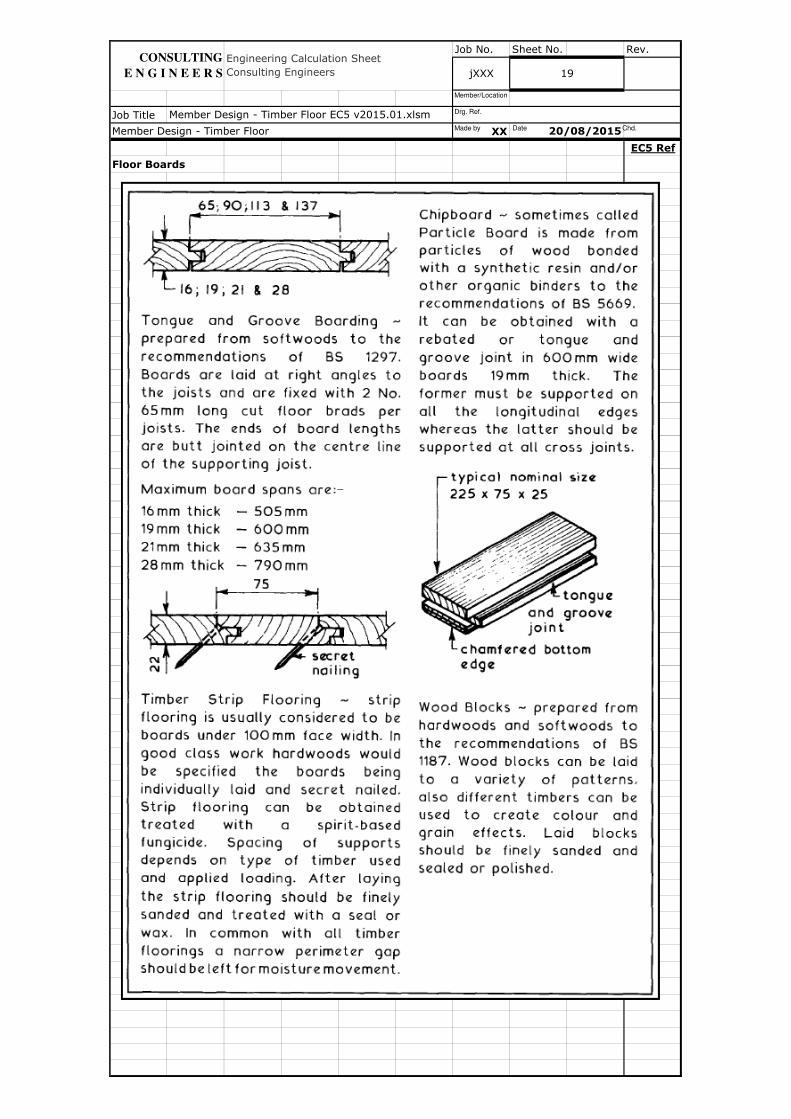
Floor boards width: 65, 90, 113 or 137mm;
Floor boards thickness (and max spans): 16 (505mm), 19(600mm), 21(635mm) or 28mm(790mm);
Floor boards length: Up to 5m;
Made by Date Chd.
Drg. Ref.
Member/Location
Job No. Sheet No. Rev.
Job Title
XX
EC5 Ref
Member Design - Timber Floor 20/08/2015
Engineering Calculation Sheet
Consulting Engineers jXXX 22
Member Design - Timber Floor EC5 v2015.01.xlsm
CONSULTING
E N G I N E E R S
Made by Date Chd.
Drg. Ref.
Member/Location
Job No. Sheet No. Rev.
Job Title
XX
EC5 Ref
Member Design - Timber Floor 20/08/2015
Engineering Calculation Sheet
Consulting Engineers jXXX 23
CONSULTING
E N G I N E E R S
Member Design - Timber Floor EC5 v2015.01.xlsmMade by Date Chd.
Drg. Ref.
Member/Location

Job No. Sheet No. Rev.
Job Title
XX
EC5 Ref
Engineering Calculation Sheet
Consulting Engineers jXXX 24
Member Design - Timber Floor EC5 v2015.01.xlsm
Member Design - Timber Floor 20/08/2015
CONSULTING
E N G I N E E R S
Made by Date Chd.
Drg. Ref.
Member/Location

Job No. Sheet No. Rev.
Job Title
XX
EC5 Ref
Member Design - Timber Floor EC5 v2015.01.xlsm
Member Design - Timber Floor 20/08/2015
Engineering Calculation Sheet
Consulting Engineers jXXX 25
CONSULTING
E N G I N E E R S
Made by Date Chd.
Drg. Ref.
Member/Location
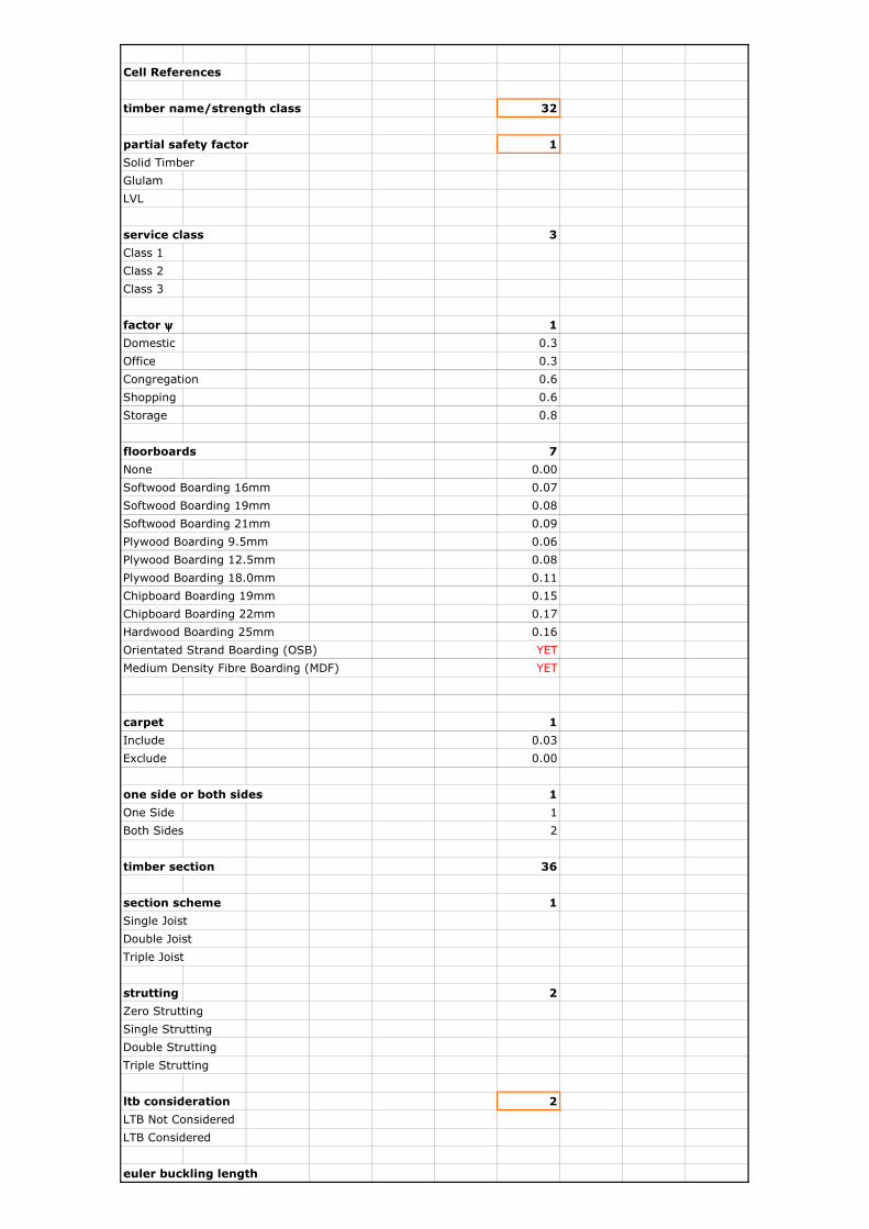
Cell References
timber name/strength class 32
partial safety factor 1
Solid Timber
Glulam
LVL
service class 3
Class 1
Class 2
Class 3
factor ψψψψ 1
Domestic 0.3
Office 0.3
Congregation 0.6
Shopping 0.6
Storage 0.8
floorboards 7
None 0.00
Softwood Boarding 16mm 0.07
Softwood Boarding 19mm 0.08
Softwood Boarding 21mm 0.09
Plywood Boarding 9.5mm 0.06
Plywood Boarding 12.5mm 0.08
Plywood Boarding 18.0mm 0.11
Chipboard Boarding 19mm 0.15
Chipboard Boarding 22mm 0.17
Hardwood Boarding 25mm 0.16
Orientated Strand Boarding (OSB) YET
Medium Density Fibre Boarding (MDF) YET
carpet 1
Include 0.03
Exclude 0.00
one side or both sides 1
One Side 1
Both Sides 2
timber section 36
section scheme 1
Single Joist
Double Joist
Triple Joist
strutting 2
Zero Strutting
Single Strutting
Double Strutting
Triple Strutting
ltb consideration 2
LTB Not Considered
LTB Considered
euler buckling length
Job No. Sheet No. Rev.
Job Title
XX
EC5 Ref
Fire Resistance
Member Design - Timber Floor EC5 v2015.01.xlsm
Member Design - Timber Floor 20/08/2015
Engineering Calculation Sheet
Consulting Engineers jXXX 26
CONSULTING
E N G I N E E R S
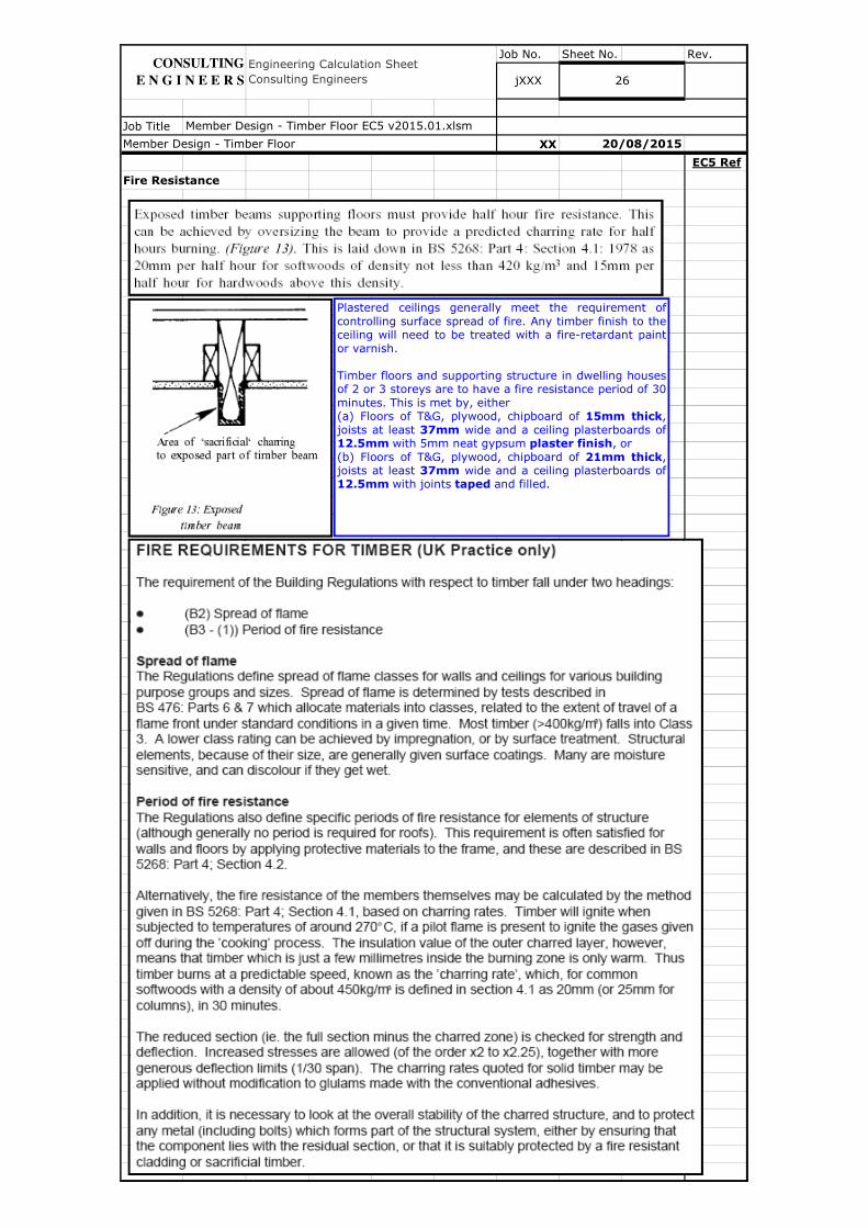
Plastered ceilings generally meet the requirement of
controlling surface spread of fire. Any timber finish to theceiling will need to be treated with a fire-retardant paint
or varnish.
Timber floors and supporting structure in dwelling housesof 2 or 3 storeys are to have a fire resistance period of 30
minutes. This is met by, either(a) Floors of T&G, plywood, chipboard of 15mm thick,
joists at least 37mm wide and a ceiling plasterboards of12.5mm with 5mm neat gypsum plaster finish, or
(b) Floors of T&G, plywood, chipboard of 21mm thick,joists at least 37mm wide and a ceiling plasterboards of12.5mm with joints taped and filled.
Job No. Sheet No. Rev.
Job Title
XX
EC5 Ref
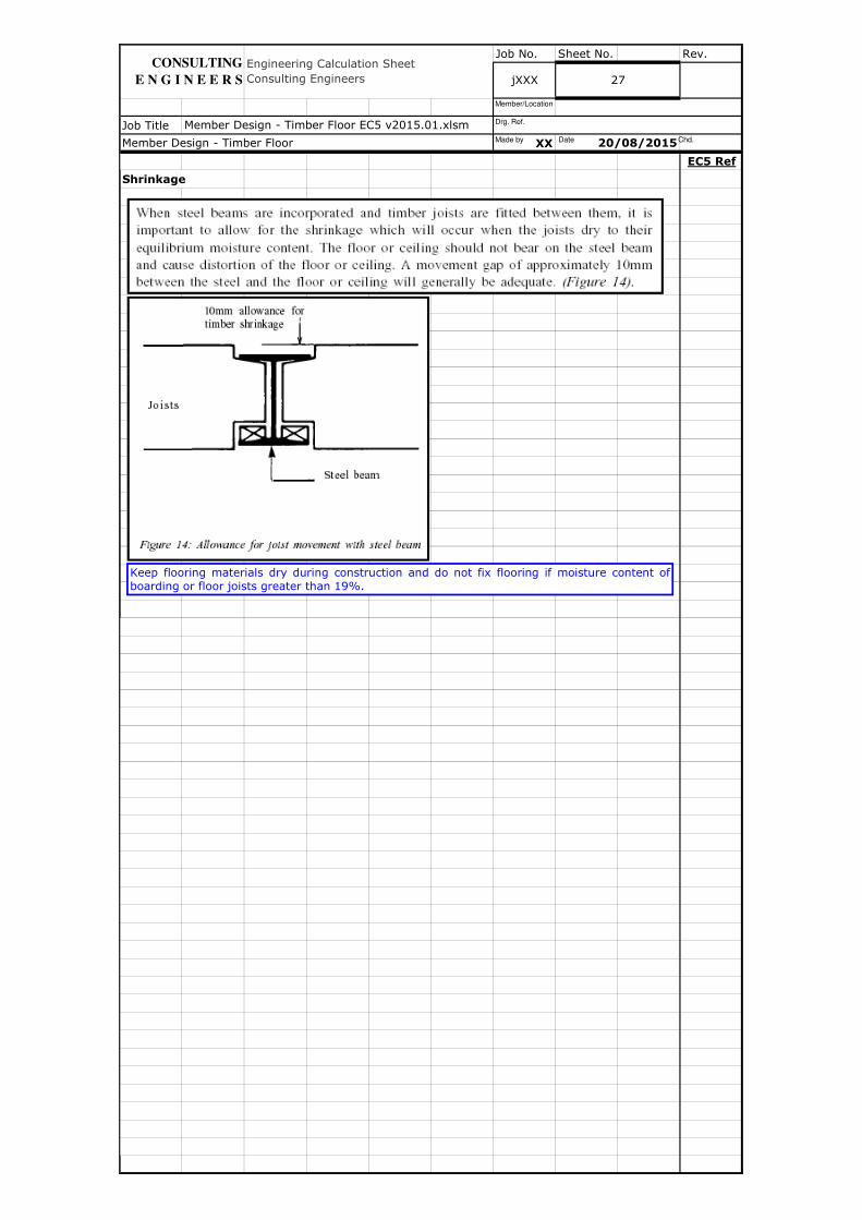
Shrinkage
Member Design - Timber Floor EC5 v2015.01.xlsm
Member Design - Timber Floor 20/08/2015
Engineering Calculation Sheet
Consulting Engineers jXXX 27
CONSULTING
E N G I N E E R S
Keep flooring materials dry during construction and do not fix flooring if moisture content of
boarding or floor joists greater than 19%.
Made by Date Chd.
Drg. Ref.
Member/Location
Job No. Sheet No. Rev.
Job Title
XX
EC5 Ref
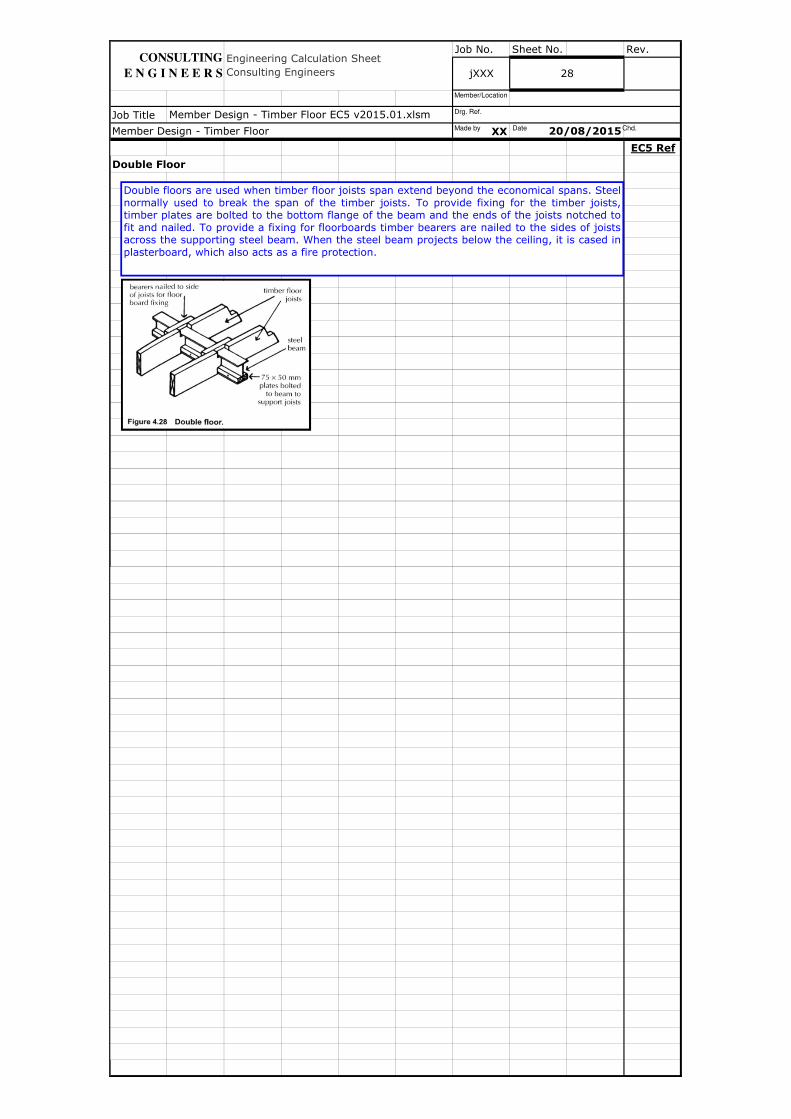
Double Floor
Member Design - Timber Floor EC5 v2015.01.xlsm
Member Design - Timber Floor 20/08/2015
Engineering Calculation Sheet
Consulting Engineers jXXX 28
CONSULTING
E N G I N E E R S
Double floors are used when timber floor joists span extend beyond the economical spans. Steel
normally used to break the span of the timber joists. To provide fixing for the timber joists,timber plates are bolted to the bottom flange of the beam and the ends of the joists notched to
fit and nailed. To provide a fixing for floorboards timber bearers are nailed to the sides of joistsacross the supporting steel beam. When the steel beam projects below the ceiling, it is cased in
plasterboard, which also acts as a fire protection.
Made by Date Chd.
Drg. Ref.
Member/Location
Job No. Sheet No. Rev.
Job Title
XX
EC5 Ref
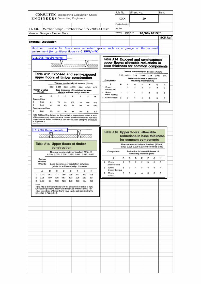
Thermal Insulation
Member Design - Timber Floor EC5 v2015.01.xlsm
Member Design - Timber Floor 20/08/2015
Engineering Calculation Sheet
Consulting Engineers jXXX 29
CONSULTING
E N G I N E E R S
Maximum U−value for floors over unheated spaces such as a garage or the external
environment (for cantilever floors) is 0.25W/m2K.
L1:1995 Requirements
L1:2002 Requirements
Made by Date Chd.
Drg. Ref.
Member/Location
Job No. Sheet No. Rev.
Job Title
XX
EC5 Ref
Member Design - Timber Floor EC5 v2015.01.xlsm
Member Design - Timber Floor 20/08/2015
Engineering Calculation Sheet
Consulting Engineers jXXX 30
CONSULTING
E N G I N E E R S
Made by Date Chd.
Drg. Ref.
Member/Location
Job No. Sheet No. Rev.
Job Title
XX
EC5 Ref
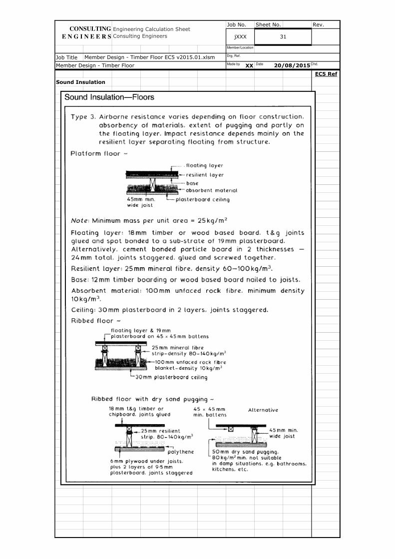
Sound Insulation
20/08/2015
Member Design - Timber Floor EC5 v2015.01.xlsm
Engineering Calculation Sheet
Consulting Engineers
Member Design - Timber Floor
jXXX 31
CONSULTING
E N G I N E E R S
Made by Date Chd.
Drg. Ref.
Member/Location
Job No. Sheet No. Rev.
Job Title
XX
EC5 Ref
Member Design - Timber Floor 20/08/2015
Member Design - Timber Floor EC5 v2015.01.xlsm
Engineering Calculation Sheet
Consulting Engineers jXXX 32
CONSULTING
E N G I N E E R S
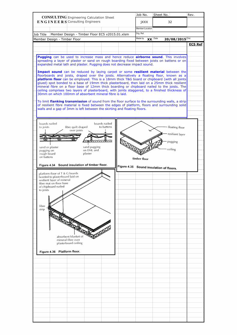
Pugging can be used to increase mass and hence reduce airborne sound. This involves
spreading a layer of plaster or sand on rough boarding fixed between joists on battens or onexpanded metal lath and plaster. Pugging does not decrease impact sound.
Impact sound can be reduced by laying carpet or some resilient material between the
floorboards and joists, draped over the joists. Alternatively a floating floor, known as aplatform floor can be employed. This is a 18mm thick T&G board or chipboard (with all joints
glued) spot bonded to a base of 19mm thick plasterboard, then laid on a 25mm thick resilientmineral fibre on a floor base of 12mm thick boarding or chipboard nailed to the joists. The
ceiling comprises two layers of plasterboard, with joints staggered, to a finished thickness of30mm on which 100mm of absorbent mineral fibre is laid.
To limit flanking transmission of sound from the floor surface to the surrounding walls, a stripof resilient fibre material is fixed between the edges of platform, floors and surrounding solid
walls and a gap of 3mm is left between the skirting and floating floors.
Made by Date Chd.
Drg. Ref.
Member/Location
Job No. Sheet No. Rev.
Job Title
XX
EC5 Ref
Member Design - Timber Floor EC5 v2015.01.xlsm
jXXX 33
Member Design - Timber Floor 20/08/2015
Engineering Calculation Sheet
Consulting Engineers
CONSULTING
E N G I N E E R S
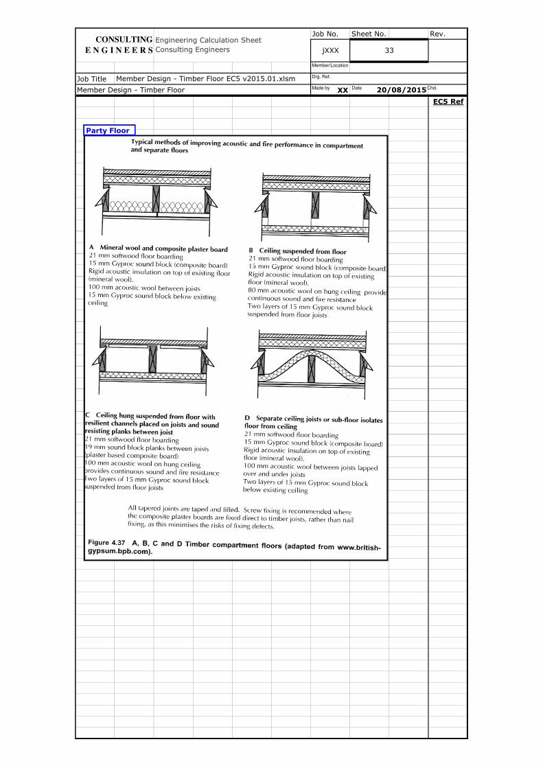
Party Floor
Made by Date Chd.
Drg. Ref.
Member/Location
Job No. Sheet No. Rev.
Job Title
XX
EC5 Ref
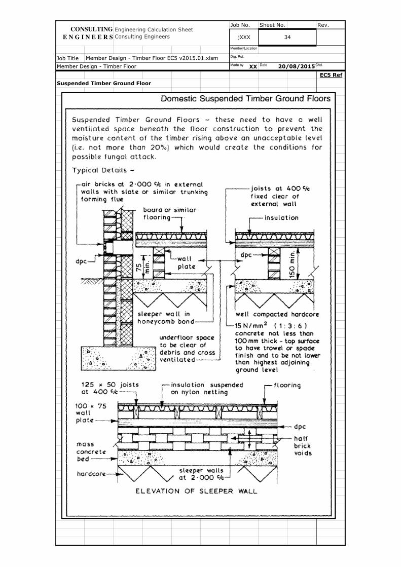
Suspended Timber Ground Floor
Member Design - Timber Floor EC5 v2015.01.xlsm
jXXX
Member Design - Timber Floor 20/08/2015
Engineering Calculation Sheet
Consulting Engineers 34
CONSULTING
E N G I N E E R S
Made by Date Chd.
Drg. Ref.
Member/Location
Job No. Sheet No. Rev.
Job Title
XX
EC5 Ref
Member Design - Timber Floor 20/08/2015
Member Design - Timber Floor EC5 v2015.01.xlsm
Engineering Calculation Sheet
Consulting Engineers jXXX 35
CONSULTING
E N G I N E E R S
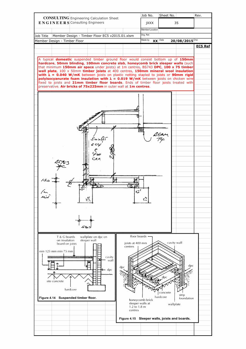
A typical domestic suspended timber ground floor would consist bottom up of 150mm
hardcore, 50mm blinding, 100mm concrete slab, honeycomb brick sleeper walls (suchthat minimum 150mm air space under joists) at 1m centres, BS743 DPC, 100 x 75 timber
wall plate, 100 x 50mm timber joists at 400 centres, 150mm mineral wool insulationwith λλλλ = 0.040 W/mK between joists on plastic netting stapled to joists or 90mm rigid
polyisocyanurate foam insulation with λλλλ = 0.019 W/mK between joists on chicken wire
fixed to joists and 21mm timber floor boards. Ends of timber floor joists treated with
preservative. Air bricks of 75x225mm in outer wall at 1m centres.
Made by Date Chd.
Drg. Ref.
Member/Location
Job No. Sheet No. Rev.
Job Title
XX
EC5 Ref
Member Design - Timber Floor 20/08/2015
Member Design - Timber Floor EC5 v2015.01.xlsm
Engineering Calculation Sheet
Consulting Engineers jXXX 36
CONSULTING
E N G I N E E R S
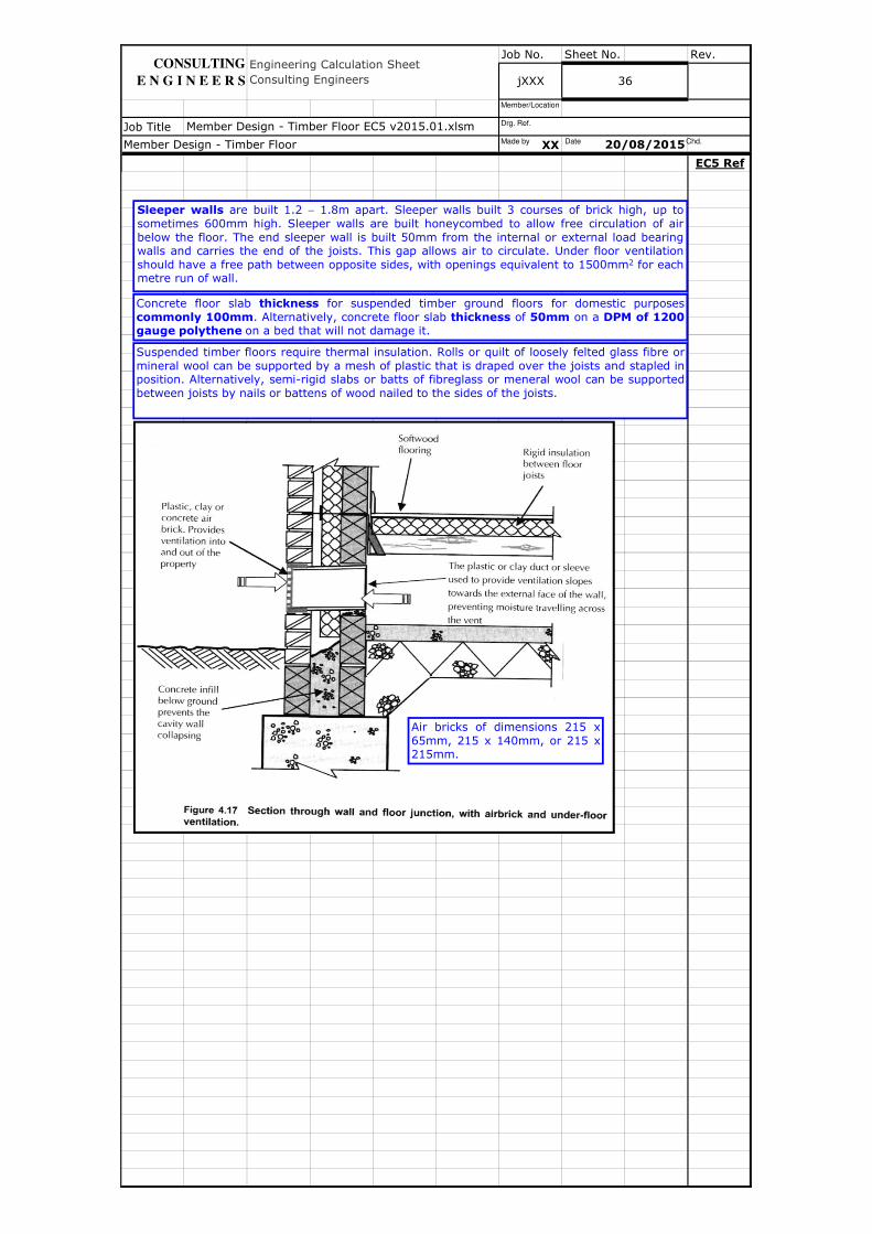
Air bricks of dimensions 215 x
65mm, 215 x 140mm, or 215 x215mm.
Sleeper walls are built 1.2 − 1.8m apart. Sleeper walls built 3 courses of brick high, up to
sometimes 600mm high. Sleeper walls are built honeycombed to allow free circulation of air
below the floor. The end sleeper wall is built 50mm from the internal or external load bearingwalls and carries the end of the joists. This gap allows air to circulate. Under floor ventilation
should have a free path between opposite sides, with openings equivalent to 1500mm2 for eachmetre run of wall.
Concrete floor slab thickness for suspended timber ground floors for domestic purposes
commonly 100mm. Alternatively, concrete floor slab thickness of 50mm on a DPM of 1200gauge polythene on a bed that will not damage it.
Suspended timber floors require thermal insulation. Rolls or quilt of loosely felted glass fibre or
mineral wool can be supported by a mesh of plastic that is draped over the joists and stapled inposition. Alternatively, semi-rigid slabs or batts of fibreglass or meneral wool can be supported
between joists by nails or battens of wood nailed to the sides of the joists.
Made by Date Chd.
Drg. Ref.
Member/Location

Job No. Sheet No. Rev.
Job Title
XX
EC5 Ref
Member Design - Timber Floor 20/08/2015
Member Design - Timber Floor EC5 v2015.01.xlsm
jXXX 37
Engineering Calculation Sheet
Consulting Engineers
CONSULTING
E N G I N E E R S
Made by Date Chd.
Drg. Ref.
Member/Location

Job No. Sheet No. Rev.
Job Title
XX
EC5 Ref
Member Design - Timber Floor 20/08/2015
Member Design - Timber Floor EC5 v2015.01.xlsm
38jXXX
Engineering Calculation Sheet
Consulting Engineers
CONSULTING
E N G I N E E R S
Made by Date Chd.
Drg. Ref.
Member/Location

Job No. Sheet No. Rev.
Job Title
XX
EC5 Ref
Member Design - Timber Floor 20/08/2015
Member Design - Timber Floor EC5 v2015.01.xlsm
Engineering Calculation Sheet
Consulting Engineers jXXX 39
CONSULTING
E N G I N E E R S
Made by Date Chd.
Drg. Ref.
Member/Location

Job No. Sheet No. Rev.
Job Title
XX
EC5 Ref
Member Design - Timber Floor 20/08/2015
Member Design - Timber Floor EC5 v2015.01.xlsm
Engineering Calculation Sheet
Consulting Engineers jXXX 40
CONSULTING
E N G I N E E R S
Made by Date Chd.
Drg. Ref.
Member/Location
Job No. Sheet No. Rev.
Job Title
XX
EC5 Ref
Member Design - Timber Floor 20/08/2015
Member Design - Timber Floor EC5 v2015.01.xlsm
jXXX 41
Engineering Calculation Sheet
Consulting Engineers
CONSULTING
E N G I N E E R S
Made by Date Chd.
Drg. Ref.
Member/Location

Job No. Sheet No. Rev.
Job Title
XX
EC5 Ref
Member Design - Timber Floor 20/08/2015
Member Design - Timber Floor EC5 v2015.01.xlsm
42jXXX
Engineering Calculation Sheet
Consulting Engineers
CONSULTING
E N G I N E E R S
Made by Date Chd.
Drg. Ref.
Member/Location

Job No. Sheet No. Rev.
Job Title
XX
EC5 Ref
Member Design - Timber Floor 20/08/2015
Member Design - Timber Floor EC5 v2015.01.xlsm
Engineering Calculation Sheet
Consulting Engineers jXXX 43
CONSULTING
E N G I N E E R S
Made by Date Chd.
Drg. Ref.
Member/Location

Job No. Sheet No. Rev.
Job Title
XX
EC5 Ref
Member Design - Timber Floor 20/08/2015
Member Design - Timber Floor EC5 v2015.01.xlsm
Engineering Calculation Sheet
Consulting Engineers jXXX 44
CONSULTING
E N G I N E E R S
Made by Date Chd.
Drg. Ref.
Member/Location

Job No. Sheet No. Rev.
Job Title
XX
EC5 Ref
Member Design - Timber Floor 20/08/2015
Member Design - Timber Floor EC5 v2015.01.xlsm
jXXX 45
Engineering Calculation Sheet
Consulting Engineers
CONSULTING
E N G I N E E R S
Made by Date Chd.
Drg. Ref.
Member/Location

Job No. Sheet No. Rev.
Job Title
XX
EC5 Ref
Member Design - Timber Floor 20/08/2015
Member Design - Timber Floor EC5 v2015.01.xlsm
46jXXX
Engineering Calculation Sheet
Consulting Engineers
CONSULTING
E N G I N E E R S
Made by Date Chd.
Drg. Ref.
Member/Location

Job No. Sheet No. Rev.
Job Title
XX
EC5 Ref
Member Design - Timber Floor EC5 v2015.01.xlsm
Member Design - Timber Floor 20/08/2015
Engineering Calculation Sheet
Consulting Engineers jXXX 47
CONSULTING
E N G I N E E R S
Made by Date Chd.
Drg. Ref.
Member/Location

Job No. Sheet No. Rev.
Job Title
XX
EC5 Ref
Member Design - Timber Floor EC5 v2015.01.xlsm
Member Design - Timber Floor 20/08/2015
Engineering Calculation Sheet
Consulting Engineers jXXX 48
CONSULTING
E N G I N E E R S
Made by Date Chd.
Drg. Ref.
Member/Location

Job No. Sheet No. Rev.
Job Title
XX
EC5 Ref
Member Design - Timber Floor EC5 v2015.01.xlsm
Member Design - Timber Floor 20/08/2015
Engineering Calculation Sheet
Consulting Engineers jXXX 49
CONSULTING
E N G I N E E R S
Made by Date Chd.
Drg. Ref.
Member/Location