JIG CYLINDER ISO-9001 - Pneumatic Cylinders ... CYLINDER JC series φ12 φ16 φ20 φ25 φ32 φ40...
7
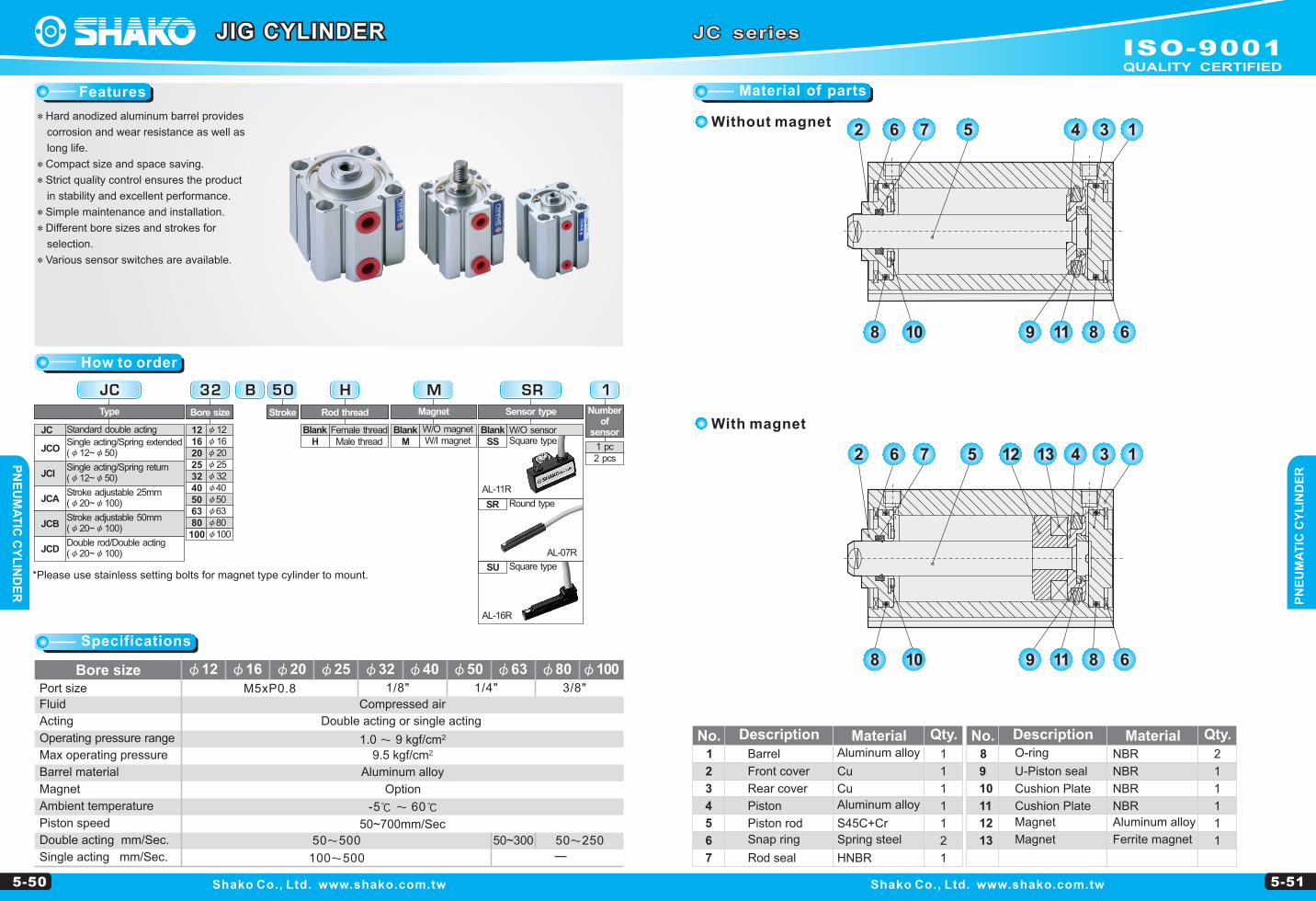
Features How to order Dimensions PNEUMATIC CYLINDER PNEUMATIC CYLINDER 5-50 5-51 JC series φ12 1/8" 3/8" -5℃ 60 ℃ φ40 φ50 φ63 φ80 φ100 1/4" φ32 φ16 φ20 φ25 M5xP0.8 2 1.0 9 kgf/cm 100500 50500 50~300 50250 2 9.5 kgf/cm Shako Co., Ltd. www.shako.com.tw Shako Co., Ltd. www.shako.com.tw JIG CYLINDER *Hard anodized aluminum barrel provides corrosion and wear resistance as well as long life. *Compact size and space saving. *Strict quality control ensures the product in stability and excellent performance. *Simple maintenance and installation. *Different bore sizes and strokes for selection. *Various sensor switches are available. JC JC JCO JCI JCA JCB JCD Standard double acting Double rod/Double acting (φ20~φ100) Stroke adjustable 25mm (φ20~φ100) Single acting/Spring extended (φ12~φ50) Single acting/Spring return (φ12~φ50) Stroke adjustable 50mm (φ20~φ100) Type B 32 32 φ32 φ40 φ50 φ63 φ80 φ100 40 50 63 80 100 25 φ25 20 φ20 16 φ16 12 φ12 Bore size 50 Stroke 1 Number of sensor 1 pc 2 pcs SR SS SR SU AL-11R AL-07R AL-16R Sensor type W/O sensor Square type Round type Blank M M Magnet W/O magnet W/I magnet Blank H H Rod thread Female thread Male thread Blank Bore size Port size Fluid Acting Operating pressure range Max operating pressure Barrel material Magnet Ambient temperature Piston speed Double acting mm/Sec. Single acting mm/Sec. 50~700mm/Sec Option Aluminum alloy Double acting or single acting Compressed air Material of parts - *Please use stainless setting bolts for magnet type cylinder to mount. Square type 1 2 3 4 5 6 7 Without magnet With magnet No. Description Material Qty. Front cover Piston rod Barrel Piston Rod seal Snap ring Cu S45C+Cr Aluminum alloy Aluminum alloy HNBR Spring steel 2 6 7 5 4 3 1 8 10 9 11 8 6 2 6 7 5 4 3 1 13 12 8 10 9 11 8 6 Rear cover Cu 8 9 10 11 12 13 No. Description Material Qty. O-ring NBR Cushion Plate Magnet U-Piston seal NBR NBR NBR Aluminum alloy Magnet Cushion Plate Ferrite magnet 1 1 1 1 1 2 1 2 1 1 1 1 1 Specifications ISO-9001 QUALITY CERTIFIED
Transcript of JIG CYLINDER ISO-9001 - Pneumatic Cylinders ... CYLINDER JC series φ12 φ16 φ20 φ25 φ32 φ40...
Features
How to order
Dimensions
PN
EU
MA
TIC
CY
LIN
DE
RP
NE
UM
AT
IC C
YL
IND
ER
5-50 5-51
JC series
φ121/8" 3/8"
-5℃ � 60℃
φ40 φ50 φ63 φ80 φ1001/4"
φ32φ16 φ20 φ25
M5xP0.8
2 1.0 � 9 kgf/cm
100�500
50�500 50~300 50�250
2 9.5 kgf/cm
Shako Co., Ltd. www.shako.com.tw Shako Co., Ltd. www.shako.com.tw
JIG CYLINDER
*Hard anodized aluminum barrel provides
corrosion and wear resistance as well as
long life.
*Compact size and space saving.
*Strict quality control ensures the product
in stability and excellent performance.
*Simple maintenance and installation.
*Different bore sizes and strokes for
selection.
*Various sensor switches are available.
JC
JC
JCO
JCI
JCA
JCB
JCD
Standard double acting
Double rod/Double acting(φ20~φ100)
Stroke adjustable 25mm(φ20~φ100)
Single acting/Spring extended(φ12~φ50)
Single acting/Spring return(φ12~φ50)
Stroke adjustable 50mm (φ20~φ100)
Type
B32
32 φ32φ40φ50φ63φ80φ100
40506380
100
25 φ2520 φ2016 φ1612 φ12
Bore size
50
Stroke
1
Number of
sensor
1 pc 2 pcs
SR
SS
SR
SU
AL-11R
AL-07R
AL-16R
Sensor type
W/O sensorSquare type
Round type
Blank
M
M
Magnet
W/O magnetW/I magnet
Blank
H
H
Rod thread
Female threadMale thread
Blank
Bore sizePort size
Fluid
Acting
Operating pressure range
Max operating pressure
Barrel material
Magnet
Ambient temperature
Piston speed
Double acting mm/Sec.
Single acting mm/Sec.
50~700mm/Sec
Option
Aluminum alloy
Double acting or single acting
Compressed air
Material of parts
-
*Please use stainless setting bolts for magnet type cylinder to mount.Square type
1
2
3
4
5
6
7
Without magnet
With magnet
No. Description Material Qty.
Front cover
Piston rod
Barrel
Piston
Rod seal
Snap ring
Cu
S45C+Cr
Aluminum alloy
Aluminum alloy
HNBR
Spring steel
2 6 7 5 4 3 1
8 10 9 11 8 6
2 6 7 5 4 3 11312
8 10 9 11 8 6
Rear cover Cu
8
9
10
11
12
13
No. Description Material Qty.O-ring NBR
Cushion Plate
Magnet
U-Piston seal NBR
NBR
NBR
Aluminum alloy
Magnet
Cushion Plate
Ferrite magnet
1
1
1
1
1
2
1
2
1
1
1
1
1
Specifications
ISO-9001QUALITY CERTIFIED
PN
EU
MA
TIC
CY
LIN
DE
RP
NE
UM
AT
IC C
YL
IND
ER
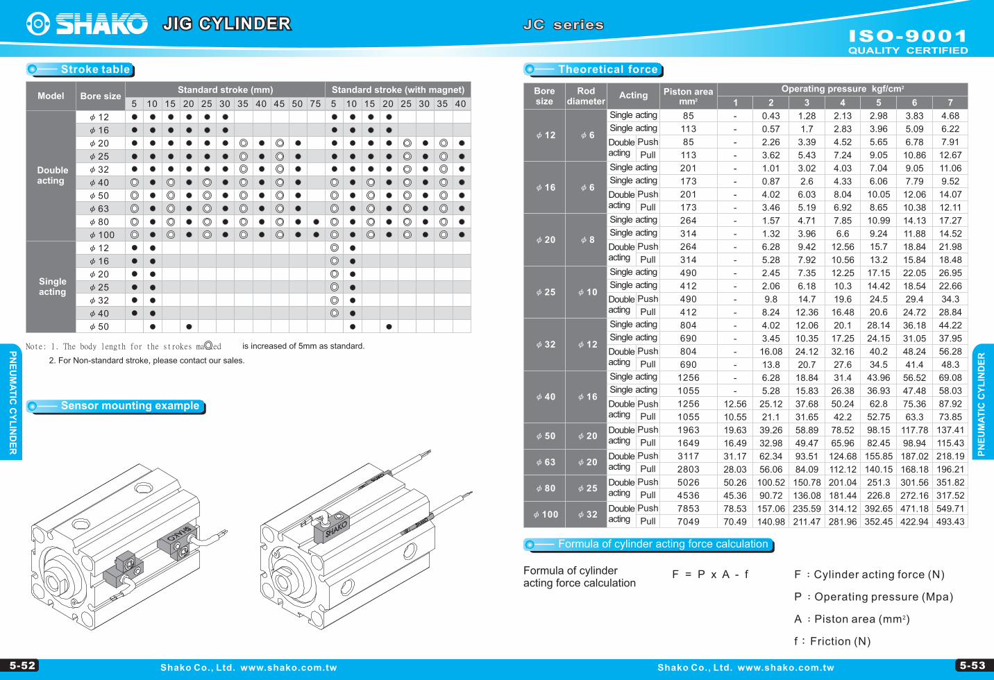
Theoretical forceStroke table
5-52 5-53
2 mm
φ12
φ16
φ20
φ25
φ32
φ40
φ50
φ63
φ80
φ100
φ6
φ8
φ10
φ12
φ16
φ20
φ20
φ25
φ32
1 2 3 4 5 6 7
85
113
85
113
201
173
201
173
264
314
264
314
490
412
490
412
804
690
804
690
1256
1055
1256
1055
1963
1649
3117
2803
5026
4536
7853
7049
-
-
-
-
-
-
-
-
-
-
-
-
-
-
-
-
-
-
-
-
-
-
12.56
10.55
19.63
16.49
31.17
28.03
50.26
45.36
78.53
70.49
0.43
0.57
2.26
3.62
1.01
0.87
4.02
3.46
1.57
1.32
6.28
5.28
2.45
2.06
9.8
8.24
4.02
3.45
16.08
13.8
6.28
5.28
25.12
21.1
39.26
32.98
62.34
56.06
100.52
90.72
157.06
140.98
1.28
1.7
3.39
5.43
3.02
2.6
6.03
5.19
4.71
3.96
9.42
7.92
7.35
6.18
14.7
12.36
12.06
10.35
24.12
20.7
18.84
15.83
37.68
31.65
58.89
49.47
93.51
84.09
150.78
136.08
235.59
211.47
2.13
2.83
4.52
7.24
4.03
4.33
8.04
6.92
7.85
6.6
12.56
10.56
12.25
10.3
19.6
16.48
20.1
17.25
32.16
27.6
31.4
26.38
50.24
42.2
78.52
65.96
124.68
112.12
201.04
181.44
314.12
281.96
2.98
3.96
5.65
9.05
7.04
6.06
10.05
8.65
10.99
9.24
15.7
13.2
17.15
14.42
24.5
20.6
28.14
24.15
40.2
34.5
43.96
36.93
62.8
52.75
98.15
82.45
155.85
140.15
251.3
226.8
392.65
352.45
3.83
5.09
6.78
10.86
9.05
7.79
12.06
10.38
14.13
11.88
18.84
15.84
22.05
18.54
29.4
24.72
36.18
31.05
48.24
41.4
56.52
47.48
75.36
63.3
117.78
98.94
187.02
168.18
301.56
272.16
471.18
422.94
4.68
6.22
7.91
12.67
11.06
9.52
14.07
12.11
17.27
14.52
21.98
18.48
26.95
22.66
34.3
28.84
44.22
37.95
56.28
48.3
69.08
58.03
87.92
73.85
137.41
115.43
218.19
196.21
351.82
317.52
549.71
493.43
F = P x A - f
F:Cylinder acting force (N)
P:Operating pressure (Mpa)
2A:Piston area (mm )
f:Friction (N)
Shako Co., Ltd. www.shako.com.tw Shako Co., Ltd. www.shako.com.tw
Note: 1. The body length for the strokes marked is increased of 5mm as standard.
2. For Non-standard stroke, please contact our sales.
Sensor mounting example
Bore size
Rod diameter
Acting Piston area2Operating pressure kgf/cm
Single acting
Double acting
Push
Pull
Single acting
Single acting
Single acting
Single acting
Single acting
Double acting
Double acting
Double acting
Push
Pull
Pull
Push
Pull
Push
Single acting
Single acting
Single acting
Single acting
Double acting
Double acting
Double acting
Double acting
Double acting
Double acting
Single acting
Single acting
Pull
Push
Pull
Push
Pull
Push
Pull
Push
Pull
Push
Pull
Push
Formula of cylinder acting force calculation
Formula of cylinder acting force calculation
JC seriesJIG CYLINDER
φ12
φ16
φ20
φ25
φ32
φ40
φ50
φ63
φ80
φ100
φ12
φ16
φ20
φ25
φ32
φ40
φ50
5 10 15 20 25 30 35 40 45 50 75 5 10 15 20 25 30 35 40 45 50 75
Double acting
Single acting
Model Bore size Standard stroke (mm)
φ6
5 15 25 5 10 20 30 35 40 45 50 75 10 15 20 25 30 35 40
Standard stroke (with magnet)
ISO-9001QUALITY CERTIFIED
PN
EU
MA
TIC
CY
LIN
DE
RP
NE
UM
AT
IC C
YL
IND
ER
5-54 5-55
φ12
φ16
φ20
φ25
A B1 C
22
24
25
27
5
5.5
5.5
6
M5xP0.8
M5xP0.8
M5xP0.8
M5xP0.8
17
18.5
19.5
21
32
34
35
37
5
5.5
5.5
6
27
28.5
29.5
31
-
-
-
-
4
4
4
4
1
1.5
1.5
2
M3xP0.5xL6
M3xP0.5xL6
M4xP0.7xL8
M5xP0.8xL10
φ11
φ11
φ15
φ17
3
3
3
3
6.5
7
7.5
7
C B1 A D F G K1 L M N1 O
P3 P4 R S T1 T2 U V W X YP1
φ12
φ16
φ20
φ25
12
12
14
15
4.5
4.5
4.5
5.5
-
-
-
-
25
29
34
40
16.3
19.8
24
28
23
28
-
-
R16
R19
R22
R25
φ6
φ6
φ8
φ10
5
5
6
8
-
-
-
-
-
-
-
-
φ12
MH
J
I
K
B
E G
K14 - P1
U
ST1XY
D
RS
T1
U
K12-P1
T2
S T1
S
T1
φ20 ~φ25
A+Stroke
P3P3
P4P4
M
F G
N1 2-O
C+StrokeB1
φL
W
φ16
2-P1
S T1
S
T1
K1
U
4-P1 K1
S T1
S
T1U
JC Standard double acting JC Standard double acting
JC series
Shako Co., Ltd. www.shako.com.tw Shako Co., Ltd. www.shako.com.tw
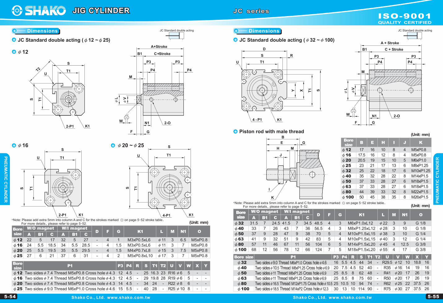
JC Standard double acting (φ12 ~φ25)
Bore size
(Unit: mm)
Bore size
W/I magnetW/O magnet
JC Standard double acting (φ32 ~φ100)
φ32
φ40
φ50
φ63
φ80
φ100
A B1 C
31.5
33
37
41
57
68
7
7
9
9
11
12
G 1/8
G 1/8
G 1/4
G 1/4
G 3/8
G 3/8
24.5
26
28
32
46
56
41.5
43
47
51
67
78
7
7
9
9
11
12
34.5
36
38
42
56
66
48.5
56.5
70
83
104
124
4
4
5
5
6
7
3
3
4
4
5
5
M6xP1.0xL12
M8xP1.25xL12
M10xP1.5xL15
M10xP1.5xL15
M14xP1.5xL20
M18xP1.5xL20
φ22
φ28
φ38
φ40
φ45
φ55
3
3
3
3
4
4
9
10
10
12
12.5
17
C B1 A D F G K1 L M N1 O
Bore size
W/O magnet W/I magnet
(Unit: mm)
2-O
A + Stroke
C + StrokeB1
F G
M
N1
P3
P4
P3
P4
φL
φV
W
φ12
φ16
φ20
φ25
φ32
φ40
φ50
φ63
φ80
φ100
B E H I J K
17
17.5
20.5
23
25
35
37
37
44
50
16
16
19
21
22
32
33
33
39
45
10
12
15
17
18
28
28
28
33
38
8
8
10
13
17
22
27
27
32
35
4
4
5
6
6
8
6
6
8
8
M5xP0.8
M5xP0.8
M6xP1.0
M8xP1.25
M10xP1.25
M14xP1.5
M18xP1.5
M18xP1.5
M22xP1.5
M26xP1.5
Bore size
(Unit: mm)Piston rod with male thread
Bore size
16
20
25
25
25
30
5.5
7.5
8.5
8.5
10.5
13
4.5
4.5
8
8
10
10
44
52
62
75
94
114
34
40
48
60
74
90
-
-
-
-
-
-
P3 P4 R S T1 T2 U V W X YP1
φ32
φ40
φ50
φ63
φ80
φ100
R29.5
R35
R41
R50
R62
R75
φ12
φ16
φ20
φ20
φ25
φ30
10
14
17
17
22
27
18.8
19
26
26
37.5
37.5
16
16
19
19
26
26
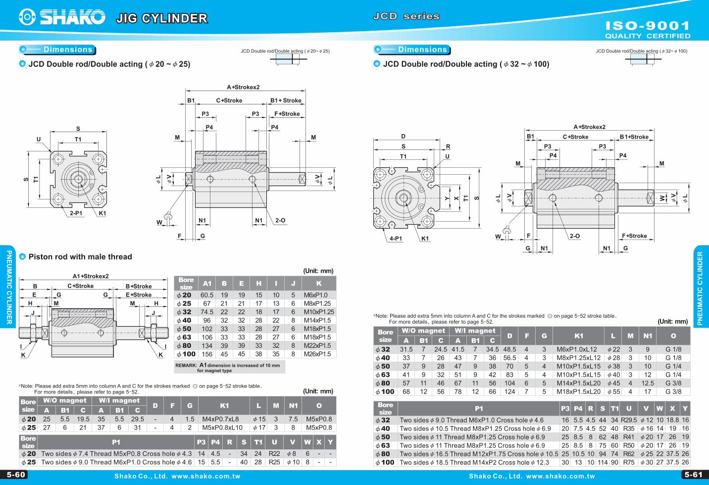
Two sidesφ9.0 Thread M6xP1.0 Cross holeφ4.6Two sidesφ10.5 Thread M8xP1.25 Cross holeφ6.9Two sidesφ11 Thread M8xP1.25 Cross holeφ6.9Two sidesφ11 Thread M8xP1.25 Cross holeφ6.9Two sidesφ16.5 Thread M12xP1.75 Cross holeφ10.5Two sidesφ18.5 Thread M14xP2 Cross holeφ12.3
Bore size
Two sidesφ7.4 Thread M5xP0.8 Cross holeφ4.3
Two sidesφ7.4 Thread M5xP0.8 Cross holeφ4.3
Two sidesφ7.4 Thread M5xP0.8 Cross holeφ4.3
Two sidesφ9.0 Thread M6xP1.0 Cross holeφ4.6
JIG CYLINDER
φV
*Note: Please add extra 5mm into column A and C for the strokes marked ◎ on page 5-52 stroke table. For more details, please refer to page 5-52.
*Note: Please add extra 5mm into column A and C for the strokes marked ◎ on page 5-52 stroke table. For more details, please refer to page 5-52.
DimensionsDimensions
ISO-9001QUALITY CERTIFIED
PN
EU
MA
TIC
CY
LIN
DE
RP
NE
UM
AT
IC C
YL
IND
ER
U V
R16
R19
R22
R25
φ6
φ6
φ8
φ10
JCO Single acting/Spring extended (φ12~φ50)
5-56 5-57
W X YP1
φ12
φ16
φ20
φ25
P3 P4 R S
12
12
14
15
4.5
4.5
4.5
5.5
-
-
-
-
25
29
34
40
T1 T2
16.3
19.8
24
28
23
28
-
-
5
5
6
8
-
-
-
-
-
-
-
-
Two sidesφ7.4 Thread M5xP0.8 Cross holeφ4.3
Two sidesφ7.4 Thread M5xP0.8 Cross holeφ4.3
Two sidesφ7.4 Thread M5xP0.8 Cross holeφ4.3
Two sidesφ9.0 Thread M6xP1.0 Cross holeφ4.6
A B1 C
G 1/8
G 1/8
G 1/4
48.5
56.5
70
4
4
5
3
3
4
M6xP1.0xL12
M8xP1.25xL12
M10xP1.5xL15
φ22
φ28
φ38
3
3
3
9
10
10
C B1 A D F G K1 L M N1 O
41.5
43
47
7
7
9
34.5
36
38
51.5
53
57
7
7
9
44.5
46
48
P1
φ32
φ40
φ50
Two sidesφ9.0 Thread M6xP1.0 Cross holeφ4.6
Two sidesφ10.5 Thread M8xP1.25 Cross holeφ6.9
Two sidesφ11 Thread M8xP1.25 Cross holeφ6.9
W X Y
10
14
17
16
16
19
19.5
19.5
26.5
φ12
φ16
φ20
φ25
φ32
φ40
φ50
B E H I J K
17
17.5
20.5
23
25
35
37
16
16
19
21
22
32
33
10
12
15
17
18
28
28
8
8
10
13
17
22
27
4
4
5
6
6
8
6
M5xP0.8
M5xP0.8
M6xP1.0
M8xP1.25
M10xP1.25
M14xP1.5
M18xP1.5
K14 - P1
U
ST1XY
D
RS
T1
2-O
A+Strokex2
C+StrokeB1+Stroke
F+Stroke G
M
N1
P3
P4
P3
P4
φL
φV
I
K
GE+Stroke
B+Stroke
J
H M
φ12
φ16
φ20
φ25
A B1 C
M5xP0.8
M5xP0.8
M5xP0.8
M5xP0.8
-
-
-
-
4
4
4
4
1
1.5
1.5
2
M3xP0.5xL6
M3xP0.5xL6
M4xP0.7xL8
M5xP0.8xL10
φ11
φ11
φ15
φ17
3
3
3
3
6.5
7
7.5
8
C B1 A D F G K1 L M N1 O
22
24
25
27
5
5.5
5.5
6
27
18.5
19.5
21
32
34
35
37
5
5.5
5.5
6
37
28.5
29.5
31
4-P1 K1
T1
S
T1S
2-P1
φ12
U
K12-P1
T2
S T1
S
T1
φ16
A+Strokex2
C+StrokeB1+Stroke
P3P3
P4P4M
F+Stroke G
N1 2-O
φL
W
UU
W
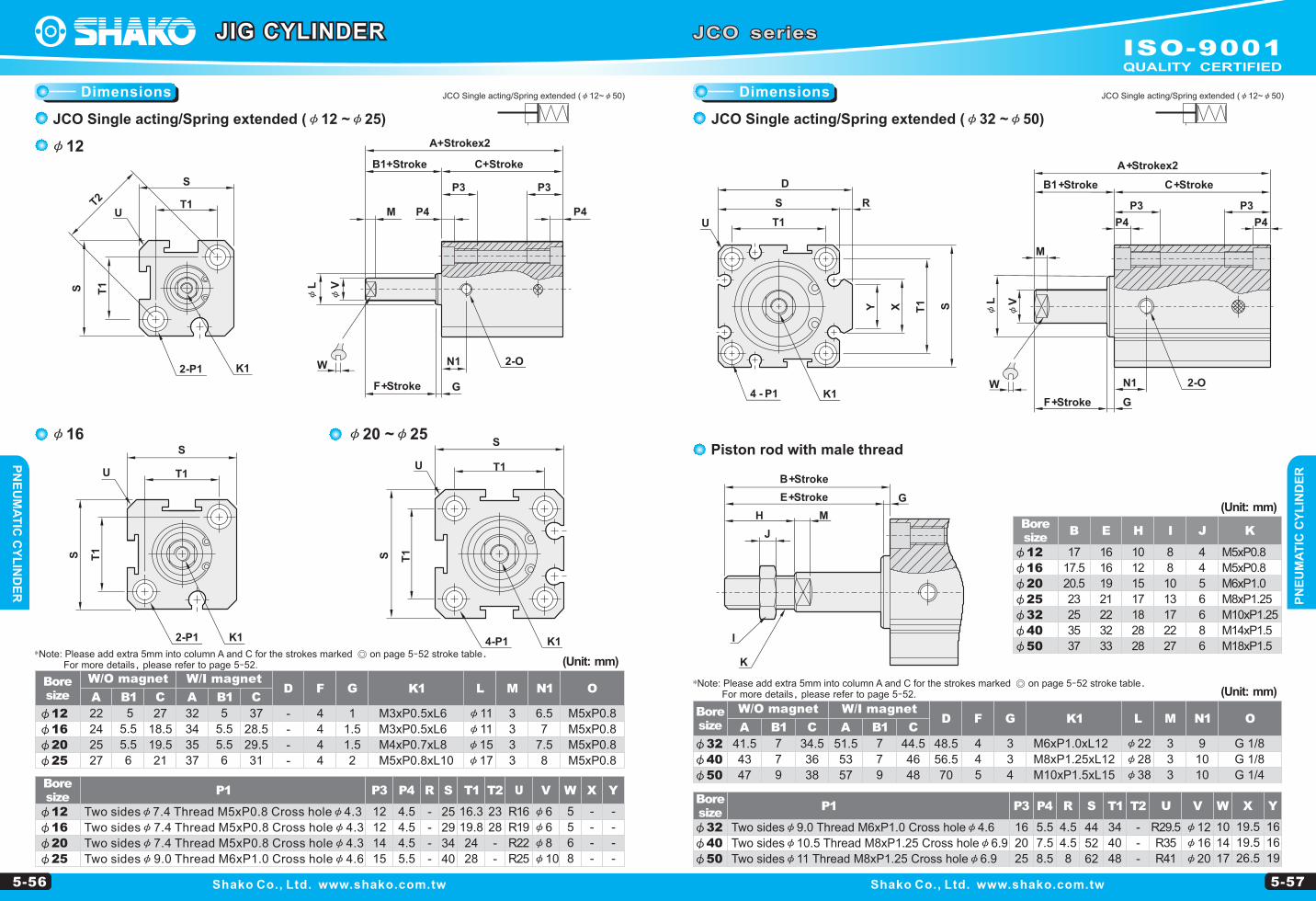
JCO Single acting/Spring extended (φ12~φ50)
JCO series
Shako Co., Ltd. www.shako.com.tw Shako Co., Ltd. www.shako.com.tw
Bore size
W/I magnetW/O magnet
Bore size
(Unit: mm)
Bore size
W/O magnet W/I magnet
(Unit: mm)
Bore size
(Unit: mm)
Piston rod with male thread
Bore size
JCO Single acting/Spring extended (φ12 ~φ25) JCO Single acting/Spring extended (φ32 ~φ50)
U V
R29.5
R35
R41
φ12
φ16
φ20
P3 P4 R S T1 T2
16
20
25
5.5
7.5
8.5
4.5
4.5
8
44
52
62
34
40
48
-
-
-
JIG CYLINDER
S T1
T1
S
φ32
φ40
φ50
K1
φV
φ20 ~φ25
*Note: Please add extra 5mm into column A and C for the strokes marked ◎ on page 5-52 stroke table. For more details, please refer to page 5-52.
*Note: Please add extra 5mm into column A and C for the strokes marked ◎ on page 5-52 stroke table. For more details, please refer to page 5-52.
DimensionsDimensions
ISO-9001QUALITY CERTIFIED
PN
EU
MA
TIC
CY
LIN
DE
RP
NE
UM
AT
IC C
YL
IND
ER
T1 T2 U V
34
40
48
-
-
-
R29.5
R35
R41
φ12
φ16
φ20
R S
-
-
-
-
25
29
34
40
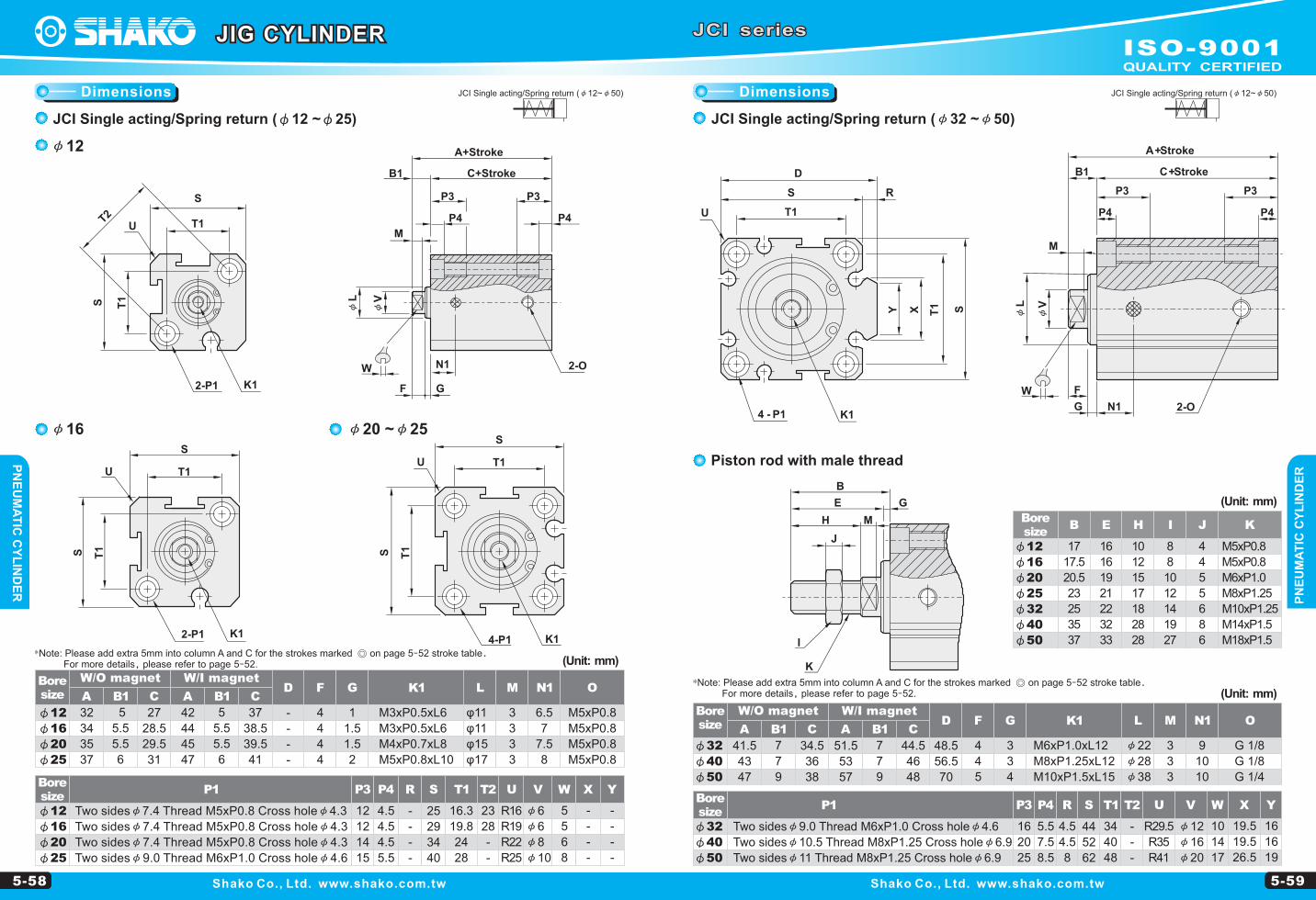
JCI Single acting/Spring return (φ12~φ50)
5-58 5-59
P1
φ12
φ16
φ20
φ25
P3 P4
12
12
14
15
4.5
4.5
4.5
5.5
V W X YU
R16
R19
R22
R25
φ6
φ6
φ8
φ10
5
5
6
8
-
-
-
-
-
-
-
-
φ12
φ16
φ20
φ25
A B1 C
M5xP0.8
M5xP0.8
M5xP0.8
M5xP0.8
-
-
-
-
4
4
4
4
1
1.5
1.5
2
M3xP0.5xL6
M3xP0.5xL6
M4xP0.7xL8
M5xP0.8xL10
φ11
φ11
φ15
φ17
3
3
3
3
6.5
7
7.5
8
C B1 A D F G K1 L M N1 O
32
34
35
37
5
5.5
5.5
6
27
28.5
29.5
31
42
44
45
47
5
5.5
5.5
6
37
38.5
39.5
41
P1
φ32
φ40
φ50
R S
4.5
4.5
8
44
52
62
W X Y
10
14
17
16
16
19
19.5
19.5
26.5
φ32
φ40
φ50
A B1 C
G 1/8
G 1/8
G 1/4
48.5
56.5
70
4
4
5
3
3
4
M6xP1.0xL12
M8xP1.25xL12
M10xP1.5xL15
φ22
φ28
φ38
3
3
3
9
10
10
C B1 A D F G K1 L M N1 O
41.5
43
47
7
7
9
34.5
36
38
51.5
53
57
7
7
9
44.5
46
48
φ12
φ16
φ20
φ25
φ32
φ40
φ50
B E H I J K
17
17.5
20.5
23
25
35
37
16
16
19
21
22
32
33
10
12
15
17
18
28
28
8
8
10
12
14
19
27
4
4
5
5
6
8
6
M5xP0.8
M5xP0.8
M6xP1.0
M8xP1.25
M10xP1.25
M14xP1.5
M18xP1.5I
K
GE
B
J
H M
φ16
φ12
φ20 ~φ25
φV
W
φL
φV
W
JCI Single acting/Spring return (φ12~φ50)
JCI series
Shako Co., Ltd. www.shako.com.tw Shako Co., Ltd. www.shako.com.tw
Bore size
W/O magnet W/I magnet
Bore size
(Unit: mm)
Bore size
(Unit: mm)
Piston rod with male thread
Bore size
W/I magnetW/O magnet
Bore size
(Unit: mm)
JCI Single acting/Spring return (φ12 ~φ25)
T1 T2
16.3
19.8
24
28
23
28
-
-
Two sidesφ7.4 Thread M5xP0.8 Cross holeφ4.3
Two sidesφ7.4 Thread M5xP0.8 Cross holeφ4.3
Two sidesφ7.4 Thread M5xP0.8 Cross holeφ4.3
Two sidesφ9.0 Thread M6xP1.0 Cross holeφ4.6
JCI Single acting/Spring return (φ32 ~φ50)
P3 P4
16
20
25
5.5
7.5
8.5
Two sidesφ9.0 Thread M6xP1.0 Cross holeφ4.6
Two sidesφ10.5 Thread M8xP1.25 Cross holeφ6.9
Two sidesφ11 Thread M8xP1.25 Cross holeφ6.9
JIG CYLINDER
T2T1
T1
U
K12-P1
S
S
N1
A+Stroke
C+Stroke
P3P3
P4P4
GF
2-O
U T1
SU T1
S
T1S T1S
K12-P1 K14-P1
U
D
RS
T1
K14 - P12-O
A+Stroke
C+StrokeB1
G
M
N1
P3
P4
P3
P4
F
ST1XY
B1
M
φL
*Note: Please add extra 5mm into column A and C for the strokes marked ◎ on page 5-52 stroke table. For more details, please refer to page 5-52.
*Note: Please add extra 5mm into column A and C for the strokes marked ◎ on page 5-52 stroke table. For more details, please refer to page 5-52.
DimensionsDimensions
ISO-9001QUALITY CERTIFIED
PN
EU
MA
TIC
CY
LIN
DE
RP
NE
UM
AT
IC C
YL
IND
ER
JCD Double rod/Double acting (φ20~φ25)
5-60 5-61
P1
φ32
φ40
φ50
φ63
φ80
φ100
X YV W
φ12
φ16
φ20
φ20
φ25
φ30
10
14
17
17
22
27
18.8
19
26
26
37.5
37.5
16
16
19
19
26
26
φ32
φ40
φ50
φ63
φ80
φ100
A B1 C
G 1/8
G 1/8
G 1/4
G 1/4
G 3/8
G 3/8
M6xP1.0xL12
M8xP1.25xL12
M10xP1.5xL15
M10xP1.5xL15
M14xP1.5xL20
M18xP1.5xL20
φ22
φ28
φ38
φ40
φ45
φ55
3
3
3
3
4
4
9
10
10
12
12.5
17
C B1 A D F G K1 L M N1 O
31.5
33
37
41
57
68
7
7
9
9
11
12
24.5
26
28
32
46
56
41.5
43
47
51
67
78
7
7
9
9
11
12
34.5
36
38
42
56
66
48.5
56.5
70
83
104
124
4
4
5
5
6
7
3
3
4
4
5
5
P1
φ20
φ25
U V W X Y
R22
R25
φ8
φ10
6
8
-
-
-
-
φ20
φ25
A B1 C
M5xP0.8
M5xP0.8
M4xP0.7xL8
M5xP0.8xL10
φ15
φ17
3
3
7.5
8
C B1 A D F G K1 L M N1 O
25
27
5.5
6
19.5
21
35
37
5.5
6
29.5
31
-
-
4
4
1.5
2
φ20
φ25
φ32
φ40
φ50
φ63
φ80
φ100
19
21
22
32
33
33
39
45
15
17
18
28
28
28
33
38
10
13
17
22
27
27
32
35
5
6
6
8
6
6
8
8
M6xP1.0
M8xP1.25
M10xP1.25
M14xP1.5
M18xP1.5
M18xP1.5
M22xP1.5
M26xP1.5
19
21
22
32
33
33
39
45
60.5
67
74.5
96
102
106
134
156
MH
J
I
K
B
E G
M H
B+Stroke
E+StrokeG
I
K
C+Stroke
A1+Strokex2
J
U
A+Strokex2
C+Stroke B1+ Stroke
F+Stroke
φL
φV
φL
φV
W
C+Stroke
A+Strokex2
F+Stroke
B1+Stroke
φL
φV
φL
φV
W
JCD Double rod/Double acting (φ32~φ100)
JCD series
Shako Co., Ltd. www.shako.com.tw Shako Co., Ltd. www.shako.com.tw
Bore size
Bore size
(Unit: mm)
Bore size
(Unit: mm)
W/I magnetW/O magnet
Piston rod with male thread
Bore size
Bore size
W/O magnet W/I magnet
(Unit: mm)
JCD Double rod/Double acting (φ20 ~φ25) JCD Double rod/Double acting (φ32 ~φ100)
B A1 E H I J K
Two sidesφ7.4 Thread M5xP0.8 Cross holeφ4.3
Two sidesφ9.0 Thread M6xP1.0 Cross holeφ4.6
P3 P4 R S T1
14
15
4.5
5.5
-
-
34
40
24
28
U
R29.5
R35
R41
R50
R62
R75
R S T1 P3 P4
16
20
25
25
25
30
5.5
7.5
8.5
8.5
10.5
13
4.5
4.5
8
8
10
10
44
52
62
75
94
114
34
40
48
60
74
90
JIG CYLINDER
Two sidesφ9.0 Thread M6xP1.0 Cross holeφ4.6
Two sidesφ10.5 Thread M8xP1.25 Cross holeφ6.9
Two sidesφ11 Thread M8xP1.25 Cross holeφ6.9
Two sidesφ11 Thread M8xP1.25 Cross holeφ6.9
Two sidesφ16.5 Thread M12xP1.75 Cross holeφ10.5
Two sidesφ18.5 Thread M14xP2 Cross holeφ12.3
REMARK: dimension is increased of 10 mm for magnet type
A1
B1
M
P4
P3
P4
P3
M
D
S
T1
R
U
W
GN1
F 2-O
N1G
4-P1 K1
ST1XY
T1
T1
K12-P1
S
S
N1
P3
P4
GF
2-O
B1
P3
P4
M
N1
M
*Note: Please add extra 5mm into column A and C for the strokes marked ◎ on page 5-52 stroke table. For more details, please refer to page 5-52.
*Note: Please add extra 5mm into column A and C for the strokes marked ◎ on page 5-52 stroke table. For more details, please refer to page 5-52.
DimensionsDimensions
ISO-9001QUALITY CERTIFIED
PN
EU
MA
TIC
CY
LIN
DE
RP
NE
UM
AT
IC C
YL
IND
ER
5-62 5-63
P1
φ32
φ40
φ50
φ63
φ80
φ100
φ32
φ40
φ50
φ63
φ80
φ100
A B1 C
22
28
38
40
45
55
3
3
3
3
4
4
9
10
10
12
12.5
17
C B1 A D F G J1
M6xP1.0xL12
M8xP1.25xL12
M10xP1.5xL15
M10xP1.5xL15
M14xP1.5xL20
M18xP1.5xL20
K1 L M N1 O
69.5
71
82
86
109
121
7
7
9
9
11
12
24.5
26
28
32
46
56
79.5
81
92
96
119
131
7
7
9
9
11
12
34.5
36
38
42
56
66
48.5
56.5
70
83
104
124
4
4
5
5
6
7
3
3
4
4
5
5
P1
φ20
φ25
φ20
φ25
A B1 C
M5xP0.8
M5xP0.8
φ15
φ17
3
3
7.5
8
C B1 A D F G
M4xP0.7xL8
M5xP0.8xL10
K1 L M N1 O
59.5
63
5.5
6
19.5
21
69.5
73
5.5
6
29.5
31
-
-
4
4
1.5
2
J1
5
5
6
7
8
8
10
10
φ20
φ25
φ32
φ40
φ50
φ63
φ80
φ100
B A1 E H I J K
19
21
22
32
33
33
39
45
15
17
18
28
28
28
33
38
M6xP1.0
M8xP1.25
M10xP1.25
M14xP1.5
M18xP1.5
M18xP1.5
M22xP1.5
M26xP1.5
20.5
23
25
35
37
37
44
50
74.5
80
87.5
99
110
114
142
159
C+Stroke
Q+Adjustable stroke
G+Stroke
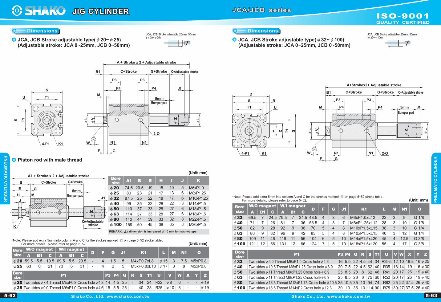
A1 + Stroke x 2 + Adjustable stroke
4-P1
T1
S
T1S
K1
U
C+Stroke
A + Stroke x 2 + Adjustable stroke
B1 Q+Adjustable strokeG+Stroke
X V W U
R29.5
R35
R41
R50
R62
R75
Q
22
22
28
28
35
35
S T1 R
4.5
4.5
8
8
10
10
44
52
62
75
94
114
34
40
48
60
74
90
12
16
20
20
25
30
10
14
17
17
22
27
18.8
19
26
26
37.5
37.5
16
16
19
19
26
26
Y
K1
U
4-P1
T1
S
D
R
T1 SY X
Q+Adjustable stroke
JCA, JCB Stroke adjustable 25mm, 50mm(φ20~φ25)
JCA/JCB series
Shako Co., Ltd. www.shako.com.tw Shako Co., Ltd. www.shako.com.tw
Bore size
Bore size
W/O magnet W/I magnet
(Unit: mm)
(Unit: mm)
Bore size
Bore size
W/I magnetW/O magnet
Bore size
(Unit: mm)
JIG CYLINDER
JCA, JCB Stroke adjustable type(φ20~φ25)(Adjustable stroke: JCA 0~25mm, JCB 0~50mm)
Piston rod with male thread
JCA, JCB Stroke adjustable 25mm, 50mm(φ32~φ100)
JCA, JCB Stroke adjustable type(φ32~φ100)(Adjustable stroke: JCA 0~25mm, JCB 0~50mm)
P3 P4
16
20
25
25
25
30
5.5
7.5
8.5
8.5
10.5
13
Two sidesφ9.0 Thread M6xP1.0 Cross holeφ4.6
Two sidesφ10.5 Thread M8xP1.25 Cross holeφ6.9
Two sidesφ11 Thread M8xP1.25 Cross holeφ6.9
Two sidesφ11 Thread M8xP1.25 Cross holeφ6.9
Two sidesφ16.5 Thread M12xP1.75 Cross holeφ10.5
Two sidesφ18.5 Thread M14xP2 Cross holeφ12.3
Two sidesφ7.4 Thread M5xP0.8 Cross holeφ4.3
Two sidesφ9.0 Thread M6xP1.0 Cross holeφ4.6
10
13
17
22
27
27
32
35
5
6
6
8
6
6
8
8
G 1/8
G 1/8
G 1/4
G 1/4
G 3/8
G 3/8
2-O
G+Stroke
J1
C+StrokeB1
M
F
P4P4
P3 P3
N1
G
N1W
5mm
A+Stroke x 2 + Adjustable stroke
MH
J
I
K
B
E G
J1
5mm
2-O
P3
M
P4
N1
GF
P4
P3
N1W
J1
5mm
Bumper pad
Bumper pad
Bumper pad
REMARK: dimension is increased of 10 mm for magnet typeA1
U V W X Y
R22
R25
φ8
φ10
6
8
-
-
-
-
P3 P4 Q
14
15
4.5
5.5
25
25
R S T1
-
-
34
40
24
28
Z
φ19
φ19
φ25
φ30
φ40
φ40
φ40
φ40
Z
φL
φV
φL
φL
φV
φL
*Note: Please add extra 5mm into column A and C for the strokes marked ◎ on page 5-52 stroke table. For more details, please refer to page 5-52.
*Note: Please add extra 5mm into column A and C for the strokes marked ◎ on page 5-52 stroke table. For more details, please refer to page 5-52.
DimensionsDimensions
ISO-9001QUALITY CERTIFIED