iTEMP TMT162 Technical Information - portal.endress.com · –PROFIBUS® PA Profile 3.02 ... drift...
24
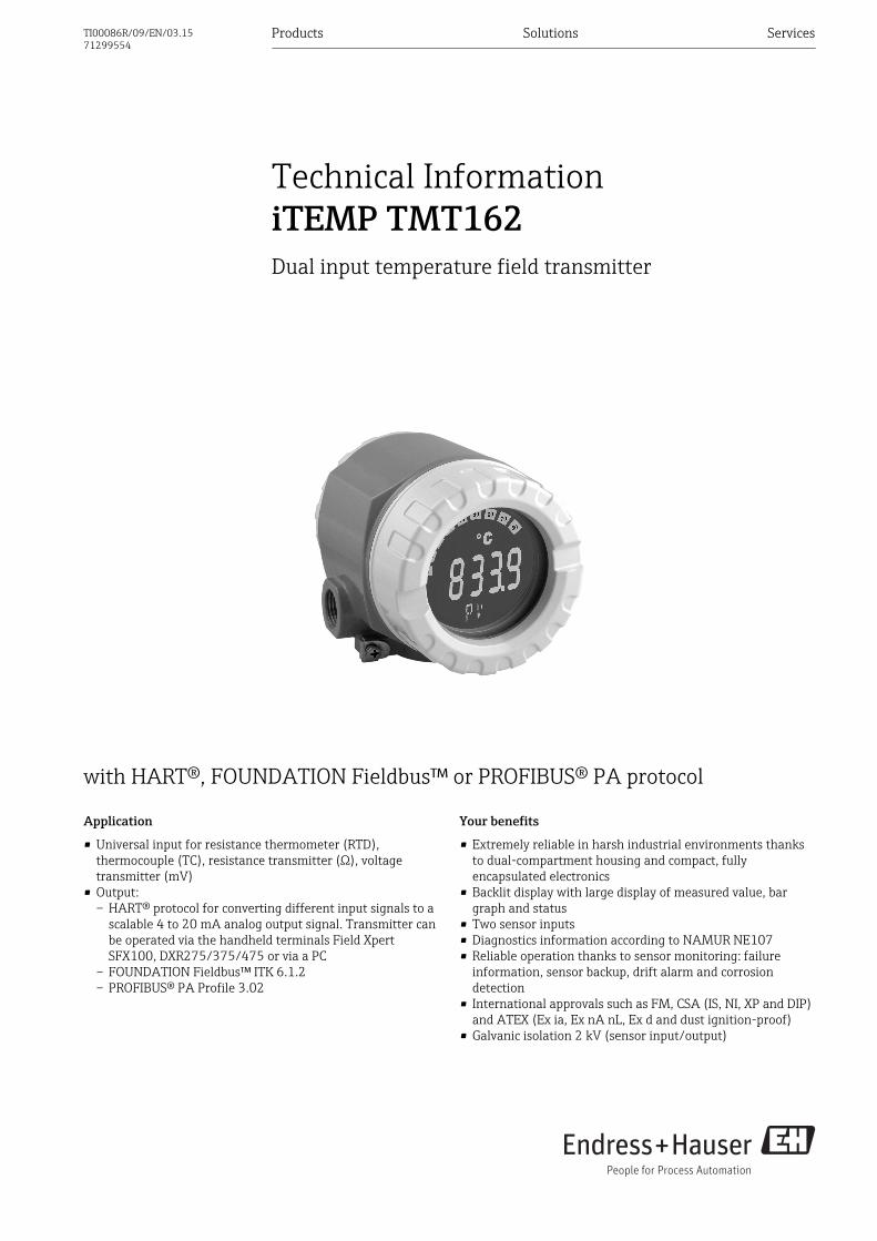
with HART®, FOUNDATION Fieldbus™ or PROFIBUS® PA protocol Application • Universal input for resistance thermometer (RTD), thermocouple (TC), resistance transmitter (Ω), voltage transmitter (mV) • Output: – HART® protocol for converting different input signals to a scalable 4 to 20 mA analog output signal. Transmitter can be operated via the handheld terminals Field Xpert SFX100, DXR275/375/475 or via a PC – FOUNDATION Fieldbus™ ITK 6.1.2 – PROFIBUS® PA Profile 3.02 Your benefits • Extremely reliable in harsh industrial environments thanks to dual-compartment housing and compact, fully encapsulated electronics • Backlit display with large display of measured value, bar graph and status • Two sensor inputs • Diagnostics information according to NAMUR NE107 • Reliable operation thanks to sensor monitoring: failure information, sensor backup, drift alarm and corrosion detection • International approvals such as FM, CSA (IS, NI, XP and DIP) and ATEX (Ex ia, Ex nA nL, Ex d and dust ignition-proof) • Galvanic isolation 2 kV (sensor input/output) Products Solutions Services Technical Information iTEMP TMT162 Dual input temperature field transmitter TI00086R/09/EN/03.15 71299554
Transcript of iTEMP TMT162 Technical Information - portal.endress.com · –PROFIBUS® PA Profile 3.02 ... drift...
with HART®, FOUNDATION Fieldbus™ or PROFIBUS® PA protocol
Application
• Universal input for resistance thermometer (RTD),thermocouple (TC), resistance transmitter (Ω), voltagetransmitter (mV)
• Output:– HART® protocol for converting different input signals to a
scalable 4 to 20 mA analog output signal. Transmitter canbe operated via the handheld terminals Field XpertSFX100, DXR275/375/475 or via a PC
– FOUNDATION Fieldbus™ ITK 6.1.2– PROFIBUS® PA Profile 3.02
Your benefits
• Extremely reliable in harsh industrial environments thanksto dual-compartment housing and compact, fullyencapsulated electronics
• Backlit display with large display of measured value, bargraph and status
• Two sensor inputs• Diagnostics information according to NAMUR NE107• Reliable operation thanks to sensor monitoring: failure
information, sensor backup, drift alarm and corrosiondetection
• International approvals such as FM, CSA (IS, NI, XP and DIP)and ATEX (Ex ia, Ex nA nL, Ex d and dust ignition-proof)
• Galvanic isolation 2 kV (sensor input/output)
Products Solutions Services
Technical InformationiTEMP TMT162Dual input temperature field transmitter
TI00086R/09/EN/03.1571299554
iTEMP TMT162
2 Endress+Hauser
Function and system design
Measuring principle Electronic monitoring, conversion and display of input signals used in industrial temperaturemeasurement.
Measuring system
RTD/TC
1 x RTD/TC /
2 x RTD/TC
RTD/TC
°C
°C °C
1
2 3
A0026076
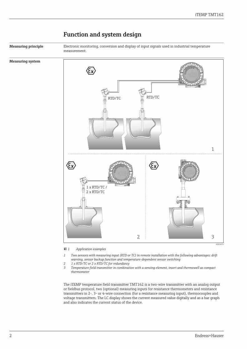
1 Application examples
1 Two sensors with measuring input (RTD or TC) in remote installation with the following advantages: driftwarning, sensor backup function and temperature-dependent sensor switching
2 1 x RTD/TC or 2 x RTD/TC for redundancy3 Temperature field transmitter in combination with a sensing element, insert and thermowell as compact
thermometer
The iTEMP temperature field transmitter TMT162 is a two-wire transmitter with an analog outputor fieldbus protocol, two (optional) measuring inputs for resistance thermometers and resistancetransmitters in 2-, 3- or 4-wire connection (for a resistance measuring input), thermocouples andvoltage transmitters. The LC display shows the current measured value digitally and as a bar graphand also indicates the current status of the device.
iTEMP TMT162
Endress+Hauser 3
Standard diagnostic functions• Cable open circuit, short-circuit• Incorrect wiring• Internal device errors• Overrange/underrange detection• Ambient temperature out-of-range detectionCorrosion detection as per NAMUR NE89Corrosion of the sensor connection cables can cause incorrect measured value readings. The fieldtransmitter offers the possibility of detecting corrosion on thermocouples and resistancethermometers with a 4-wire connection before measured value corruption occurs. The transmitterprevents incorrect readings of measured values and can issue a warning on the display as well asthrough the HART® or fieldbus protocol if wire resistance values exceed plausible limits.Low voltage detection for HART® communicationThe low voltage detection function prevents the device from continuously outputting an incorrectanalog output value (i.e. due to a damaged or incorrect power supply or due to a damaged signalcable). If the supply voltage drops below the required value, the analog output value drops to <3.6 mA for approx. 3 s. An error message is displayed. The device then tries to output the normalanalog output value again. If the supply voltage is still too low, the analog output value drops againto < 3.6 mA.Optional dual input functionsThese functions increase the reliability and availability of the process values:• Sensor backup : If sensor 1 fails, the output signal is switched without interruption to the
measured value of sensor 2.• Temperature-dependent sensor switching: The measured value is recorded by sensor 1 or 2
depending on the process temperature.• Sensor drift detection: If both measured values of sensor 1 and 2 deviate from a specified value, a
drift warning or alarm is output.
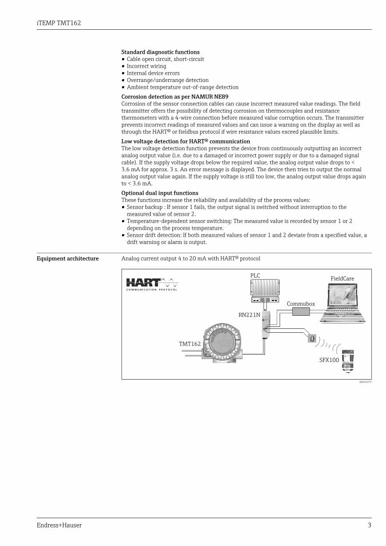
Equipment architecture Analog current output 4 to 20 mA with HART® protocol
TMT162
Commubox
RN221N
PLC
°C
SFX100
FieldCare
A0014375
iTEMP TMT162
4 Endress+Hauser
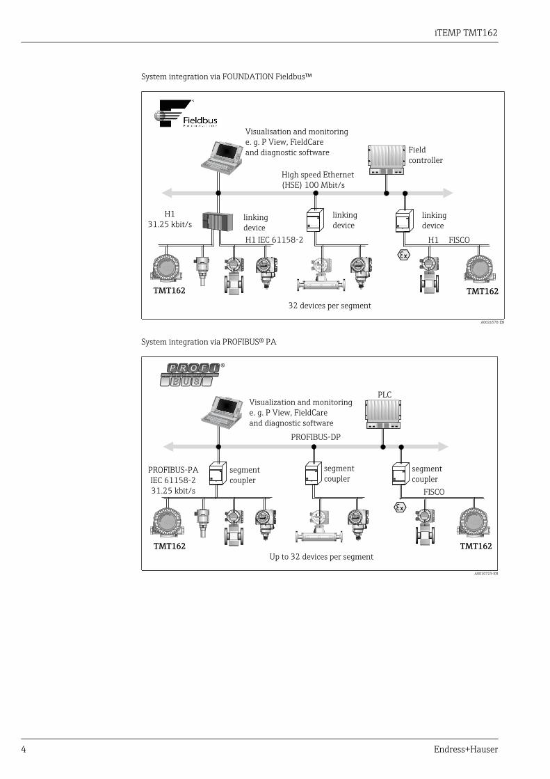
System integration via FOUNDATION Fieldbus™
0 - 10 bar 0 - 10 bar
°C
TMT162
°C
TMT162
Visualisation and monitoring
e. g. P View, FieldCare
and diagnostic software
High speed Ethernet
(HSE) 100 Mbit/s
32 devices per segment
Field
controller
linking
deviceENDRESS + HAUSER ENDRESS + HAUSER
linking
devicelinking
device
H1
31.25 kbit/s
H1 IEC 61158-2 H1 FISCO
A0026578-EN
System integration via PROFIBUS® PA
0 - 10 bar 0 - 10 bar
PROFIBUS-DP
P R O F I
B U S
P R O C E S S F I E L D B U S
®
PROFIBUS-PA
IEC 61158-2
31.25 kbit/s
°C
TMT162
°C
TMT162
Visualization and monitoring
e. g. P View, FieldCare
and diagnostic software
Up to 32 devices per segment
PLC
segment
coupler
FISCO
segment
coupler
segment
coupler
A0010723-EN
iTEMP TMT162
Endress+Hauser 5
Input
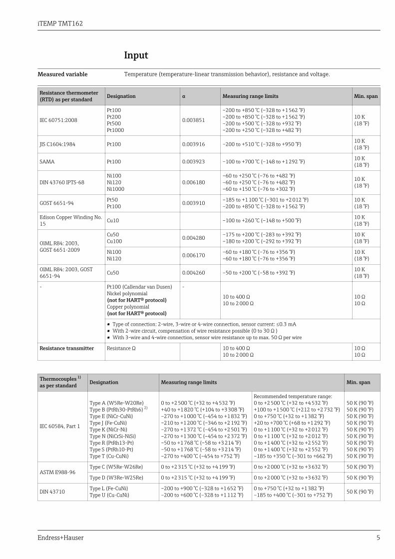
Measured variable Temperature (temperature-linear transmission behavior), resistance and voltage.
Measuring rangeResistance thermometer(RTD) as per standard Designation α Measuring range limits Min. span
IEC 60751:2008
Pt100Pt200Pt500Pt1000
0.003851
–200 to +850 °C (–328 to +1 562 °F)–200 to +850 °C (–328 to +1 562 °F)–200 to +500 °C (–328 to +932 °F)–200 to +250 °C (–328 to +482 °F)
10 K(18 °F)
JIS C1604:1984 Pt100 0.003916 –200 to +510 °C (–328 to +950 °F) 10 K(18 °F)
SAMA Pt100 0.003923 –100 to +700 °C (–148 to +1 292 °F) 10 K(18 °F)
DIN 43760 IPTS-68Ni100Ni120Ni1000
0.006180–60 to +250 °C (–76 to +482 °F)–60 to +250 °C (–76 to +482 °F)–60 to +150 °C (–76 to +302 °F)
10 K(18 °F)
GOST 6651-94 Pt50Pt100 0.003910 –185 to +1 100 °C (–301 to +2 012 °F)
–200 to +850 °C (–328 to +1 562 °F)10 K(18 °F)
Edison Copper Winding No.15 Cu10 –100 to +260 °C (–148 to +500 °F) 10 K
(18 °F)
OIML R84: 2003,GOST 6651-2009
Cu50Cu100 0.004280 –175 to +200 °C (–283 to +392 °F)
–180 to +200 °C (–292 to +392 °F)10 K(18 °F)
Ni100Ni120 0.006170 –60 to +180 °C (–76 to +356 °F)
–60 to +180 °C (–76 to +356 °F)10 K(18 °F)
OIML R84: 2003, GOST6651-94 Cu50 0.004260 –50 to +200 °C (–58 to +392 °F) 10 K
(18 °F)
- Pt100 (Callendar van Dusen)Nickel polynomial(not for HART® protocol)Copper polynomial(not for HART® protocol)
-
10 to 400 Ω10 to 2 000 Ω
10 Ω10 Ω
• Type of connection: 2-wire, 3-wire or 4-wire connection, sensor current: ≤0.3 mA• With 2-wire circuit, compensation of wire resistance possible (0 to 30 Ω )• With 3-wire and 4-wire connection, sensor wire resistance up to max. 50 Ω per wire
Resistance transmitter Resistance Ω 10 to 400 Ω10 to 2 000 Ω
10 Ω10 Ω
Thermocouples 1)
as per standard Designation Measuring range limits Min. span
IEC 60584, Part 1
Type A (W5Re-W20Re)Type B (PtRh30-PtRh6) 2)
Type E (NiCr-CuNi)Type J (Fe-CuNi)Type K (NiCr-Ni)Type N (NiCrSi-NiSi)Type R (PtRh13-Pt)Type S (PtRh10-Pt)Type T (Cu-CuNi)
0 to +2 500 °C (+32 to +4 532 °F)+40 to +1 820 °C (+104 to +3 308 °F)–270 to +1 000 °C (–454 to +1 832 °F)–210 to +1 200 °C (–346 to +2 192 °F)–270 to +1 372 °C (–454 to +2 501 °F)–270 to +1 300 °C (–454 to +2 372 °F)–50 to +1 768 °C (–58 to +3 214 °F)–50 to +1 768 °C (–58 to +3 214 °F)–270 to +400 °C (–454 to +752 °F)
Recommended temperature range:0 to +2 500 °C (+32 to +4 532 °F)+100 to +1 500 °C (+212 to +2 732 °F)0 to +750 °C (+32 to +1 382 °F)+20 to +700 °C (+68 to +1 292 °F)0 to +1 100 °C (+32 to +2 012 °F)0 to +1 100 °C (+32 to +2 012 °F)0 to +1 400 °C (+32 to +2 552 °F)0 to +1 400 °C (+32 to +2 552 °F)–185 to +350 °C (–301 to +662 °F)
50 K (90 °F)50 K (90 °F)50 K (90 °F)50 K (90 °F)50 K (90 °F)50 K (90 °F)50 K (90 °F)50 K (90 °F)50 K (90 °F)
ASTM E988-96Type C (W5Re-W26Re) 0 to +2 315 °C (+32 to +4 199 °F) 0 to +2 000 °C (+32 to +3 632 °F) 50 K (90 °F)
Type D (W3Re-W25Re) 0 to +2 315 °C (+32 to +4 199 °F) 0 to +2 000 °C (+32 to +3 632 °F) 50 K (90 °F)
DIN 43710 Type L (Fe-CuNi)Type U (Cu-CuNi)
–200 to +900 °C (–328 to +1 652 °F)–200 to +600 °C (–328 to +1 112 °F)
0 to +750 °C (+32 to +1 382 °F)–185 to +400 °C (–301 to +752 °F) 50 K (90 °F)
iTEMP TMT162
6 Endress+Hauser
Thermocouples 1)
as per standard Designation Measuring range limits Min. span
• Internal cold junction (Pt100)• External cold junction: configurable value –40 to +85 °C (–40 to +185 °F)• Maximum sensor wire resistance 10 kΩ (if the sensor wire resistance is greater than 10 kΩ, an error message as per NAMUR
NE89 is output) 3)
Voltagetransmitter (mV) Millivolt transmitter (mV) –5 to 30 mV
–20 to 100 mV 5 mV
1) When operating conditions are based on a large temperature range, the transmitter offers you the ability to split the range. For example, a TypeS or R thermocouple can be used for the lower range and a Type B can be used for the upper range. The transmitter is then programmed by theend operator to switch at a predefined temperature. This allows for utilization of the best performance from each individual thermocouple andprovides 1 output that represents the process temperature.
2) High measuring uncertainty for temperatures below 300 °C (572 °F)3) Basic requirements of NE89: Detection of increased wire resistance (e.g. corrosion of contacts or wires) of TC or RTD/4-wire. Warning -
exceeding ambient temperature.
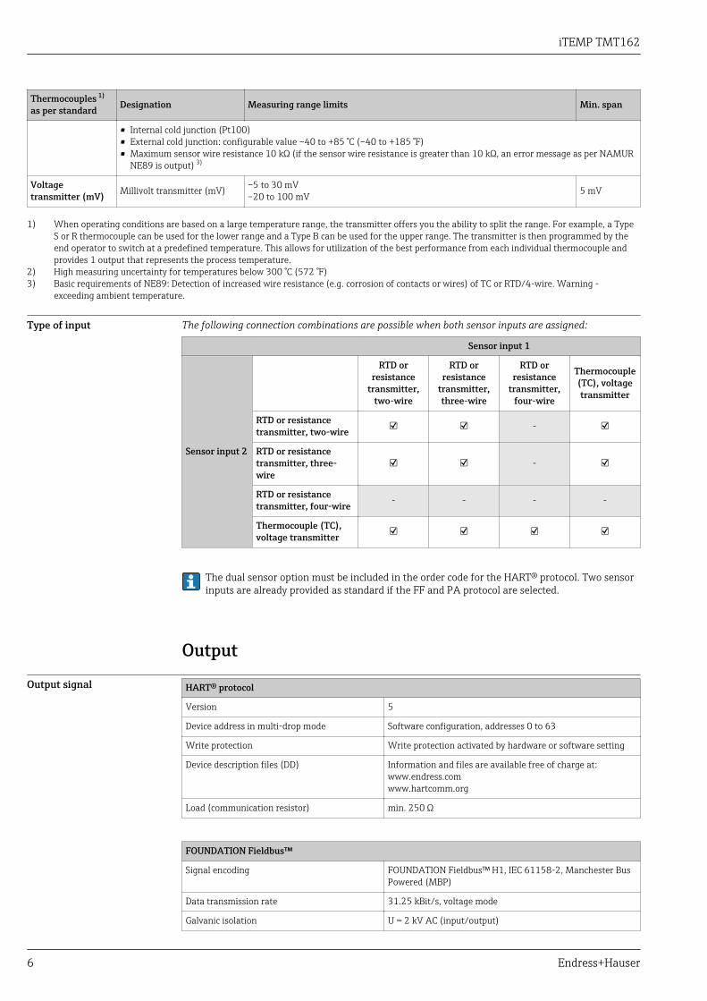
Type of input The following connection combinations are possible when both sensor inputs are assigned:
Sensor input 1
Sensor input 2
RTD orresistance
transmitter,two-wire
RTD orresistance
transmitter,three-wire
RTD orresistance
transmitter,four-wire
Thermocouple(TC), voltagetransmitter
RTD or resistancetransmitter, two-wire -
RTD or resistancetransmitter, three-wire
-
RTD or resistancetransmitter, four-wire - - - -
Thermocouple (TC),voltage transmitter
The dual sensor option must be included in the order code for the HART® protocol. Two sensorinputs are already provided as standard if the FF and PA protocol are selected.
Output
Output signal HART® protocol
Version 5
Device address in multi-drop mode Software configuration, addresses 0 to 63
Write protection Write protection activated by hardware or software setting
Device description files (DD) Information and files are available free of charge at:www.endress.comwww.hartcomm.org
Load (communication resistor) min. 250 Ω
FOUNDATION Fieldbus™
Signal encoding FOUNDATION Fieldbus™ H1, IEC 61158-2, Manchester BusPowered (MBP)
Data transmission rate 31.25 kBit/s, voltage mode
Galvanic isolation U = 2 kV AC (input/output)
iTEMP TMT162
Endress+Hauser 7
PROFIBUS® PA
Signal encoding PROFIBUS® PA in accordance with EN 50170 Volume 2, IEC61158-2, Manchester Bus Powered (MBP)
Data transmission rate 31.25 kBit/s, voltage mode
Galvanic isolation U = 2 kV AC (input/output)
Failure information HART® protocol
Failure information as per NAMUR NE43:Failure information is created if the measuring information is missing or not valid. A complete list of all theerrors occurring in the measuring system is created.
Underranging Linear decrease from 4.0 to 3.8 mA
Overranging Linear increase from 20.0 to 20.5 mA
Failure e.g. sensor breakage; sensorshort-circuit
≤ 3.6 mA ("low") or ≥ 21 mA ("high"), can be selected 1)
1) The "high" alarm can be set between 21.6 mA and 23 mA allowing the flexibility needed to meet therequirements of most control systems.
FOUNDATION Fieldbus™
Status message in accordance with FOUNDATION Fieldbus™ specification
PROFIBUS® PA
Status messages and alarms in accordance with PROFIBUS® PA Profile 3.01/3.02 specification
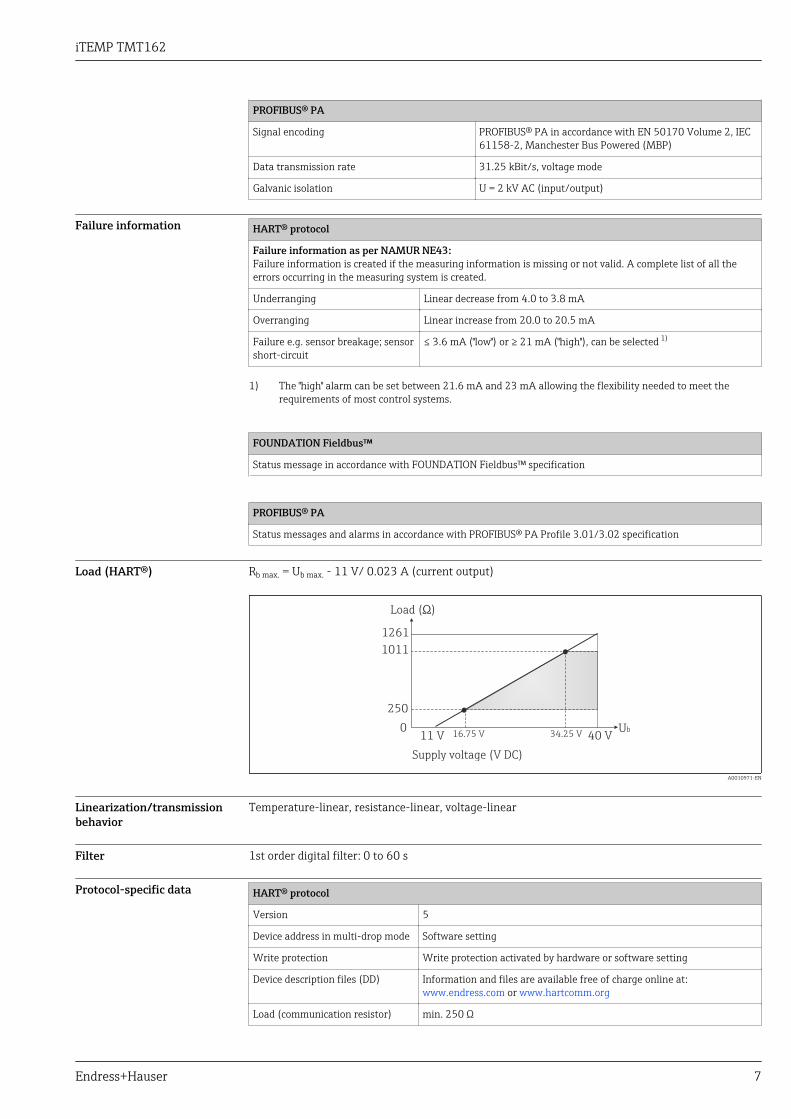
Load (HART®) Rb max. = Ub max. - 11 V/ 0.023 A (current output)
Ub40 V
1261
1011
250
11 V0
34.25 V16.75 V
Supply voltage (V DC)
Load ( )Ω
A0010971-EN
Linearization/transmissionbehavior
Temperature-linear, resistance-linear, voltage-linear
Filter 1st order digital filter: 0 to 60 s
Protocol-specific data HART® protocol
Version 5
Device address in multi-drop mode Software setting
Write protection Write protection activated by hardware or software setting
Device description files (DD) Information and files are available free of charge online at:www.endress.com or www.hartcomm.org
Load (communication resistor) min. 250 Ω
iTEMP TMT162
8 Endress+Hauser
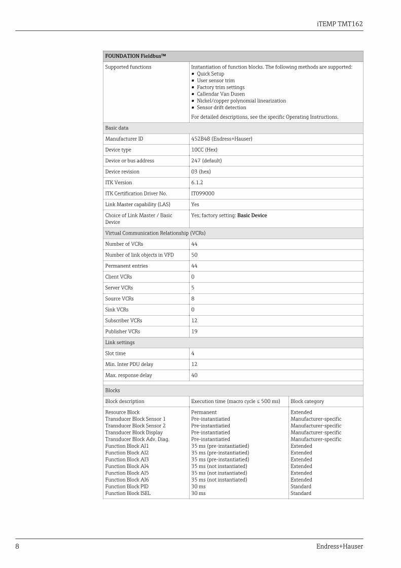
FOUNDATION Fieldbus™
Supported functions Instantiation of function blocks. The following methods are supported:• Quick Setup• User sensor trim• Factory trim settings• Callendar Van Dusen• Nickel/copper polynomial linearization• Sensor drift detection
For detailed descriptions, see the specific Operating Instructions.
Basic data
Manufacturer ID 452B48 (Endress+Hauser)
Device type 10CC (Hex)
Device or bus address 247 (default)
Device revision 03 (hex)
ITK Version 6.1.2
ITK Certification Driver No. IT099000
Link Master capability (LAS) Yes
Choice of Link Master / BasicDevice
Yes; factory setting: Basic Device
Virtual Communication Relationship (VCRs)
Number of VCRs 44
Number of link objects in VFD 50
Permanent entries 44
Client VCRs 0
Server VCRs 5
Source VCRs 8
Sink VCRs 0
Subscriber VCRs 12
Publisher VCRs 19
Link settings
Slot time 4
Min. Inter PDU delay 12
Max. response delay 40
Blocks
Block description Execution time (macro cycle ≤ 500 ms) Block category
Resource BlockTransducer Block Sensor 1Transducer Block Sensor 2Transducer Block DisplayTransducer Block Adv. Diag.Function Block AI1Function Block AI2Function Block AI3Function Block AI4Function Block AI5Function Block AI6Function Block PIDFunction Block ISEL
PermanentPre-instantiatiedPre-instantiatiedPre-instantiatiedPre-instantiatied35 ms (pre-instantiatied)35 ms (pre-instantiatied)35 ms (pre-instantiatied)35 ms (not instantiated)35 ms (not instantiated)35 ms (not instantiated)30 ms30 ms
ExtendedManufacturer-specificManufacturer-specificManufacturer-specificManufacturer-specificExtendedExtendedExtendedExtendedExtendedExtendedStandardStandard

iTEMP TMT162
Endress+Hauser 9
Brief block description
Resource Block The Resource Block contains all the data that clearly identify andcharacterize the device. It is an electronic version of a nameplate on thedevice. In addition to parameters that are needed to operate the device onthe fieldbus, the Resource Block makes information such as the ordercode, device ID, hardware revision, software revision, device release etc.available.
Transducer Block "Sensor 1" and"Sensor 2"
The Transducer Blocks of the field transmitter contain all themeasurement-specific and device-specific parameters which are relevantfor the measurement of the input variables.
Display Transducer The parameters of the "Display" Transducer Block enable the configurationof the display.
Advanced Diagnostic All the parameters for self-monitoring and diagnostics are grouped in thisTransducer Block.
Analog Input (AI) In the AI Function Block, the process variables from the Transducer Blocksare prepared for subsequent automation functions in the control system(e.g. scaling, limit value processing).
PID This function block contains input channel processing, proportionalintegral-differential control (PID) and analog output channel processing.The following can be realized: Basic controls, feedforward control, cascadecontrol and cascade control with limiting.
Input Selector (ISEL) The Input Selector Block enables the selection of up to four inputs andgenerates an output based on the configured action.
PROFIBUS® PA
Profile version 3.02
Manufacturer-specific ID no.: 1549 (hex)
Device or bus address 126 (default)The device address or bus address is configured using either theconfiguration software, e.g. FieldCare, or the DIP switches on theelectronics module. → 17
GSD files Where to obtain GSD files and device drivers:
• GSD file: www.de.endress.com → Downloads → Product code → Mediatype: Software
• Profile of GSD file: www.profibus.com• FieldCare/DTM: https://portal.endress.com/webdownload/
FieldCareDownloadGui• SIMATIC PDM: www.de.endress.com → Downloads → Product code →
Media type: Software
Write protection Write protection activated by hardware setting (DIP switch)
Cyclical data exchange
Output data Value display
Input data Process temperature, internal reference temperature
iTEMP TMT162
10 Endress+Hauser
Brief block description
Physical Block The Physical Block contains all the data that clearly identify anddistinguish the device. It is an electronic version of a nameplate on thedevice. In addition to parameters required to operate the device at thefieldbus, the Physical Block provides information such as order code,device ID, hardware revision, software revision etc. The Physical Block canalso be used to configure the display.
Transducer Block "Sensor 1" and"Sensor 2"
The Transducer Blocks of the field transmitter contain all themeasurement-specific and device-specific parameters which are relevantfor the measurement of the input variables.
Analog Input (AI) In the AI Function Block, the process variables from the Transducer Blocksare prepared for subsequent automation functions in the control system(e.g. scaling, limit value processing).
Switch-on delay HART® protocol
4 s, during switch-on procedure Ia ≤ 4.0 mA
FOUNDATION Fieldbus™
8 s
PROFIBUS® PA
8 s
Power supply
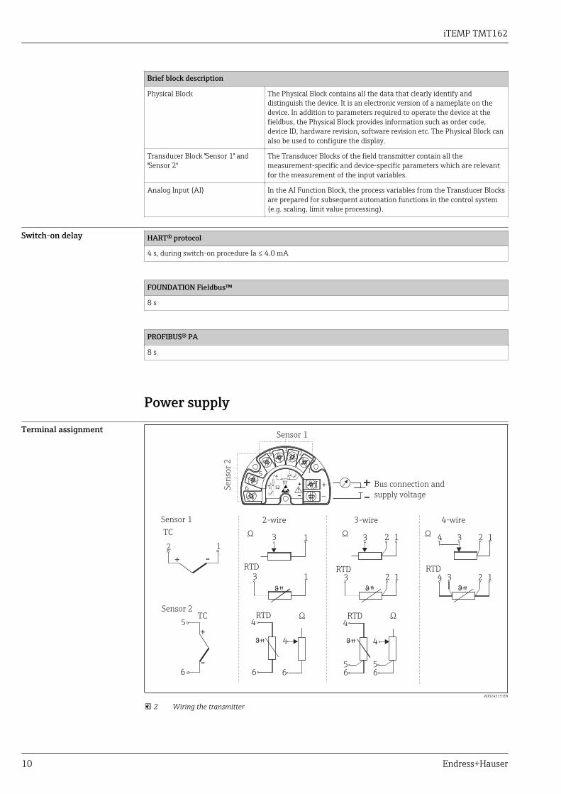
Terminal assignment
4
333
33 3
111
111 1
4
4
22
22 2
RTDRTDRTD
Ω
5
5
56 666
RTDRTD
6
4
4
4
4
TC
TC
+
-
1
23
5
6
+ -34
S13
S2
-
+
+
-!
Ω Ω
ΩΩ
4-wire2-wire 3-wire
Bus connection and
supply voltage
Sensor 1
Se
nso
r 2
Sensor 1
Sensor 2
A0024515-EN
2 Wiring the transmitter

iTEMP TMT162
Endress+Hauser 11
Supply voltage HART® protocol
Ub= 11 to 40 V (8 to 40 V without display), reverse polarity protection
The transmitter must be powered by an 11 to 40 VDC power supply in accordance with NECClass 02 (low voltage/low current) with restricted power limited to 8 A/150 VA in the event ofa short-circuit (in accordance with IEC 61010-1, CSA 1010.1-92).
FOUNDATION Fieldbus™
Ub= 9 to 32 V, polarity-independent (reverse polarity protection for T17 housing), maximum voltage Ub = 35 V.According to IEC 60079-27, FISCO/FNICO
PROFIBUS® PA
Ub= 9 to 32 V, polarity-independent (reverse polarity protection for T17 housing), maximum voltage Ub = 35 V.According to IEC 60079-27, FISCO/FNICO
Current consumption HART® protocol
Current consumptionMinimum current consumptionCurrent limit
3.6 to 23 mA≤ 3.5 mA≤ 23 mA
FOUNDATION Fieldbus™
Current consumption (device basic current)Switch-on current (device inrush current)Error current FDE (Fault Disconnection Electronic)
≤ 11 mA≤ 11 mA0 mA
PROFIBUS® PA
Current consumption (device basic current)Error current FDE (Fault Disconnection Electronic)
≤ 11 mA0 mA
Terminals 2.5 mm2 (12 AWG) plus ferrule
Cable entries Version Type
Thread 2x thread ½" NPT
2x thread M20
2x thread G½"
Cable gland 2x coupling M20
Device connector Version Type
Thread and fieldbusconnector
2x thread ½" NPT1x connector 7/8" FF
2x thread M20x1.51x connector 7/8" FF
Residual ripple (HART®) Perm. residual ripple USS ≤ 3 V at Ub ≥ 13.5 V, fmax. = 1 kHz
Performance characteristics
Response time Measured value update < 1 s per channel, depending on the type of sensor and connection method
iTEMP TMT162
12 Endress+Hauser
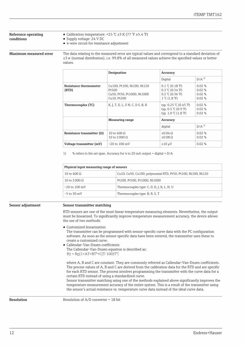
Reference operatingconditions
• Calibration temperature: +25 °C ±3 K (77 °F ±5.4 °F)• Supply voltage: 24 V DC• 4-wire circuit for resistance adjustment
Maximum measured error The data relating to the measured error are typical values and correspond to a standard deviation of±3 s (normal distribution), i.e. 99.8% of all measured values achieve the specified values or bettervalues.
Designation Accuracy
Digital D/A 1)
Resistance thermometer(RTD)
Cu100, Pt100, Ni100, Ni120Pt500Cu50, Pt50, Pt1000, Ni1000Cu10, Pt200
0.1 °C (0.18 °F)0.3 °C (0.54 °F)0.2 °C (0.36 °F)1 °C (1.8 °F)
0.02 %0.02 %0.02 %0.02 %
Thermocouples (TC) K, J, T, E, L, U N, C, D S, B, R typ. 0.25 °C (0.45 °F)typ. 0.5 °C (0.9 °F)typ. 1.0 °C (1.8 °F)
0.02 %0.02 %0.02 %
Measuring range Accuracy
digital D/A 1)
Resistance transmitter (Ω) 10 to 400 Ω10 to 2 000 Ω
±0.04 Ω±0.08 Ω
0.02 %0.02 %
Voltage transmitter (mV) –20 to 100 mV ±10 µV 0.02 %
1) % refers to the set span. Accuracy for 4 to 20 mA output = digital + D/A
Physical input measuring range of sensors
10 to 400 Ω Cu10, Cu50, Cu100, polynomial RTD, Pt50, Pt100, Ni100, Ni120
10 to 2 000 Ω Pt200, Pt500, Pt1000, Ni1000
–20 to 100 mV Thermocouples type: C, D, E, J, K, L, N, U
–5 to 30 mV Thermocouples type: B, R, S, T
Sensor adjustment Sensor transmitter matching
RTD sensors are one of the most linear temperature measuring elements. Nevertheless, the outputmust be linearized. To significantly improve temperature measurement accuracy, the device allowsthe use of two methods:
• Customized linearizationThe transmitter can be programmed with sensor-specific curve data with the PC configurationsoftware. As soon as the sensor-specific data have been entered, the transmitter uses these tocreate a customized curve.
• Callendar-Van-Dusen coefficientsThe Callendar-Van-Dusen equation is described as:RT = R0[1+AT+BT²+C(T-100)T³] where A, B and C are constant. They are commonly referred as Callendar-Van-Dusen coefficients.The precise values of A, B and C are derived from the calibration data for the RTD and are specificfor each RTD sensor. The process involves programming the transmitter with the curve data for acertain RTD instead of using a standardized curve.Sensor transmitter matching using one of the methods explained above significantly improves thetemperature measurement accuracy of the entire system. This is a result of the transmitter usingthe sensor’s actual resistance vs. temperature curve data instead of the ideal curve data.
Resolution Resolution of A/D converter = 18 bit
iTEMP TMT162
Endress+Hauser 13
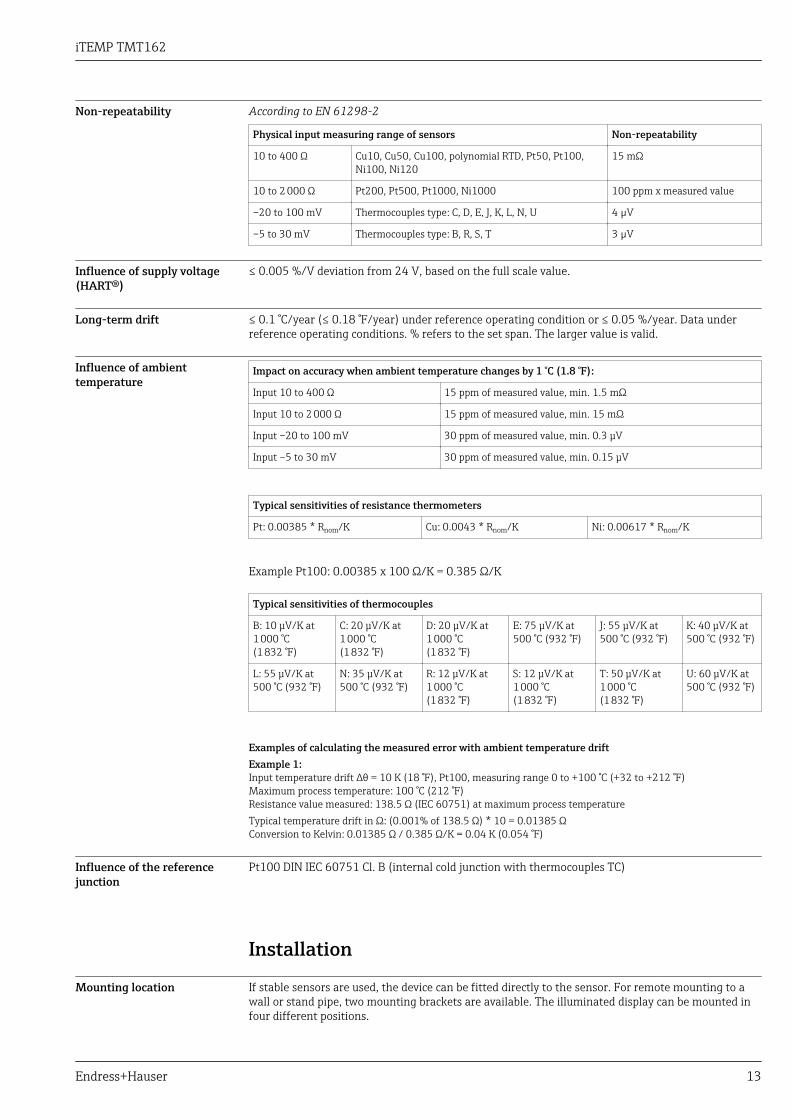
Non-repeatability According to EN 61298-2
Physical input measuring range of sensors Non-repeatability
10 to 400 Ω Cu10, Cu50, Cu100, polynomial RTD, Pt50, Pt100,Ni100, Ni120
15 mΩ
10 to 2 000 Ω Pt200, Pt500, Pt1000, Ni1000 100 ppm x measured value
–20 to 100 mV Thermocouples type: C, D, E, J, K, L, N, U 4 µV
–5 to 30 mV Thermocouples type: B, R, S, T 3 µV
Influence of supply voltage(HART®)
≤ 0.005 %/V deviation from 24 V, based on the full scale value.
Long-term drift ≤ 0.1 °C/year (≤ 0.18 °F/year) under reference operating condition or ≤ 0.05 %/year. Data underreference operating conditions. % refers to the set span. The larger value is valid.
Influence of ambienttemperature
Impact on accuracy when ambient temperature changes by 1 °C (1.8 °F):
Input 10 to 400 Ω 15 ppm of measured value, min. 1.5 mΩ
Input 10 to 2 000 Ω 15 ppm of measured value, min. 15 mΩ
Input –20 to 100 mV 30 ppm of measured value, min. 0.3 μV
Input –5 to 30 mV 30 ppm of measured value, min. 0.15 μV
Typical sensitivities of resistance thermometers
Pt: 0.00385 * Rnom/K Cu: 0.0043 * Rnom/K Ni: 0.00617 * Rnom/K
Example Pt100: 0.00385 x 100 Ω/K = 0.385 Ω/K
Typical sensitivities of thermocouples
B: 10 μV/K at1 000 °C(1 832 °F)
C: 20 μV/K at1 000 °C(1 832 °F)
D: 20 μV/K at1 000 °C(1 832 °F)
E: 75 μV/K at500 °C (932 °F)
J: 55 μV/K at500 °C (932 °F)
K: 40 μV/K at500 °C (932 °F)
L: 55 μV/K at500 °C (932 °F)
N: 35 μV/K at500 °C (932 °F)
R: 12 μV/K at1 000 °C(1 832 °F)
S: 12 μV/K at1 000 °C(1 832 °F)
T: 50 μV/K at1 000 °C(1 832 °F)
U: 60 μV/K at500 °C (932 °F)
Examples of calculating the measured error with ambient temperature driftExample 1:Input temperature drift Δθ = 10 K (18 °F), Pt100, measuring range 0 to +100 °C (+32 to +212 °F)Maximum process temperature: 100 °C (212 °F)Resistance value measured: 138.5 Ω (IEC 60751) at maximum process temperatureTypical temperature drift in Ω: (0.001% of 138.5 Ω) * 10 = 0.01385 ΩConversion to Kelvin: 0.01385 Ω / 0.385 Ω/K = 0.04 K (0.054 °F)
Influence of the referencejunction
Pt100 DIN IEC 60751 Cl. B (internal cold junction with thermocouples TC)
Installation
Mounting location If stable sensors are used, the device can be fitted directly to the sensor. For remote mounting to awall or stand pipe, two mounting brackets are available. The illuminated display can be mounted infour different positions.
iTEMP TMT162
14 Endress+Hauser
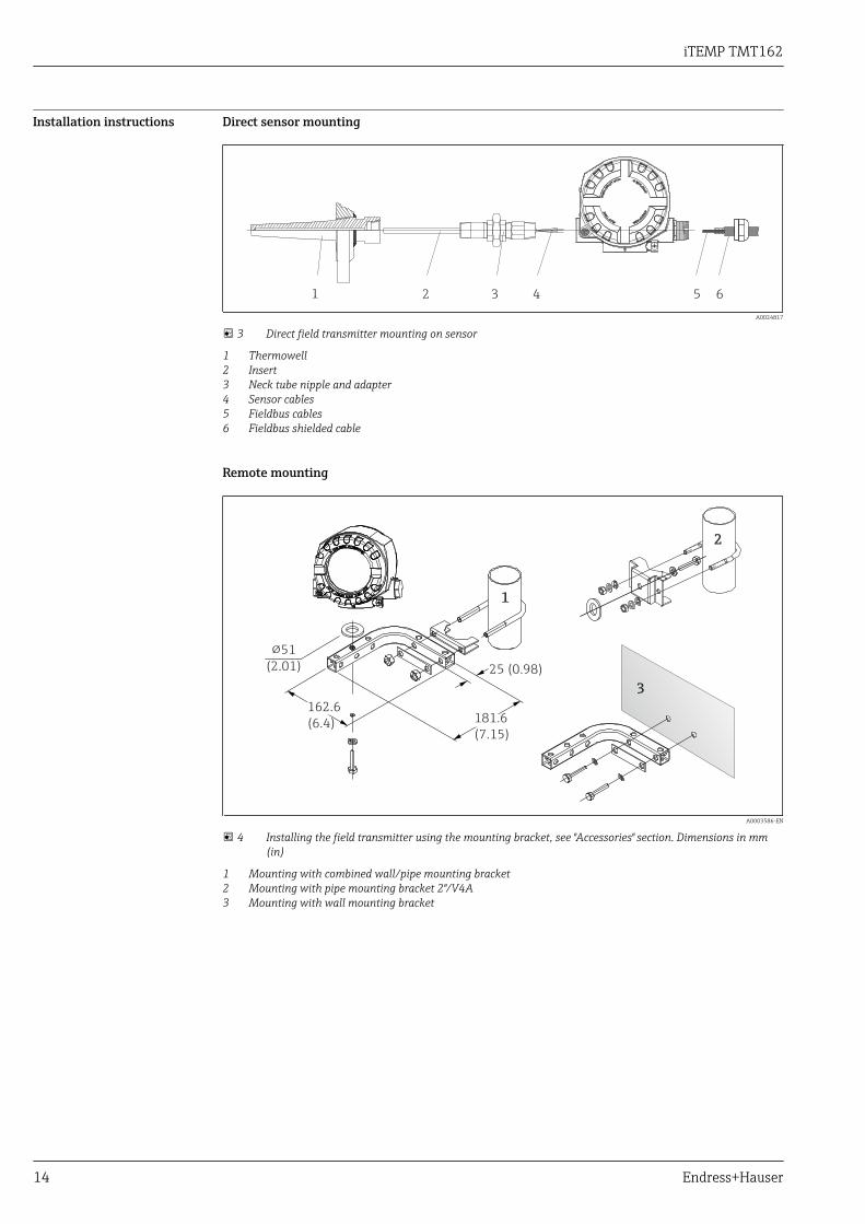
Installation instructions Direct sensor mounting
1 2 3 4 5 6
KEEP
T
IGH
T
WH
EN
CIR
CU
ITALIVE IN
EXP
LO
SIV
EATM
O
S
PH
ERE
aaaaaabbbbbb
A0024817
3 Direct field transmitter mounting on sensor
1 Thermowell2 Insert3 Neck tube nipple and adapter4 Sensor cables5 Fieldbus cables6 Fieldbus shielded cable
Remote mounting
1
3
2
25 (0.98)
181.6
(7.15)
162.6
(6.4)
!51
(2.01)
A0003586-EN
4 Installing the field transmitter using the mounting bracket, see "Accessories" section. Dimensions in mm(in)
1 Mounting with combined wall/pipe mounting bracket2 Mounting with pipe mounting bracket 2"/V4A3 Mounting with wall mounting bracket
iTEMP TMT162
Endress+Hauser 15
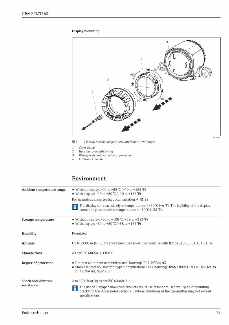
Display mounting
1
2
3
4
90°
90°90°
90°
A0025417
5 4 display installation positions, attachable in 90° stages
1 Cover clamp2 Housing cover with O-ring3 Display with retainer and twist protection4 Electronics module
Environment
Ambient temperature range • Without display: –40 to +85 °C (–40 to +185 °F)• With display: –40 to +80 °C (–40 to +176 °F)For hazardous areas see Ex documentation → 22
The display can react slowly at temperatures < –20 °C (–4 °F). The legibility of the displaycannot be guaranteed at temperatures < –30 °C (–22 °F).
Storage temperature • Without display: –50 to +100 °C (–58 to +212 °F)• With display: –50 to +80 °C (–58 to +176 °F)
Humidity Permitted
Altitude Up to 2 000 m (6 560 ft) above mean sea level in accordance with IEC 61010-1, CSA 1010.1-92
Climate class As per IEC 60654-1, Class C
Degree of protection • Die-cast aluminum or stainless steel housing: IP67, NEMA 4X• Stainless steel housing for hygienic applications (T17 housing): IP66 / IP68 (1.83 m H2O for 24
h), NEMA 4X, NEMA 6P
Shock and vibrationresistance
2 to 150 Hz at 3g as per IEC 60068-2-6
The use of L-shaped mounting brackets can cause resonance (see wall/pipe 2" mountingbracket in the 'Accessories' section). Caution: vibrations at the transmitter may not exceedspecifications.
iTEMP TMT162
16 Endress+Hauser
Electromagneticcompatibility (EMC)
CE compliance
The device meets all the requirements specified in IEC 61326, Amendment 1, 1998 and NAMURNE21. This recommendation is a uniform and practical way of determining whether the devices usedin laboratories and process control are immune to interference with the objective of increasing theirfunctional safety.
ESD (electrostatic discharge) EN/IEC 61000-4-2 6 kV cont., 8 kV air
Electromagnetic fields EN/IEC 61000-4-3 0.08 to 4 GHz 10 V/m
Burst (fast transients) EN/IEC 61000-4-4 1 kV
Surge (surge voltage) EN/IEC 61000-4-5 1 kV assym.
Conducted RF EN/IEC 61000-4-6 0.01 to 80 MHz 10 V
Measuring category Measuring category II as per IEC 61010-1. The measuring category is provided for measuring onpower circuits that are directly connected electrically with the low-voltage network.
Degree of contamination Pollution degree 2 as per IEC 61010-1.
Mechanical construction
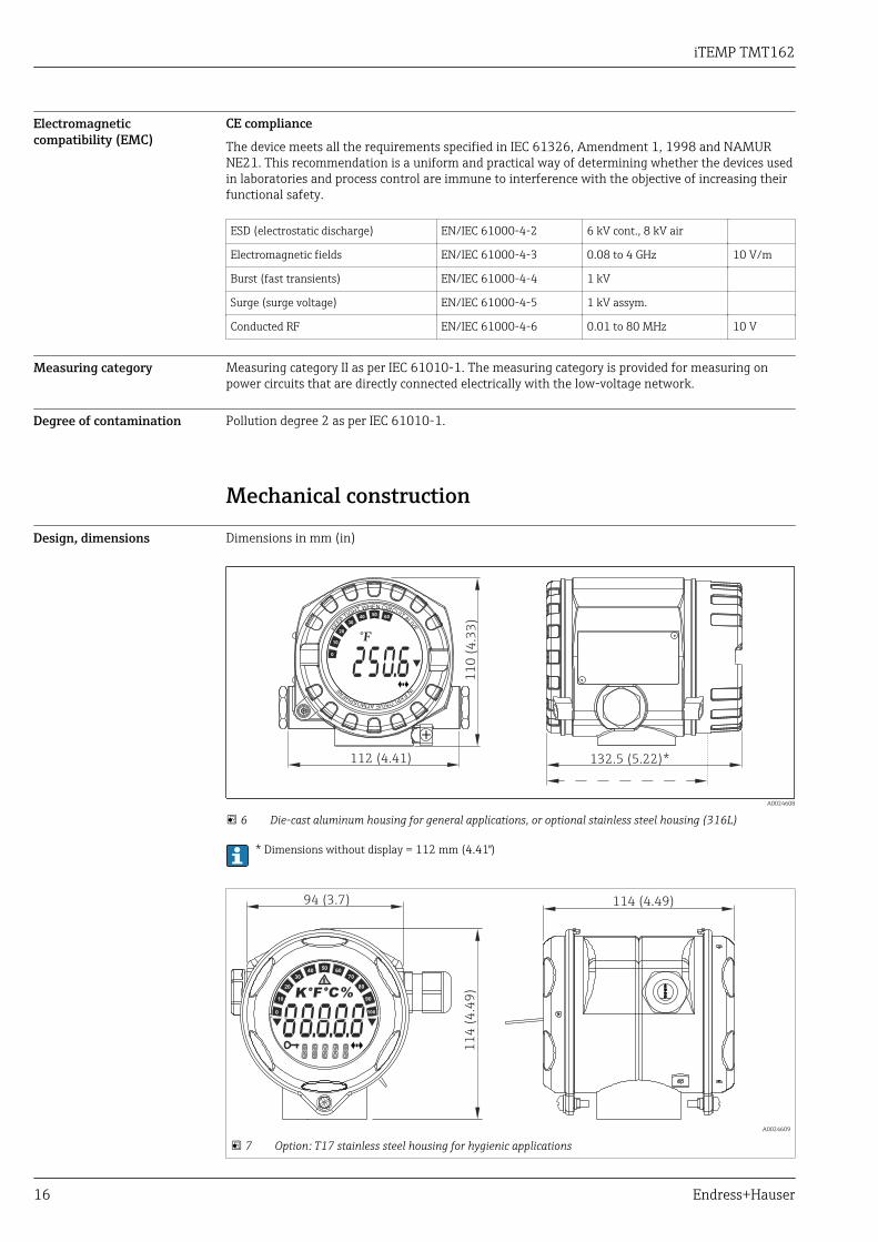
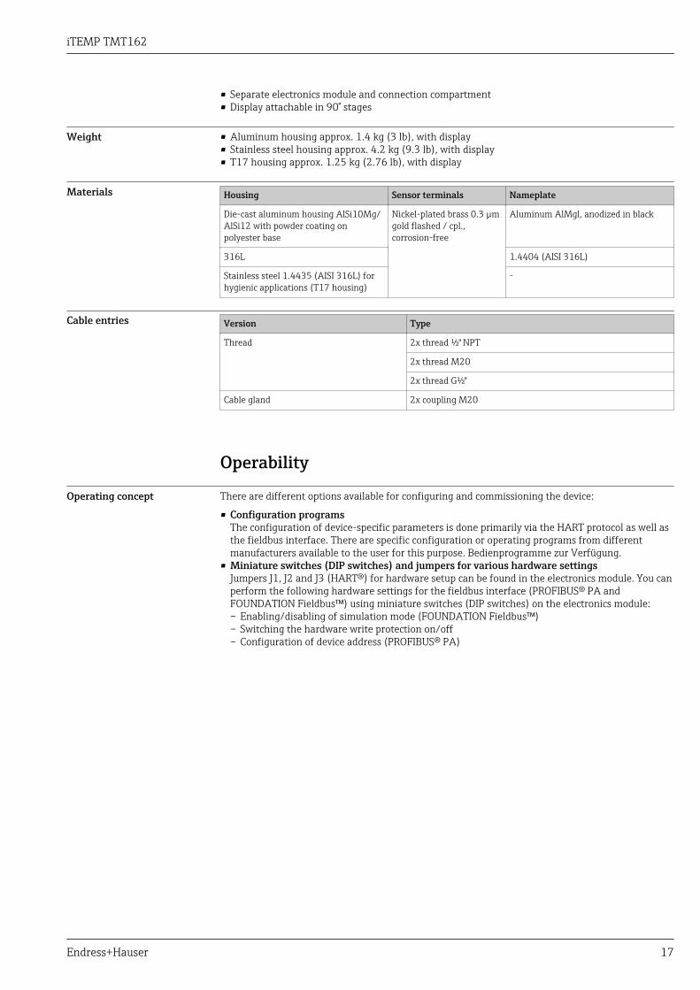
Design, dimensions Dimensions in mm (in)
KEE
PTIG
HT WHEN CIRCUITAL
IVE
IN
EXPLOSIVEATMOSPH
ER
E
°F10
0
20
30
4050
60
70
80
90
100
11
0(4
.33
)
112 (4.41) 132.5 (5.22)*
A0024608
6 Die-cast aluminum housing for general applications, or optional stainless steel housing (316L)
* Dimensions without display = 112 mm (4.41")
°C°F %K10
0
20
30
4050
60
70
80
90
100
!
11
4 (
4.4
9)
114 (4.49)94 (3.7)
A0024609
7 Option: T17 stainless steel housing for hygienic applications
iTEMP TMT162
Endress+Hauser 17
• Separate electronics module and connection compartment• Display attachable in 90° stages
Weight • Aluminum housing approx. 1.4 kg (3 lb), with display• Stainless steel housing approx. 4.2 kg (9.3 lb), with display• T17 housing approx. 1.25 kg (2.76 lb), with display
Materials Housing Sensor terminals Nameplate
Die-cast aluminum housing AlSi10Mg/AlSi12 with powder coating onpolyester base
Nickel-plated brass 0.3 µmgold flashed / cpl.,corrosion-free
Aluminum AlMgl, anodized in black
316L 1.4404 (AISI 316L)
Stainless steel 1.4435 (AISI 316L) forhygienic applications (T17 housing)
-
Cable entries Version Type
Thread 2x thread ½" NPT
2x thread M20
2x thread G½"
Cable gland 2x coupling M20
Operability
Operating concept There are different options available for configuring and commissioning the device:
• Configuration programsThe configuration of device-specific parameters is done primarily via the HART protocol as well asthe fieldbus interface. There are specific configuration or operating programs from differentmanufacturers available to the user for this purpose. Bedienprogramme zur Verfügung.
• Miniature switches (DIP switches) and jumpers for various hardware settingsJumpers J1, J2 and J3 (HART®) for hardware setup can be found in the electronics module. You canperform the following hardware settings for the fieldbus interface (PROFIBUS® PA andFOUNDATION Fieldbus™) using miniature switches (DIP switches) on the electronics module:– Enabling/disabling of simulation mode (FOUNDATION Fieldbus™)– Switching the hardware write protection on/off– Configuration of device address (PROFIBUS® PA)
iTEMP TMT162
18 Endress+Hauser
°C °C
PROFIBUSADDRESS
SIM(FF)
WRITELOCK
ON
OFF
Software6432168421
1
2
A0024548
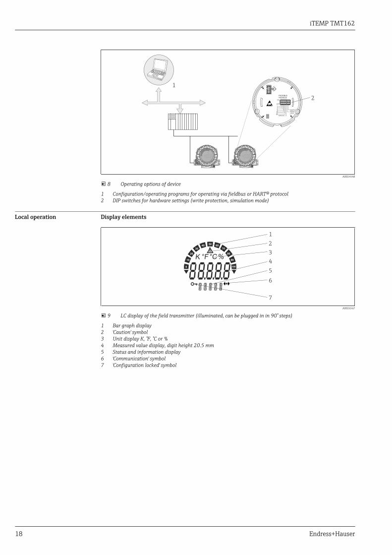
8 Operating options of device
1 Configuration/operating programs for operating via fieldbus or HART® protocol2 DIP switches for hardware settings (write protection, simulation mode)
Local operation Display elements
°C°F %K10
0
20
30
4050
60
70
80
90
100
!
1
2
3
4
5
6
7
A0024547
9 LC display of the field transmitter (illuminated, can be plugged in in 90° steps)
1 Bar graph display2 'Caution' symbol3 Unit display K, °F, °C or %4 Measured value display, digit height 20.5 mm5 Status and information display6 'Communication' symbol7 'Configuration locked' symbol
iTEMP TMT162
Endress+Hauser 19
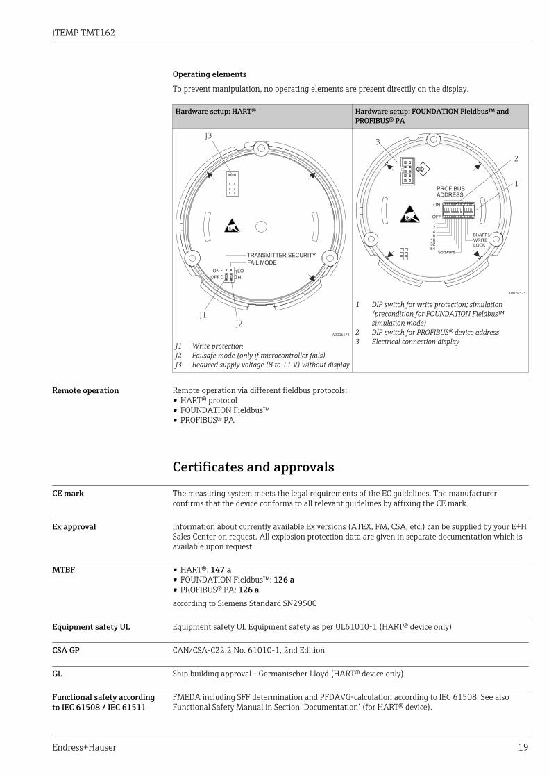
Operating elements
To prevent manipulation, no operating elements are present directily on the display.
Hardware setup: HART® Hardware setup: FOUNDATION Fieldbus™ andPROFIBUS® PA
FAIL MODE
HI
TRANSMITTER SECURITY
J3
J2J1
LO
OFF
ON
A0026573
J1 Write protectionJ2 Failsafe mode (only if microcontroller fails)J3 Reduced supply voltage (8 to 11 V) without display
PROFIBUSADDRESS
SIM(FF)
WRITELOCK
ON
OFF
2
1
Software6432168421
3
A0026575
1 DIP switch for write protection; simulation(precondition for FOUNDATION Fieldbus™simulation mode)
2 DIP switch for PROFIBUS® device address3 Electrical connection display
Remote operation Remote operation via different fieldbus protocols:• HART® protocol• FOUNDATION Fieldbus™• PROFIBUS® PA
Certificates and approvals
CE mark The measuring system meets the legal requirements of the EC guidelines. The manufacturerconfirms that the device conforms to all relevant guidelines by affixing the CE mark.
Ex approval Information about currently available Ex versions (ATEX, FM, CSA, etc.) can be supplied by your E+HSales Center on request. All explosion protection data are given in separate documentation which isavailable upon request.
MTBF • HART®: 147 a• FOUNDATION Fieldbus™: 126 a• PROFIBUS® PA: 126 aaccording to Siemens Standard SN29500
Equipment safety UL Equipment safety UL Equipment safety as per UL61010-1 (HART® device only)
CSA GP CAN/CSA-C22.2 No. 61010-1, 2nd Edition
GL Ship building approval - Germanischer Lloyd (HART® device only)
Functional safety accordingto IEC 61508 / IEC 61511
FMEDA including SFF determination and PFDAVG-calculation according to IEC 61508. See alsoFunctional Safety Manual in Section ’Documentation’ (for HART® device).
iTEMP TMT162
20 Endress+Hauser
FOUNDATION Fieldbuscertification
The temperature transmitter is certified and registered by the Fieldbus FOUNDATION. Themeasuring system meets all the requirements of the following specifications:• Certified in accordance with FOUNDATION Fieldbus™ specification• FOUNDATION Fieldbus™ H1• Interoperability Test Kit (ITK), revision status 6.1.2, device certification number → 7: The
device can also be operated with certified devices of other manufacturers.• Physical Layer Conformance Test of the Fieldbus FOUNDATION™ (FF-830 FS 1.0)
PROFIBUS® PA certification The temperature transmitter is certified and registered by the PNO (PROFIBUS® Nutzerorganisatione. V.), PROFIBUS user organization. The device meets all the requirements of the followingspecifications:• Certified in accordance with PROFIBUS® PA Profile 3.02.• The device can also be operated with certified devices of other manufacturers (interoperability).
Other standards andguidelines
• IEC 60529: Degrees of protection provided by enclosures (IP code)• IEC 61010: Safety requirements for electrical equipment for measurement, control and laboratory
use.• IEC 61326: Electromagnetic compatibility (EMC requirements)• NAMUR - Standardization organization for measurement and control processes in the chemical
and pharmaceutical industry. (www.namur.de)• NEMA - Standardization organization for the electrical industry.
Ordering informationDetailed ordering information is available from the following sources:• In the Product Configurator on the Endress+Hauser website: www.endress.com → Select your
country → Products → Select measuring technology, software or components → Select the product(picklists: measurement method, product family etc.) → Device support (right-hand column):Configure the selected product → The Product Configurator for the selected product opens.
• From your Endress+Hauser Sales Center: www.addresses.endress.comProduct Configurator - the tool for individual product configuration• Up-to-the-minute configuration data• Depending on the device: Direct input of measuring point-specific information such as
measuring range or operating language• Automatic verification of exclusion criteria• Automatic creation of the order code and its breakdown in PDF or Excel output format• Ability to order directly in the Endress+Hauser Online Shop
AccessoriesVarious accessories, which can be ordered with the device or subsequently from Endress+Hauser, areavailable for the device. Detailed information on the order code in question is available from yourlocal Endress+Hauser sales center or on the product page of the Endress+Hauser website:www.endress.com.
Always quote the serial number of the device when ordering accessories!
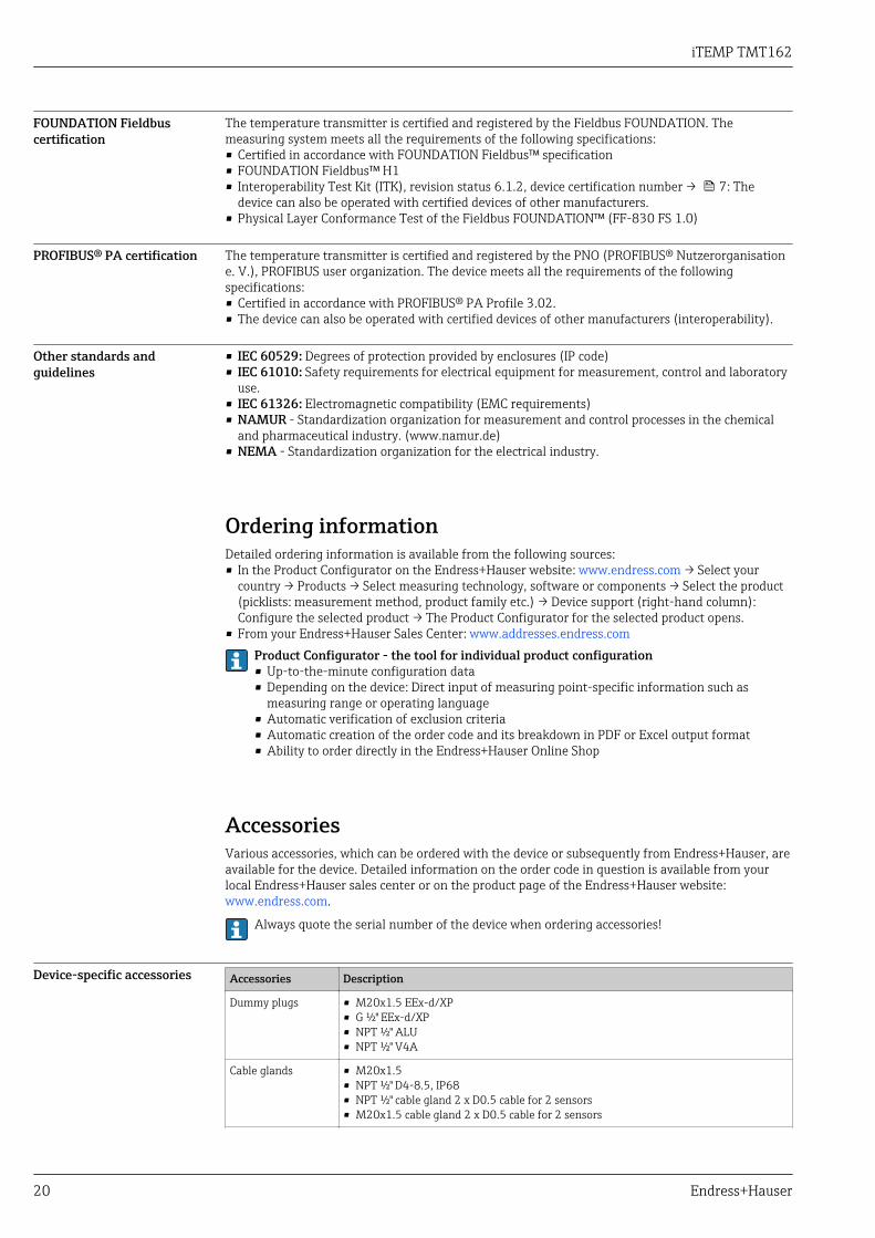
Device-specific accessories Accessories Description
Dummy plugs • M20x1.5 EEx-d/XP• G ½" EEx-d/XP• NPT ½" ALU• NPT ½" V4A
Cable glands • M20x1.5• NPT ½" D4-8.5, IP68• NPT ½" cable gland 2 x D0.5 cable for 2 sensors• M20x1.5 cable gland 2 x D0.5 cable for 2 sensors
iTEMP TMT162
Endress+Hauser 21
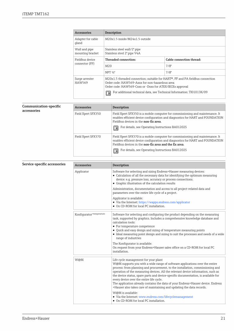
Accessories Description
Adapter for cablegland
M20x1.5 inside/M24x1.5 outside
Wall and pipemounting bracket
Stainless steel wall/2" pipeStainless steel 2" pipe V4A
Fieldbus deviceconnector (FF)
Threaded connection: Cable connection thread:
M20 7/8"
NPT ½" 7/8"
Surge arresterHAW569
M20x1.5 threaded connection; suitable for HART®, FF and PA fieldbus connectionOrder code: HAW569-Axxx for non-hazardous areaOrder code: HAW569-Cxxx or -Dxxx for ATEX/IECEx approval
For additional technical data, see Technical Information: TI01013K/09
Communication-specificaccessories
Accessories Description
Field Xpert SFX350 Field Xpert SFX350 is a mobile computer for commissioning and maintenance. Itenables efficient device configuration and diagnostics for HART and FOUNDATIONFieldbus devices in the non-Ex area.
For details, see Operating Instructions BA01202S
Field Xpert SFX370 Field Xpert SFX370 is a mobile computer for commissioning and maintenance. Itenables efficient device configuration and diagnostics for HART and FOUNDATIONFieldbus devices in the non-Ex area and the Ex area.
For details, see Operating Instructions BA01202S
Service-specific accessories Accessories Description
Applicator Software for selecting and sizing Endress+Hauser measuring devices:• Calculation of all the necessary data for identifying the optimum measuring
device: e.g. pressure loss, accuracy or process connections.• Graphic illustration of the calculation results
Administration, documentation and access to all project-related data andparameters over the entire life cycle of a project.
Applicator is available:• Via the Internet: https://wapps.endress.com/applicator• On CD-ROM for local PC installation.
Konfigurator+temperature Software for selecting and configuring the product depending on the measuringtask, supported by graphics. Includes a comprehensive knowledge database andcalculation tools:• For temperature competence• Quick and easy design and sizing of temperature measuring points• Ideal measuring point design and sizing to suit the processes and needs of a wide
range of industries
The Konfigurator is available:On request from your Endress+Hauser sales office on a CD-ROM for local PCinstallation.
W@M Life cycle management for your plantW@M supports you with a wide range of software applications over the entireprocess: from planning and procurement, to the installation, commissioning andoperation of the measuring devices. All the relevant device information, such asthe device status, spare parts and device-specific documentation, is available forevery device over the entire life cycle.The application already contains the data of your Endress+Hauser device. Endress+Hauser also takes care of maintaining and updating the data records.
W@M is available:• Via the Internet: www.endress.com/lifecyclemanagement• On CD-ROM for local PC installation.
iTEMP TMT162
22 Endress+Hauser
FieldCare FDT-based plant asset management tool from Endress+Hauser.It can configure all smart field units in your system and helps you manage them. Byusing the status information, it is also a simple but effective way of checking theirstatus and condition.
For details, see Operating Instructions BA00027S and BA00059S
System components Accessories Description
Graphic Data ManagerMemograph M
The Memograph M graphic data manager provides information on all the relevantprocess variables. Measured values are recorded correctly, limit values aremonitored and measuring points analyzed. The data are stored in the 256 MBinternal memory and also on a SD card or USB stick.
For details, see Technical Information TI133R/09
Paperless recorderEcograph T
Multi-channel data recording system with LC color graphic display (120 mm / 4.7"screen size), galvanically isolated universal inputs (U, I, TC, RTD), digital input,transmitter power supply, limit relay, communication interfaces (USB, Ethernet,RS232/485), Internal flash memory and compact flash card.
For details, see Technical Information TI01079R/09
RID14, RID16 8-channel field display unit with FOUNDATION Fieldbus™ or PROFIBUS® PAprotocol - for easy integration into existing fieldbus systems. RID14 as version inflameproof housing.
For details, see Technical Information TI00145R/09 (RID14) andTI00146R/09 (RID16)
Documentation• FOUNDATION Fieldbus™ Function Blocks manual (BA062S/04)• Supplementary ATEX documentation:
– ATEX/IECEx II 2G Ex d IIC T6...T4 Gb: XA00031R/09/a3– ATEX/IECEx II 2D Ex tb IIIC T110 °C Db: XA00032R/09/a3– ATEX/IECEx II 1G Ex ia IIC T6/T5/T4: XA00033R/09/a3– ATEX II 3G Ex nA IIC T6…T4 Gc: XA00035R/09/a3– ATEX/IEC Installation type Ex ia + Ex d: XA01025R/09/a3– ATEX II 3G Ex ic IIC T6…T4 Gc: XA00062R/09/a3
• iTEMP TMT162 HART® Operating Instructions (BA00132R/09/) + Functional Safety Manual(SD005R/09/en)iTEMP TMT162 HART® - Brief Operating Instructions (KA00250R/09)
• iTEMP TMT162 FOUNDATION Fieldbus™ - Operating Instructions (BA00224R/09/en)iTEMP TMT162 FOUNDATION Fieldbus™ - Brief Operating Instructions (KA00189R/09)
• iTEMP TMT162 PROFIBUS® PA - Operating Instructions (BA00275R/09/en)iTEMP TMT162 PROFIBUS® PA - Brief Operating Instructions (KA00276R/09)
Technical Information Omnigrad S TMT162R and TMT162C (TI00266T/02/en andTI00267T/02/en)


www.addresses.endress.com