Introduction - Farnell element142. Double click the GDB OpenOCD Debugging configuration from window....
94
Introduction The EVAL-ADICUP360 is an Arduino-like platform based on the ADUCM360 fully integrated, 3.9 kSPS, 24-bit data acquisition system that incorporates dual high performance, multichannel sigma-delta (Σ-Δ) analog-to-digital converters (ADCs), a 32-bit ARM Cortex™-M3 processor, and Flash/EE memory on a single chip. The platform has an Arduino-Due form factor and has two additional PMOD connectors. An Eclipse based development environment is provided for code development and debugging. The base platform is accompanied by a set of shields provided by Analog Devices but it can also work with 3rd party Aduino shields. This guide is structured as follows: Hardware - Contains hardware-related information about the base board and the various shields ● Quick Start Guides - Provides all the necessary steps to get the software environment up and ● running Reference Designs - Contains detailed descriptions of the software reference designs available for ● the base board and the shields Help and Support - Provides info on where to get support on any questions you might have ● regarding the hardware or the software Tool Chain Guides This chapter provides all the necessary steps to get the software environment up and running. It contains two main sections: Tool Chain Download & Installation Guide - Provides all the necessary instructions on how to ● download and install the customized software development environment for ADuCM360 based on Eclipse IDE. Tool Chain Setup & User Guide - Provides information about using the customized Eclipse IDE, in ● particular, the process of importing, building, debugging, and creating user applications for the ADuCM360 microcontroller. Using EVAL-ADICUP360 with IAR and Keil IDEs - Provides detailed information how to use the ● EVAL-ADICUP360 board with other IDEs than Eclipse, such as IAR Embedded Workbench and Keil µVision.
Transcript of Introduction - Farnell element142. Double click the GDB OpenOCD Debugging configuration from window....

Introduction
The EVAL-ADICUP360 is an Arduino-like platform based on the ADUCM360 fully integrated, 3.9kSPS, 24-bit data acquisition system that incorporates dual high performance, multichannelsigma-delta (Σ-Δ) analog-to-digital converters (ADCs), a 32-bit ARM Cortex™-M3 processor, andFlash/EE memory on a single chip. The platform has an Arduino-Due form factor and has twoadditional PMOD connectors. An Eclipse based development environment is provided for codedevelopment and debugging. The base platform is accompanied by a set of shields provided byAnalog Devices but it can also work with 3rd party Aduino shields.
This guide is structured as follows:
Hardware - Contains hardware-related information about the base board and the various shields●
Quick Start Guides - Provides all the necessary steps to get the software environment up and●
runningReference Designs - Contains detailed descriptions of the software reference designs available for●
the base board and the shieldsHelp and Support - Provides info on where to get support on any questions you might have●
regarding the hardware or the software
Tool Chain Guides
This chapter provides all the necessary steps to get the software environment up and running.
It contains two main sections:
Tool Chain Download & Installation Guide - Provides all the necessary instructions on how to●
download and install the customized software development environment for ADuCM360 based onEclipse IDE.Tool Chain Setup & User Guide - Provides information about using the customized Eclipse IDE, in●
particular, the process of importing, building, debugging, and creating user applications for theADuCM360 microcontroller.
Using EVAL-ADICUP360 with IAR and Keil IDEs - Provides detailed information how to use the●
EVAL-ADICUP360 board with other IDEs than Eclipse, such as IAR Embedded Workbench and KeilµVision.
Tool Chain for EVAL-ADICUP360
This page provides all the necessary steps to get the customized Eclipse software environment upand running in either Windows or Linux.
The software development environment for EVAL-ADICUP360 is based on open source tools, andincludes the following features and components:
ADuCM360 customized Eclipse IDE for C/C+ + Developers●
GNU Tools for ARM Embedded Processors (GCC toolchain for ARM processors)●
GNU ARM Eclipse Plug-ins, Copyright © 2009 Liviu Ionescu, A family of Eclipse CDT extensions and●
tools for GNU ARM development (open source ARM debug and build tools)GNU ARM Eclipse Build Tools, Copyright © 2009 Liviu Ionescu (GNU make & busybox: sh, rm and●
echo)OpenOCD with support for ADuCM360 microcontroller (open source SWD)●
Mbed CMSIS-DAP/Serial drivers (for Windows)●
The Windows IDE compared to Linux IDE is pretty much the same. So if the documentation mainlyreferences the Windows version, things directly apply to the Linux version as well.
The EVAL-ADICUP360 Toolchain is based on Eclipse IDE, but because the MBED platform providesCMSIS-DAP interface to connect to the board, the EVAL-ADICUP360 can be used without problemstogether with IAR Embedded Workbench IDE or Keil µVision IDE.
Pre-Requisites and Requirements List
There are a few things that you will need for the tools and software to work properly.
PC or laptop computer●
(2) Micro USB to USB cables●
Both USB cables needs to have ALL data lines connected, can't use a charging only micro USB cable.
Terminal Program to interface your PC with the EVAL-ADICUP360●
Putty❍
Tera Term❍
Or other favorite Terminal program❍
Detailed ADuCM360 User Guide●
Windows Tool Chain Installer Instructions
Windows Tool Chain Installer is a tool that facilitates the installation of the entire tool chain. It's ansingle executable file which will either automatically download or install bundled packs of all of thenecessary tool chain components. The following open source components are included in the toolchain installer:
Customize ADuCM360 Eclipse IDE for C/C+ + Developers●
OpenOCD with ADuCM360 support●
GNU Tools for ARM Embedded Processors●
GNU Eclipse Build Tools for ARM Processors●
Mbed Windows serial port driver●
DURING INSTALLATION ONLY CONNECT HARDWARE DEVICE WHEN YOUR ARE PROMPTEDBY THE DRIVER INSTALLER. WAIT TO ENSURE THAT THE HARDWARE DRIVERS ARECOMPLETELY (AND SUCCESSFULLY) INSTALLED BEFORE MOVING FORWARD WITH THESOFTWARE INSTALL
EVAL-ADICUP360 Tool Chain Installer for Windows
The executable installs the components to a default local directory structure which can be foundbelow.
ADuCM360 Eclipse IDE installs to C:\Analog Devices\ADuCM360-IDE\Eclipse (also creates links in●
the Start menu)The customized ADuCM360 Eclipse IDE includes the required Eclipse plug-ins for ARM processor❍
and for the debug tools.OpenOCD is saved in C:\Analog Devices\ADuCM360-IDE\openocd\usr\bin●
GNU ARM Processor Tools will be saved to C:\Program Files (x86)\GNU Tools ARM●
Embedded\4.9 2014q4\arm-none-eabiGNU ARM Eclipse Build Tools will be save to C:\Program Files (x86)\GNU ARM●
Eclipse\Build_Tools
Linux Tool Chain Installer Instructions
There are two methods to get Linux Tool Chain Installer:
Debian packages for 32-bits and 64-bits●
Tarball packages for 32-bits and 64-bits●
The preferred way is to use the debian packages (.deb). You may be asked if you want to installthem while there are being downloaded. If not, you can use your file browser. The debian package istypically recognized and associated with your distribution package management system. In any caseyou can also install them from the command line using following command:
# sudo dpkg -i DEB_PACKAGE
The alternative way is to download the self-contained and relocateable tarball packages (.tar.gz).The only advantage is that unlike the debian package is installed system wide. You can extract thetarball anywhere including your HOME directory:
# tar xzf TAR_PACKAGE
The tarball package also includes some simple shell scripts that installs a symplic link to theaducm360-ide executable into /usr/local/bin , copies the udev rules for the OpenOCD debugger,installs a application launcher with icon etc.
Depending on your system (32-bits or 64 bits) you should pick one of the available versions:
EVAL-ADICUP360 Tool Chain Installer for Linux 32-bit (debian package)EVAL-ADICUP360 Tool Chain Installer for Linux 64-bit (debian package)EVAL-ADICUP360 Tool Chain Installer for Linux 32-bit (tarball package)EVAL-ADICUP360 Tool Chain Installer for Linux 64-bit (tarball package)
Tool Chain Setup User Guide
This page provides detailed information about using the ADuCM360 customized Eclipse IDE, inparticular, the process of importing, building, debugging, and creating user applications for theADuCM360 microcontroller.
This page will outline:
How to import existing projects into your workspace1.How to build the .elf files, for programming the ADuCM3602.How to configure the debug session for a particular user application3.How to start a debug session4.How to create a new project5.
Workspace and Projects
The workspace is a folder where Eclipse can access local copies of user application projects. Whenstarting Eclipse, a prompt will ask you for a location of this folder. This is the location where all theADuCM360 user applications will be stored.
Using the Tool Chain
The instructions below have been tested in Windows XP and Windows 7, on both 32-/64-bit machines.
Importing a Project
There are 2 methods for importing existing programs:
Examples that come with the installer package.●
Examples which are in our GIT repository (most up to date content).●
Only one method is needed to get started with the EVAL-ADICUP360.
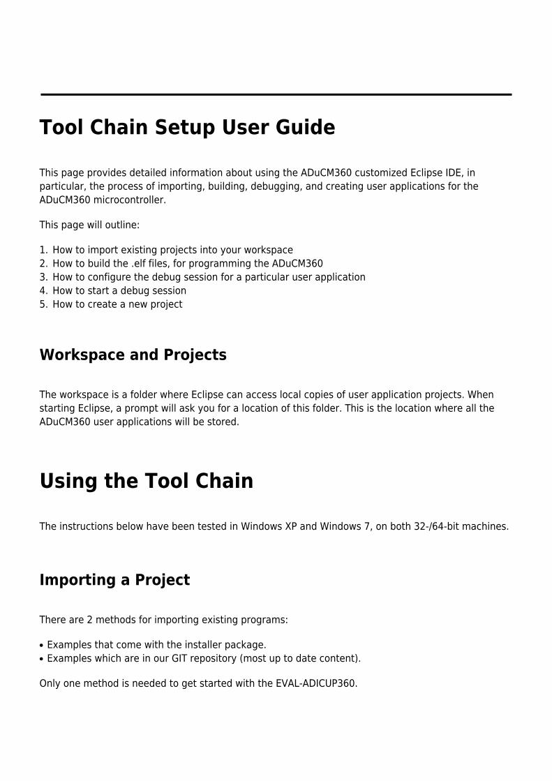
How to Import Existing Projects within the Installer Package
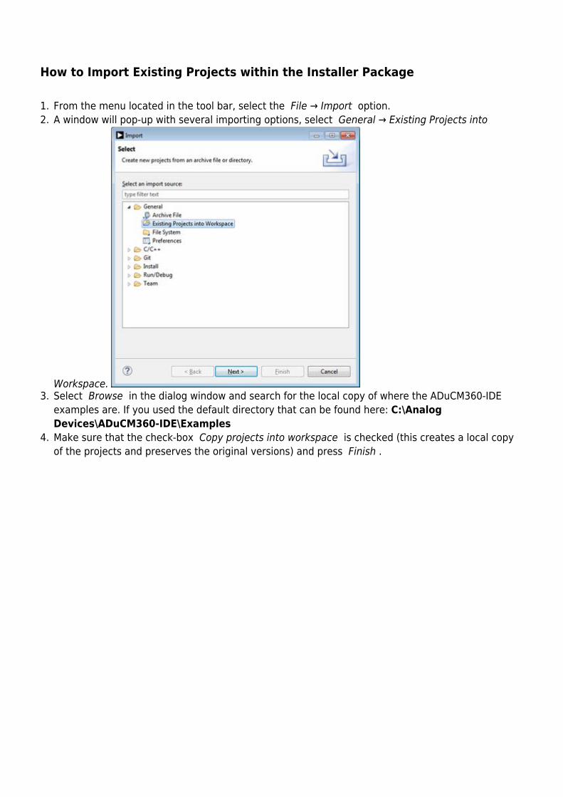
From the menu located in the tool bar, select the File → Import option.1.A window will pop-up with several importing options, select General → Existing Projects into2.
Workspace. Select Browse in the dialog window and search for the local copy of where the ADuCM360-IDE3.examples are. If you used the default directory that can be found here: C:\AnalogDevices\ADuCM360-IDE\ExamplesMake sure that the check-box Copy projects into workspace is checked (this creates a local copy4.of the projects and preserves the original versions) and press Finish .
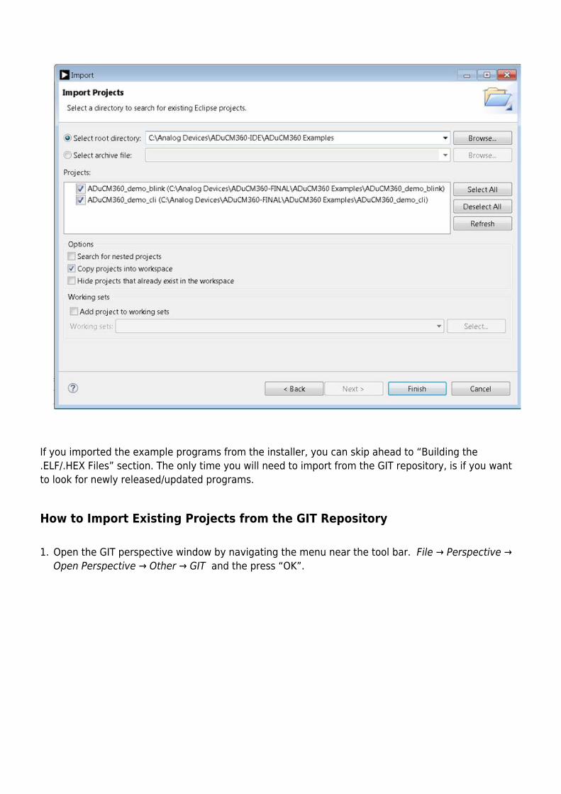
If you imported the example programs from the installer, you can skip ahead to “Building the.ELF/.HEX Files” section. The only time you will need to import from the GIT repository, is if you wantto look for newly released/updated programs.
How to Import Existing Projects from the GIT Repository
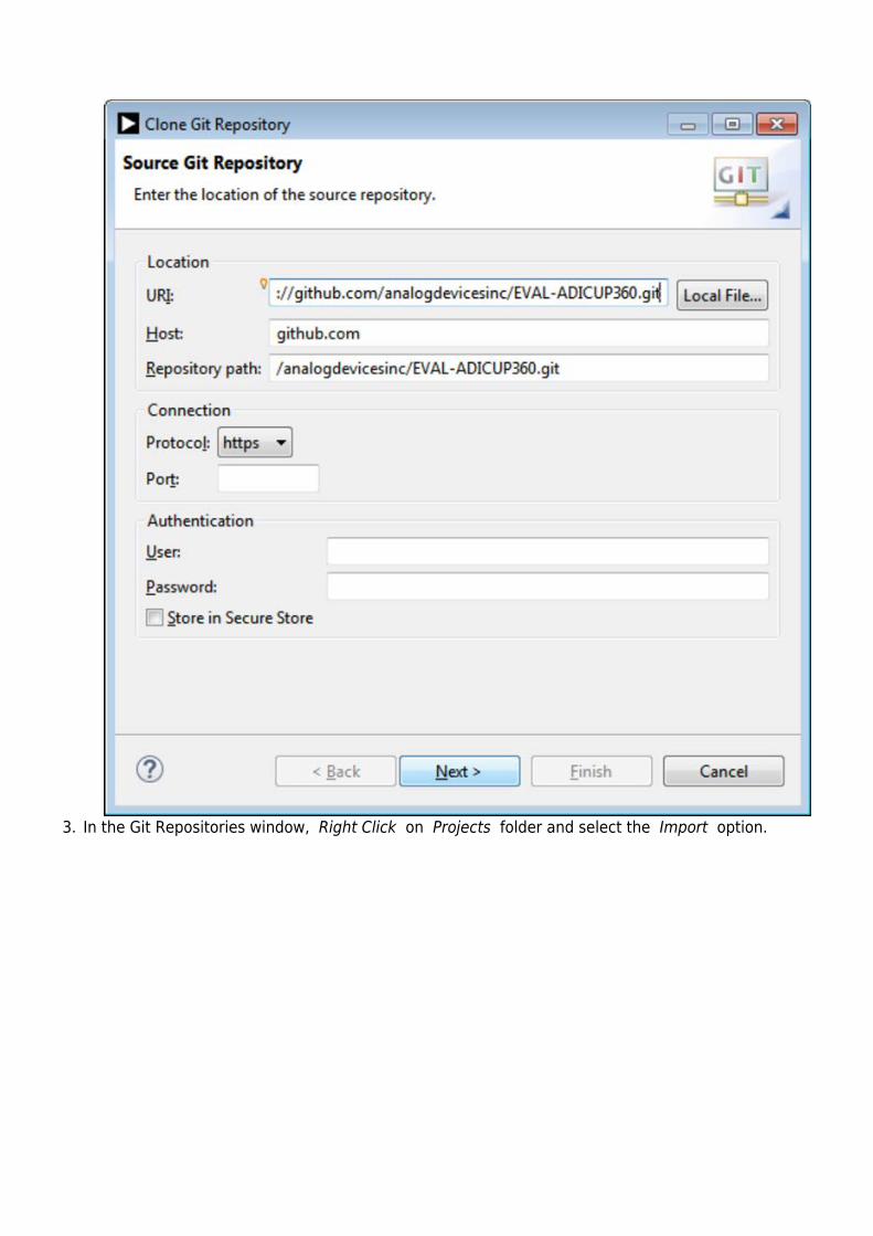
Open the GIT perspective window by navigating the menu near the tool bar. File → Perspective →1.Open Perspective → Other → GIT and the press “OK”.
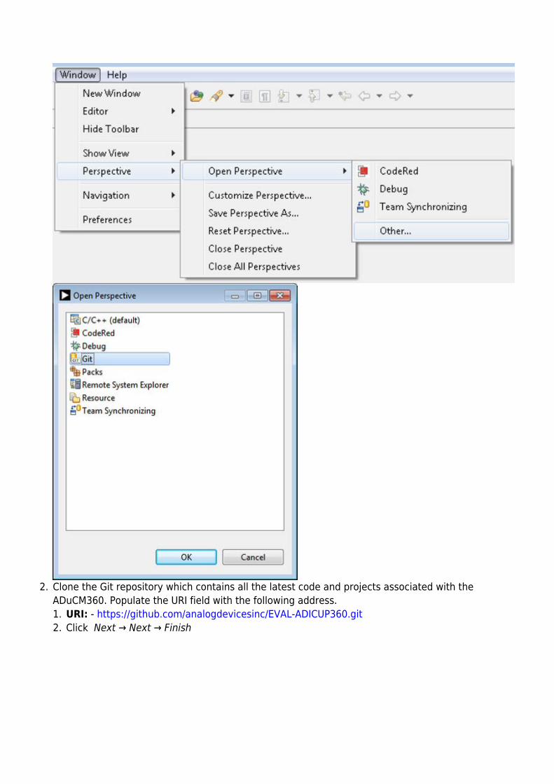
Clone the Git repository which contains all the latest code and projects associated with the2.ADuCM360. Populate the URI field with the following address.
URI: - https://github.com/analogdevicesinc/EVAL-ADICUP360.git1.Click Next → Next → Finish2.
In the Git Repositories window, Right Click on Projects folder and select the Import option.3.
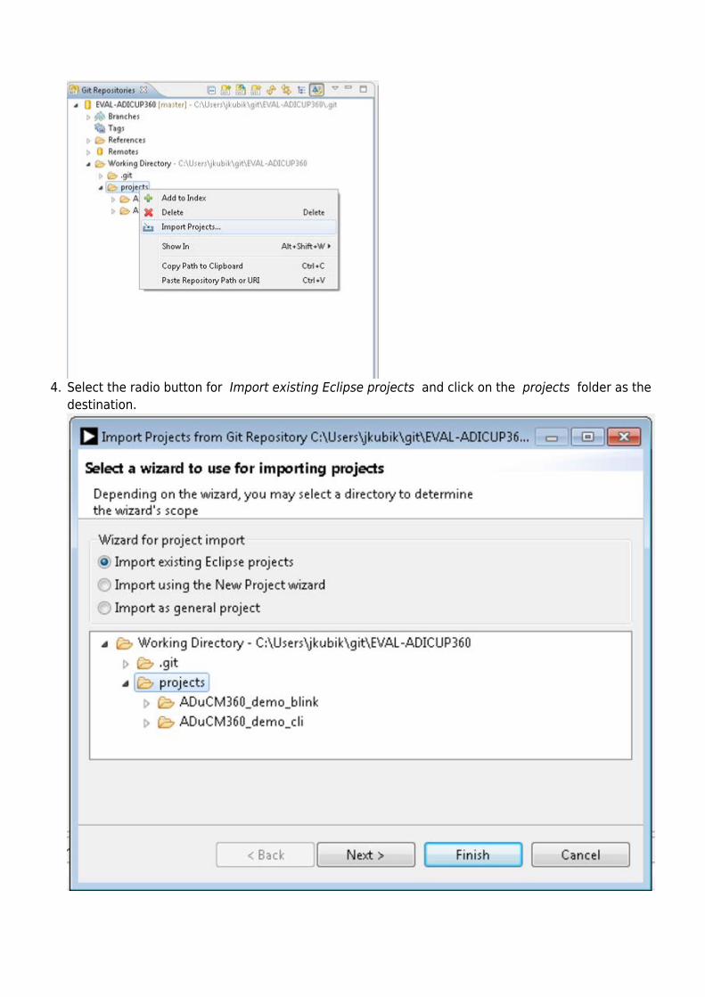
Select the radio button for Import existing Eclipse projects and click on the projects folder as the4.destination.
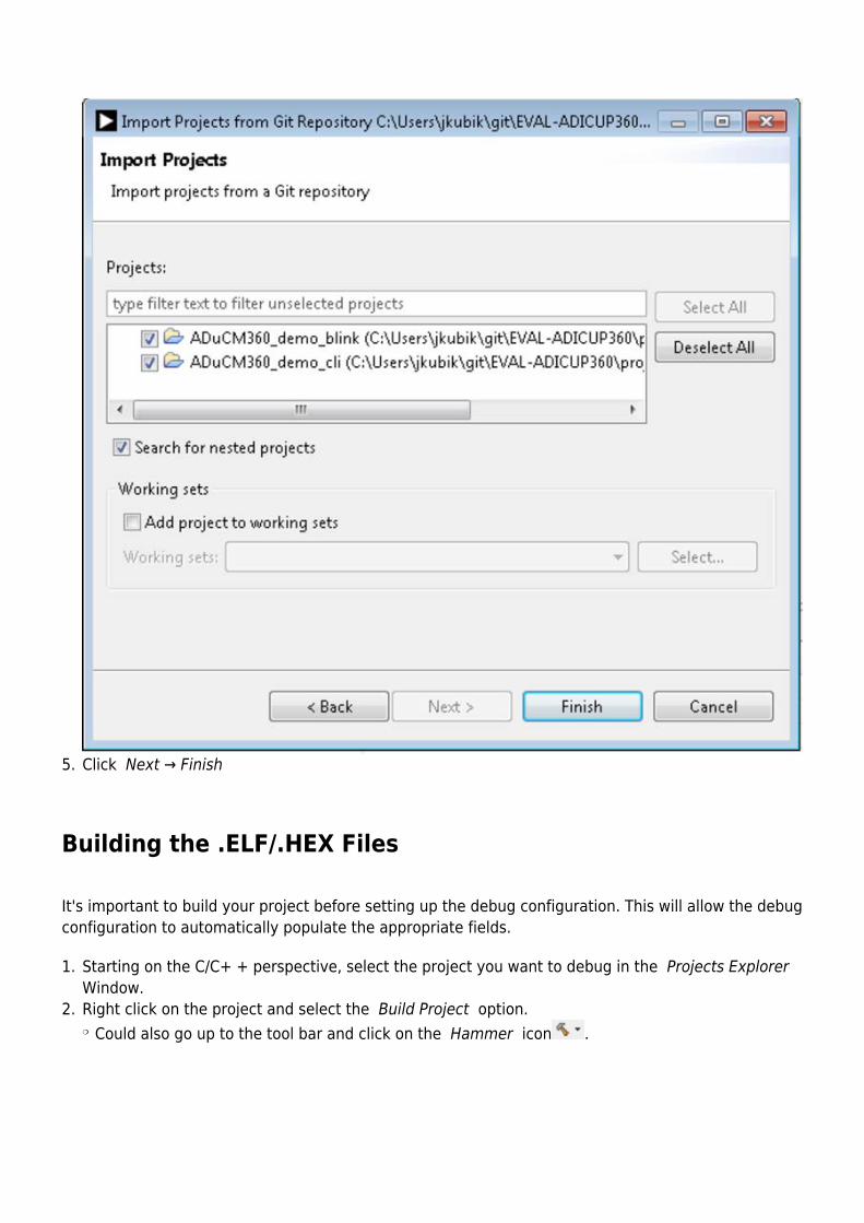
Click Next → Finish 5.
Building the .ELF/.HEX Files
It's important to build your project before setting up the debug configuration. This will allow the debugconfiguration to automatically populate the appropriate fields.
Starting on the C/C+ + perspective, select the project you want to debug in the Projects Explorer 1.Window.Right click on the project and select the Build Project option.2.
Could also go up to the tool bar and click on the Hammer icon .❍
Setting up a Debug Configuration for the Project
A new debug configuration must be set up for EACH application you intend on developing/debugging.So you will have many different debug configurations, depending on the number of programs youcreate/debug.
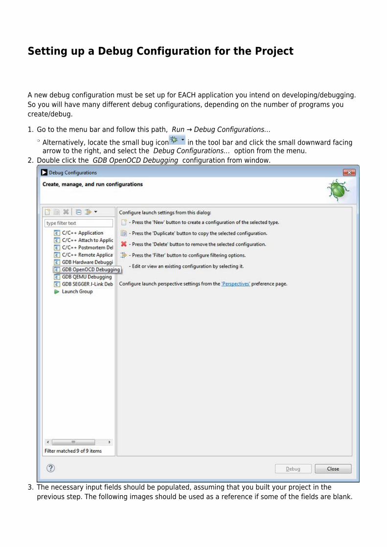
Go to the menu bar and follow this path, Run → Debug Configurations…1.Alternatively, locate the small bug icon in the tool bar and click the small downward facing❍
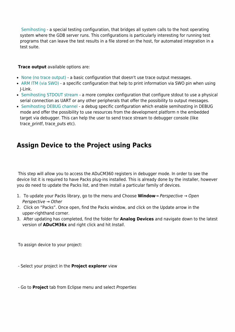
arrow to the right, and select the Debug Configurations… option from the menu.Double click the GDB OpenOCD Debugging configuration from window.2.
The necessary input fields should be populated, assuming that you built your project in the3.previous step. The following images should be used as a reference if some of the fields are blank.
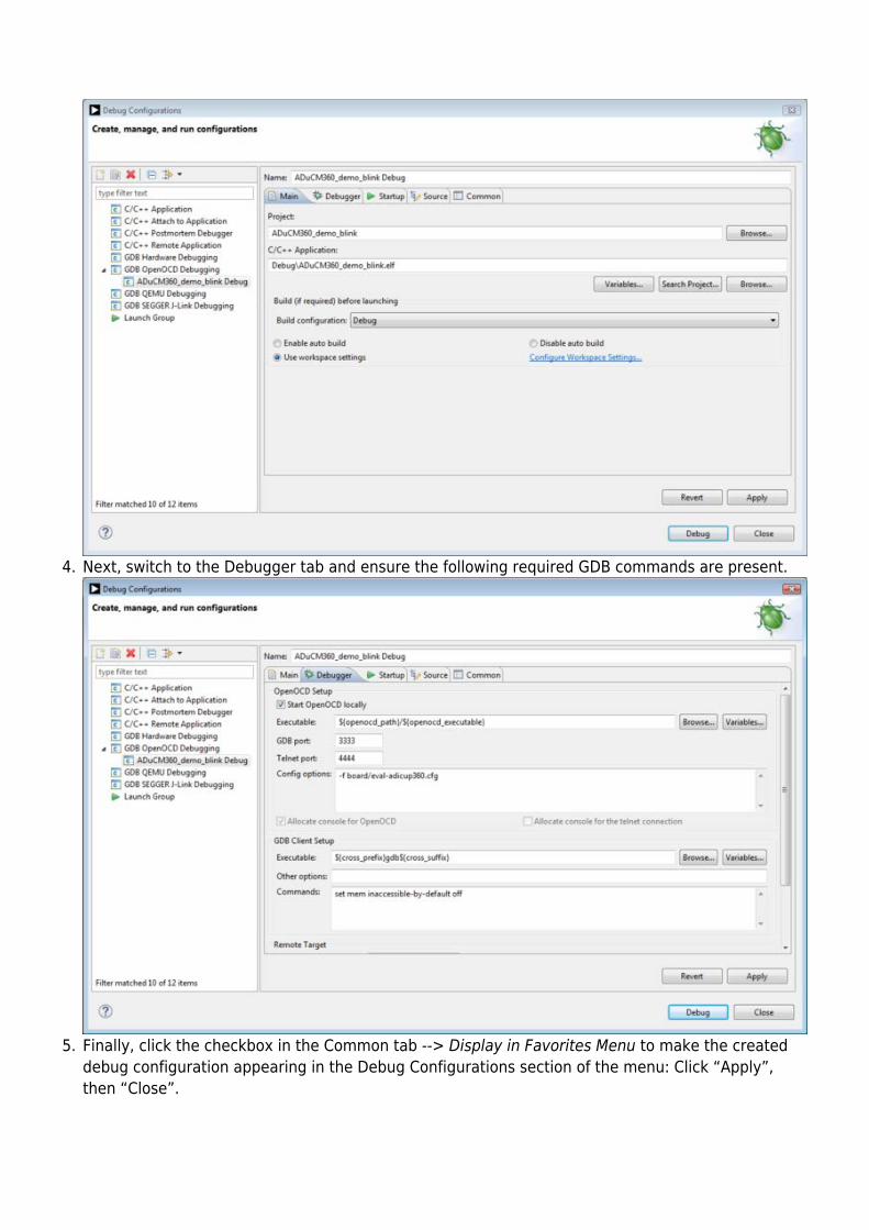
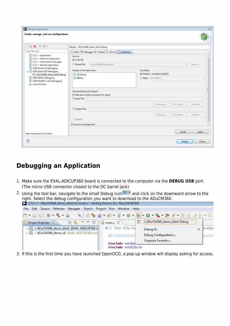
Next, switch to the Debugger tab and ensure the following required GDB commands are present.4.
Finally, click the checkbox in the Common tab --> Display in Favorites Menu to make the created5.debug configuration appearing in the Debug Configurations section of the menu: Click “Apply”,then “Close”.
Debugging an Application
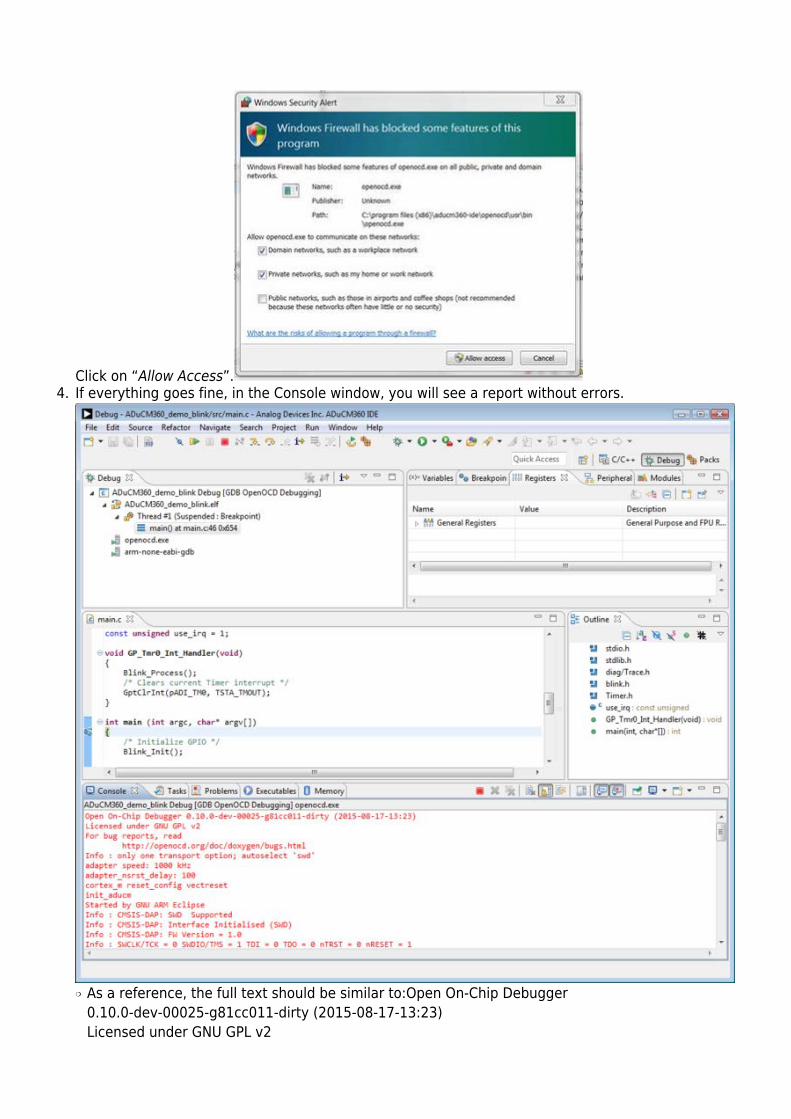
Make sure the EVAL-ADICUP360 board is connected to the computer via the DEBUG USB port.1.(The micro USB connector closest to the DC barrel jack)Using the tool bar, navigate to the small Debug icon and click on the downward arrow to the2.right. Select the debug configuration you want to download to the ADuCM360.
If this is the first time you have launched OpenOCD, a pop-up window will display asking for access.3.
Click on “Allow Access”.If everything goes fine, in the Console window, you will see a report without errors.4.
As a reference, the full text should be similar to:Open On-Chip Debugger❍
0.10.0-dev-00025-g81cc011-dirty (2015-08-17-13:23)Licensed under GNU GPL v2
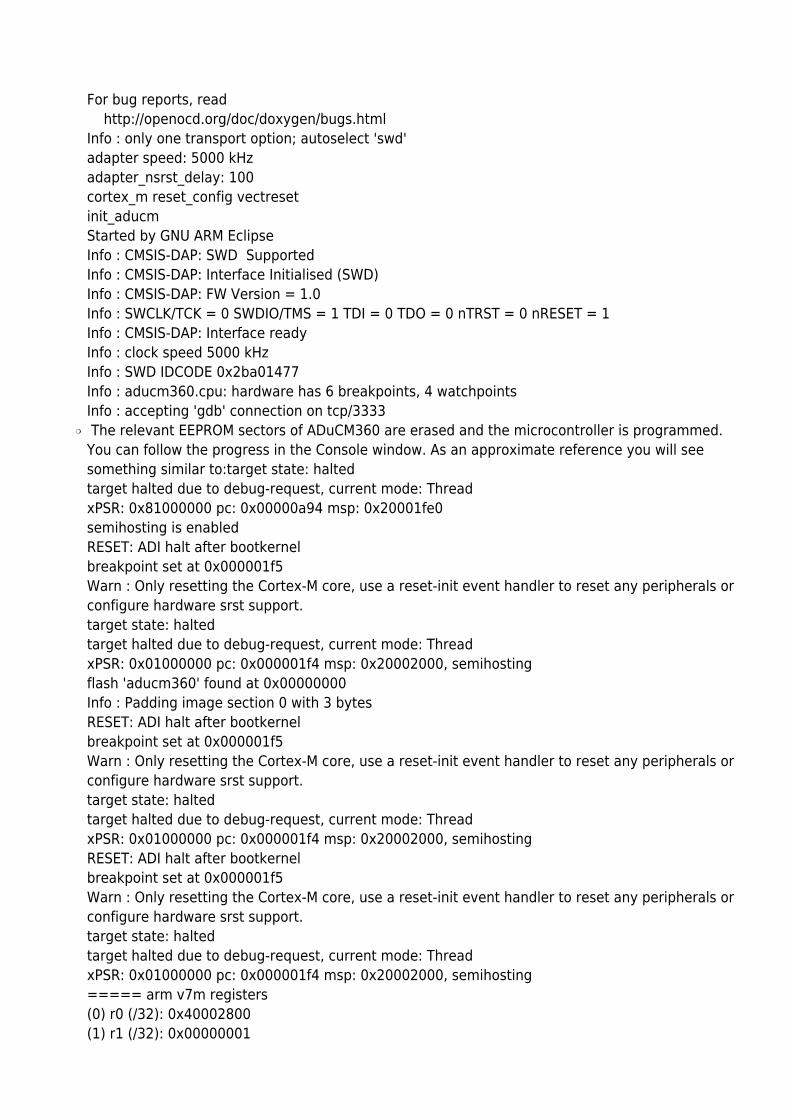
For bug reports, read http://openocd.org/doc/doxygen/bugs.htmlInfo : only one transport option; autoselect 'swd'adapter speed: 5000 kHzadapter_nsrst_delay: 100cortex_m reset_config vectresetinit_aducmStarted by GNU ARM EclipseInfo : CMSIS-DAP: SWD SupportedInfo : CMSIS-DAP: Interface Initialised (SWD)Info : CMSIS-DAP: FW Version = 1.0Info : SWCLK/TCK = 0 SWDIO/TMS = 1 TDI = 0 TDO = 0 nTRST = 0 nRESET = 1Info : CMSIS-DAP: Interface readyInfo : clock speed 5000 kHzInfo : SWD IDCODE 0x2ba01477Info : aducm360.cpu: hardware has 6 breakpoints, 4 watchpointsInfo : accepting 'gdb' connection on tcp/3333 The relevant EEPROM sectors of ADuCM360 are erased and the microcontroller is programmed.❍
You can follow the progress in the Console window. As an approximate reference you will seesomething similar to:target state: haltedtarget halted due to debug-request, current mode: ThreadxPSR: 0x81000000 pc: 0x00000a94 msp: 0x20001fe0semihosting is enabledRESET: ADI halt after bootkernelbreakpoint set at 0x000001f5Warn : Only resetting the Cortex-M core, use a reset-init event handler to reset any peripherals orconfigure hardware srst support.target state: haltedtarget halted due to debug-request, current mode: ThreadxPSR: 0x01000000 pc: 0x000001f4 msp: 0x20002000, semihostingflash 'aducm360' found at 0x00000000Info : Padding image section 0 with 3 bytesRESET: ADI halt after bootkernelbreakpoint set at 0x000001f5Warn : Only resetting the Cortex-M core, use a reset-init event handler to reset any peripherals orconfigure hardware srst support.target state: haltedtarget halted due to debug-request, current mode: ThreadxPSR: 0x01000000 pc: 0x000001f4 msp: 0x20002000, semihostingRESET: ADI halt after bootkernelbreakpoint set at 0x000001f5Warn : Only resetting the Cortex-M core, use a reset-init event handler to reset any peripherals orconfigure hardware srst support.target state: haltedtarget halted due to debug-request, current mode: ThreadxPSR: 0x01000000 pc: 0x000001f4 msp: 0x20002000, semihosting===== arm v7m registers(0) r0 (/32): 0x40002800(1) r1 (/32): 0x00000001
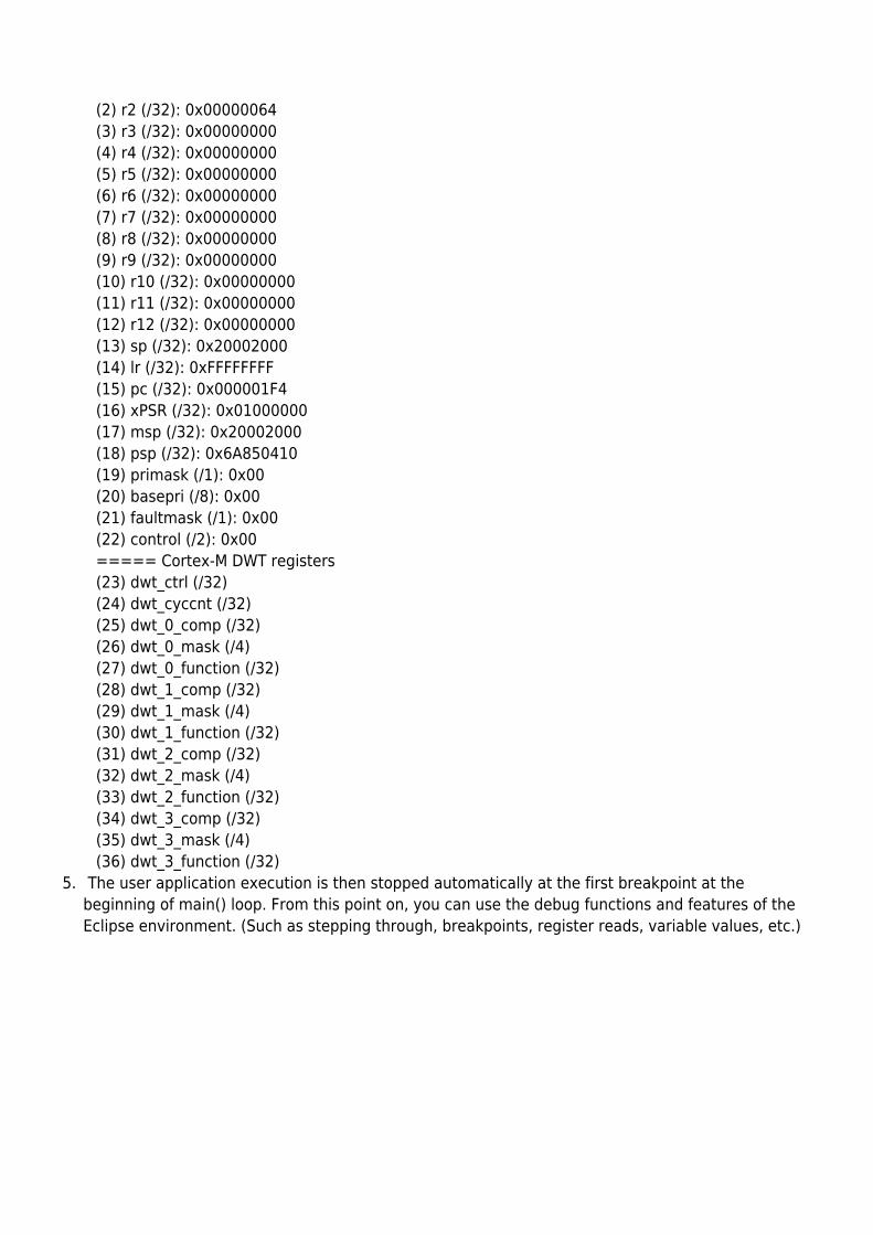
(2) r2 (/32): 0x00000064(3) r3 (/32): 0x00000000(4) r4 (/32): 0x00000000(5) r5 (/32): 0x00000000(6) r6 (/32): 0x00000000(7) r7 (/32): 0x00000000(8) r8 (/32): 0x00000000(9) r9 (/32): 0x00000000(10) r10 (/32): 0x00000000(11) r11 (/32): 0x00000000(12) r12 (/32): 0x00000000(13) sp (/32): 0x20002000(14) lr (/32): 0xFFFFFFFF(15) pc (/32): 0x000001F4(16) xPSR (/32): 0x01000000(17) msp (/32): 0x20002000(18) psp (/32): 0x6A850410(19) primask (/1): 0x00(20) basepri (/8): 0x00(21) faultmask (/1): 0x00(22) control (/2): 0x00===== Cortex-M DWT registers(23) dwt_ctrl (/32)(24) dwt_cyccnt (/32)(25) dwt_0_comp (/32)(26) dwt_0_mask (/4)(27) dwt_0_function (/32)(28) dwt_1_comp (/32)(29) dwt_1_mask (/4)(30) dwt_1_function (/32)(31) dwt_2_comp (/32)(32) dwt_2_mask (/4)(33) dwt_2_function (/32)(34) dwt_3_comp (/32)(35) dwt_3_mask (/4)(36) dwt_3_function (/32)
The user application execution is then stopped automatically at the first breakpoint at the5.beginning of main() loop. From this point on, you can use the debug functions and features of theEclipse environment. (Such as stepping through, breakpoints, register reads, variable values, etc.)
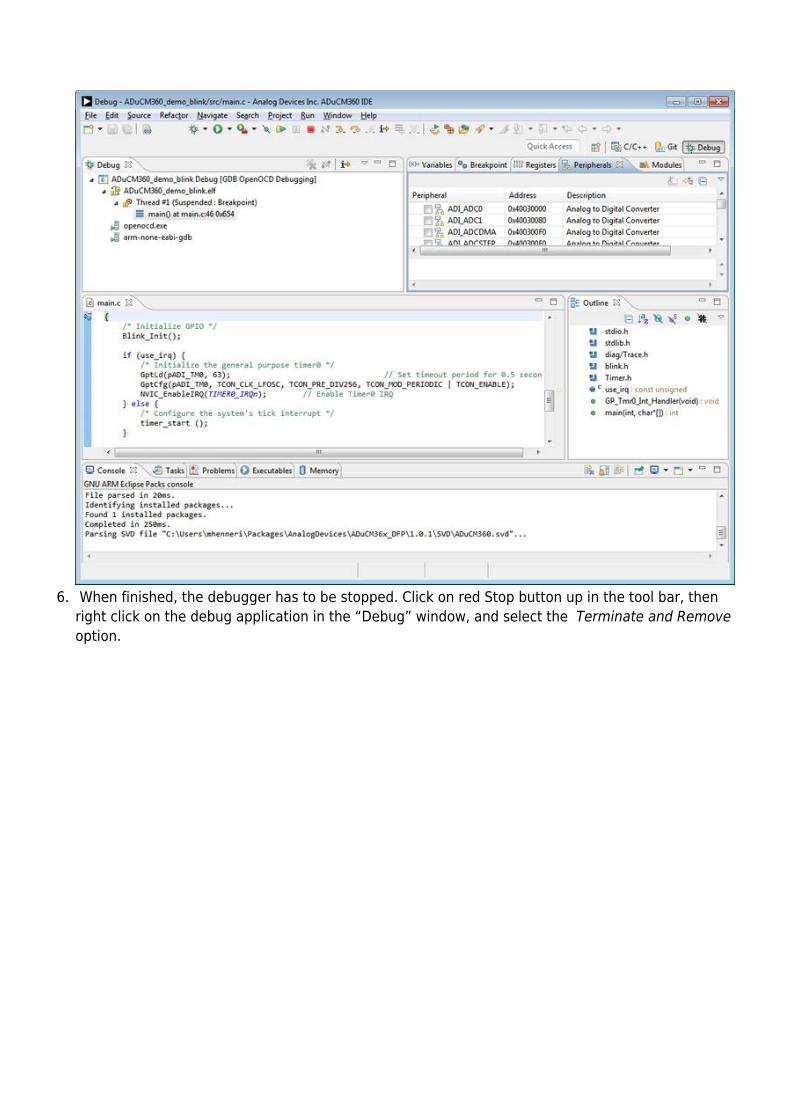
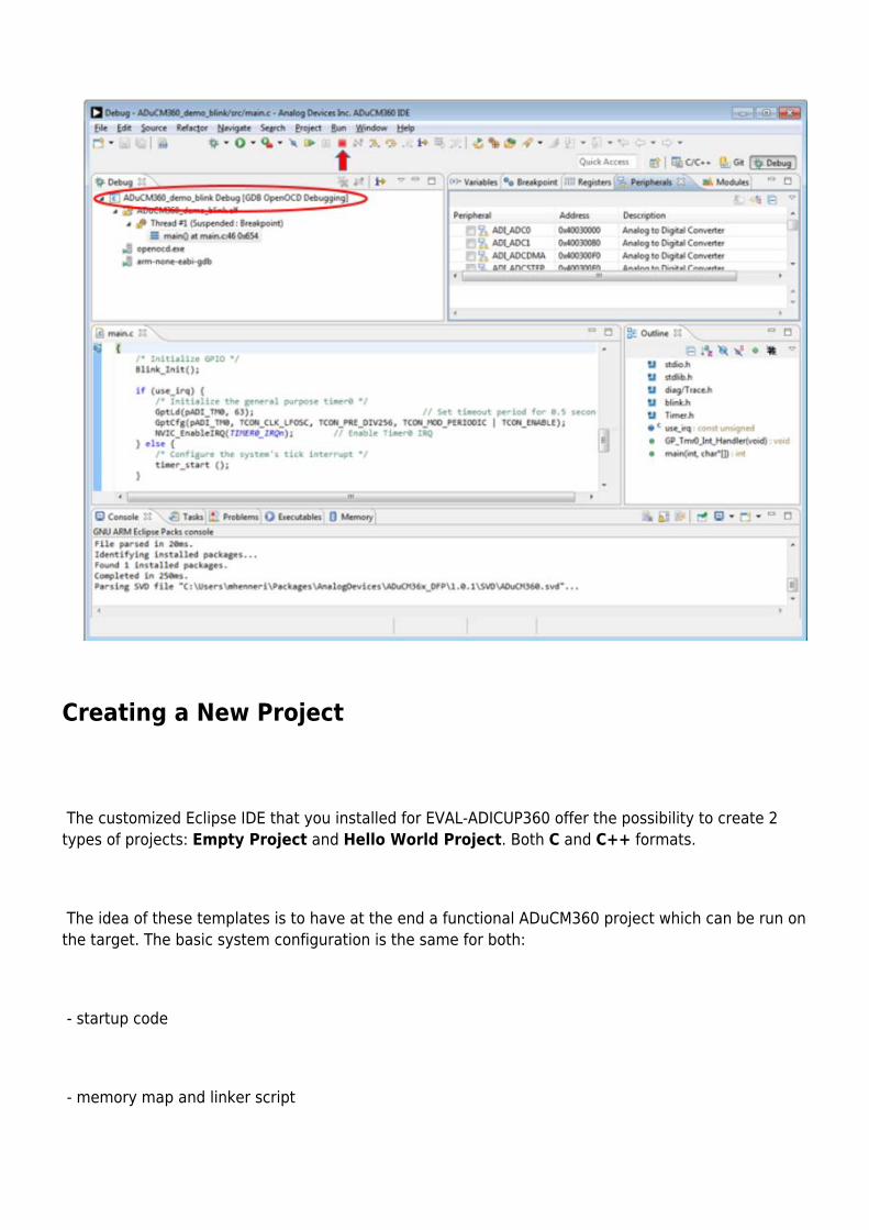
When finished, the debugger has to be stopped. Click on red Stop button up in the tool bar, then6.right click on the debug application in the “Debug” window, and select the Terminate and Remove option.
Creating a New Project
The customized Eclipse IDE that you installed for EVAL-ADICUP360 offer the possibility to create 2types of projects: Empty Project and Hello World Project. Both C and C++ formats.
The idea of these templates is to have at the end a functional ADuCM360 project which can be run onthe target. The basic system configuration is the same for both:
- startup code
- memory map and linker script
- system clock configuration
- disabling watchdog
- enabling clocks for all peripherals
- low drivers libraries for ADuCM360 microcontroller
The differences are regarding the complexity of the main() function: the Empty template provide anempty main() function, being in this way a good choose when you want to start your ADuCM360project from the scratch; the Hello World template is for more complex projects. It provide 1 sectime base and different possibilities to display an output message to the user.
See below how to create the C projects for EVAL-ADICUP360 board. The same steps being availablefor C++ projects as well.
To create a new project, go to the menu bar and find File → New → C Project.1.
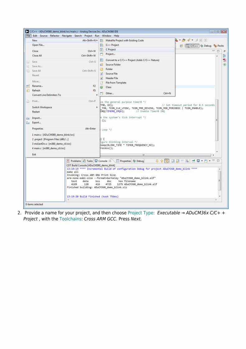
Provide a name for your project, and then choose Project Type: Executable → ADuCM36x C/C+ +2.Project , with the Toolchains: Cross ARM GCC. Press Next.
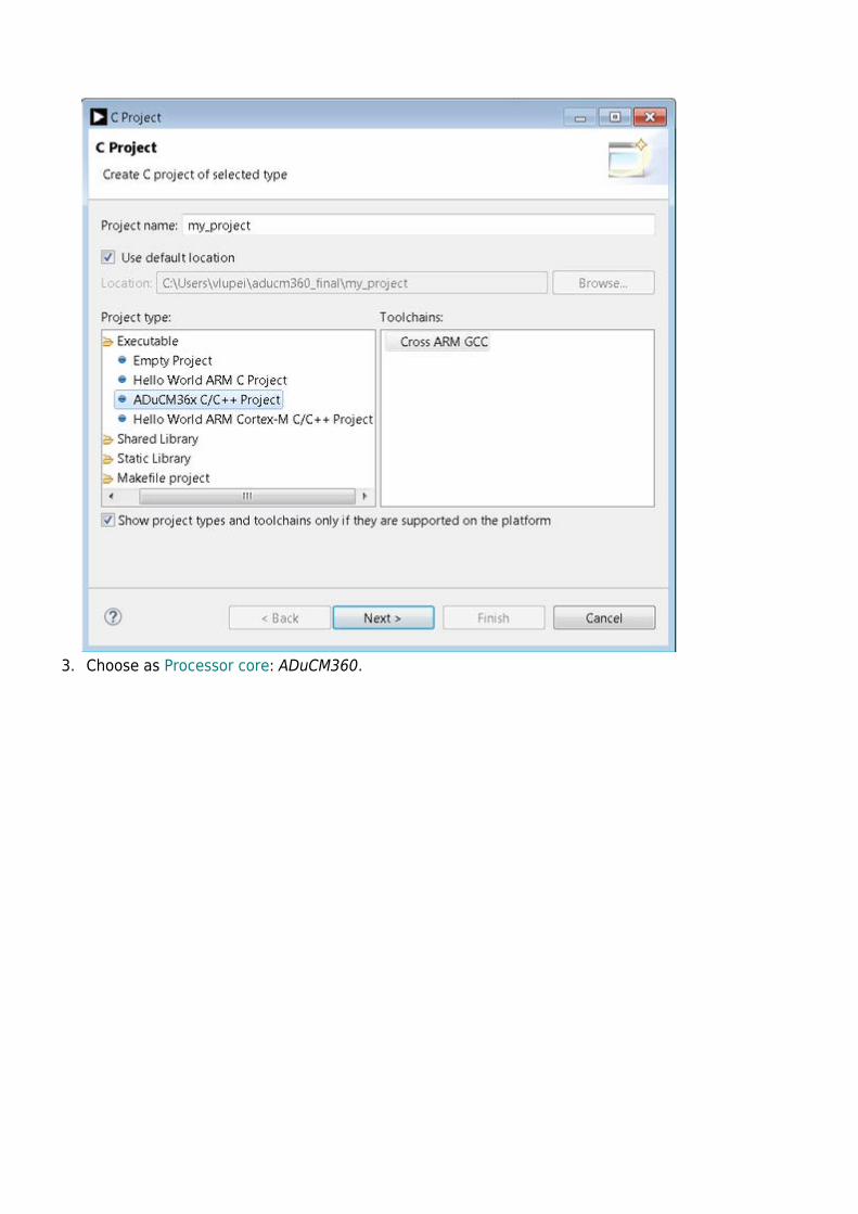
Choose as Processor core: ADuCM360.3.
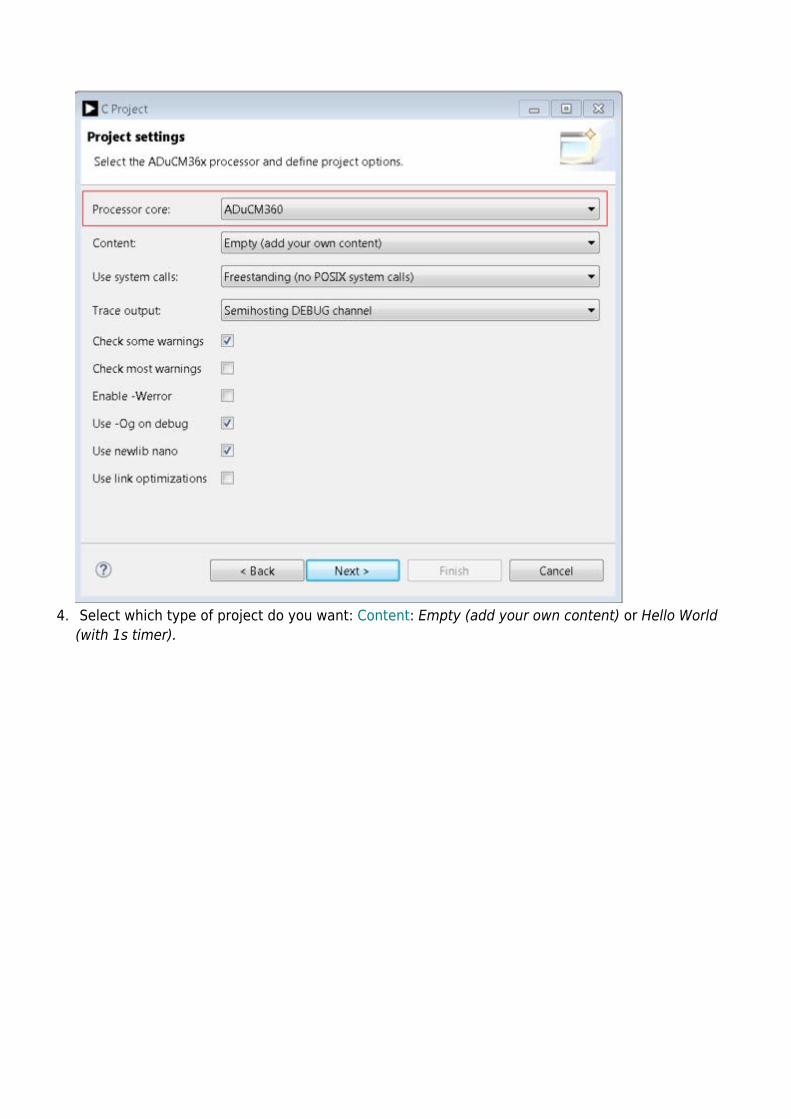
Select which type of project do you want: Content: Empty (add your own content) or Hello World4.(with 1s timer).
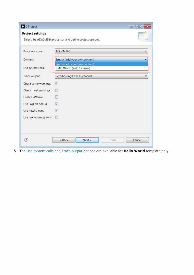
The Use system calls and Trace output options are available for Hello World template only.5.
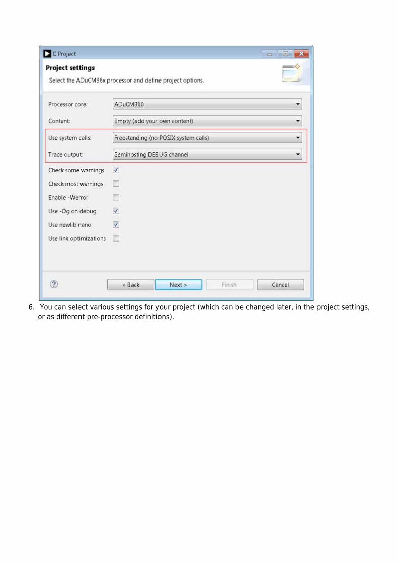
You can select various settings for your project (which can be changed later, in the project settings,6.or as different pre-processor definitions).
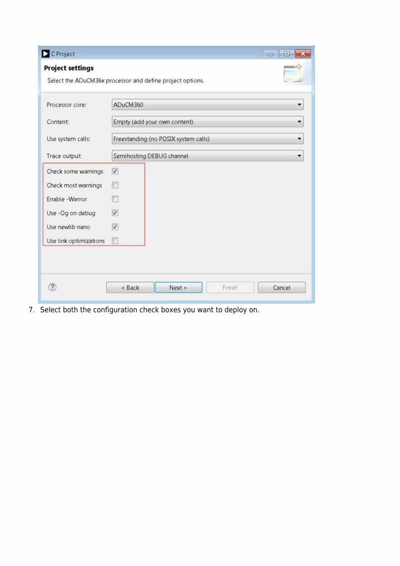
Select both the configuration check boxes you want to deploy on.7.
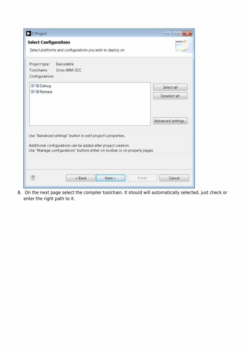
On the next page select the compiler toolchain. It should will automatically selected, just check or8.enter the right path to it.
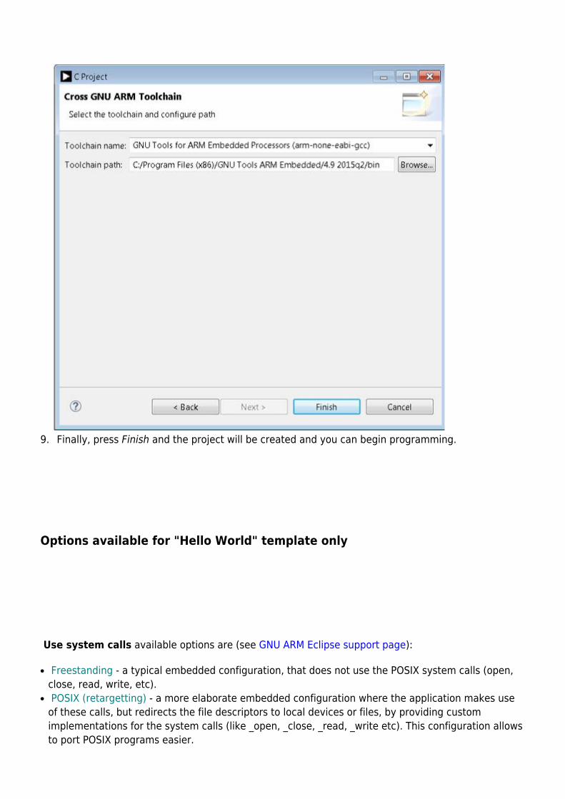
Finally, press Finish and the project will be created and you can begin programming.9.
Options available for "Hello World" template only
Use system calls available options are (see GNU ARM Eclipse support page):
Freestanding - a typical embedded configuration, that does not use the POSIX system calls (open,●
close, read, write, etc). POSIX (retargetting) - a more elaborate embedded configuration where the application makes use●
of these calls, but redirects the file descriptors to local devices or files, by providing customimplementations for the system calls (like _open, _close, _read, _write etc). This configuration allowsto port POSIX programs easier.
Semihosting - a special testing configuration, that bridges all system calls to the host operatingsystem where the GDB server runs. This configurations is particularly interesting for running testprograms that can leave the test results in a file stored on the host, for automated integration in atest suite.
Trace output available options are:
None (no trace output) - a basic configuration that doesn't use trace output messages.●
ARM ITM (via SWO) - a specific configuration that help to print information via SWO pin when using●
J-Link. Semihosting STDOUT stream - a more complex configuration that configure stdout to use a physical●
serial connection as UART or any other peripherals that offer the possibility to output messages. Semihosting DEBUG channel - a debug specific configuration which enable semihosting in DEBUG●
mode and offer the possibility to use resources from the development platform n the embeddedtarget via debugger. This can help the user to send trace stream to debugger console (liketrace_printf, trace_puts etc).
Assign Device to the Project using Packs
This step will allow you to access the ADuCM360 registers in debugger mode. In order to see thedevice list it is required to have Packs plug-ins installed. This is already done by the installer, howeveryou do need to update the Packs list, and then install a particular family of devices.
To update your Packs library, go to the menu and Choose Window→ Perspective → Open1.Perspective → Other Click on “Packs”. Once open, find the Packs window, and click on the Update arrow in the2.upper-righthand corner. After updating has completed, find the folder for Analog Devices and navigate down to the latest3.version of ADuCM36x and right click and hit Install.
To assign device to your project:
- Select your project in the Project explorer view
- Go to Project tab from Eclipse menu and select Properties
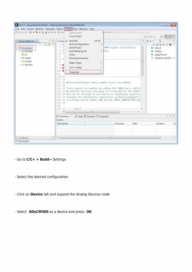
- Go to C/C+ + Build→ Settings
- Select the desired configuration
- Click on Device tab and expand the Analog Devices node
- Select ADuCM360 as a device and press OK
Hardware
This chapter contains hardware-related information about the base board and the various shields.Each sub-section contains a general description of the board, detailed description of the connectors,jumpers, and buttons (if any). It also provides links to the Schematics, Bill of materials, designprojects, and Technical documentation. It also gives internal links to the provided example demosoftware projects.
The following boards are currently available:
EVAL-ADICUP360 Base Board●
EVAL-CN0216-ARDZ Shield●
EVAL-CN0357-ARDZ Shield●
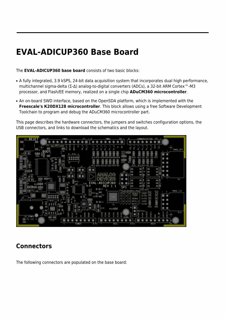
EVAL-ADICUP360 Base Board
The EVAL-ADICUP360 base board consists of two basic blocks:
A fully integrated, 3.9 kSPS, 24-bit data acquisition system that incorporates dual high performance,●
multichannel sigma-delta (Σ-Δ) analog-to-digital converters (ADCs), a 32-bit ARM Cortex™-M3processor, and Flash/EE memory, realized on a single chip ADuCM360 microcontroller.
An on-board SWD interface, based on the OpenSDA platform, which is implemented with the●
Freescale's К20DX128 microcontroller. This block allows using a free Software DevelopmentToolchain to program and debug the ADuCM360 microcontroller part.
This page describes the hardware connectors, the jumpers and switches configuration options, theUSB connectors, and links to download the schematics and the layout.
Connectors
The following connectors are populated on the base board:
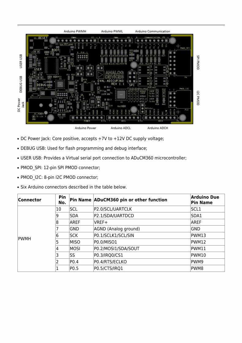
DC Power Jack: Core positive, accepts +7V to +12V DC supply voltage;●
DEBUG USB: Used for flash programming and debug interface;●
USER USB: Provides a Virtual serial port connection to ADuCM360 microcontroller;●
PMOD_SPI: 12-pin SPI PMOD connector;●
PMOD_I2C: 8-pin I2C PMOD connector;●
Six Arduino connectors described in the table below.●
Connector PinNo. Pin Name ADuCM360 pin or other function Arduino Due
Pin Name
PWMH
10 SCL P2.0/SCL/UARTCLK SCL19 SDA P2.1/SDA/UARTDCD SDA18 AREF VREF+ AREF7 GND AGND (Analog ground) GND6 SCK P0.1/SCLK1/SCL/SIN PWM135 MISO P0.0/MISO1 PWM124 MOSI P0.2/MOSI1/SDA/SOUT PWM113 SS P0.3/IRQ0/CS1 PWM102 P0.4 P0.4/RTS/ECLKO PWM91 P0.5 P0.5/CTS/IRQ1 PWM8
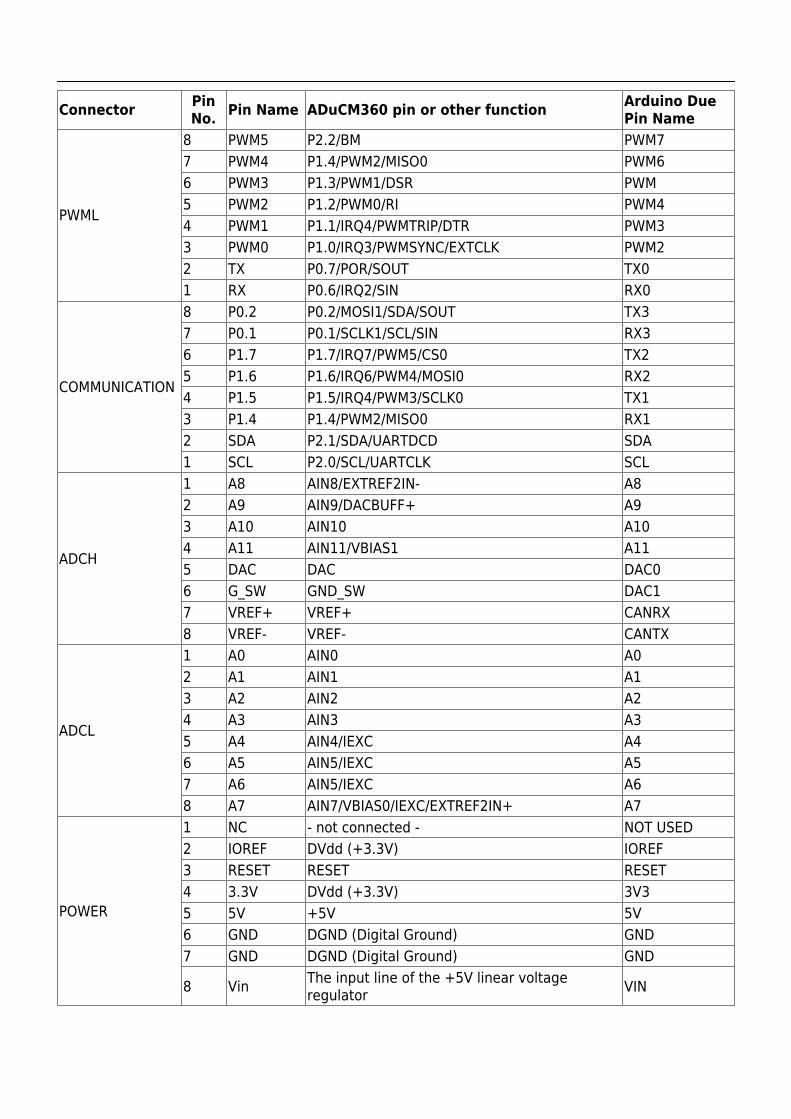
Connector PinNo. Pin Name ADuCM360 pin or other function Arduino Due
Pin Name
PWML
8 PWM5 P2.2/BM PWM77 PWM4 P1.4/PWM2/MISO0 PWM66 PWM3 P1.3/PWM1/DSR PWM5 PWM2 P1.2/PWM0/RI PWM44 PWM1 P1.1/IRQ4/PWMTRIP/DTR PWM33 PWM0 P1.0/IRQ3/PWMSYNC/EXTCLK PWM22 TX P0.7/POR/SOUT TX01 RX P0.6/IRQ2/SIN RX0
COMMUNICATION
8 P0.2 P0.2/MOSI1/SDA/SOUT TX37 P0.1 P0.1/SCLK1/SCL/SIN RX36 P1.7 P1.7/IRQ7/PWM5/CS0 TX25 P1.6 P1.6/IRQ6/PWM4/MOSI0 RX24 P1.5 P1.5/IRQ4/PWM3/SCLK0 TX13 P1.4 P1.4/PWM2/MISO0 RX12 SDA P2.1/SDA/UARTDCD SDA1 SCL P2.0/SCL/UARTCLK SCL
ADCH
1 A8 AIN8/EXTREF2IN- A82 A9 AIN9/DACBUFF+ A93 A10 AIN10 A104 A11 AIN11/VBIAS1 A115 DAC DAC DAC06 G_SW GND_SW DAC17 VREF+ VREF+ CANRX8 VREF- VREF- CANTX
ADCL
1 A0 AIN0 A02 A1 AIN1 A13 A2 AIN2 A24 A3 AIN3 A35 A4 AIN4/IEXC A46 A5 AIN5/IEXC A57 A6 AIN5/IEXC A68 A7 AIN7/VBIAS0/IEXC/EXTREF2IN+ A7
POWER
1 NC - not connected - NOT USED2 IOREF DVdd (+3.3V) IOREF3 RESET RESET RESET4 3.3V DVdd (+3.3V) 3V35 5V +5V 5V6 GND DGND (Digital Ground) GND7 GND DGND (Digital Ground) GND
8 Vin The input line of the +5V linear voltageregulator VIN
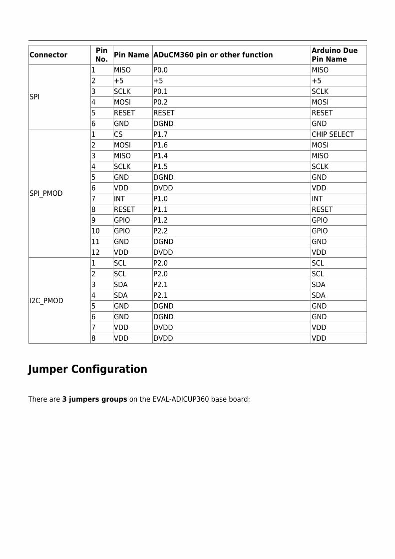
Connector PinNo. Pin Name ADuCM360 pin or other function Arduino Due
Pin Name
SPI
1 MISO P0.0 MISO2 +5 +5 +53 SCLK P0.1 SCLK4 MOSI P0.2 MOSI5 RESET RESET RESET6 GND DGND GND
SPI_PMOD
1 CS P1.7 CHIP SELECT2 MOSI P1.6 MOSI3 MISO P1.4 MISO4 SCLK P1.5 SCLK5 GND DGND GND6 VDD DVDD VDD7 INT P1.0 INT8 RESET P1.1 RESET9 GPIO P1.2 GPIO10 GPIO P2.2 GPIO11 GND DGND GND12 VDD DVDD VDD
I2C_PMOD
1 SCL P2.0 SCL2 SCL P2.0 SCL3 SDA P2.1 SDA4 SDA P2.1 SDA5 GND DGND GND6 GND DGND GND7 VDD DVDD VDD8 VDD DVDD VDD
Jumper Configuration
There are 3 jumpers groups on the EVAL-ADICUP360 base board:
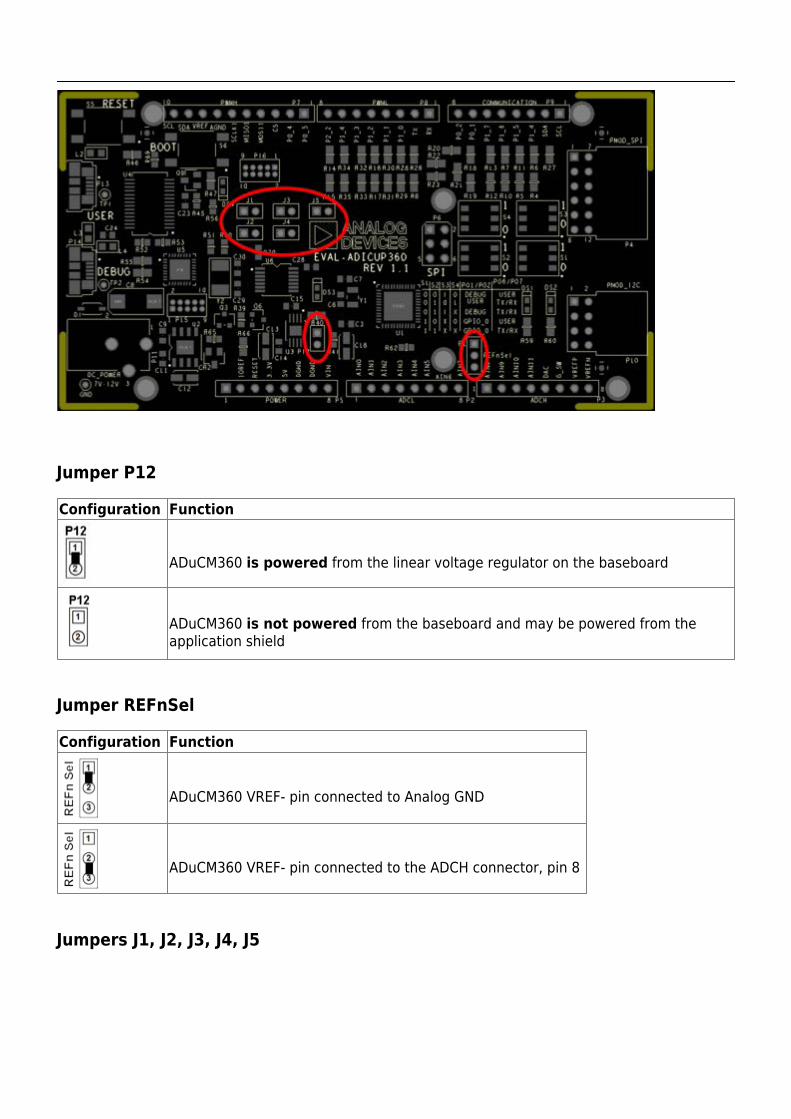
Jumper P12
Configuration Function
ADuCM360 is powered from the linear voltage regulator on the baseboard
ADuCM360 is not powered from the baseboard and may be powered from theapplication shield
Jumper REFnSel
Configuration Function
ADuCM360 VREF- pin connected to Analog GND
ADuCM360 VREF- pin connected to the ADCH connector, pin 8
Jumpers J1, J2, J3, J4, J5
Configuration Function
ADuCM360's UART pins are connected to the Virtual serial port of the Debugadapter
ADuCM360's UART pins are not connected to the Virtual serial port of theDebug adapter
ADuCM360's SWD lines are connected to the Debug adapter. ADuCM360 canbe programmed
ADuCM360's SWD lines are not connected to the Debug adapter. ADuCM360cannot be programmed
ADuCM360's RESET line is connected to the Debug adapter. The button B1 canbe used to invoke the Debug adapter's Bootloader.
ADuCM360's RESET line is not connected to the Debug adapter. The button B1is just an ADuCM360 reset button.
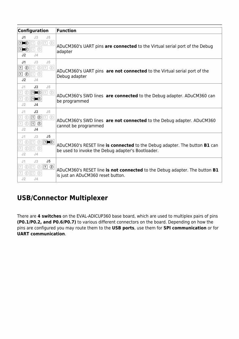
USB/Connector Multiplexer
There are 4 switches on the EVAL-ADICUP360 base board, which are used to multiplex pairs of pins(P0.1/P0.2, and P0.6/P0.7) to various different connectors on the board. Depending on how thepins are configured you may route them to the USB ports, use them for SPI communication or forUART communication.
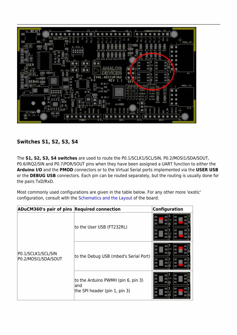
Switches S1, S2, S3, S4
The S1, S2, S3, S4 switches are used to route the P0.1/SCLK1/SCL/SIN, P0.2/MOSI1/SDA/SOUT,P0.6/IRQ2/SIN and P0.7/POR/SOUT pins when they have been assigned a UART function to either theArduino I/O and the PMOD connectors or to the Virtual Serial ports implemented via the USER USBor the DEBUG USB connectors. Each pin can be routed separately, but the routing is usually done forthe pairs TxD/RxD.
Most commonly used configurations are given in the table below. For any other more 'exotic'configuration, consult with the Schematics and the Layout of the board.
ADuCM360's pair of pins Required connection Configuration
P0.1/SCLK1/SCL/SINP0.2/MOSI1/SDA/SOUT
to the User USB (FT232RL)
to the Debug USB (mbed's Serial Port)
to the Arduino PWMH (pin 6, pin 3)andthe SPI header (pin 1, pin 3)
ADuCM360's pair of pins Required connection Configuration
P0.6/IRQ2/SINP0.7/POR/SOUT
to the User USB (FT232RL)
to the Arduino PWML (pin 1, pin 2)
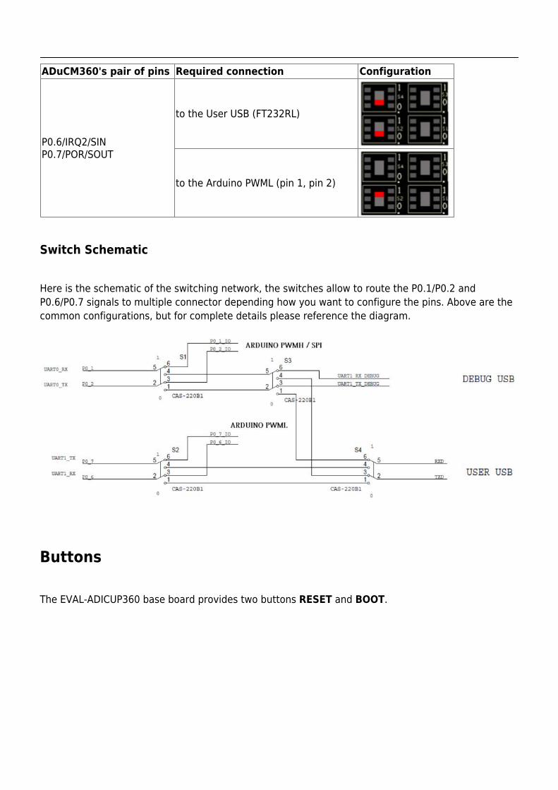
Switch Schematic
Here is the schematic of the switching network, the switches allow to route the P0.1/P0.2 andP0.6/P0.7 signals to multiple connector depending how you want to configure the pins. Above are thecommon configurations, but for complete details please reference the diagram.
Buttons
The EVAL-ADICUP360 base board provides two buttons RESET and BOOT.
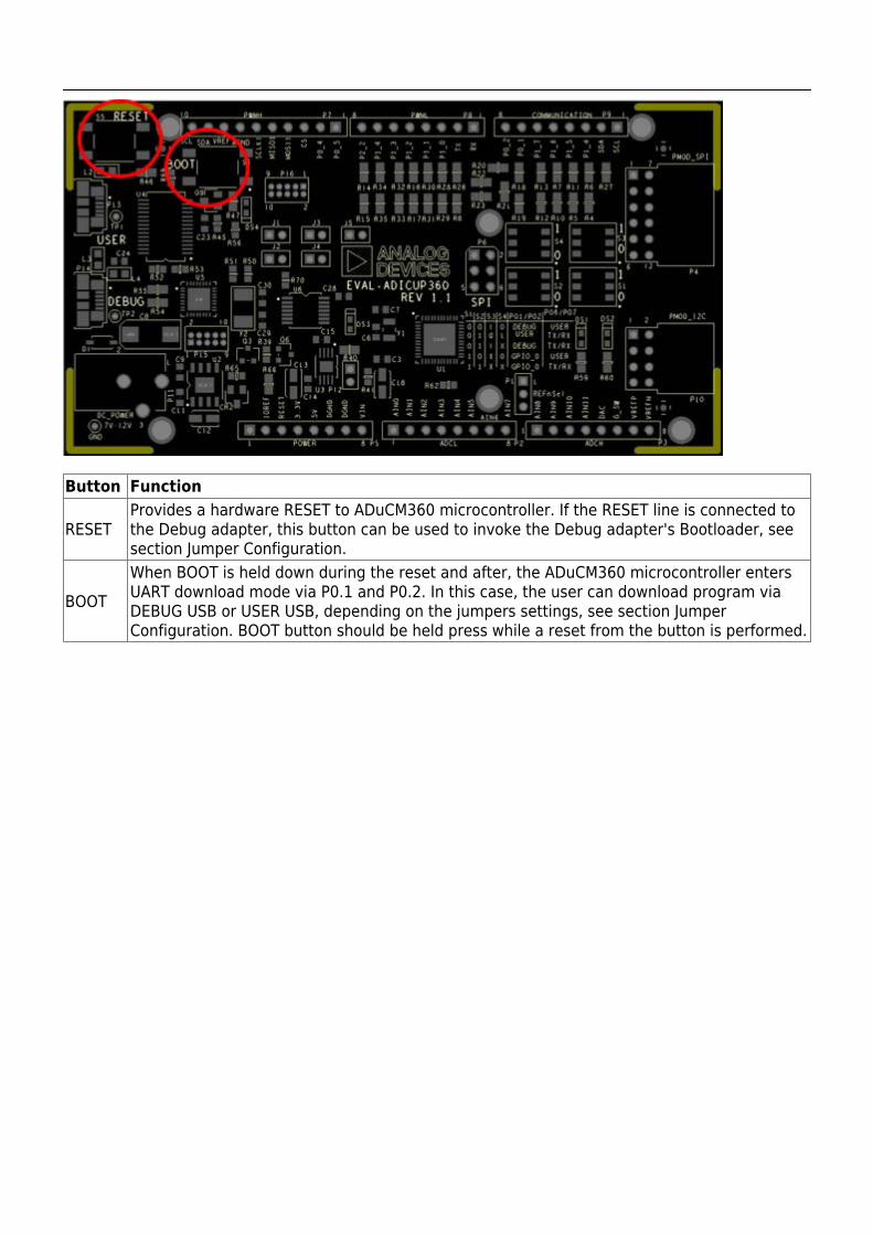
Button Function
RESETProvides a hardware RESET to ADuCM360 microcontroller. If the RESET line is connected tothe Debug adapter, this button can be used to invoke the Debug adapter's Bootloader, seesection Jumper Configuration.
BOOTWhen BOOT is held down during the reset and after, the ADuCM360 microcontroller entersUART download mode via P0.1 and P0.2. In this case, the user can download program viaDEBUG USB or USER USB, depending on the jumpers settings, see section JumperConfiguration. BOOT button should be held press while a reset from the button is performed.
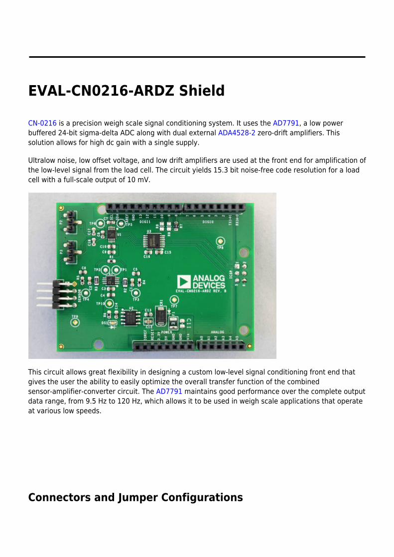
EVAL-CN0216-ARDZ Shield
CN-0216 is a precision weigh scale signal conditioning system. It uses the AD7791, a low powerbuffered 24-bit sigma-delta ADC along with dual external ADA4528-2 zero-drift amplifiers. Thissolution allows for high dc gain with a single supply.
Ultralow noise, low offset voltage, and low drift amplifiers are used at the front end for amplification ofthe low-level signal from the load cell. The circuit yields 15.3 bit noise-free code resolution for a loadcell with a full-scale output of 10 mV.
This circuit allows great flexibility in designing a custom low-level signal conditioning front end thatgives the user the ability to easily optimize the overall transfer function of the combinedsensor-amplifier-converter circuit. The AD7791 maintains good performance over the complete outputdata range, from 9.5 Hz to 120 Hz, which allows it to be used in weigh scale applications that operateat various low speeds.
Connectors and Jumper Configurations
PICTURE OF THE BOARD FILE with JUMPERS AND CONNECTORS HIGHLIGHTED
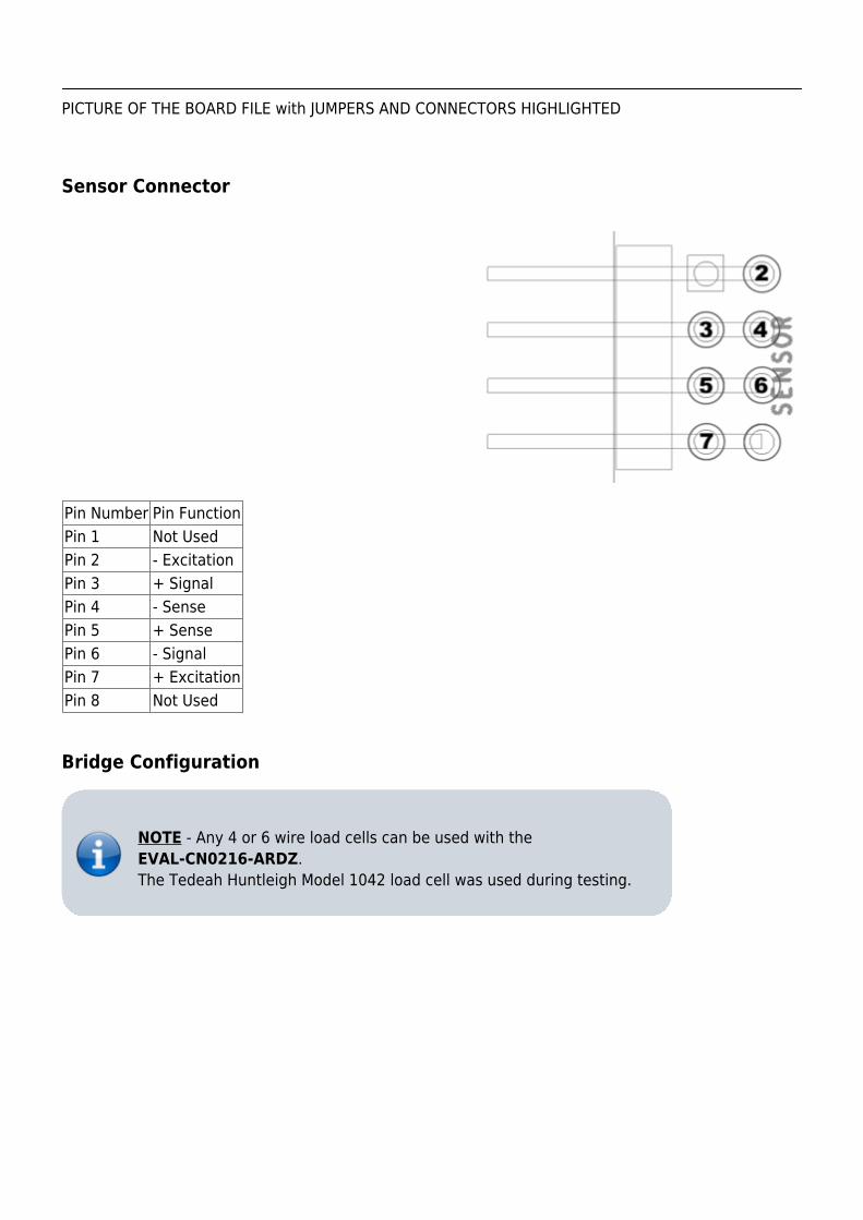
Sensor Connector
Pin Number Pin FunctionPin 1 Not UsedPin 2 - ExcitationPin 3 + SignalPin 4 - SensePin 5 + SensePin 6 - SignalPin 7 + ExcitationPin 8 Not Used
Bridge Configuration
NOTE - Any 4 or 6 wire load cells can be used with theEVAL-CN0216-ARDZ.The Tedeah Huntleigh Model 1042 load cell was used during testing.
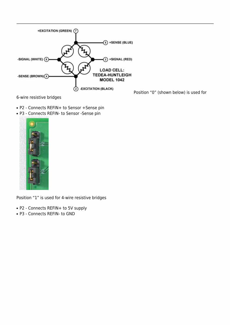
Position “0” (shown below) is used for6-wire resistive bridges
P2 - Connects REFIN+ to Sensor +Sense pin●
P3 - Connects REFIN- to Sensor -Sense pin●
Position “1” is used for 4-wire resistive bridges
P2 - Connects REFIN+ to 5V supply●
P3 - Connects REFIN- to GND●
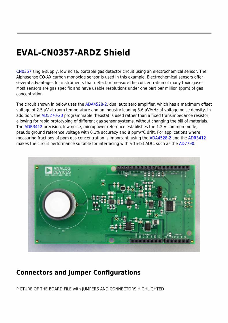
EVAL-CN0357-ARDZ Shield
CN0357 single-supply, low noise, portable gas detector circuit using an electrochemical sensor. TheAlphasense CO-AX carbon monoxide sensor is used in this example. Electrochemical sensors offerseveral advantages for instruments that detect or measure the concentration of many toxic gases.Most sensors are gas specific and have usable resolutions under one part per million (ppm) of gasconcentration.
The circuit shown in below uses the ADA4528-2, dual auto zero amplifier, which has a maximum offsetvoltage of 2.5 µV at room temperature and an industry leading 5.6 µV/√Hz of voltage noise density. Inaddition, the AD5270-20 programmable rheostat is used rather than a fixed transimpedance resistor,allowing for rapid prototyping of different gas sensor systems, without changing the bill of materials.The ADR3412 precision, low noise, micropower reference establishes the 1.2 V common-mode,pseudo ground reference voltage with 0.1% accuracy and 8 ppm/°C drift. For applications wheremeasuring fractions of ppm gas concentration is important, using the ADA4528-2 and the ADR3412makes the circuit performance suitable for interfacing with a 16-bit ADC, such as the AD7790.
Connectors and Jumper Configurations
PICTURE OF THE BOARD FILE with JUMPERS AND CONNECTORS HIGHLIGHTED
Sensor Footprint
NOTE - Three electrode electrochemical toxic gas sensors can be usedwith the EVAL-CN0357-ARDZ The footprint can accommodate 3different sizes of sensors.The Alphasense CO-AX electrochemical gas sensor was used duringtesting and programming.
Recommended PCB Sockets(for Alphasense Sensors)
A Series Sensors - Mill-Max 0364-0-15-15-13-27-10-0●
B Series Sensors - Mill-Max 0294-0-15-15-06-27-10-0●
D Series Sensors - Mill-Max 0667-0-15-15-30-27-10-0●
The sensor may be connected to the M1 footprint using the appropriate pin sockets●
Jumper P1 Settings
“0” position - Sensor output connected to ADC(defualt)●
“1” position - Sensor output connected to A1 pin of ANALOG header, for connection to external ADCs●
Reference Designs
This chapter contains various reference designs available for the base board and the various shields.Each sub-section describes the demo program, how to setup the hardware, how to obtain the sourcecode, and finally, how to import the project in the Eclipse workspace and to run it.
The following reference designs are currently available:
Blinking LEDs Demo - Shows the basic steps of creating a new project for the EVAL-ADICUP360●
base board, running and debugging the software.Command Line Interpreter Demo - A Command Line Interpreter (CLI) demo project for the●
EVAL-ADICUP360 base board.Accelerometer Demo - Illustrates the functionality of the ADXL362 3-axes accelerometer. It works●
with the EVAL-ADXL362-ARDZ Shield.Weigh Scale Demo - Weigh Scale measurement example for 4-/6-wire bridge sensors. It works●
with the EVAL-CN0216-ARDZ Shield.pH Measurement Demo - pH Measurement System with Temperature Compensation that works●
with the EVAL-CN0326-PMDZ Pmod.Data Acquisition for Input Current Demo - Handles data of the acquisition system for 4-20 mA●
inputs current that works with the EVAL-CN0336-PMDZ Pmod.RTD Temperature Measurement Demo - RTD temperature measurement example that works●
with the EVAL-CN0337-PMDZ Pmod.Carbon Dioxide Gas Detection Demo - Non Dispursive Infrared Gas Detection that works with the●
EVAL-CN0338-ARDZ Shield.Toxic Gas(CO) Detection Demo - Measuring toxic gases using electrochemical sensors that work●
with the EVAL-CN0357-ARDZ Shield.
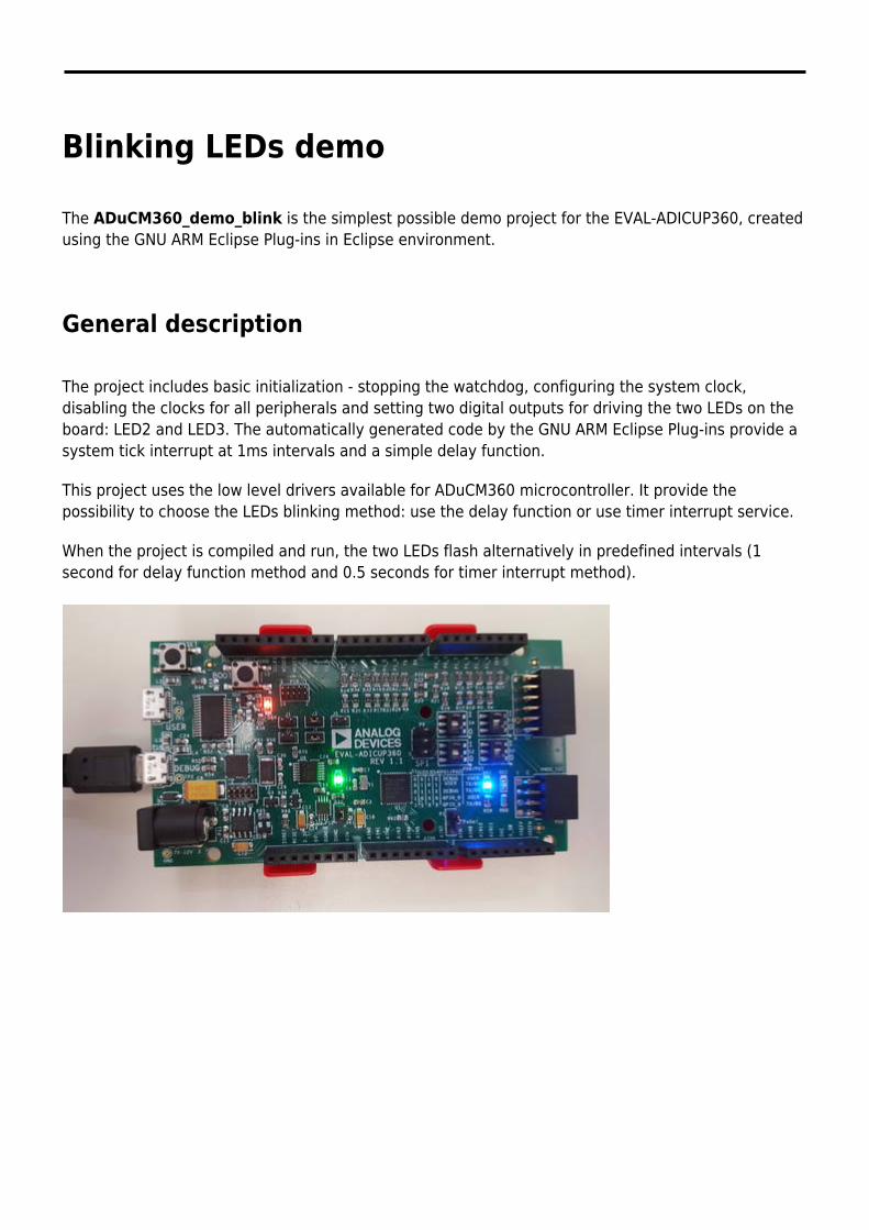
Blinking LEDs demo
The ADuCM360_demo_blink is the simplest possible demo project for the EVAL-ADICUP360, createdusing the GNU ARM Eclipse Plug-ins in Eclipse environment.
General description
The project includes basic initialization - stopping the watchdog, configuring the system clock,disabling the clocks for all peripherals and setting two digital outputs for driving the two LEDs on theboard: LED2 and LED3. The automatically generated code by the GNU ARM Eclipse Plug-ins provide asystem tick interrupt at 1ms intervals and a simple delay function.
This project uses the low level drivers available for ADuCM360 microcontroller. It provide thepossibility to choose the LEDs blinking method: use the delay function or use timer interrupt service.
When the project is compiled and run, the two LEDs flash alternatively in predefined intervals (1second for delay function method and 0.5 seconds for timer interrupt method).
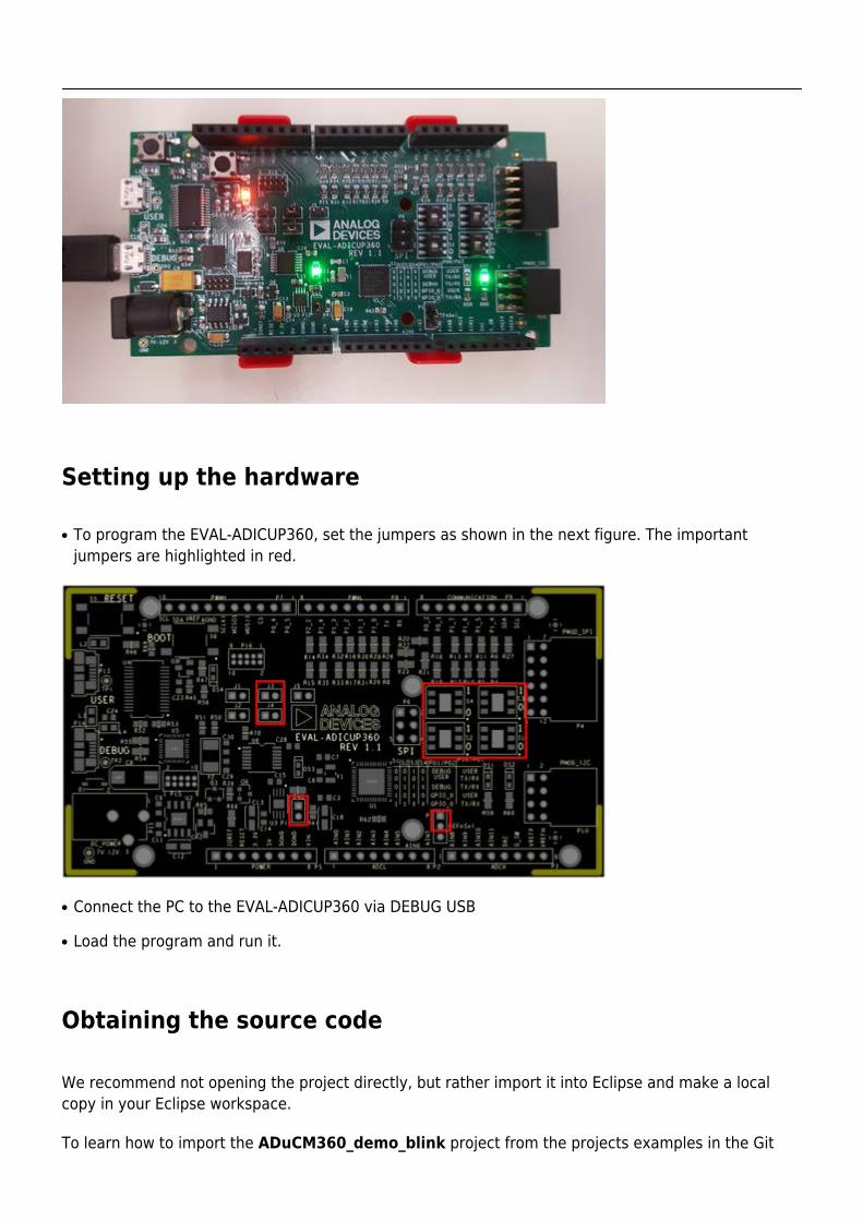
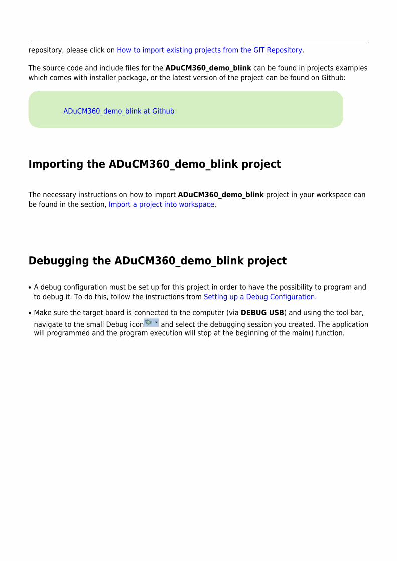
Setting up the hardware
To program the EVAL-ADICUP360, set the jumpers as shown in the next figure. The important●
jumpers are highlighted in red.
Connect the PC to the EVAL-ADICUP360 via DEBUG USB●
Load the program and run it.●
Obtaining the source code
We recommend not opening the project directly, but rather import it into Eclipse and make a localcopy in your Eclipse workspace.
To learn how to import the ADuCM360_demo_blink project from the projects examples in the Git
repository, please click on How to import existing projects from the GIT Repository.
The source code and include files for the ADuCM360_demo_blink can be found in projects exampleswhich comes with installer package, or the latest version of the project can be found on Github:
ADuCM360_demo_blink at Github
Importing the ADuCM360_demo_blink project
The necessary instructions on how to import ADuCM360_demo_blink project in your workspace canbe found in the section, Import a project into workspace.
Debugging the ADuCM360_demo_blink project
A debug configuration must be set up for this project in order to have the possibility to program and●
to debug it. To do this, follow the instructions from Setting up a Debug Configuration.
Make sure the target board is connected to the computer (via DEBUG USB) and using the tool bar,●
navigate to the small Debug icon and select the debugging session you created. The applicationwill programmed and the program execution will stop at the beginning of the main() function.
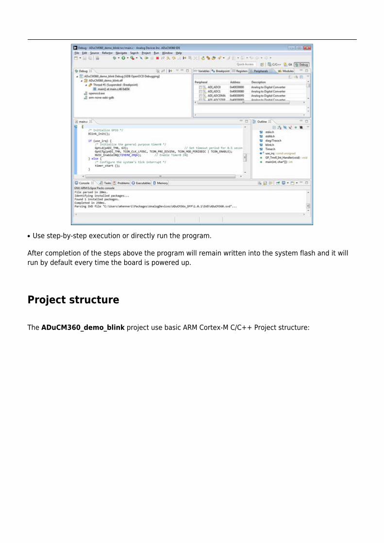
Use step-by-step execution or directly run the program.●
After completion of the steps above the program will remain written into the system flash and it willrun by default every time the board is powered up.
Project structure
The ADuCM360_demo_blink project use basic ARM Cortex-M C/C++ Project structure:
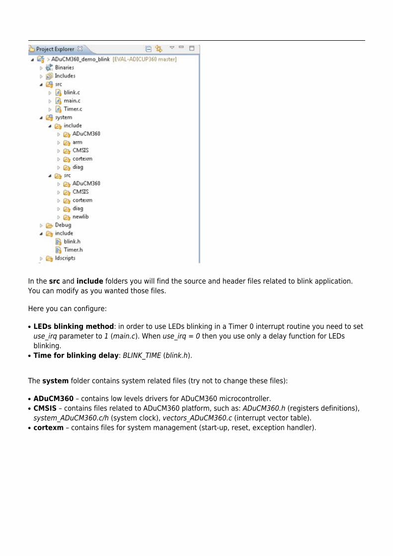
In the src and include folders you will find the source and header files related to blink application.You can modify as you wanted those files.
Here you can configure:
LEDs blinking method: in order to use LEDs blinking in a Timer 0 interrupt routine you need to set●
use_irq parameter to 1 (main.c). When use_irq = 0 then you use only a delay function for LEDsblinking.Time for blinking delay: BLINK_TIME (blink.h).●
The system folder contains system related files (try not to change these files):
ADuCM360 – contains low levels drivers for ADuCM360 microcontroller.●
CMSIS – contains files related to ADuCM360 platform, such as: ADuCM360.h (registers definitions),●
system_ADuCM360.c/h (system clock), vectors_ADuCM360.c (interrupt vector table).cortexm – contains files for system management (start-up, reset, exception handler).●
Command Line Interpreter Demo
The ADuCM360_demo_cli is a Command Line Interpreter (CLI) demo project for the EVAL-ADICUP360base board, created using the GNU ARM Eclipse Plug-ins in Eclipse environment.
General description
The purpose of this project is to help you to get used with UART peripheral of ADuCM360microcontroller. The source code example can serve as a template for a resident command lineinterpreter, complementing any other user application functionality. Interrupt-based receiving of textcommands from the UART is implemented. As soon as a command is entered, an execution requestflag is raised to signal the main loop. The commands are recognised and may be executedimmediately or later depending on the priority of the current tasks.
You can use any Terminal session you want, such as Putty or Serial Terminal with Eclipse Kepler(incorporated in Eclipse environment).
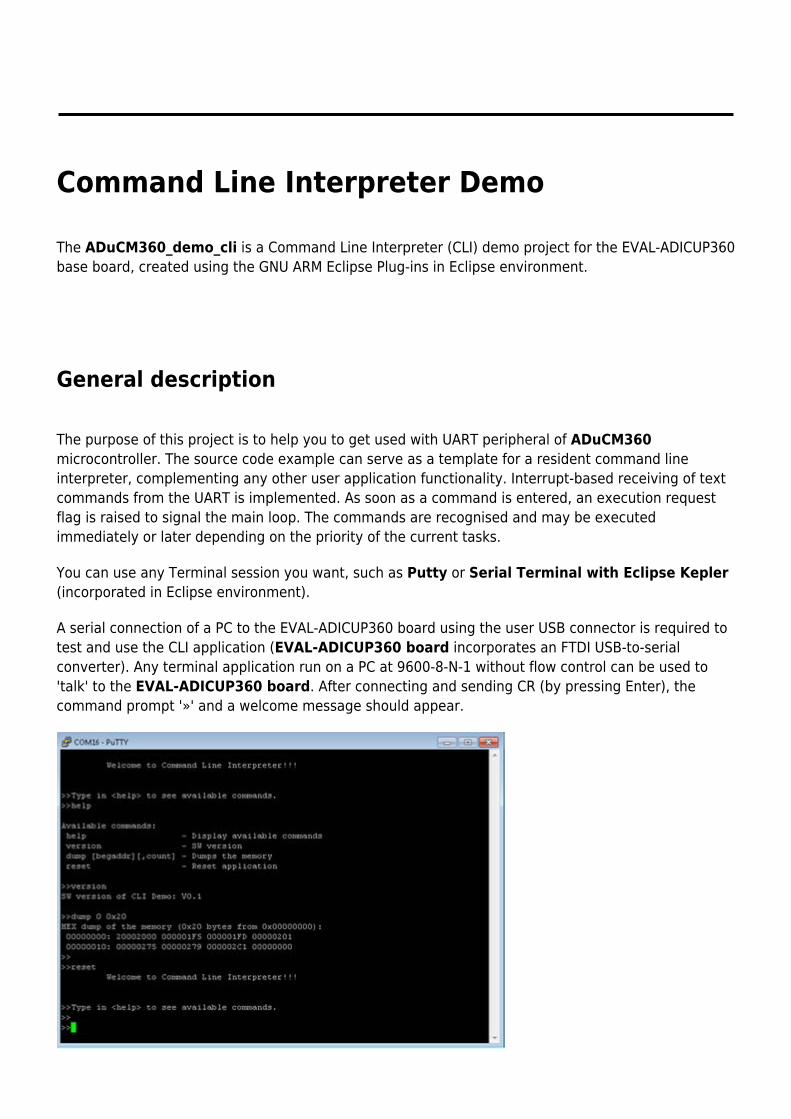
A serial connection of a PC to the EVAL-ADICUP360 board using the user USB connector is required totest and use the CLI application (EVAL-ADICUP360 board incorporates an FTDI USB-to-serialconverter). Any terminal application run on a PC at 9600-8-N-1 without flow control can be used to'talk' to the EVAL-ADICUP360 board. After connecting and sending CR (by pressing Enter), thecommand prompt '»' and a welcome message should appear.
Available commands
Command Descriptionhelp Display available commandsversion Display SW version of CLI project
dump [begaddr] [count]
Display up to 0x40 consecutive byte-sizelocations from any address of the ADuCM360 memory space.One should be careful not to request locations which are not decodedbecause the hardware_fault exception code will block the board.
reset Perform a HW reset which also initialize the application
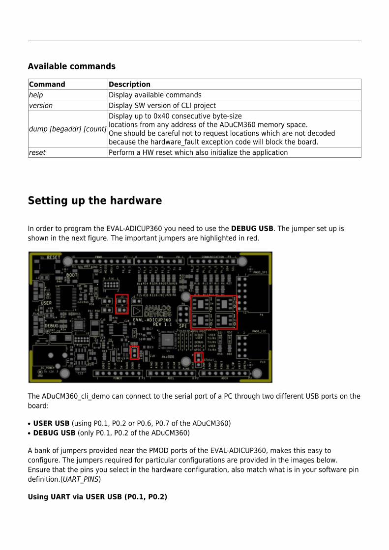
Setting up the hardware
In order to program the EVAL-ADICUP360 you need to use the DEBUG USB. The jumper set up isshown in the next figure. The important jumpers are highlighted in red.
The ADuCM360_cli_demo can connect to the serial port of a PC through two different USB ports on theboard:
USER USB (using P0.1, P0.2 or P0.6, P0.7 of the ADuCM360)●
DEBUG USB (only P0.1, P0.2 of the ADuCM360)●
A bank of jumpers provided near the PMOD ports of the EVAL-ADICUP360, makes this easy toconfigure. The jumpers required for particular configurations are provided in the images below.Ensure that the pins you select in the hardware configuration, also match what is in your software pindefinition.(UART_PINS)
Using UART via USER USB (P0.1, P0.2)
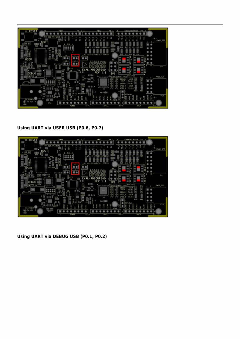
Using UART via USER USB (P0.6, P0.7)
Using UART via DEBUG USB (P0.1, P0.2)
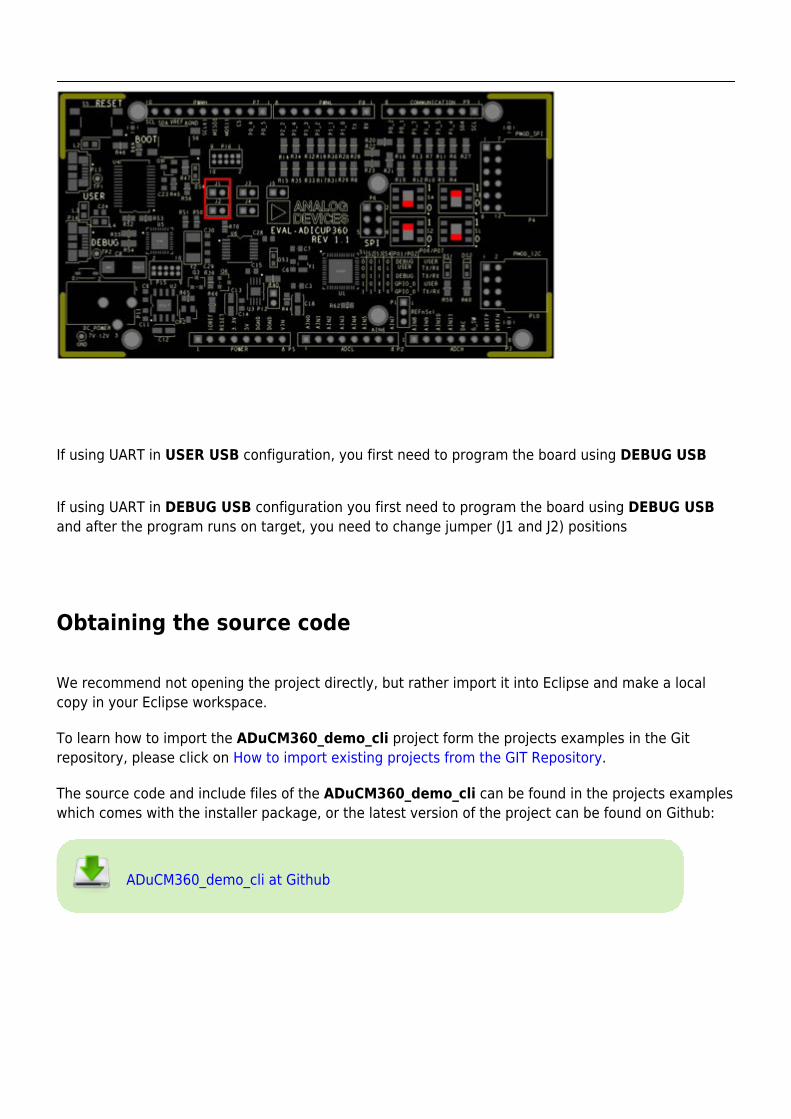
If using UART in USER USB configuration, you first need to program the board using DEBUG USB
If using UART in DEBUG USB configuration you first need to program the board using DEBUG USBand after the program runs on target, you need to change jumper (J1 and J2) positions
Obtaining the source code
We recommend not opening the project directly, but rather import it into Eclipse and make a localcopy in your Eclipse workspace.
To learn how to import the ADuCM360_demo_cli project form the projects examples in the Gitrepository, please click on How to import existing projects from the GIT Repository.
The source code and include files of the ADuCM360_demo_cli can be found in the projects exampleswhich comes with the installer package, or the latest version of the project can be found on Github:
ADuCM360_demo_cli at Github
Importing the ADuCM360_demo_cli project
The necessary instructions on how to import ADuCM360_demo_cli project in your workspace can befound in the section, Import a project into workspace.
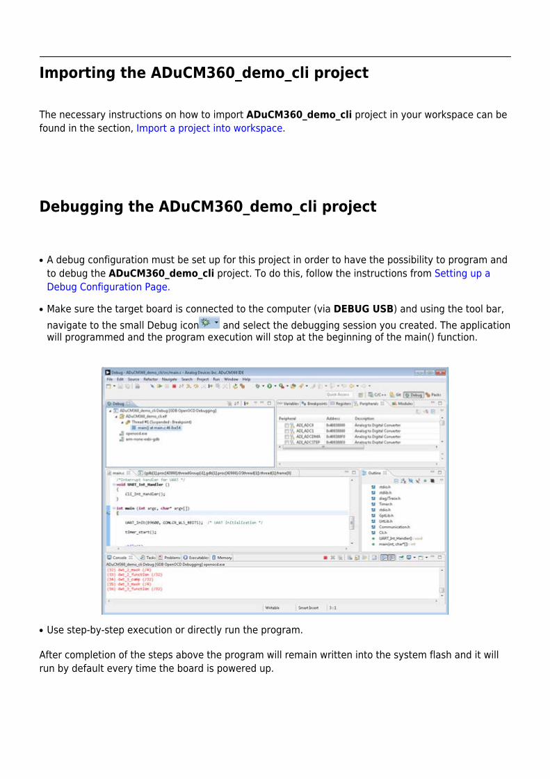
Debugging the ADuCM360_demo_cli project
A debug configuration must be set up for this project in order to have the possibility to program and●
to debug the ADuCM360_demo_cli project. To do this, follow the instructions from Setting up aDebug Configuration Page.
Make sure the target board is connected to the computer (via DEBUG USB) and using the tool bar,●
navigate to the small Debug icon and select the debugging session you created. The applicationwill programmed and the program execution will stop at the beginning of the main() function.
Use step-by-step execution or directly run the program.●
After completion of the steps above the program will remain written into the system flash and it willrun by default every time the board is powered up.
Project structure
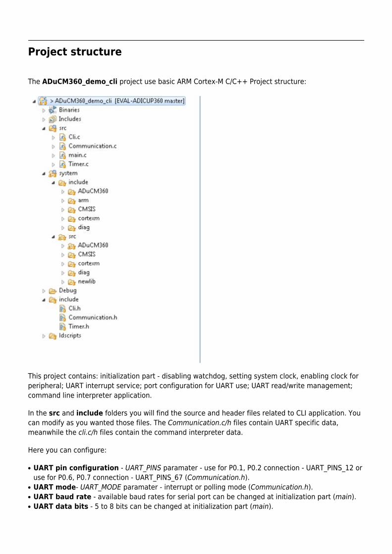
The ADuCM360_demo_cli project use basic ARM Cortex-M C/C++ Project structure:
This project contains: initialization part - disabling watchdog, setting system clock, enabling clock forperipheral; UART interrupt service; port configuration for UART use; UART read/write management;command line interpreter application.
In the src and include folders you will find the source and header files related to CLI application. Youcan modify as you wanted those files. The Communication.c/h files contain UART specific data,meanwhile the cli.c/h files contain the command interpreter data.
Here you can configure:
UART pin configuration - UART_PINS paramater - use for P0.1, P0.2 connection - UART_PINS_12 or●
use for P0.6, P0.7 connection - UART_PINS_67 (Communication.h).UART mode- UART_MODE paramater - interrupt or polling mode (Communication.h).●
UART baud rate - available baud rates for serial port can be changed at initialization part (main).●
UART data bits - 5 to 8 bits can be changed at initialization part (main).●
The system folder contains system related files (try not to change these files):
ADuCM360 – contains low levels drivers for ADuCM360 microcontroller.●
CMSIS – contains files related to ADuCM360 platform, such as: ADuCM360.h (registers definitions),●
system_ADuCM360.c/h (system clock), vectors_ADuCM360.c (interrupt vector table).cortexm – contains files for system management (start-up, reset, exception handler).●
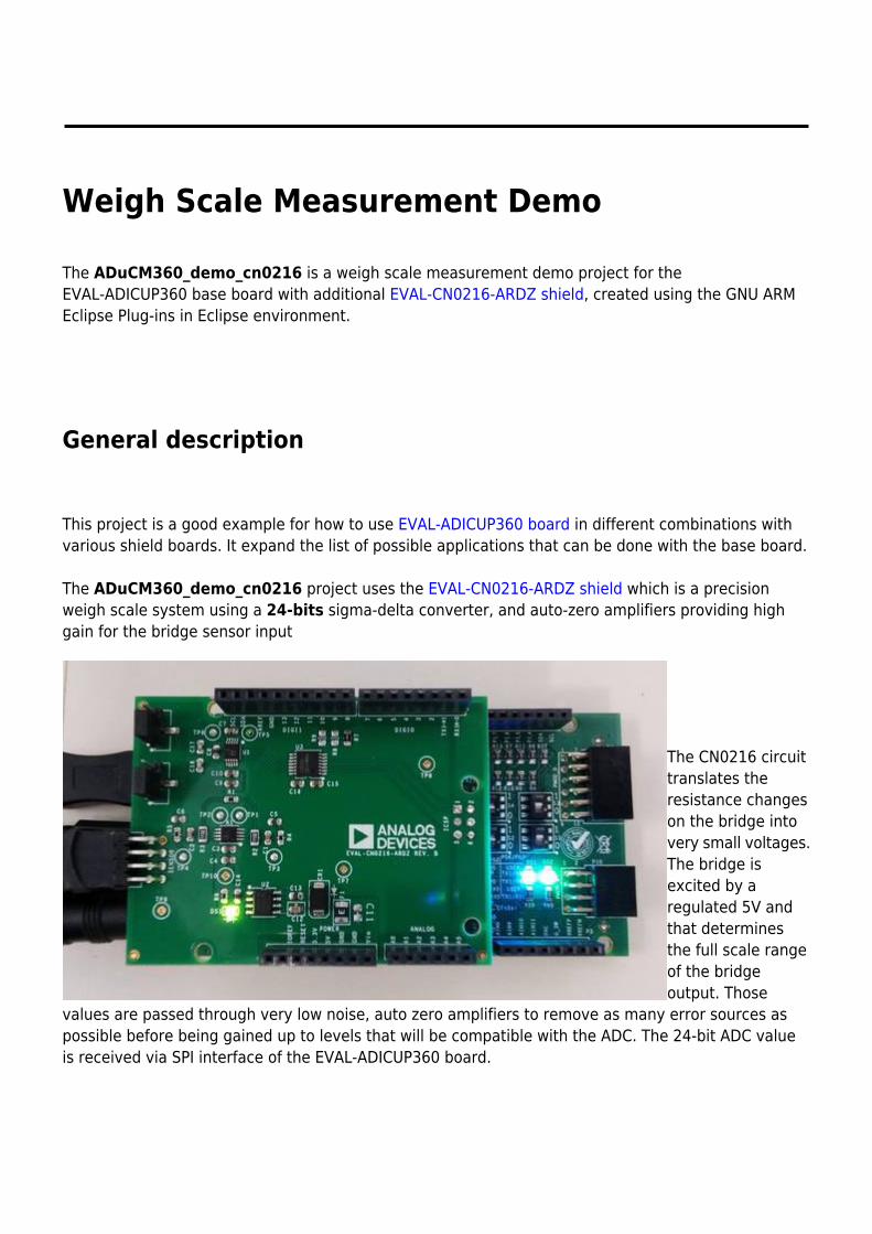
Weigh Scale Measurement Demo
The ADuCM360_demo_cn0216 is a weigh scale measurement demo project for theEVAL-ADICUP360 base board with additional EVAL-CN0216-ARDZ shield, created using the GNU ARMEclipse Plug-ins in Eclipse environment.
General description
This project is a good example for how to use EVAL-ADICUP360 board in different combinations withvarious shield boards. It expand the list of possible applications that can be done with the base board.
The ADuCM360_demo_cn0216 project uses the EVAL-CN0216-ARDZ shield which is a precisionweigh scale system using a 24-bits sigma-delta converter, and auto-zero amplifiers providing highgain for the bridge sensor input
The CN0216 circuittranslates theresistance changeson the bridge intovery small voltages.The bridge isexcited by aregulated 5V andthat determinesthe full scale rangeof the bridgeoutput. Those
values are passed through very low noise, auto zero amplifiers to remove as many error sources aspossible before being gained up to levels that will be compatible with the ADC. The 24-bit ADC valueis received via SPI interface of the EVAL-ADICUP360 board.
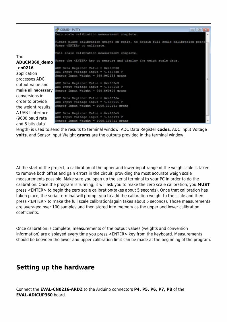
TheADuCM360_demo_cn0216applicationprocesses ADCoutput value andmake all necessaryconversions inorder to providethe weight results.A UART interface(9600 baud rateand 8-bits datalength) is used to send the results to terminal window: ADC Data Register codes, ADC Input Voltagevolts, and Sensor Input Weight grams are the outputs provided in the terminal window.
At the start of the project, a calibration of the upper and lower input range of the weigh scale is takento remove both offset and gain errors in the circuit, providing the most accurate weigh scalemeasurements possible. Make sure you open up the serial terminal to your PC in order to do thecalibration. Once the program is running, it will ask you to make the zero scale calibration, you MUSTpress <ENTER> to begin the zero scale calibration(takes about 5 seconds). Once that calibration hastaken place, the serial terminal will prompt you to add the calibration weight to the scale and thenpress <ENTER> to make the full scale calibration(again takes about 5 seconds). Those measurementsare averaged over 100 samples and then stored into memory as the upper and lower calibrationcoefficients.
Once calibration is complete, measurements of the output values (weights and conversioninformation) are displayed every time you press <ENTER> key from the keyboard. Measurementsshould be between the lower and upper calibration limit can be made at the beginning of the program.
Setting up the hardware
Connect the EVAL-CN0216-ARDZ to the Arduino connectors P4, P5, P6, P7, P8 of theEVAL-ADICUP360 board.
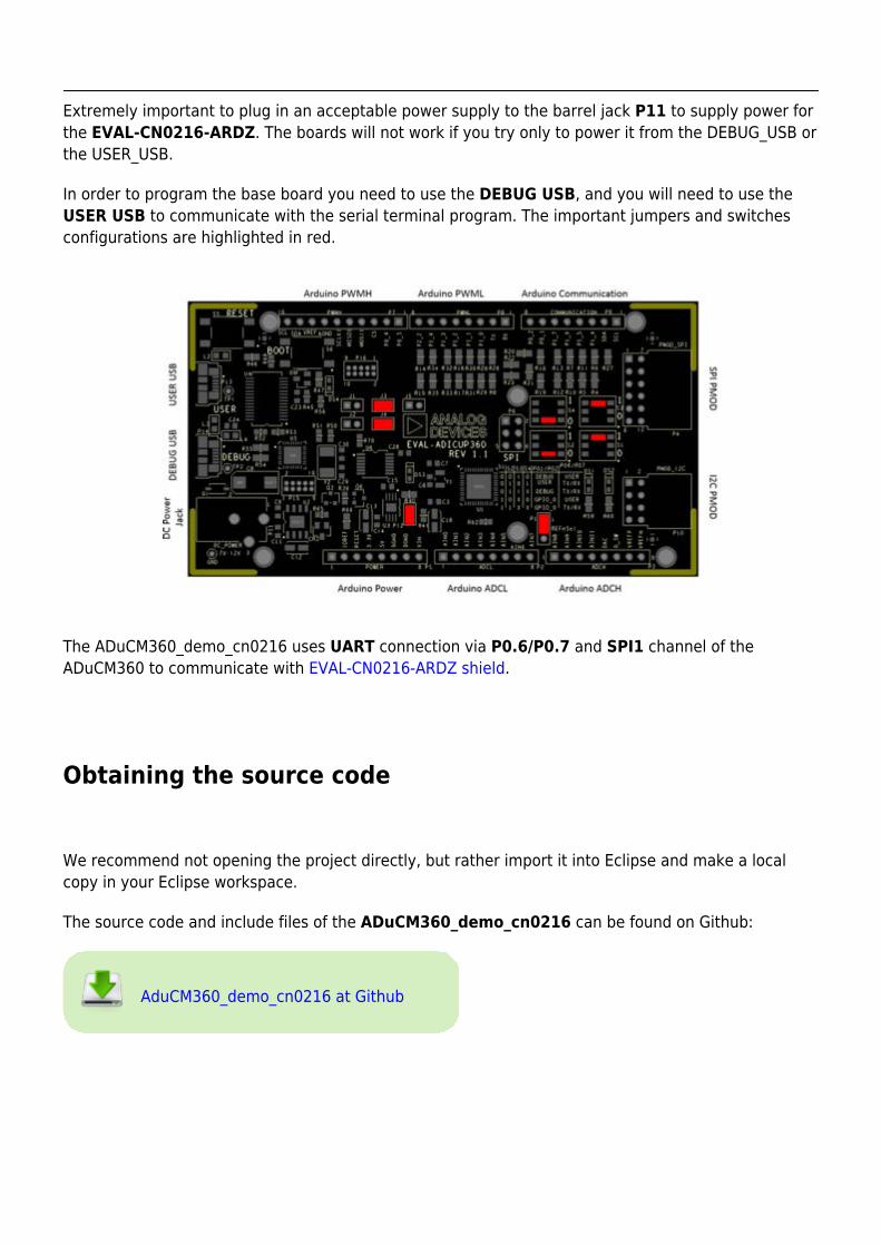
Extremely important to plug in an acceptable power supply to the barrel jack P11 to supply power forthe EVAL-CN0216-ARDZ. The boards will not work if you try only to power it from the DEBUG_USB orthe USER_USB.
In order to program the base board you need to use the DEBUG USB, and you will need to use theUSER USB to communicate with the serial terminal program. The important jumpers and switchesconfigurations are highlighted in red.
The ADuCM360_demo_cn0216 uses UART connection via P0.6/P0.7 and SPI1 channel of theADuCM360 to communicate with EVAL-CN0216-ARDZ shield.
Obtaining the source code
We recommend not opening the project directly, but rather import it into Eclipse and make a localcopy in your Eclipse workspace.
The source code and include files of the ADuCM360_demo_cn0216 can be found on Github:
AduCM360_demo_cn0216 at Github
Importing the ADuCM360_demo_cn0216 project
The necessary instructions on how to import the ADuCM360_demo_cn0216 project form theprojects examples in the Git repository, can be found in How to import existing projects from the GITRepository page.
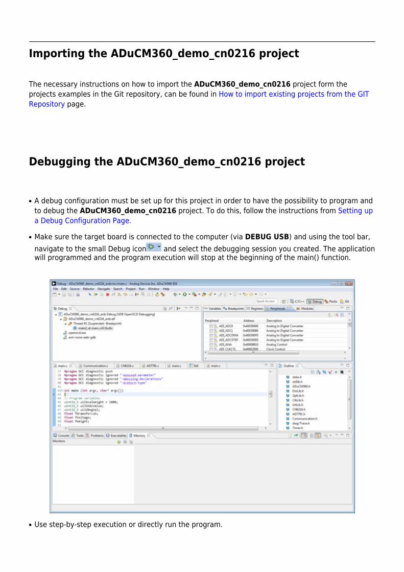
Debugging the ADuCM360_demo_cn0216 project
A debug configuration must be set up for this project in order to have the possibility to program and●
to debug the ADuCM360_demo_cn0216 project. To do this, follow the instructions from Setting upa Debug Configuration Page.
Make sure the target board is connected to the computer (via DEBUG USB) and using the tool bar,●
navigate to the small Debug icon and select the debugging session you created. The applicationwill programmed and the program execution will stop at the beginning of the main() function.
Use step-by-step execution or directly run the program.●
After completion of the steps above the program will remain written into the system flash and it willrun by default every time the board is powered up.
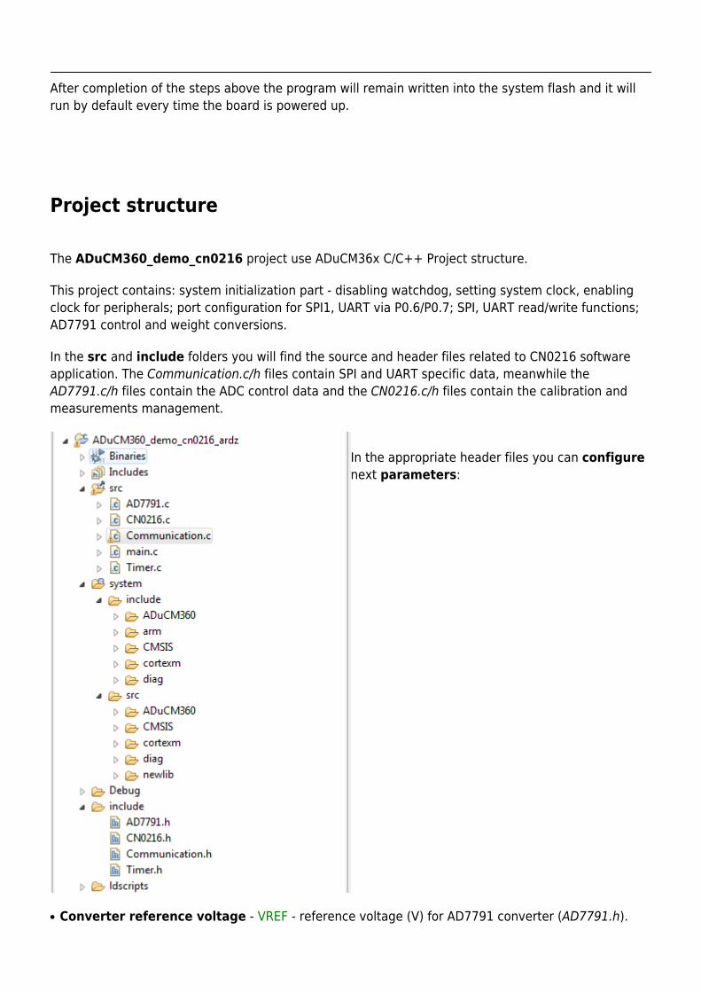
Project structure
The ADuCM360_demo_cn0216 project use ADuCM36x C/C++ Project structure.
This project contains: system initialization part - disabling watchdog, setting system clock, enablingclock for peripherals; port configuration for SPI1, UART via P0.6/P0.7; SPI, UART read/write functions;AD7791 control and weight conversions.
In the src and include folders you will find the source and header files related to CN0216 softwareapplication. The Communication.c/h files contain SPI and UART specific data, meanwhile theAD7791.c/h files contain the ADC control data and the CN0216.c/h files contain the calibration andmeasurements management.
In the appropriate header files you can configurenext parameters:
Converter reference voltage - VREF - reference voltage (V) for AD7791 converter (AD7791.h).●
#define VREF 5
Full scale calibration weight - CAL_WEIGHT - this parameter can be set to the numeric value of●
the full scale calibration weight you are using. (in grams) (CN0216.h).
#define CAL_WEIGHT 1000
The system folder contains system related files (try not to change these files):
ADuCM360 – contains low levels drivers for ADuCM360 microcontroller.●
CMSIS – contains files related to ADuCM360 platform, such as: ADuCM360.h (registers definitions),●
system_ADuCM360.c/h (system clock), vectors_ADuCM360.c (interrupt vector table).cortexm – contains files for system management (start-up, reset, exception handler).●
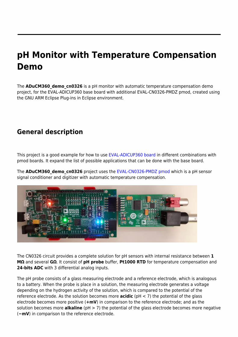
pH Monitor with Temperature CompensationDemo
The ADuCM360_demo_cn0326 is a pH monitor with automatic temperature compensation demoproject, for the EVAL-ADICUP360 base board with additional EVAL-CN0326-PMDZ pmod, created usingthe GNU ARM Eclipse Plug-ins in Eclipse environment.
General description
This project is a good example for how to use EVAL-ADICUP360 board in different combinations withpmod boards. It expand the list of possible applications that can be done with the base board.
The ADuCM360_demo_cn0326 project uses the EVAL-CN0326-PMDZ pmod which is a pH sensorsignal conditioner and digitizer with automatic temperature compensation.
The CN0326 circuit provides a complete solution for pH sensors with internal resistance between 1MΩ and several GΩ. It consist of pH probe buffer, Pt1000 RTD for temperature compensation and24-bits ADC with 3 differential analog inputs.
The pH probe consists of a glass measuring electrode and a reference electrode, which is analogousto a battery. When the probe is place in a solution, the measuring electrode generates a voltagedepending on the hydrogen activity of the solution, which is compared to the potential of thereference electrode. As the solution becomes more acidic (pH < 7) the potential of the glasselectrode becomes more positive (+mV) in comparison to the reference electrode; and as thesolution becomes more alkaline (pH > 7) the potential of the glass electrode becomes more negative(−mV) in comparison to the reference electrode.
The change in temperature of the solution changes the activity of its hydrogen ions. When thesolution is heated, the hydrogen ions move faster which result in an increase in potential differenceacross the two electrodes. In addition, when the solution is cooled, the hydrogen activity decreasescausing a decrease in the potential difference. Electrodes are designed ideally to produce a zero volt (0 V) potential when placed in a buffer solution with a pH of 7 (neutral pH).
The EVAL-CN0326-PMDZ comes with an evaluation software which can help you to test and tocalibrate your pmod before you use it.
Please visit CN0326 Software User Guide page to find out how to get and how to use the CN0326evaluation software.
The potential changes are outputted as ADC 24-bits value which is received via SPI interface of theEVAL-ADICUP360 board. The ADC analog differential channels are:
AIN1(+)/AIN1(-) - pH probe (voltage full range: ±414 mV at 25°C to ±490 mV at 80°C)●
AIN2(+)/AIN2(-) - Pt1000 RTD (voltage full range: 210 mV to 290 mV with 210 μA excitation●
current)AIN3(+)/AIN3(-) - Bias current (used to minimized tne voltage errors)●
The ADuCM360_demo_cn0326 application purchase ADC outputs from input channels, calculatesvoltage, temperature and pH values. You can choose to use internal excitation current of the ADC(IOUT2) or calculate bias current of the circuit (see USE_IOUT2 parameter).
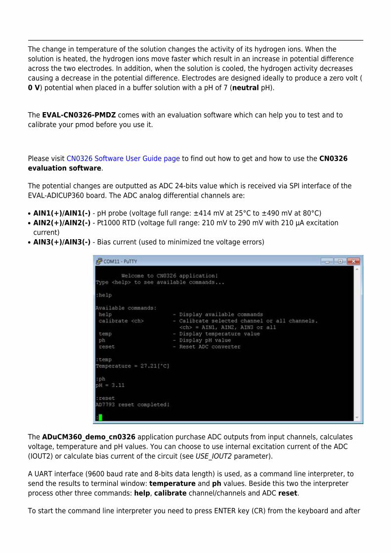
A UART interface (9600 baud rate and 8-bits data length) is used, as a command line interpreter, tosend the results to terminal window: temperature and ph values. Beside this two the interpreterprocess other three commands: help, calibrate channel/channels and ADC reset.
To start the command line interpreter you need to press ENTER key (CR) from the keyboard and after
that just type in <help> to see available commands. The output data are send via UART usingsemihosting mechanism.
The project uses below formula to determine output ADC code for an input voltage on either channel:
AIN - analog input voltageGAIN - gain value in the in-amp settingN - ADC resolution (24)
The temperature value is calculated using RTD resistance value and it varies from 0°C (1000 Ω) to100°C (1385 Ω):
Rrtd - RTD resistance at T°CRmin - RTD resistance at 0°Cα - temperature coefficient (0.00385 Ω/Ω/°C)
To calculate pH value is used Nernst equation:
E - voltage of the hydrogen electrode withunknown activityα - zero point tolerance (±30 mV)T - ambient temperature in °Cn - valence, number of charges on ion (1 at 25°C)F - Faraday constant (96485 coulombs/mol)R - Avogadro's number (8314 mV-coulombs /°K
mol)pHiso - reference hydrogen ion concentration (7)
Semihosting with ARM
Semihosting is a mechanism that connect the target firmware's standard IO (printf, scanf/fgets, open,write, read, close, etc) to your host PC via JTAG or SWD. It’s easy to configure it with open sourcetooling - the newlib C standard library and OpenOCD JTAG implementation.
You can automatic enable semihosting and configure it by using the project ADuCM36x C/C+ +Project template, which offer you the ability to select how do you want to use semihosting.
This example present the possibility to use semihosting to output messages with printf() by using aphysical serial connection as UART. It uses the newlib GNU ARM library which actually links the UARTphysical port to standard C functions. You need only to overwrite _write() function, which is markedas weak function in the GNU ARM library, with your own function that write characters to UART (thesame for _read() function when you want to use scanf() in your code).
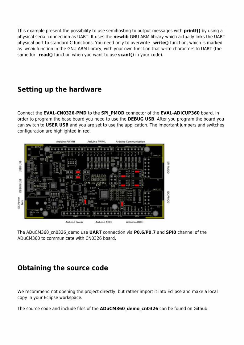
Setting up the hardware
Connect the EVAL-CN0326-PMD to the SPI_PMOD connector of the EVAL-ADICUP360 board. Inorder to program the base board you need to use the DEBUG USB. After you program the board youcan switch to USER USB and you are set to use the application. The important jumpers and switchesconfiguration are highlighted in red.
The ADuCM360_cn0326_demo use UART connection via P0.6/P0.7 and SPI0 channel of theADuCM360 to communicate with CN0326 board.
Obtaining the source code
We recommend not opening the project directly, but rather import it into Eclipse and make a localcopy in your Eclipse workspace.
The source code and include files of the ADuCM360_demo_cn0326 can be found on Github:
AduCM360_demo_cn0326 at Github
Importing the ADuCM360_demo_cn0326 project
The necessary instructions on how to import the ADuCM360_demo_cn0326 project form theprojects examples in the Git repository, can be found in How to import existing projects from the GITRepository page.
Debugging the ADuCM360_demo_cn0326 project
A debug configuration must be set up for this project in order to have the possibility to program and●
to debug the ADuCM360_demo_cn0326 project. To do this, follow the instructions from Setting upa Debug Configuration Page.
Make sure the target board is connected to the computer (via DEBUG USB) and using the tool bar,●
navigate to the small Debug icon and select the debugging session you created. The applicationwill programmed and the program execution will stop at the beginning of the main() function.
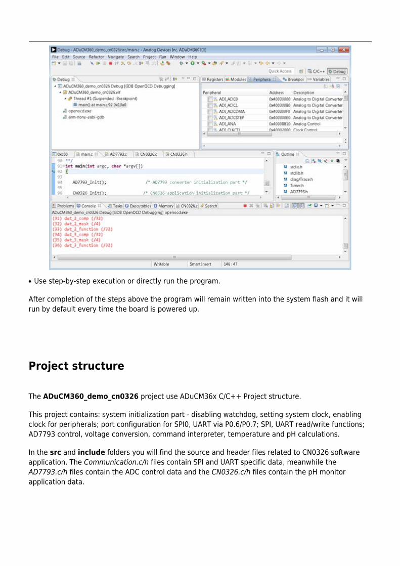
Use step-by-step execution or directly run the program.●
After completion of the steps above the program will remain written into the system flash and it willrun by default every time the board is powered up.
Project structure
The ADuCM360_demo_cn0326 project use ADuCM36x C/C++ Project structure.
This project contains: system initialization part - disabling watchdog, setting system clock, enablingclock for peripherals; port configuration for SPI0, UART via P0.6/P0.7; SPI, UART read/write functions;AD7793 control, voltage conversion, command interpreter, temperature and pH calculations.
In the src and include folders you will find the source and header files related to CN0326 softwareapplication. The Communication.c/h files contain SPI and UART specific data, meanwhile theAD7793.c/h files contain the ADC control data and the CN0326.c/h files contain the pH monitorapplication data.
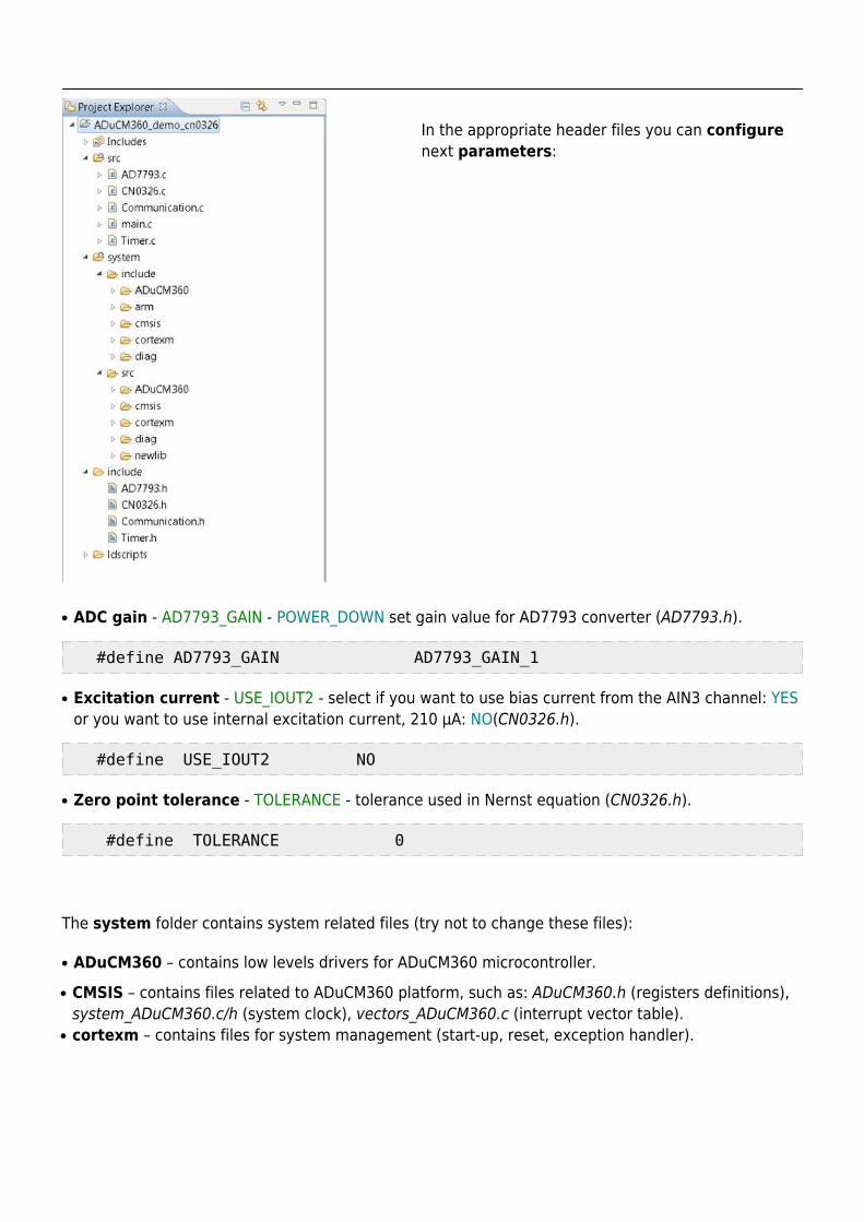
In the appropriate header files you can configurenext parameters:
ADC gain - AD7793_GAIN - POWER_DOWN set gain value for AD7793 converter (AD7793.h).●
#define AD7793_GAIN AD7793_GAIN_1
Excitation current - USE_IOUT2 - select if you want to use bias current from the AIN3 channel: YES●
or you want to use internal excitation current, 210 µA: NO(CN0326.h).
#define USE_IOUT2 NO
Zero point tolerance - TOLERANCE - tolerance used in Nernst equation (CN0326.h).●
#define TOLERANCE 0
The system folder contains system related files (try not to change these files):
ADuCM360 – contains low levels drivers for ADuCM360 microcontroller.●
CMSIS – contains files related to ADuCM360 platform, such as: ADuCM360.h (registers definitions),●
system_ADuCM360.c/h (system clock), vectors_ADuCM360.c (interrupt vector table).cortexm – contains files for system management (start-up, reset, exception handler).●
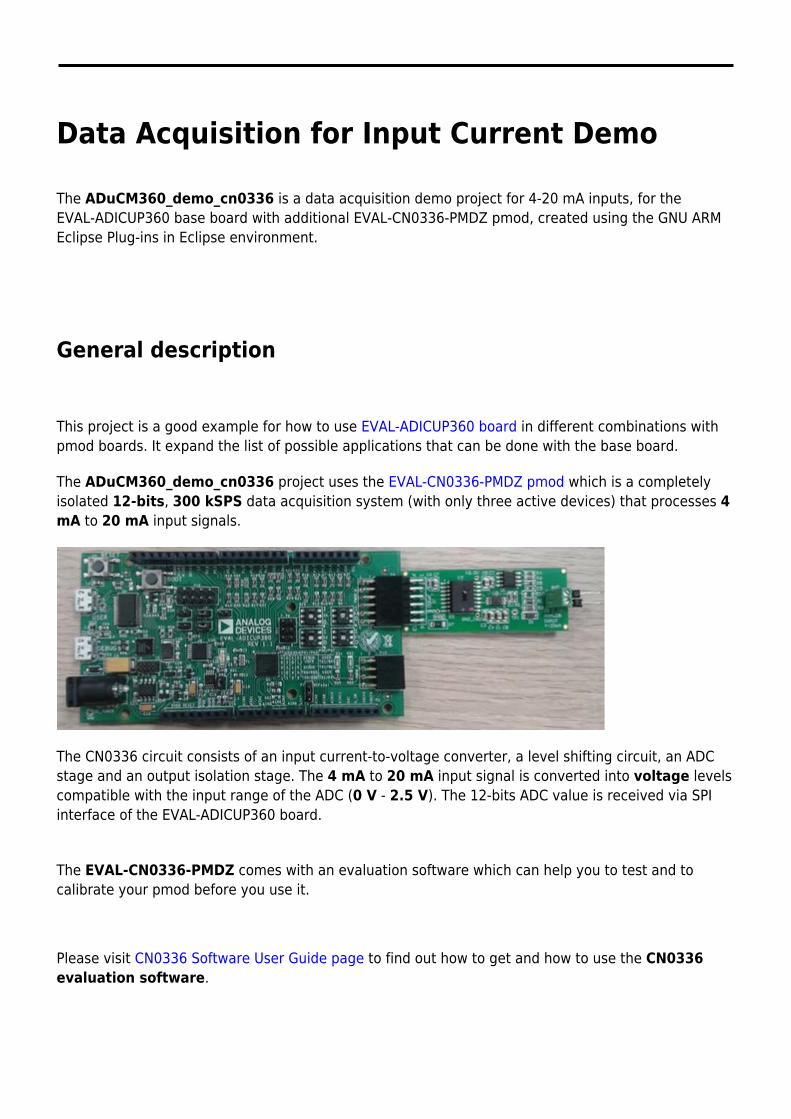
Data Acquisition for Input Current Demo
The ADuCM360_demo_cn0336 is a data acquisition demo project for 4-20 mA inputs, for theEVAL-ADICUP360 base board with additional EVAL-CN0336-PMDZ pmod, created using the GNU ARMEclipse Plug-ins in Eclipse environment.
General description
This project is a good example for how to use EVAL-ADICUP360 board in different combinations withpmod boards. It expand the list of possible applications that can be done with the base board.
The ADuCM360_demo_cn0336 project uses the EVAL-CN0336-PMDZ pmod which is a completelyisolated 12-bits, 300 kSPS data acquisition system (with only three active devices) that processes 4mA to 20 mA input signals.
The CN0336 circuit consists of an input current-to-voltage converter, a level shifting circuit, an ADCstage and an output isolation stage. The 4 mA to 20 mA input signal is converted into voltage levelscompatible with the input range of the ADC (0 V - 2.5 V). The 12-bits ADC value is received via SPIinterface of the EVAL-ADICUP360 board.
The EVAL-CN0336-PMDZ comes with an evaluation software which can help you to test and tocalibrate your pmod before you use it.
Please visit CN0336 Software User Guide page to find out how to get and how to use the CN0336evaluation software.
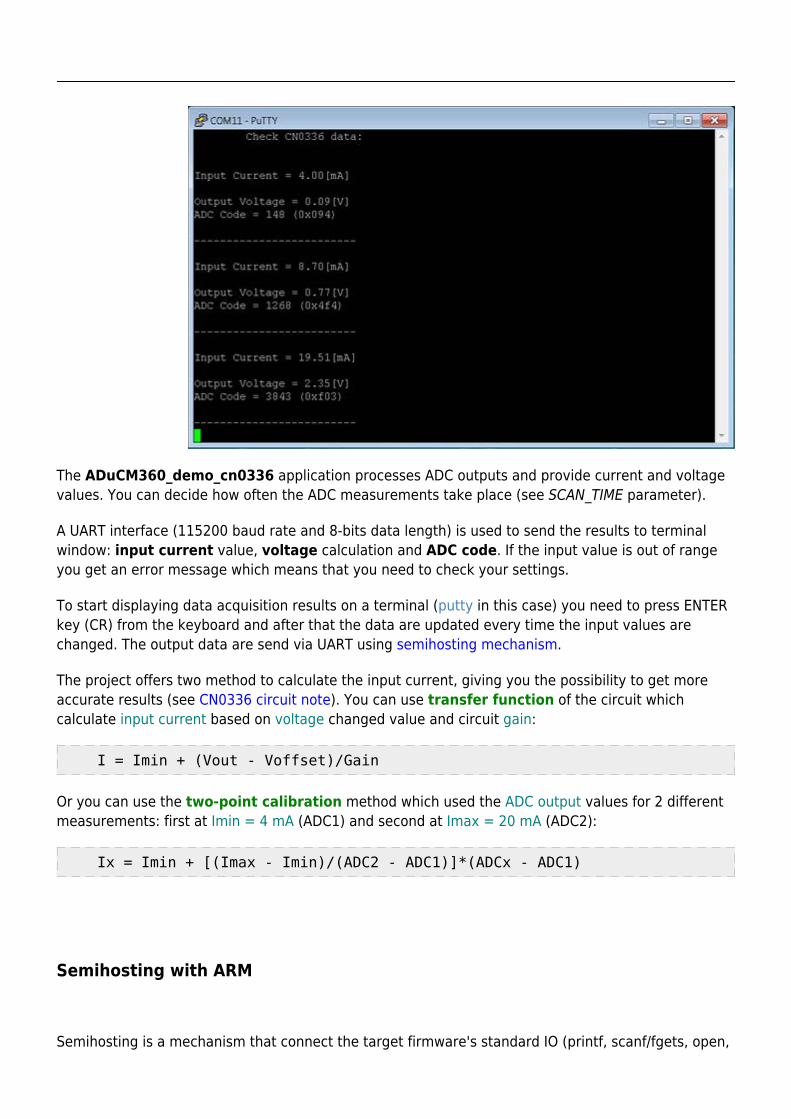
The ADuCM360_demo_cn0336 application processes ADC outputs and provide current and voltagevalues. You can decide how often the ADC measurements take place (see SCAN_TIME parameter).
A UART interface (115200 baud rate and 8-bits data length) is used to send the results to terminalwindow: input current value, voltage calculation and ADC code. If the input value is out of rangeyou get an error message which means that you need to check your settings.
To start displaying data acquisition results on a terminal (putty in this case) you need to press ENTERkey (CR) from the keyboard and after that the data are updated every time the input values arechanged. The output data are send via UART using semihosting mechanism.
The project offers two method to calculate the input current, giving you the possibility to get moreaccurate results (see CN0336 circuit note). You can use transfer function of the circuit whichcalculate input current based on voltage changed value and circuit gain:
I = Imin + (Vout - Voffset)/Gain
Or you can use the two-point calibration method which used the ADC output values for 2 differentmeasurements: first at Imin = 4 mA (ADC1) and second at Imax = 20 mA (ADC2):
Ix = Imin + [(Imax - Imin)/(ADC2 - ADC1)]*(ADCx - ADC1)
Semihosting with ARM
Semihosting is a mechanism that connect the target firmware's standard IO (printf, scanf/fgets, open,
write, read, close, etc) to your host PC via JTAG or SWD. It’s easy to configure it with open sourcetooling - the newlib C standard library and OpenOCD JTAG implementation.
You can automatic enable semihosting and configure it by using the project ADuCM36x C/C+ +Project template, which offer you the ability to select how do you want to use semihosting.
This example present the possibility to use semihosting to output messages with printf() by using aphysical serial connection as UART. It uses the newlib GNU ARM library which actually links the UARTphysical port to standard C functions. You need only to overwrite _write() function, which is markedas weak function in the GNU ARM library, with your own function that write characters to UART (thesame for _read() function when you want to use scanf() in your code).
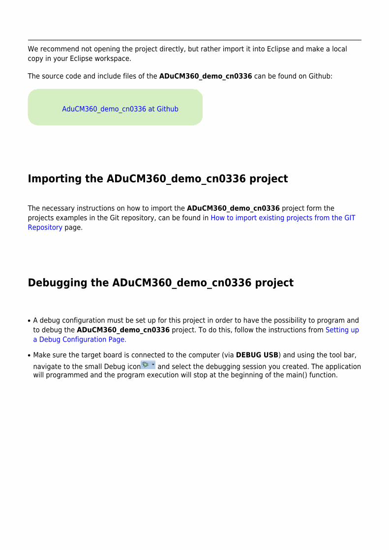
Setting up the hardware
Connect the EVAL-CN0336-PMD to the SPI_PMOD connector of the EVAL-ADICUP360 board. Inorder to program the base board you need to use the DEBUG USB. After you program the board youcan switch to USER USB and you are set to use the application. The important jumpers and switchesconfiguration are highlighted in red.
The ADuCM360_cn0336_demo use UART connection via P0.6/P0.7 and SPI0 channel of theADuCM360 to communicate with CN0336 board.
Obtaining the source code
We recommend not opening the project directly, but rather import it into Eclipse and make a localcopy in your Eclipse workspace.
The source code and include files of the ADuCM360_demo_cn0336 can be found on Github:
AduCM360_demo_cn0336 at Github
Importing the ADuCM360_demo_cn0336 project
The necessary instructions on how to import the ADuCM360_demo_cn0336 project form theprojects examples in the Git repository, can be found in How to import existing projects from the GITRepository page.
Debugging the ADuCM360_demo_cn0336 project
A debug configuration must be set up for this project in order to have the possibility to program and●
to debug the ADuCM360_demo_cn0336 project. To do this, follow the instructions from Setting upa Debug Configuration Page.
Make sure the target board is connected to the computer (via DEBUG USB) and using the tool bar,●
navigate to the small Debug icon and select the debugging session you created. The applicationwill programmed and the program execution will stop at the beginning of the main() function.
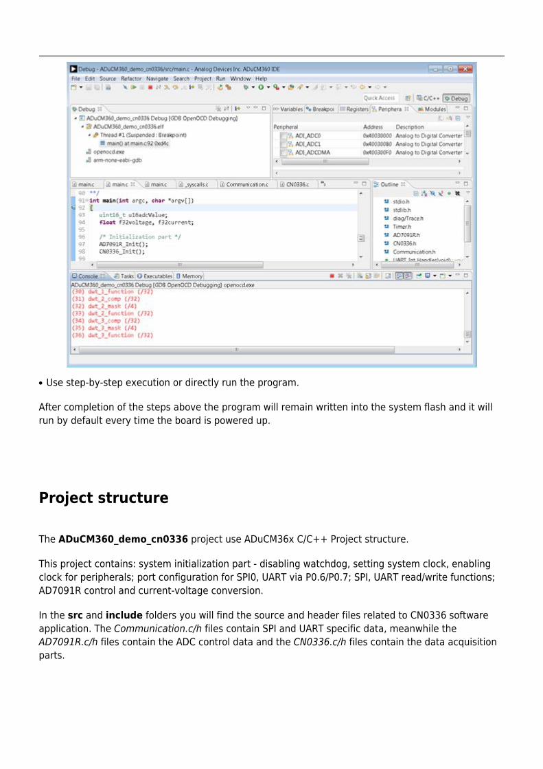
Use step-by-step execution or directly run the program.●
After completion of the steps above the program will remain written into the system flash and it willrun by default every time the board is powered up.
Project structure
The ADuCM360_demo_cn0336 project use ADuCM36x C/C++ Project structure.
This project contains: system initialization part - disabling watchdog, setting system clock, enablingclock for peripherals; port configuration for SPI0, UART via P0.6/P0.7; SPI, UART read/write functions;AD7091R control and current-voltage conversion.
In the src and include folders you will find the source and header files related to CN0336 softwareapplication. The Communication.c/h files contain SPI and UART specific data, meanwhile theAD7091R.c/h files contain the ADC control data and the CN0336.c/h files contain the data acquisitionparts.
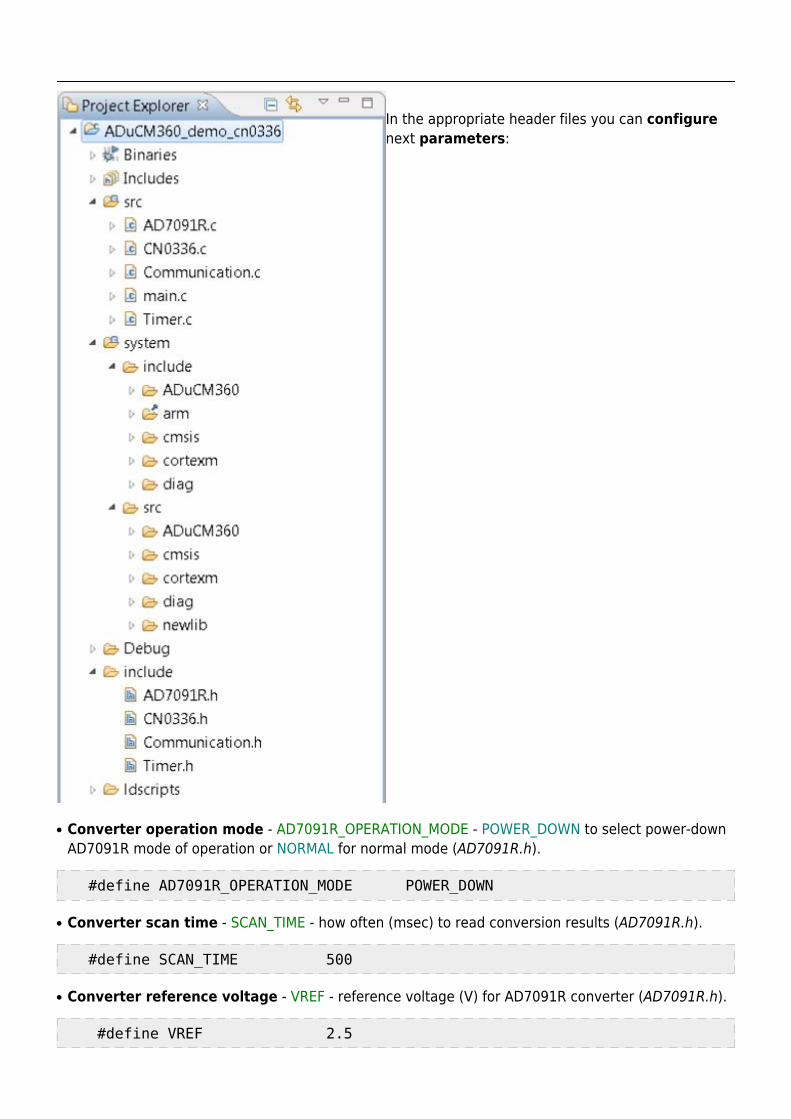
In the appropriate header files you can configurenext parameters:
Converter operation mode - AD7091R_OPERATION_MODE - POWER_DOWN to select power-down●
AD7091R mode of operation or NORMAL for normal mode (AD7091R.h).
#define AD7091R_OPERATION_MODE POWER_DOWN
Converter scan time - SCAN_TIME - how often (msec) to read conversion results (AD7091R.h).●
#define SCAN_TIME 500
Converter reference voltage - VREF - reference voltage (V) for AD7091R converter (AD7091R.h).●
#define VREF 2.5
Current calculation formula - CALC_FORMULA - this parameter can be set as●
TRANSFER_FUNCTION or TWO_POINT_CALIBRATION (CN0336.h).
#define CALC_FORMULA TWO_POINT_CALIBRATION
Data acquisition parameters - all needed parameters for data calculations (CN0336.h).●
#define IMIN 4 /* Imin [mA] */ #define IMAX 20 /* Imax [mA] */ #define ADC_MIN 147 /* ADC min for IMIN */ #define ADC_MAX 3960 /* ADC max for IMAX */
The system folder contains system related files (try not to change these files):
ADuCM360 – contains low levels drivers for ADuCM360 microcontroller.●
CMSIS – contains files related to ADuCM360 platform, such as: ADuCM360.h (registers definitions),●
system_ADuCM360.c/h (system clock), vectors_ADuCM360.c (interrupt vector table).cortexm – contains files for system management (start-up, reset, exception handler).●
Test procedure
The ADuCM360_demo_cn0336 project was tested using the base HW configuration(EVAL-ADICUP360 board together with EVAL-CN0336-PMDZ pmod) and by using additionalEVAL-CN0179-PMDZ pmod which was choose because it can generate the input current betweenrequired range 4mA - 20 mA.
In order to generate input current with CN0179 circuit is necessary just to use ADI availableevaluation software for this pmod (CN-0179 Software User Guide).
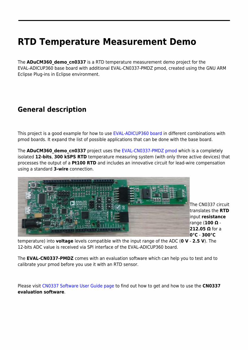
RTD Temperature Measurement Demo
The ADuCM360_demo_cn0337 is a RTD temperature measurement demo project for theEVAL-ADICUP360 base board with additional EVAL-CN0337-PMDZ pmod, created using the GNU ARMEclipse Plug-ins in Eclipse environment.
General description
This project is a good example for how to use EVAL-ADICUP360 board in different combinations withpmod boards. It expand the list of possible applications that can be done with the base board.
The ADuCM360_demo_cn0337 project uses the EVAL-CN0337-PMDZ pmod which is a completelyisolated 12-bits, 300 kSPS RTD temperature measuring system (with only three active devices) thatprocesses the output of a Pt100 RTD and includes an innovative circuit for lead-wire compensationusing a standard 3-wire connection.
The CN0337 circuittranslates the RTDinput resistancerange (100 Ω -212.05 Ω for a0°C - 300°C
temperature) into voltage levels compatible with the input range of the ADC (0 V - 2.5 V). The12-bits ADC value is received via SPI interface of the EVAL-ADICUP360 board.
The EVAL-CN0337-PMDZ comes with an evaluation software which can help you to test and tocalibrate your pmod before you use it with an RTD sensor.
Please visit CN0337 Software User Guide page to find out how to get and how to use the CN0337evaluation software.
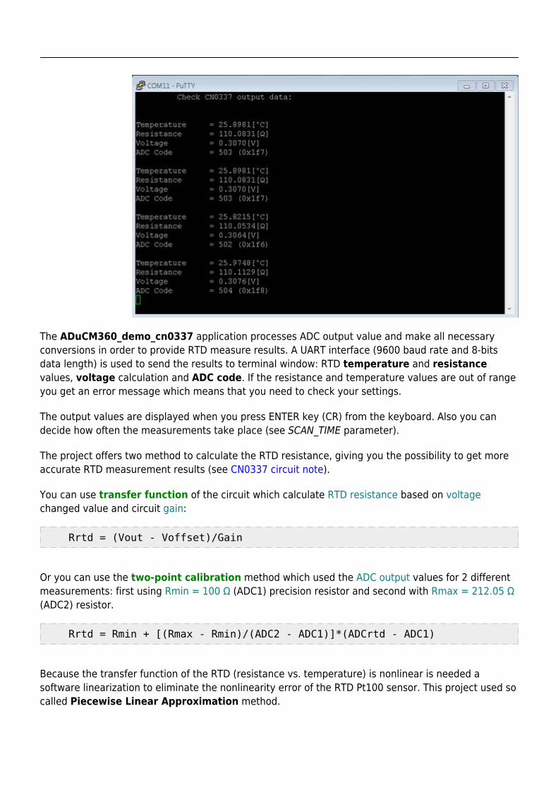
The ADuCM360_demo_cn0337 application processes ADC output value and make all necessaryconversions in order to provide RTD measure results. A UART interface (9600 baud rate and 8-bitsdata length) is used to send the results to terminal window: RTD temperature and resistancevalues, voltage calculation and ADC code. If the resistance and temperature values are out of rangeyou get an error message which means that you need to check your settings.
The output values are displayed when you press ENTER key (CR) from the keyboard. Also you candecide how often the measurements take place (see SCAN_TIME parameter).
The project offers two method to calculate the RTD resistance, giving you the possibility to get moreaccurate RTD measurement results (see CN0337 circuit note).
You can use transfer function of the circuit which calculate RTD resistance based on voltagechanged value and circuit gain:
Rrtd = (Vout - Voffset)/Gain
Or you can use the two-point calibration method which used the ADC output values for 2 differentmeasurements: first using Rmin = 100 Ω (ADC1) precision resistor and second with Rmax = 212.05 Ω(ADC2) resistor.
Rrtd = Rmin + [(Rmax - Rmin)/(ADC2 - ADC1)]*(ADCrtd - ADC1)
Because the transfer function of the RTD (resistance vs. temperature) is nonlinear is needed asoftware linearization to eliminate the nonlinearity error of the RTD Pt100 sensor. This project used socalled Piecewise Linear Approximation method.
Rev 04 Dec 2015 11:31 | Page 3
Piecewise Linear Approximation Method
This method characterized by taking linear approximation one step further, one can conceptualize anynumber of linear segments strung together to better approximate the nonlinear RTD transfer function.Generating this series of linear segments so that each segment’s endpoints meet those ofneighboring segments results in what can be viewed as a number of points connected by straightlines.
These coefficients is calculated once to best match the RTD’s nonlinear transfer function and thenstored permanently in a look-up table (see C_rtd[] table). From this table of coefficients, the softwarecan perform simple linear interpolation to determine temperature based on measured RTD resistance.
The look-up table can have how many coefficients you needed depending how accurate you want tobe. For this project the RTD resistance range is separated into 100 linearization segments.
This method is also used in the AN-709 application note which provide also an RTD coefficientgenerator tool that you also can use.
Setting up the hardware
Connect the EVAL-CN0337-PMD to the SPI_PMOD connector of the EVAL-ADICUP360 board. Inorder to program the base board you need to use the DEBUG USB. After you program the board youcan switch to USER USB and you are set to use the application. The important jumpers and switchesconfiguration are highlighted in red.
The ADuCM360_cn0337_demo use UART connection via P0.1/P0.2 and SPI0 channel of the
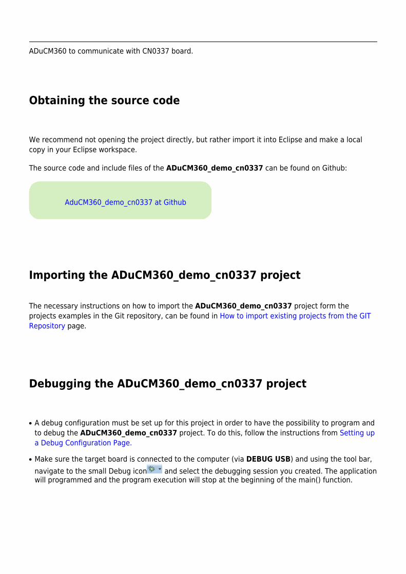
ADuCM360 to communicate with CN0337 board.
Obtaining the source code
We recommend not opening the project directly, but rather import it into Eclipse and make a localcopy in your Eclipse workspace.
The source code and include files of the ADuCM360_demo_cn0337 can be found on Github:
AduCM360_demo_cn0337 at Github
Importing the ADuCM360_demo_cn0337 project
The necessary instructions on how to import the ADuCM360_demo_cn0337 project form theprojects examples in the Git repository, can be found in How to import existing projects from the GITRepository page.
Debugging the ADuCM360_demo_cn0337 project
A debug configuration must be set up for this project in order to have the possibility to program and●
to debug the ADuCM360_demo_cn0337 project. To do this, follow the instructions from Setting upa Debug Configuration Page.
Make sure the target board is connected to the computer (via DEBUG USB) and using the tool bar,●
navigate to the small Debug icon and select the debugging session you created. The applicationwill programmed and the program execution will stop at the beginning of the main() function.
Use step-by-step execution or directly run the program.●
After completion of the steps above the program will remain written into the system flash and it willrun by default every time the board is powered up.
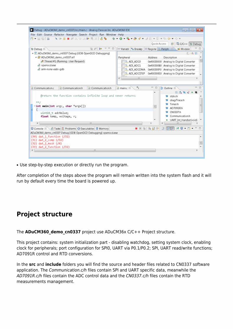
Project structure
The ADuCM360_demo_cn0337 project use ADuCM36x C/C++ Project structure.
This project contains: system initialization part - disabling watchdog, setting system clock, enablingclock for peripherals; port configuration for SPI0, UART via P0.1/P0.2; SPI, UART read/write functions;AD7091R control and RTD conversions.
In the src and include folders you will find the source and header files related to CN0337 softwareapplication. The Communication.c/h files contain SPI and UART specific data, meanwhile theAD7091R.c/h files contain the ADC control data and the CN0337.c/h files contain the RTDmeasurements management.
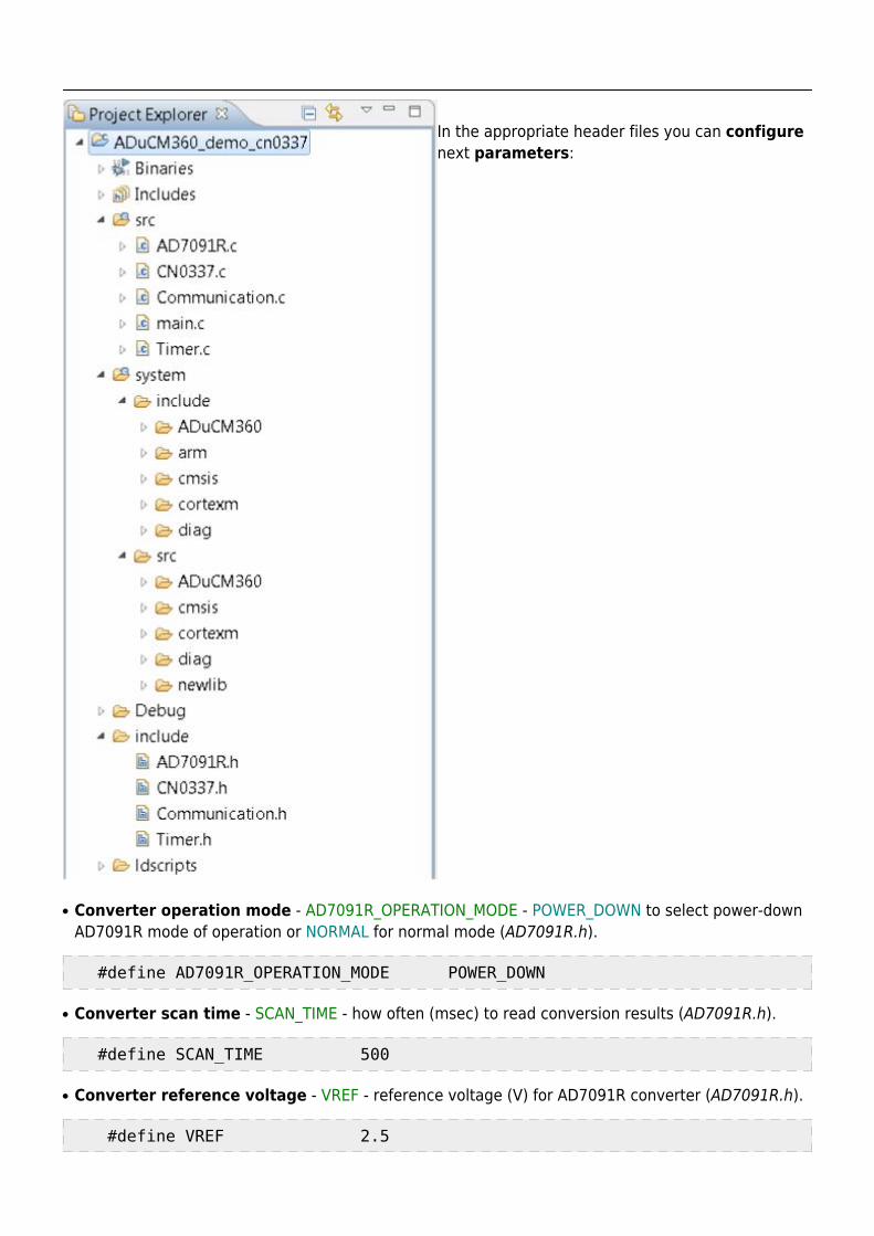
In the appropriate header files you can configurenext parameters:
Converter operation mode - AD7091R_OPERATION_MODE - POWER_DOWN to select power-down●
AD7091R mode of operation or NORMAL for normal mode (AD7091R.h).
#define AD7091R_OPERATION_MODE POWER_DOWN
Converter scan time - SCAN_TIME - how often (msec) to read conversion results (AD7091R.h).●
#define SCAN_TIME 500
Converter reference voltage - VREF - reference voltage (V) for AD7091R converter (AD7091R.h).●
#define VREF 2.5
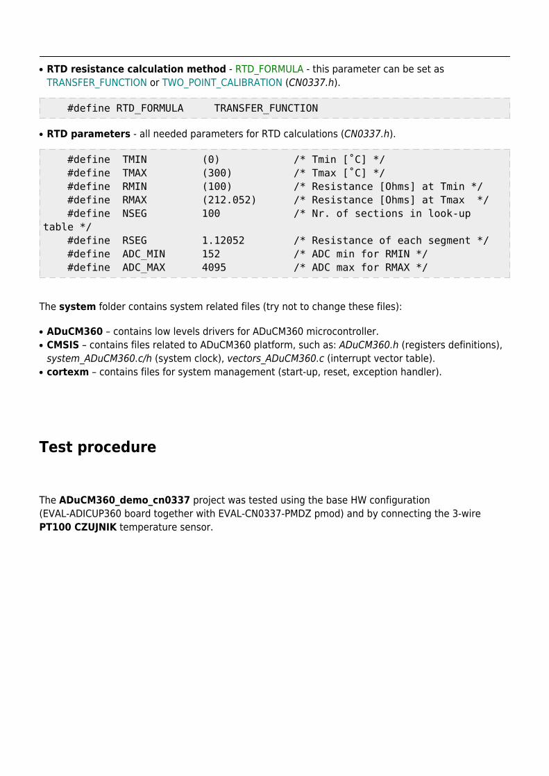
RTD resistance calculation method - RTD_FORMULA - this parameter can be set as●
TRANSFER_FUNCTION or TWO_POINT_CALIBRATION (CN0337.h).
#define RTD_FORMULA TRANSFER_FUNCTION
RTD parameters - all needed parameters for RTD calculations (CN0337.h).●
#define TMIN (0) /* Tmin [˚C] */ #define TMAX (300) /* Tmax [˚C] */ #define RMIN (100) /* Resistance [Ohms] at Tmin */ #define RMAX (212.052) /* Resistance [Ohms] at Tmax */ #define NSEG 100 /* Nr. of sections in look-uptable */ #define RSEG 1.12052 /* Resistance of each segment */ #define ADC_MIN 152 /* ADC min for RMIN */ #define ADC_MAX 4095 /* ADC max for RMAX */
The system folder contains system related files (try not to change these files):
ADuCM360 – contains low levels drivers for ADuCM360 microcontroller.●
CMSIS – contains files related to ADuCM360 platform, such as: ADuCM360.h (registers definitions),●
system_ADuCM360.c/h (system clock), vectors_ADuCM360.c (interrupt vector table).cortexm – contains files for system management (start-up, reset, exception handler).●
Test procedure
The ADuCM360_demo_cn0337 project was tested using the base HW configuration(EVAL-ADICUP360 board together with EVAL-CN0337-PMDZ pmod) and by connecting the 3-wirePT100 CZUJNIK temperature sensor.
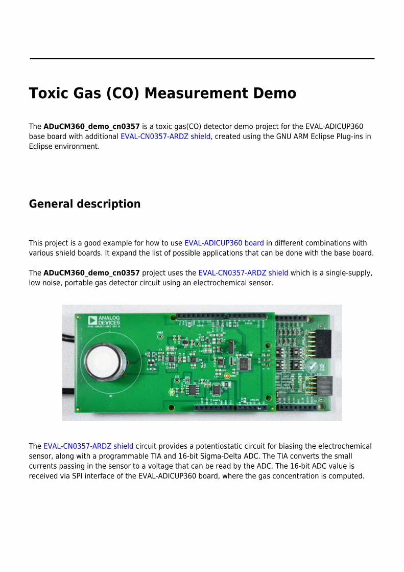
Toxic Gas (CO) Measurement Demo
The ADuCM360_demo_cn0357 is a toxic gas(CO) detector demo project for the EVAL-ADICUP360base board with additional EVAL-CN0357-ARDZ shield, created using the GNU ARM Eclipse Plug-ins inEclipse environment.
General description
This project is a good example for how to use EVAL-ADICUP360 board in different combinations withvarious shield boards. It expand the list of possible applications that can be done with the base board.
The ADuCM360_demo_cn0357 project uses the EVAL-CN0357-ARDZ shield which is a single-supply,low noise, portable gas detector circuit using an electrochemical sensor.
The EVAL-CN0357-ARDZ shield circuit provides a potentiostatic circuit for biasing the electrochemicalsensor, along with a programmable TIA and 16-bit Sigma-Delta ADC. The TIA converts the smallcurrents passing in the sensor to a voltage that can be read by the ADC. The 16-bit ADC value isreceived via SPI interface of the EVAL-ADICUP360 board, where the gas concentration is computed.
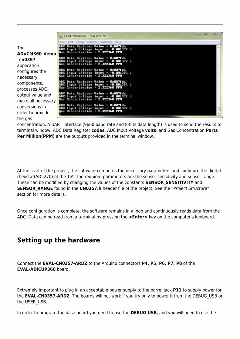
TheADuCM360_demo_cn0357applicationconfigures thenecessarycomponents,processes ADCoutput value andmake all necessaryconversions inorder to providethe gasconcentration. A UART interface (9600 baud rate and 8-bits data length) is used to send the results toterminal window: ADC Data Register codes, ADC Input Voltage volts, and Gas Concentration PartsPer Million(PPM) are the outputs provided in the terminal window.
At the start of the project, the software computes the necessary parameters and configure the digitalrheostat(AD5270) of the TIA. The required parameters are the sensor sensitivity and sensor range.These can be modified by changing the values of the constants SENSOR_SENSITIVITY andSENSOR_RANGE found in the CN0357.h header file of the project. See the “Project Structure”section for more details.
Once configuration is complete, the software remains in a loop and continuously reads data from theADC. Data can be read from a terminal by pressing the <Enter> key on the computer's keyboard.
Setting up the hardware
Connect the EVAL-CN0357-ARDZ to the Arduino connectors P4, P5, P6, P7, P8 of theEVAL-ADICUP360 board.
Extremely important to plug in an acceptable power supply to the barrel jack P11 to supply power forthe EVAL-CN0357-ARDZ. The boards will not work if you try only to power it from the DEBUG_USB orthe USER_USB.
In order to program the base board you need to use the DEBUG USB, and you will need to use the
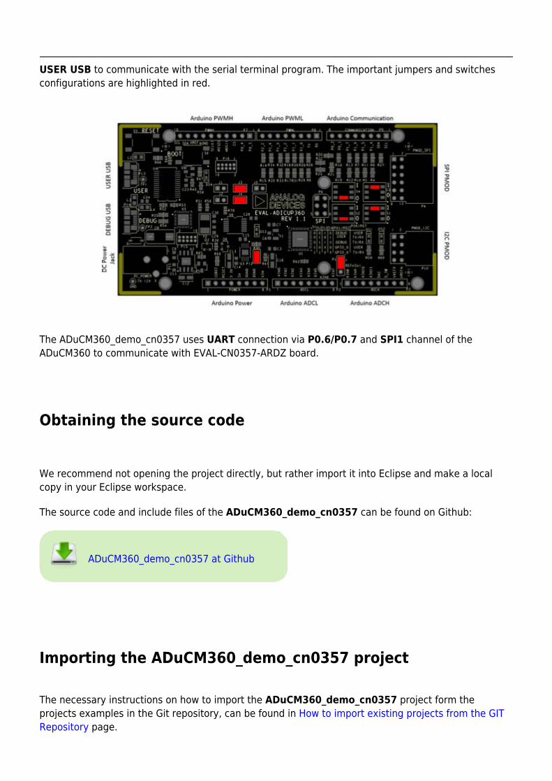
USER USB to communicate with the serial terminal program. The important jumpers and switchesconfigurations are highlighted in red.
The ADuCM360_demo_cn0357 uses UART connection via P0.6/P0.7 and SPI1 channel of theADuCM360 to communicate with EVAL-CN0357-ARDZ board.
Obtaining the source code
We recommend not opening the project directly, but rather import it into Eclipse and make a localcopy in your Eclipse workspace.
The source code and include files of the ADuCM360_demo_cn0357 can be found on Github:
ADuCM360_demo_cn0357 at Github
Importing the ADuCM360_demo_cn0357 project
The necessary instructions on how to import the ADuCM360_demo_cn0357 project form theprojects examples in the Git repository, can be found in How to import existing projects from the GITRepository page.
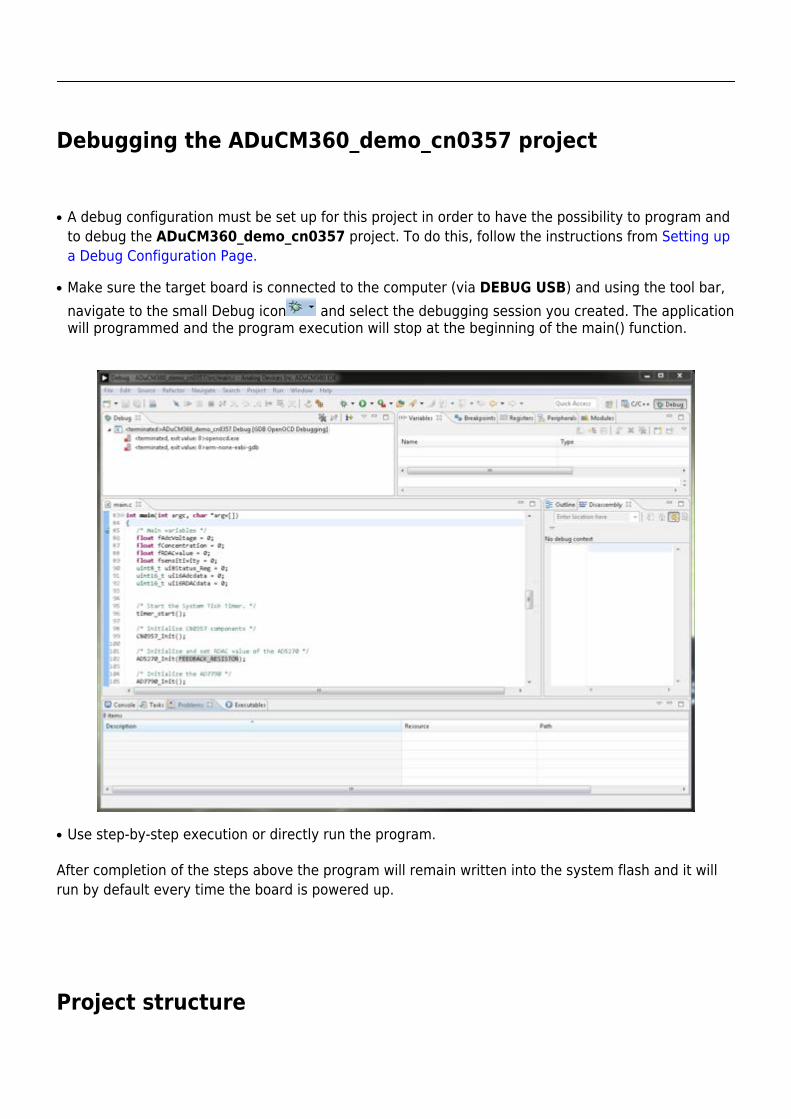
Debugging the ADuCM360_demo_cn0357 project
A debug configuration must be set up for this project in order to have the possibility to program and●
to debug the ADuCM360_demo_cn0357 project. To do this, follow the instructions from Setting upa Debug Configuration Page.
Make sure the target board is connected to the computer (via DEBUG USB) and using the tool bar,●
navigate to the small Debug icon and select the debugging session you created. The applicationwill programmed and the program execution will stop at the beginning of the main() function.
Use step-by-step execution or directly run the program.●
After completion of the steps above the program will remain written into the system flash and it willrun by default every time the board is powered up.
Project structure
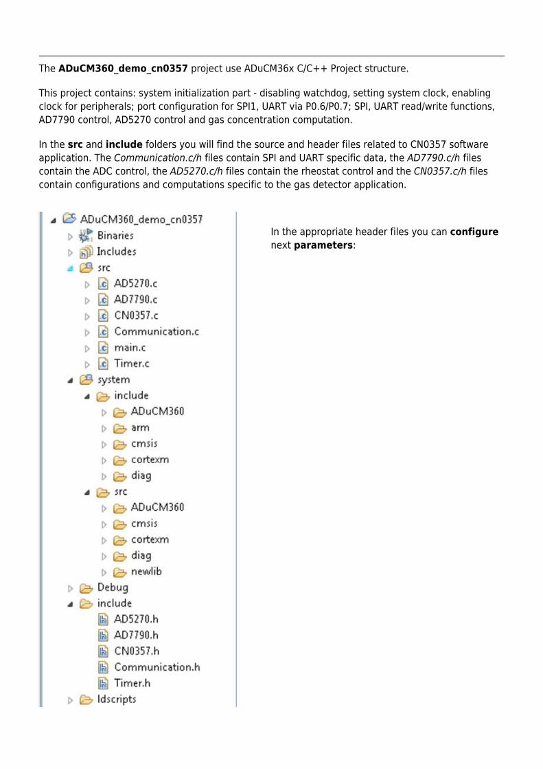
The ADuCM360_demo_cn0357 project use ADuCM36x C/C++ Project structure.
This project contains: system initialization part - disabling watchdog, setting system clock, enablingclock for peripherals; port configuration for SPI1, UART via P0.6/P0.7; SPI, UART read/write functions,AD7790 control, AD5270 control and gas concentration computation.
In the src and include folders you will find the source and header files related to CN0357 softwareapplication. The Communication.c/h files contain SPI and UART specific data, the AD7790.c/h filescontain the ADC control, the AD5270.c/h files contain the rheostat control and the CN0357.c/h filescontain configurations and computations specific to the gas detector application.
In the appropriate header files you can configurenext parameters:
Sensor Range - SENSOR_RANGE - maximum value of the gas conentration (ppm) that can be●
detected by the electrochemical gas sensor being used (CN0357.h).
#define SENSOR_RANGE 2000
Sensor Sensitivity - SENSOR_SENSITIVITY - sensitivity (nA/ppm) of the electrochemical sensor●
being used (CN0357.h).
#define SENSOR_SENSITIVITY 65
The system folder contains system related files (try not to change these files):
ADuCM360 – contains low levels drivers for ADuCM360 microcontroller.●
CMSIS – contains files related to ADuCM360 platform, such as: ADuCM360.h (registers definitions),●
system_ADuCM360.c/h (system clock), vectors_ADuCM360.c (interrupt vector table).cortexm – contains files for system management (start-up, reset, exception handler).●
Help and Support
This page wants to help you when you have a specific issue which required a different approach orwhen the wiki information are not enough.
ADuCM360 questions
If you have any questions regarding the base platform or any of the shields/pmods or areexperiencing any problems while using the boards or while following any of the user guides feel freeto ask us a question. Questions can be asked on our EngineerZone support community.
When asking a question please take the time to give a detailed description of your problem. If you areexperiencing a problem please state the steps you have executed, the result you expected you wouldget and the result you actually got. By doing so you enable us to provide you precise and detailedanswers in a timely manner.
Before asking questions please take the time to check if somebody else already asked the samequestion and already got an answer.
IDE questions
If you need additional information about Eclipse IDE which is part of the EVAL-ADICUP360 Tool Chainyou can visit GNU ARM Eclipse page.

ADICUP360 Compliance Results
Introduction
Regulatory compliance means conforming to a rule, such as a specification, policy, standard or law.Most products that ships into a country need to pass a variety of tests and regulations specific to thatcountry.
Due to the increasing number of regulations, organizations are increasingly adopting the use ofconsolidated sets of compliance controls. This means once you normally get one, you can have themall.
Reports
The ADICUP360 passes all requirements of the CE tests.
ADICUP360 EMC emissions and immunity test report●
What are all these logos?
CE Mark : a mandatory conformity marking for certain products sold within the European●
Economic Area (EEA).Electrical and Electronic Equipment Waste Directive : a European Community directive●
2002/96/EC on waste electrical and electronic equipment (WEEE).Federal Communications Commission : is an independent agency of the United States●
government, this logo means we pass part 15, class B.
![arXiv:1001.4043v7 [math.CA] 17 Mar 2011arXiv:1001.4043v7 [math.CA] 17 Mar 2011 A TWO WEIGHT INEQUALITY FOR THE HILBERT TRANSFORM ASSUMING AN ENERGY HYPOTHESIS MICHAEL T. LACEY, ERIC](https://static.fdocument.org/doc/165x107/5e45b0737116a251e34b7be6/arxiv10014043v7-mathca-17-mar-2011-arxiv10014043v7-mathca-17-mar-2011.jpg)