Intro to Arduino I/O · PDF file1 Intro to Arduino I/O ~ Programming beyond the pins Ed Nisley...
42
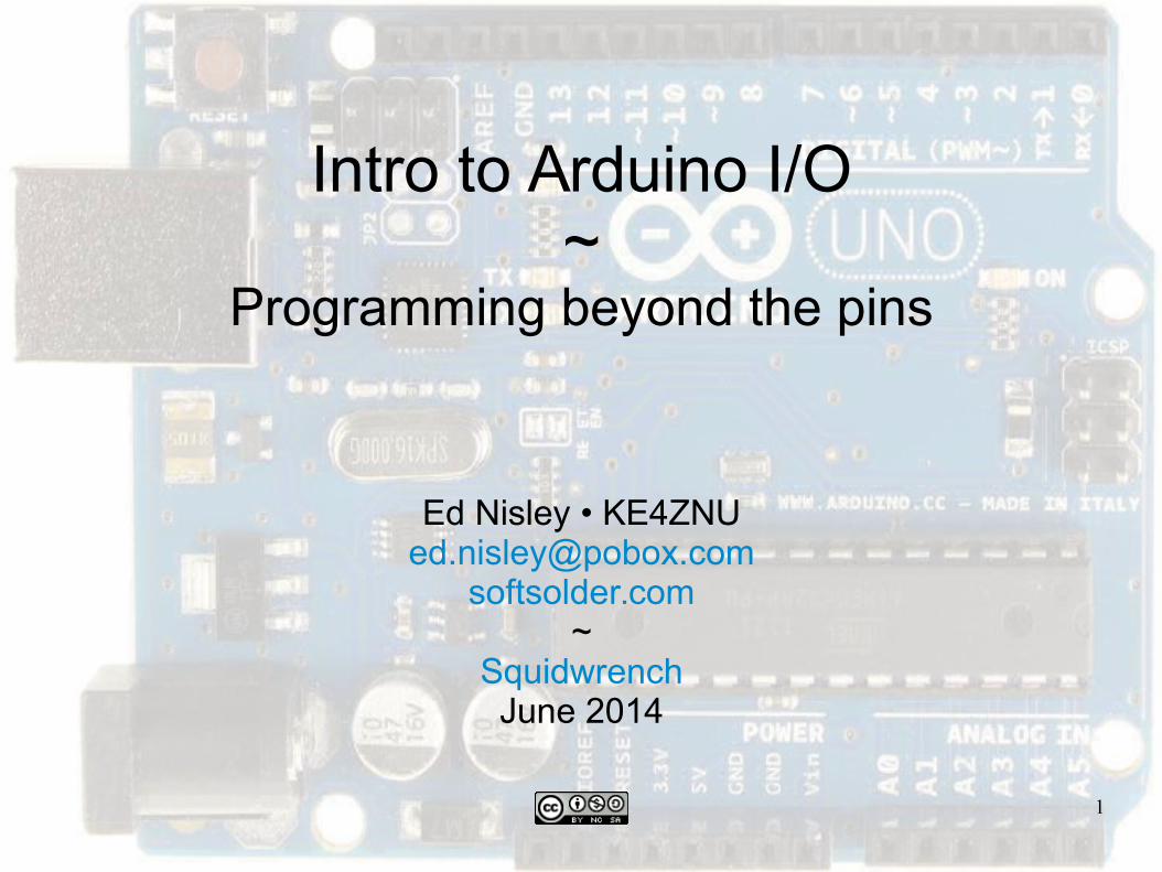
1 Intro to Arduino I/O ~ Programming beyond the pins Ed Nisley • KE4ZNU [email protected] softsolder.com ~ Squidwrench June 2014
Transcript of Intro to Arduino I/O · PDF file1 Intro to Arduino I/O ~ Programming beyond the pins Ed Nisley...
1
Intro to Arduino I/O~
Programming beyond the pins
Ed Nisley • [email protected]
softsolder.com~
SquidwrenchJune 2014

2
The Big Picture
Arduino stuff
PCB with known pin layout & spacing
Power Source: USB or DC wall wart
Atmel Atmega168 / 328 μC + USB Interface
Digital & analog I/O pins
Your stuff
Draws power (ideally 5 V, maybe 12 V, or ...)
Connects to μC I/O pins (5 V only!)
Must play well with Arduino

3
Useful Background
Dimensions & units
E = voltage: volt V, millivolt mV
I = current: ampere A, milliampere mA = A/1000
P = power: watt W, milliwatt mW = W/1000
R = resistance: ohm Ω, kilohm kΩ = Ω • 1000
L = inductance: henry H, millihenry mH = H/1000
Ohm’s Law: E = I•R (for resistors with known R)
Power: P = I2•R = E2/R = E•I (for anything)
You need a calculator and a multimeter ... now!
4
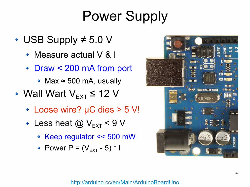
Power Supply
USB Supply ≠ 5.0 V
Measure actual V & I
Draw < 200 mA from port
Max ≈ 500 mA, usually
Wall Wart VEXT ≤ 12 V
Loose wire? μC dies > 5 V!
Less heat @ VEXT < 9 V
Keep regulator << 500 mW
Power P = (VEXT - 5) * I
http://arduino.cc/en/Main/ArduinoBoardUno

5
Plug It In, It Turns On
Getting Started Instructions
Fetch & Install Arduino 1.0.5 IDE
Windows / Linux / Mac
Arduino ↔ USB Cable ↔ PC
Beware cheap cables!
Select the right “serial” port
Select proper microcontroller
Load / run / change Blink sketch
Install Libraries?
New in 1.0.5: Sketch → Import Library
http://arduino.cc/
6
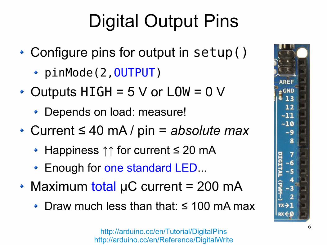
Digital Output Pins
Configure pins for output in setup()
pinMode(2,OUTPUT)
Outputs HIGH = 5 V or LOW = 0 V
Depends on load: measure!
Current ≤ 40 mA / pin = absolute max
Happiness ↑↑ for current ≤ 20 mA
Enough for one standard LED...
Maximum total μC current = 200 mA
Draw much less than that: ≤ 100 mA max
http://arduino.cc/en/Tutorial/DigitalPinshttp://arduino.cc/en/Reference/DigitalWrite
7
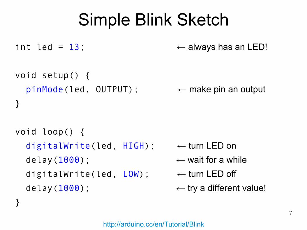
Simple Blink Sketch
int led = 13; ← always has an LED!
void setup() {
pinMode(led, OUTPUT); ← make pin an output
}
void loop() {
digitalWrite(led, HIGH); ← turn LED on
delay(1000); ← wait for a while
digitalWrite(led, LOW); ← turn LED off
delay(1000); ← try a different value!
}
http://arduino.cc/en/Tutorial/Blink
8
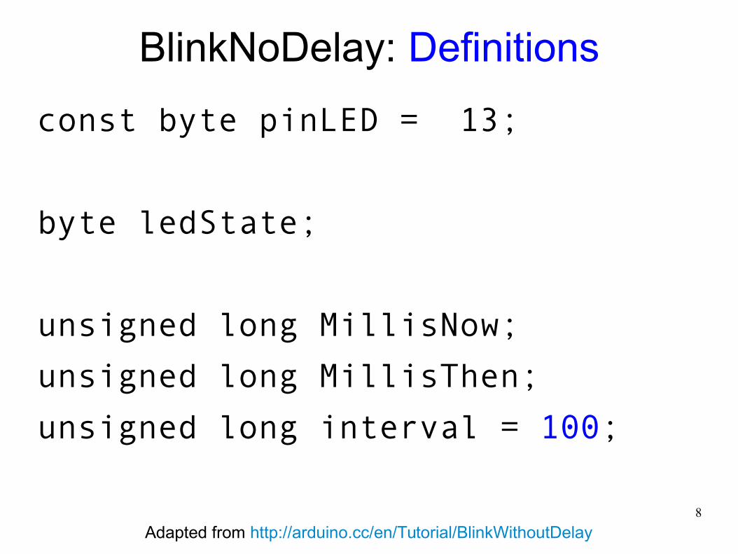
BlinkNoDelay: Definitions
const byte pinLED = 13;
byte ledState;
unsigned long MillisNow;
unsigned long MillisThen;
unsigned long interval = 100;
Adapted from http://arduino.cc/en/Tutorial/BlinkWithoutDelay
9
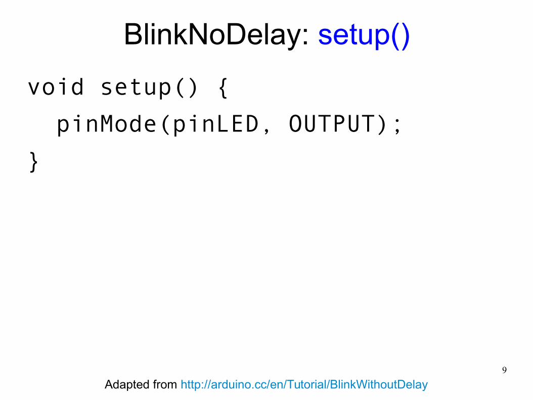
BlinkNoDelay: setup()
void setup() {
pinMode(pinLED, OUTPUT);
}
Adapted from http://arduino.cc/en/Tutorial/BlinkWithoutDelay
10
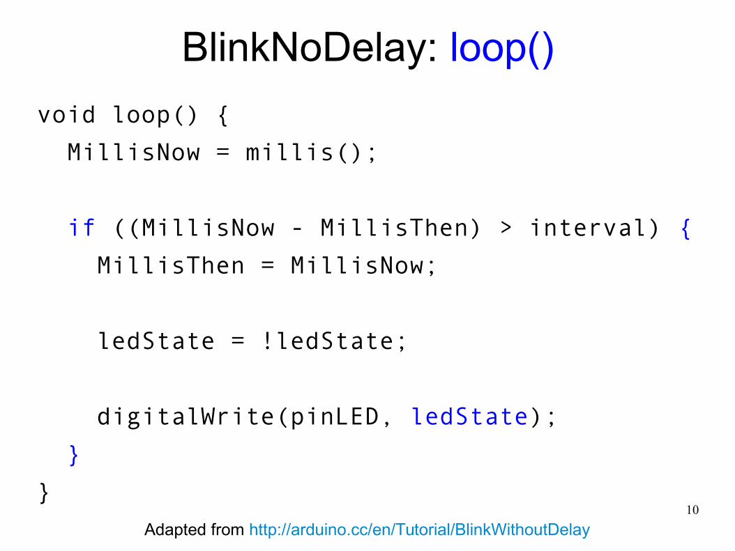
BlinkNoDelay: loop()
void loop() {
MillisNow = millis();
if ((MillisNow - MillisThen) > interval) {
MillisThen = MillisNow;
ledState = !ledState;
digitalWrite(pinLED, ledState);
}
}
Adapted from http://arduino.cc/en/Tutorial/BlinkWithoutDelay
11
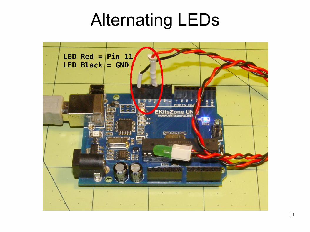
Alternating LEDs
12
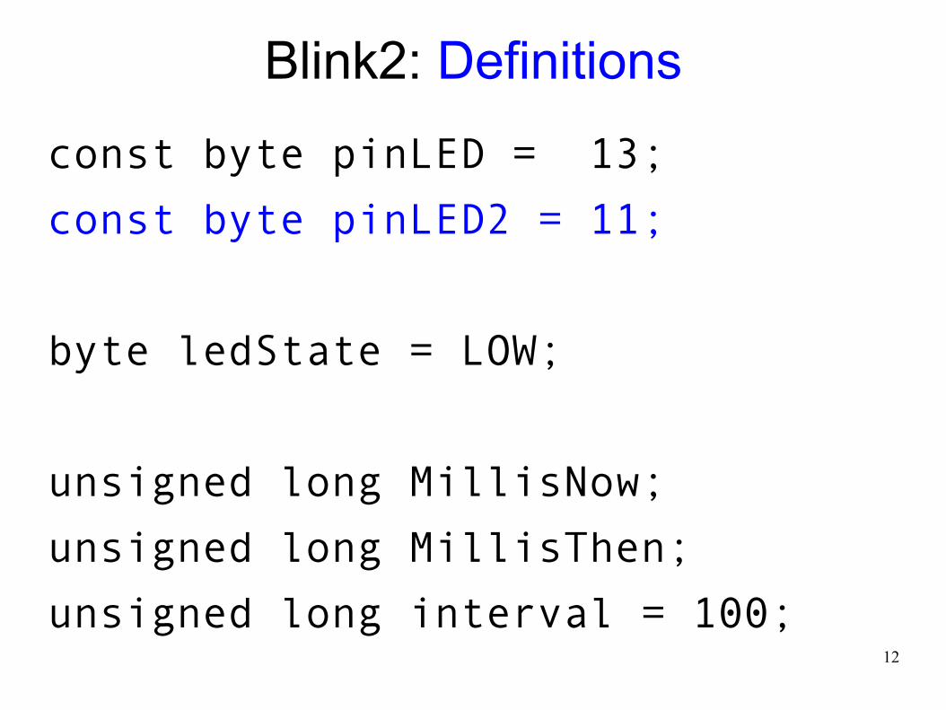
Blink2: Definitions
const byte pinLED = 13;
const byte pinLED2 = 11;
byte ledState = LOW;
unsigned long MillisNow;
unsigned long MillisThen;
unsigned long interval = 100;
13
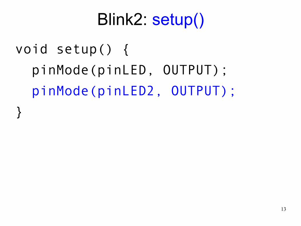
Blink2: setup()
void setup() {
pinMode(pinLED, OUTPUT);
pinMode(pinLED2, OUTPUT);
}
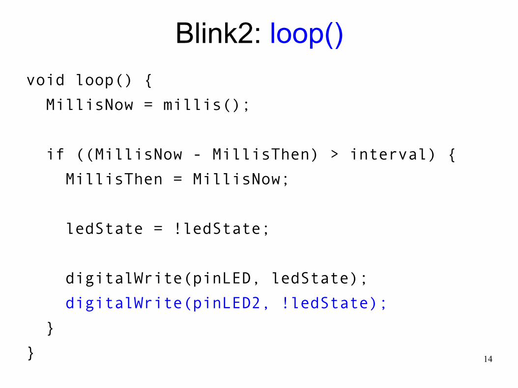
14
Blink2: loop()
void loop() {
MillisNow = millis();
if ((MillisNow - MillisThen) > interval) {
MillisThen = MillisNow;
ledState = !ledState;
digitalWrite(pinLED, ledState);
digitalWrite(pinLED2, !ledState);
}
}
15
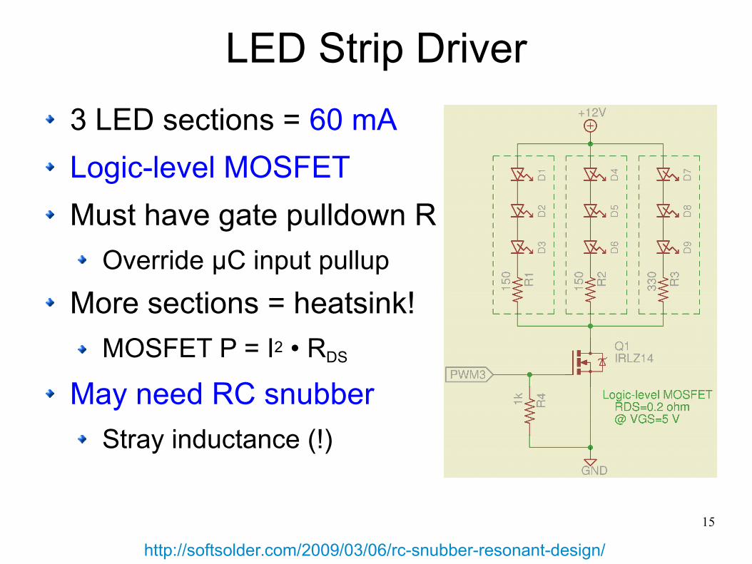
LED Strip Driver
3 LED sections = 60 mA
Logic-level MOSFET
Must have gate pulldown R
Override μC input pullup
More sections = heatsink!
MOSFET P = I2 • RDS
May need RC snubber
Stray inductance (!)
http://softsolder.com/2009/03/06/rc-snubber-resonant-design/
16
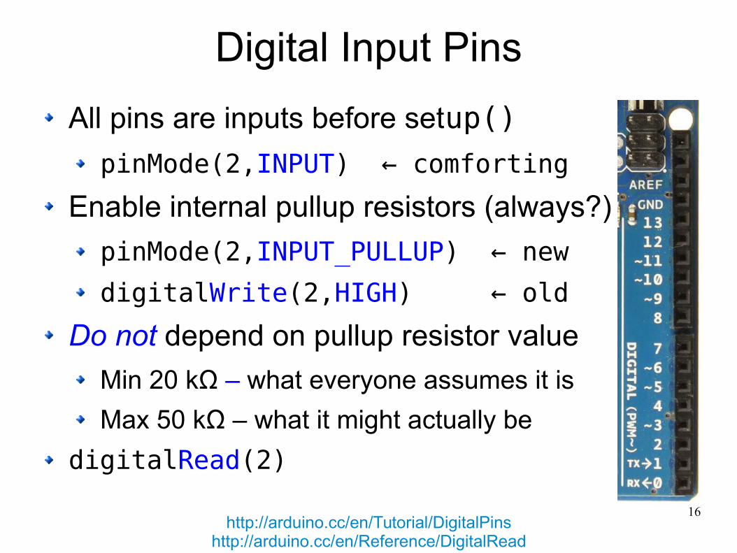
Digital Input Pins
All pins are inputs before setup()
pinMode(2,INPUT) ← comforting
Enable internal pullup resistors (always?)
pinMode(2,INPUT_PULLUP) ← new
digitalWrite(2,HIGH) ← old
Do not depend on pullup resistor value
Min 20 kΩ – what everyone assumes it is
Max 50 kΩ – what it might actually be
digitalRead(2)
http://arduino.cc/en/Tutorial/DigitalPinshttp://arduino.cc/en/Reference/DigitalRead
17
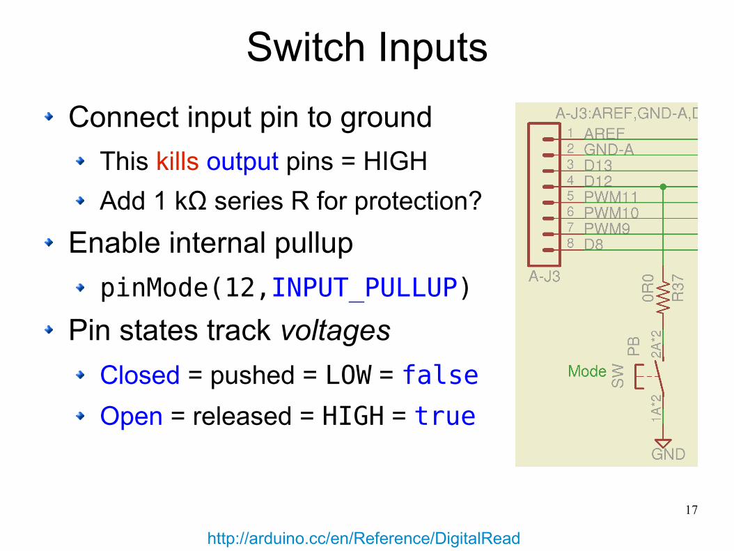
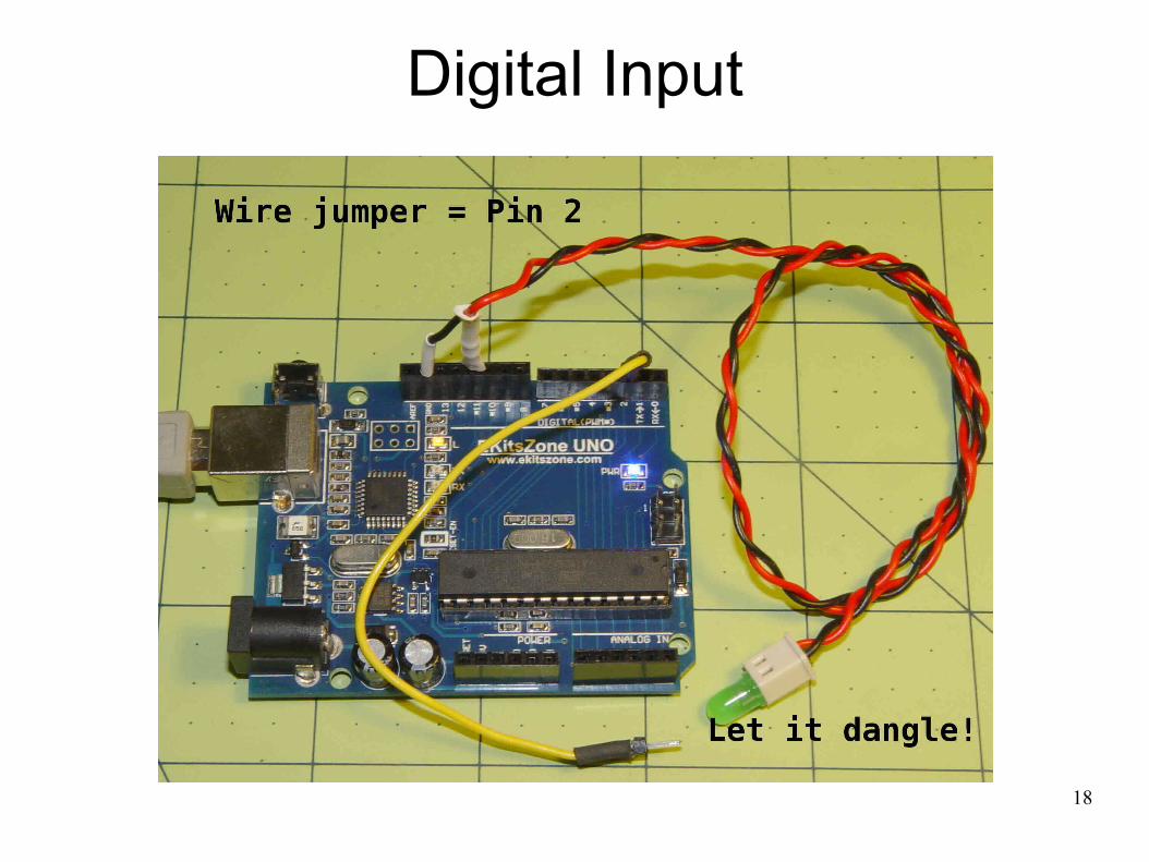
Switch Inputs
Connect input pin to ground
This kills output pins = HIGH
Add 1 kΩ series R for protection?
Enable internal pullup
pinMode(12,INPUT_PULLUP)
Pin states track voltages
Closed = pushed = LOW = false
Open = released = HIGH = true
http://arduino.cc/en/Reference/DigitalRead
18
Digital Input
19
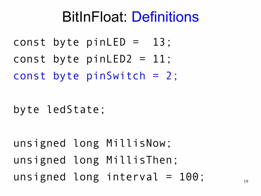
BitInFloat: Definitions
const byte pinLED = 13;
const byte pinLED2 = 11;
const byte pinSwitch = 2;
byte ledState;
unsigned long MillisNow;
unsigned long MillisThen;
unsigned long interval = 100;
20
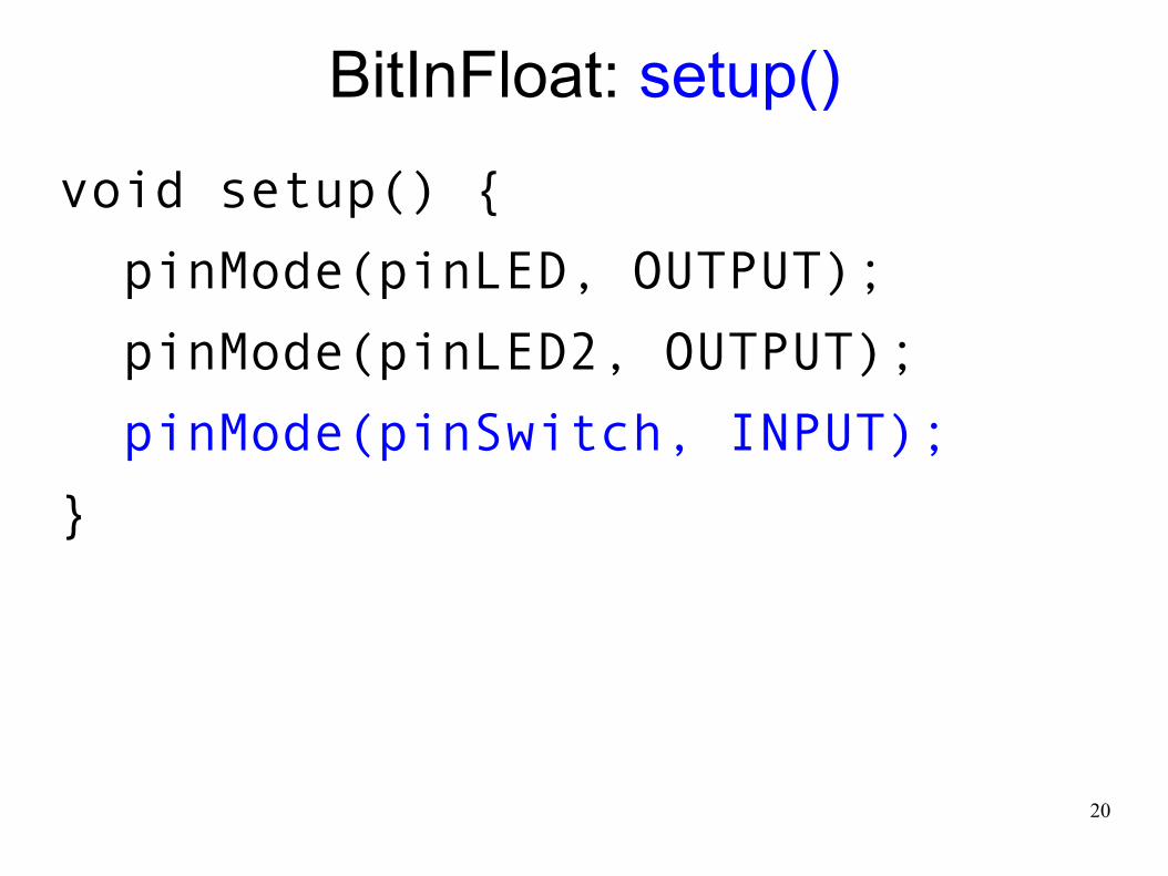
BitInFloat: setup()
void setup() {
pinMode(pinLED, OUTPUT);
pinMode(pinLED2, OUTPUT);
pinMode(pinSwitch, INPUT);
}
21
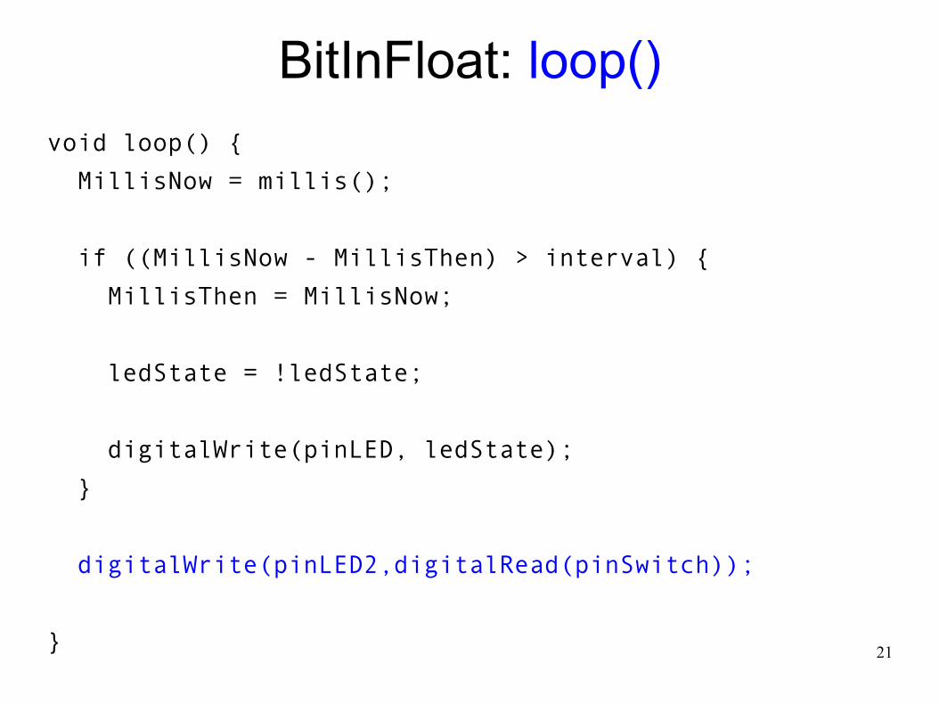
BitInFloat: loop()
void loop() {
MillisNow = millis();
if ((MillisNow - MillisThen) > interval) {
MillisThen = MillisNow;
ledState = !ledState;
digitalWrite(pinLED, ledState);
}
digitalWrite(pinLED2,digitalRead(pinSwitch));
}
22
BitInFloat
Is that floating wire LOW or HIGH?
Why does waving your hand change it?
How often will you make this mistake?
23
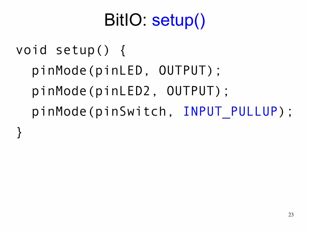
BitIO: setup()
void setup() {
pinMode(pinLED, OUTPUT);
pinMode(pinLED2, OUTPUT);
pinMode(pinSwitch, INPUT_PULLUP);
}
24
BitIO
Now, is that floating input LOW or HIGH?
What could possibly change it?
25
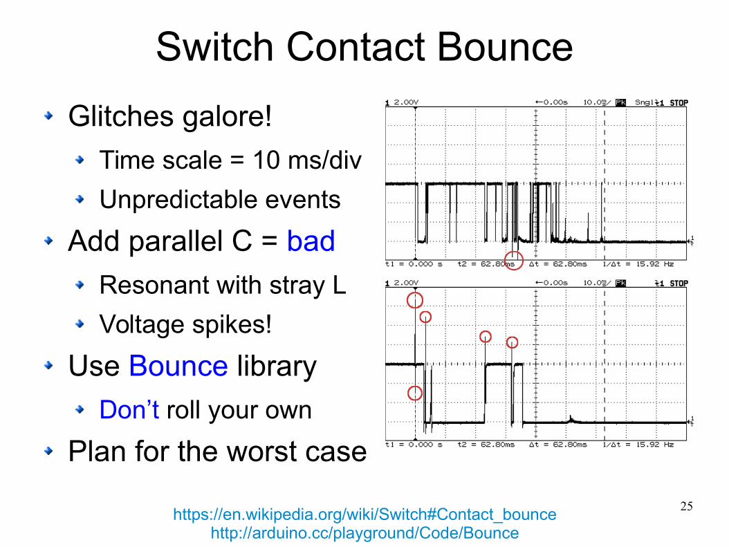
Switch Contact Bounce
Glitches galore!
Time scale = 10 ms/div
Unpredictable events
Add parallel C = bad
Resonant with stray L
Voltage spikes!
Use Bounce library
Don’t roll your own
Plan for the worst case
https://en.wikipedia.org/wiki/Switch#Contact_bouncehttp://arduino.cc/playground/Code/Bounce
26
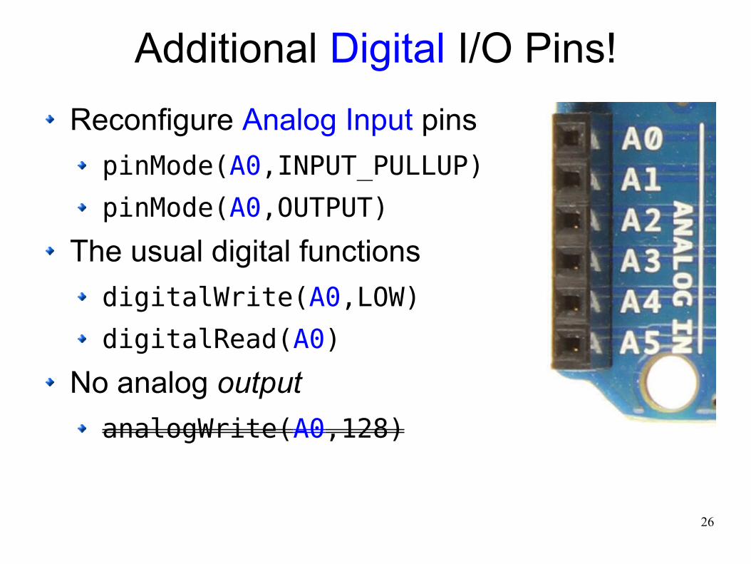
Additional Digital I/O Pins!
Reconfigure Analog Input pins
pinMode(A0,INPUT_PULLUP)
pinMode(A0,OUTPUT)
The usual digital functions
digitalWrite(A0,LOW)
digitalRead(A0)
No analog output
analogWrite(A0,128)
27
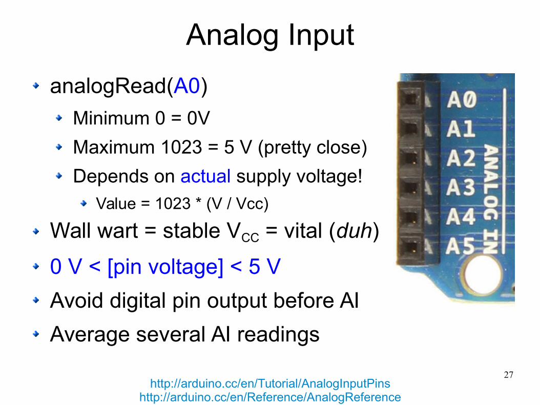
Analog Input
analogRead(A0)
Minimum 0 = 0V
Maximum 1023 = 5 V (pretty close)
Depends on actual supply voltage!
Value = 1023 * (V / Vcc)
Wall wart = stable VCC = vital (duh)
0 V < [pin voltage] < 5 V
Avoid digital pin output before AI
Average several AI readings
http://arduino.cc/en/Tutorial/AnalogInputPinshttp://arduino.cc/en/Reference/AnalogReference

28
Analog Input
29
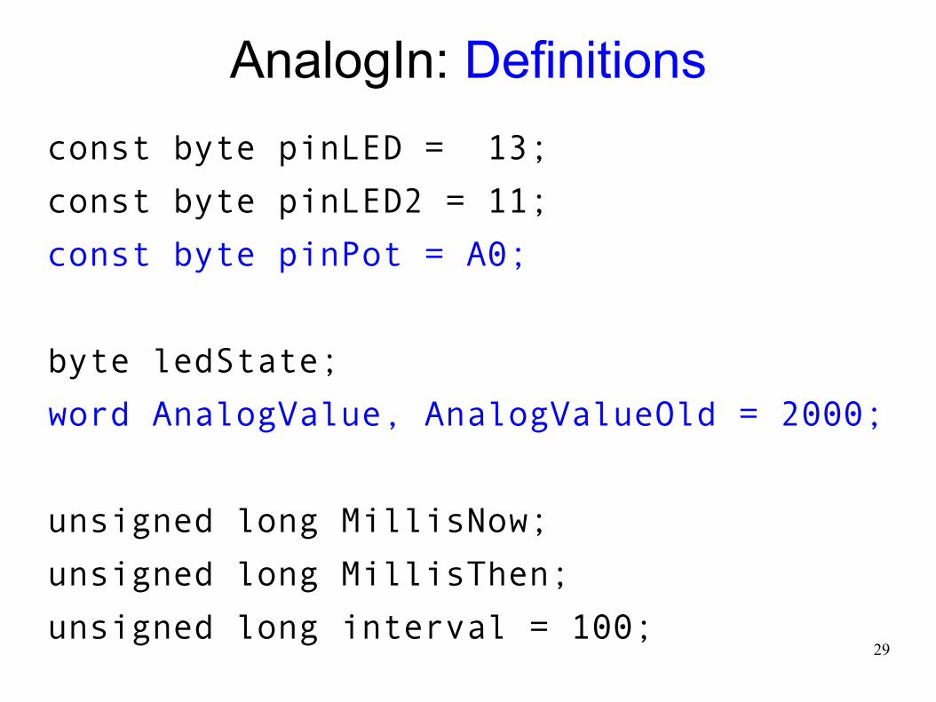
AnalogIn: Definitions
const byte pinLED = 13;
const byte pinLED2 = 11;
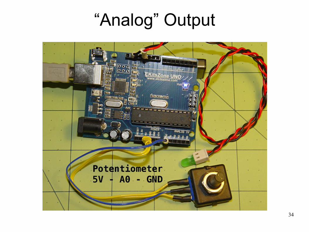
const byte pinPot = A0;
byte ledState;
word AnalogValue, AnalogValueOld = 2000;
unsigned long MillisNow;
unsigned long MillisThen;
unsigned long interval = 100;

30
AnalogIn: setup()
void setup() {
pinMode(pinLED, OUTPUT);
pinMode(pinLED2, OUTPUT);
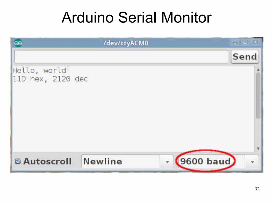
Serial.begin(9600);
Serial.println("Hello, world!");
}
31
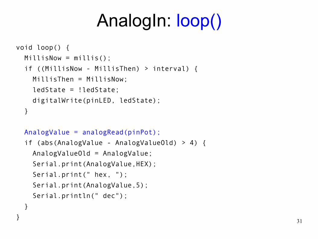
AnalogIn: loop()void loop() {
MillisNow = millis();
if ((MillisNow - MillisThen) > interval) {
MillisThen = MillisNow;
ledState = !ledState;
digitalWrite(pinLED, ledState);
}
AnalogValue = analogRead(pinPot);
if (abs(AnalogValue - AnalogValueOld) > 4) {
AnalogValueOld = AnalogValue;
Serial.print(AnalogValue,HEX);
Serial.print(" hex, ");
Serial.print(AnalogValue,5);
Serial.println(" dec");
}
}
32
Arduino Serial Monitor
33
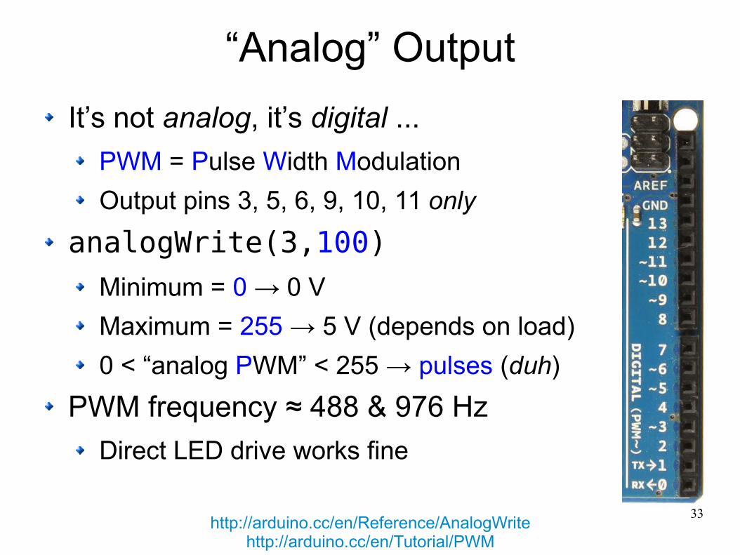
“Analog” Output
It’s not analog, it’s digital ...
PWM = Pulse Width Modulation
Output pins 3, 5, 6, 9, 10, 11 only
analogWrite(3,100)
Minimum = 0 → 0 V
Maximum = 255 → 5 V (depends on load)
0 < “analog PWM” < 255 → pulses (duh)
PWM frequency ≈ 488 & 976 Hz
Direct LED drive works fine
http://arduino.cc/en/Reference/AnalogWritehttp://arduino.cc/en/Tutorial/PWM
34
“Analog” Output
35
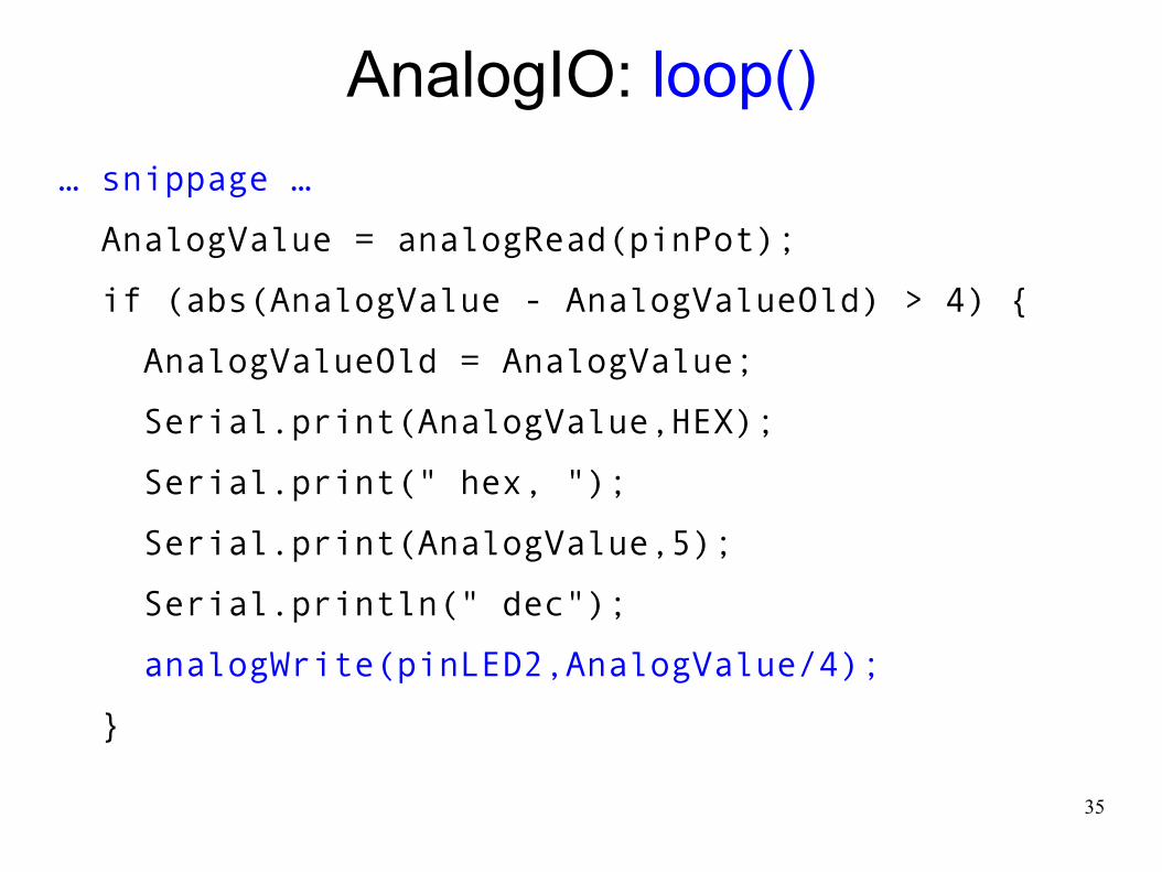
AnalogIO: loop()
… snippage …
AnalogValue = analogRead(pinPot);
if (abs(AnalogValue - AnalogValueOld) > 4) {
AnalogValueOld = AnalogValue;
Serial.print(AnalogValue,HEX);
Serial.print(" hex, ");
Serial.print(AnalogValue,5);
Serial.println(" dec");
analogWrite(pinLED2,AnalogValue/4);
}
36
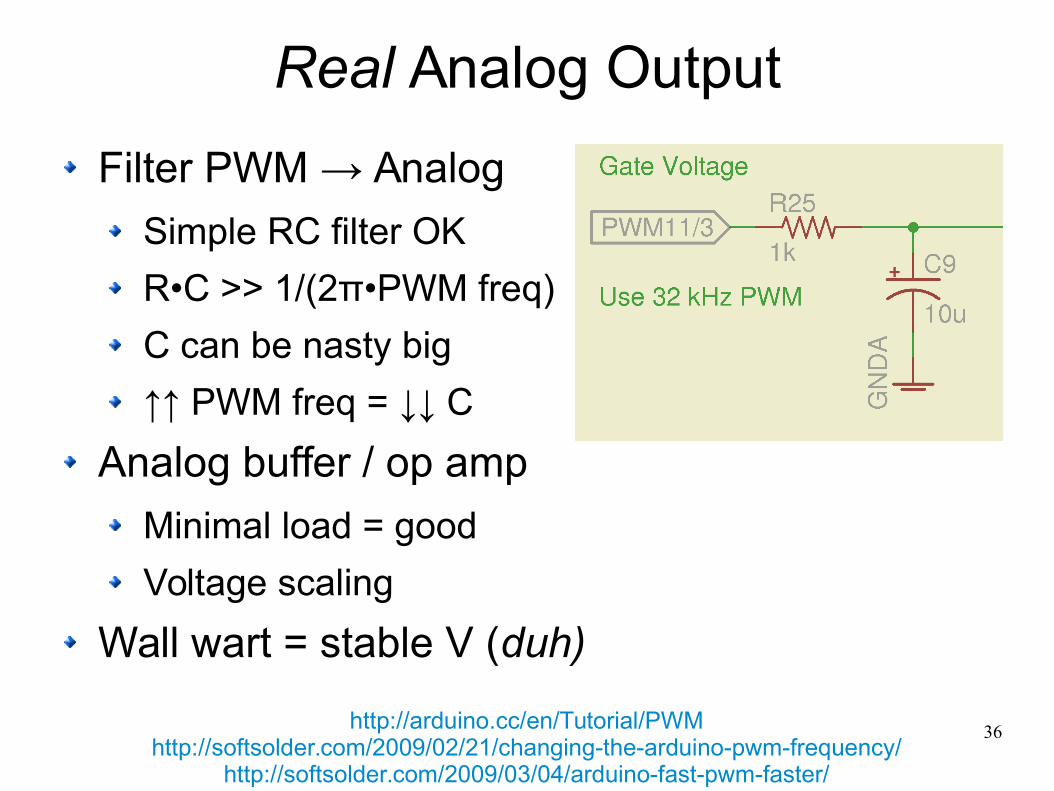
Real Analog Output
Filter PWM → Analog
Simple RC filter OK
R•C >> 1/(2π•PWM freq)
C can be nasty big
↑↑ PWM freq = ↓↓ C
Analog buffer / op amp
Minimal load = good
Voltage scaling
Wall wart = stable V (duh)
http://arduino.cc/en/Tutorial/PWMhttp://softsolder.com/2009/02/21/changing-the-arduino-pwm-frequency/
http://softsolder.com/2009/03/04/arduino-fast-pwm-faster/
37
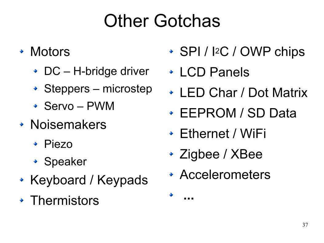
Other Gotchas
Motors
DC – H-bridge driver
Steppers – microstep
Servo – PWM
Noisemakers
Piezo
Speaker
Keyboard / Keypads
Thermistors
SPI / I2C / OWP chips
LCD Panels
LED Char / Dot Matrix
EEPROM / SD Data
Ethernet / WiFi
Zigbee / XBee
Accelerometers
...

38
Everything Else
Is
A Simple Matter of Software
39
arduino.cc/en/Reference/HomePagewww.ladyada.net/learn/arduino/index.html
todbot.com/blog/spookyarduino/www.sparkfun.com/tutorials
and, of course ...softsolder.com/tag/arduino/
More Info

40
Some web images probably copyrighted, butshown & attributed here under “fair use”
[whatever that is]
The rest is my own work
●
This work is licensed under theCreative Commons Attribution-Noncommercial-Share Alike 3.0 United States License.
To view a copy of this license, visithttp://creativecommons.org/licenses/by-nc-sa/3.0/us/
or send a letter toCreative Commons, 543 Howard Street, 5th Floor
San Francisco, California, 94105, USA.
Copyright-ish Stuff
41
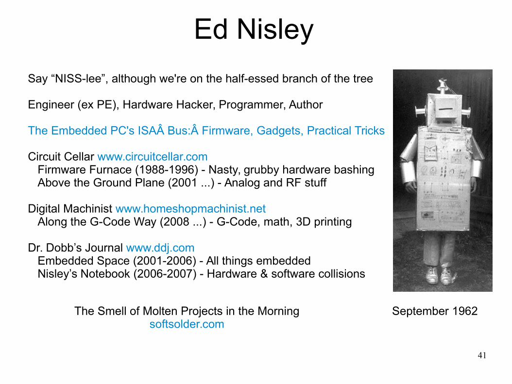
Ed Nisley
September 1962
Say “NISS-lee”, although we're on the half-essed branch of the tree
Engineer (ex PE), Hardware Hacker, Programmer, Author
The Embedded PC's ISAÂ Bus:Â Firmware, Gadgets, Practical Tricks Circuit Cellar www.circuitcellar.com Firmware Furnace (1988-1996) - Nasty, grubby hardware bashing Above the Ground Plane (2001 ...) - Analog and RF stuff
Digital Machinist www.homeshopmachinist.net Along the G-Code Way (2008 ...) - G-Code, math, 3D printing
Dr. Dobb’s Journal www.ddj.com Embedded Space (2001-2006) - All things embedded Nisley’s Notebook (2006-2007) - Hardware & software collisions
The Smell of Molten Projects in the Morningsoftsolder.com
42
If youcan’t read this
thenmake a new friend
‘way up front