Interference - Institut Teknologi...
26
Interference Part-2 Gambar: Museum Victoria Australia
Transcript of Interference - Institut Teknologi...
Interference
Part-2
Gambar: Museum Victoria Australia
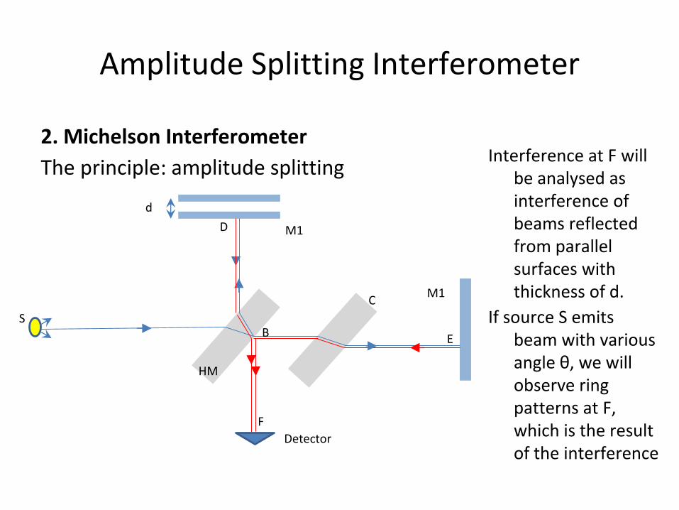
Amplitude Splitting Interferometer
2. Michelson Interferometer
The principle: amplitude splitting
HM
M1C
B
Detector
M1
S
d
D
E
F
Interference at F will be analysed as interference of beams reflected from parallel surfaces with thickness of d.
If source S emits beam with various angle θ, we will observe ring patterns at F, which is the result of the interference
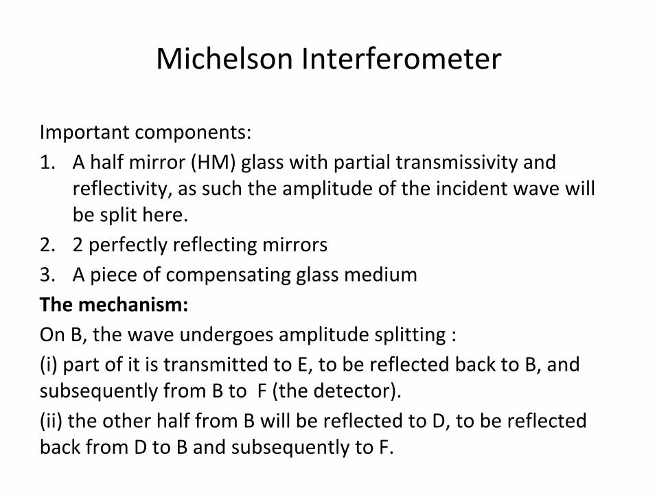
Michelson Interferometer
Important components:
1. A half mirror (HM) glass with partial transmissivity and reflectivity, as such the amplitude of the incident wave will be split here.
2. 2 perfectly reflecting mirrors
3. A piece of compensating glass medium
The mechanism:
On B, the wave undergoes amplitude splitting :
(i) part of it is transmitted to E, to be reflected back to B, and subsequently from B to F (the detector).
(ii) the other half from B will be reflected to D, to be reflected back from D to B and subsequently to F.
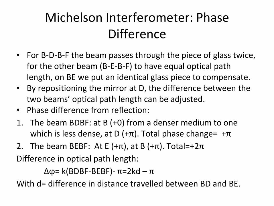
Michelson Interferometer: Phase Difference
• For B-D-B-F the beam passes through the piece of glass twice, for the other beam (B-E-B-F) to have equal optical path length, on BE we put an identical glass piece to compensate.
• By repositioning the mirror at D, the difference between the two beams’ optical path length can be adjusted.
• Phase difference from reflection:
1. The beam BDBF: at B (+0) from a denser medium to one which is less dense, at D (+π). Total phase change= +π
2. The beam BEBF: At E (+π), at B (+π). Total=+2π
Difference in optical path length:
Δϕ= k(BDBF-BEBF)- π=2kd – π
With d= difference in distance travelled between BD and BE.
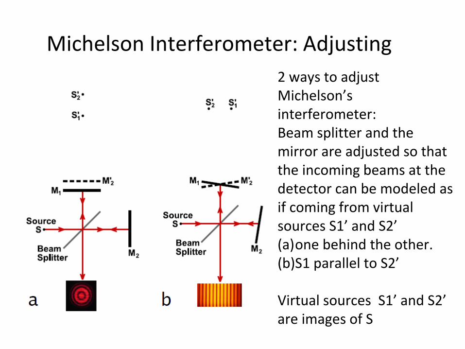
2 ways to adjust Michelson’s interferometer:Beam splitter and the mirror are adjusted so that the incoming beams at the detector can be modeled as if coming from virtual sources S1’ and S2’ (a)one behind the other.(b)S1 parallel to S2’
Virtual sources S1’ and S2’ are images of S
Michelson Interferometer: Adjusting
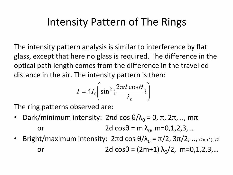
Intensity Pattern of The Rings
The intensity pattern analysis is similar to interference by flat glass, except that here no glass is required. The difference in the optical path length comes from the difference in the travelled distance in the air. The intensity pattern is then:
The ring patterns observed are:
• Dark/minimum intensity: 2πd cos θ/λ0 = 0, π, 2π, .., mπ
or 2d cosθ = m λ0, m=0,1,2,3,…
• Bright/maximum intensity: 2πd cos θ/λ0 = π/2, 3π/2, .., (2m+1)π/2
or 2d cosθ = (2m+1) λ0/2, m=0,1,2,3,…
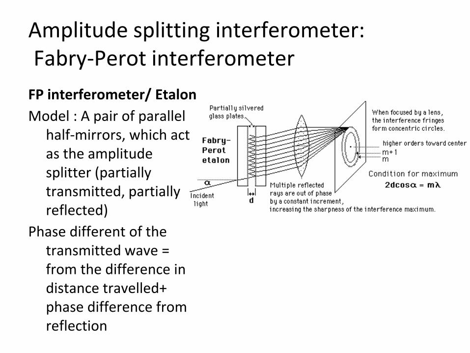
Amplitude splitting interferometer:Fabry-Perot interferometer
FP interferometer/ Etalon
Model : A pair of parallel half-mirrors, which act as the amplitude splitter (partially transmitted, partially reflected)
Phase different of the transmitted wave = from the difference in distance travelled+ phase difference from reflection
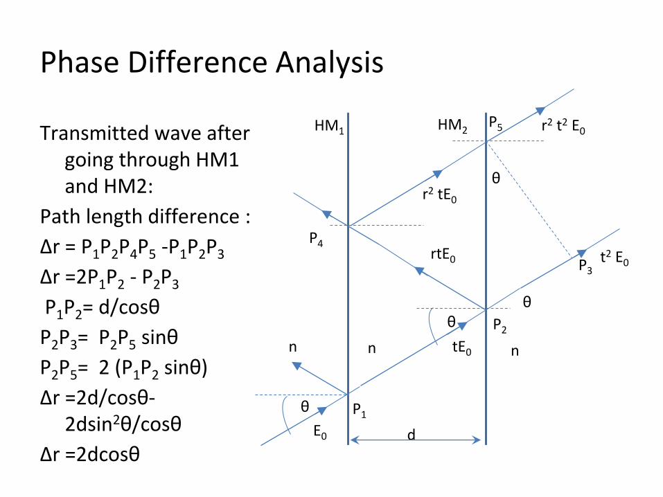
Phase Difference Analysis
Transmitted wave after going through HM1 and HM2:
Path length difference :
Δr = P1P2P4P5 -P1P2P3
Δr =2P1P2 - P2P3
P1P2= d/cosθ
P2P3= P2P5 sinθ
P2P5= 2 (P1P2 sinθ)
Δr =2d/cosθ-2dsin2θ/cosθ
Δr =2dcosθ
θθ
θ
P1
HM1
n
dE0
θ
P2
P3
P4
P5
tE0
t2 E0rtE0
r2 tE0
r2 t2 E0
n n
HM2
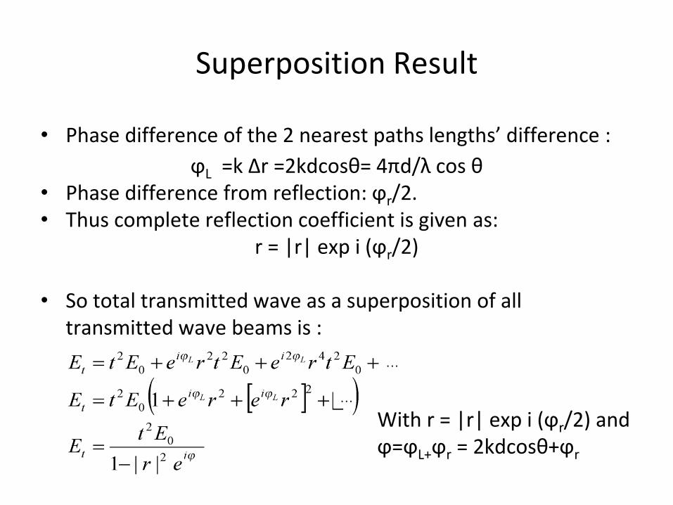
Superposition Result
• Phase difference of the 2 nearest paths lengths’ difference :
ϕL =k Δr =2kdcosθ= 4πd/λ cos θ• Phase difference from reflection: ϕr/2. • Thus complete reflection coefficient is given as:
r = |r| exp i (ϕr/2)
• So total transmitted wave as a superposition of all transmitted wave beams is :
With r = |r| exp i (ϕr/2) and ϕ=ϕL+ϕr = 2kdcosθ+ϕr
…
…
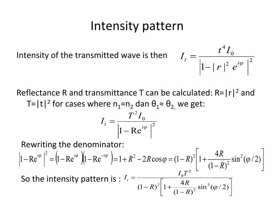
Intensity pattern
Intensity of the transmitted wave is then
Reflectance R and transmittance T can be calculated: R=|r|2 and T=|t|2 for cases where n1=n2 dan θ1≈ θ2, we get:
Rewriting the denominator:
So the intensity pattern is :
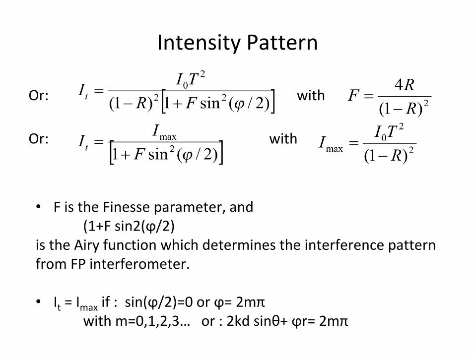
Intensity Pattern
Or: with
Or: with
• F is the Finesse parameter, and (1+F sin2(ϕ/2)
is the Airy function which determines the interference pattern from FP interferometer.
• It = Imax if : sin(ϕ/2)=0 or ϕ= 2mπ with m=0,1,2,3… or : 2kd sinθ+ ϕr= 2mπ
Intensity Pattern
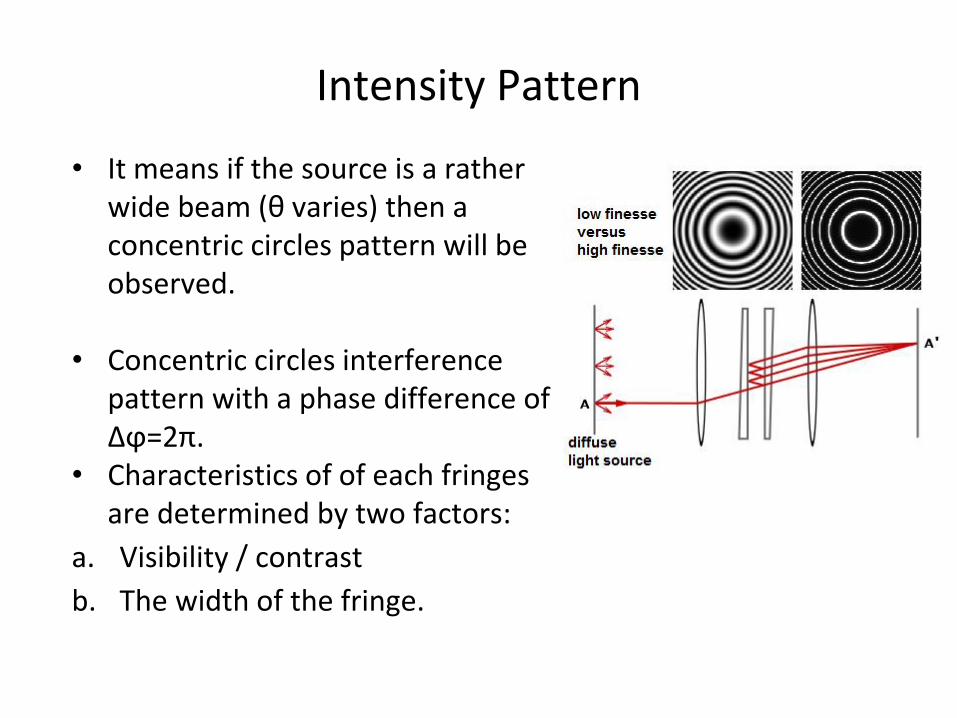
• It means if the source is a rather wide beam (θ varies) then a concentric circles pattern will be observed.
• Concentric circles interference pattern with a phase difference ofΔϕ=2π.
• Characteristics of of each fringes are determined by two factors:
a. Visibility / contrast
b. The width of the fringe.
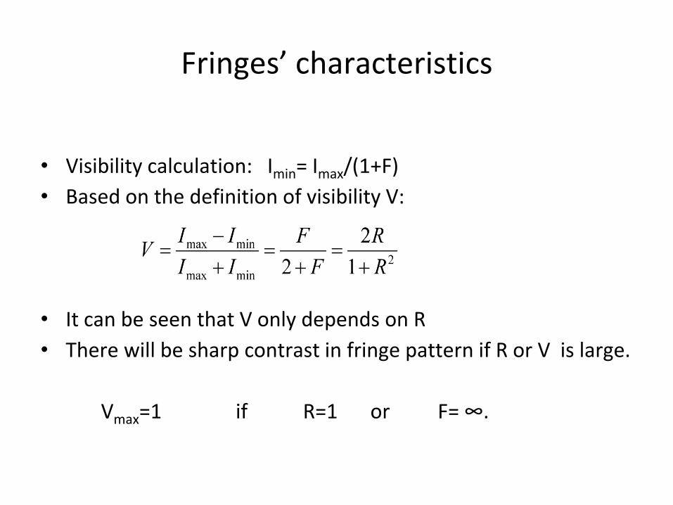
Fringes’ characteristics
• Visibility calculation: Imin= Imax/(1+F)
• Based on the definition of visibility V:
• It can be seen that V only depends on R
• There will be sharp contrast in fringe pattern if R or V is large.
Vmax=1 if R=1 or F= ∞.
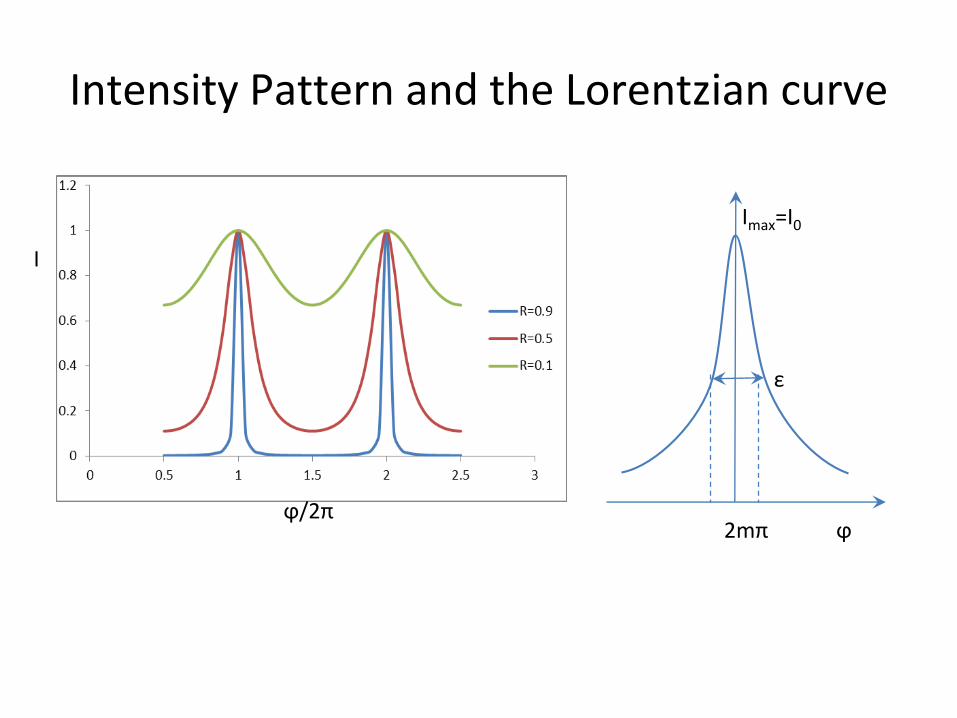
Intensity Pattern and the Lorentzian curve
I
ϕ/2π
Imax=I0
ε
2mπ ϕ
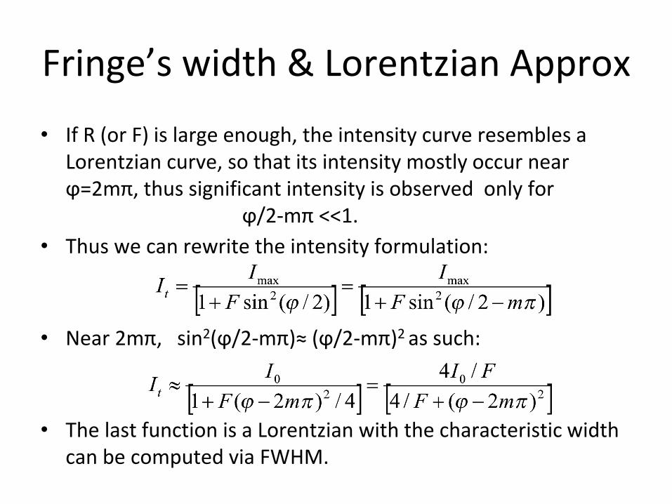
Fringe’s width & Lorentzian Approx
• If R (or F) is large enough, the intensity curve resembles a Lorentzian curve, so that its intensity mostly occur near ϕ=2mπ, thus significant intensity is observed only for
ϕ/2-mπ <<1.
• Thus we can rewrite the intensity formulation:
• Near 2mπ, sin2(ϕ/2-mπ)≈ (ϕ/2-mπ)2 as such:
• The last function is a Lorentzian with the characteristic width can be computed via FWHM.
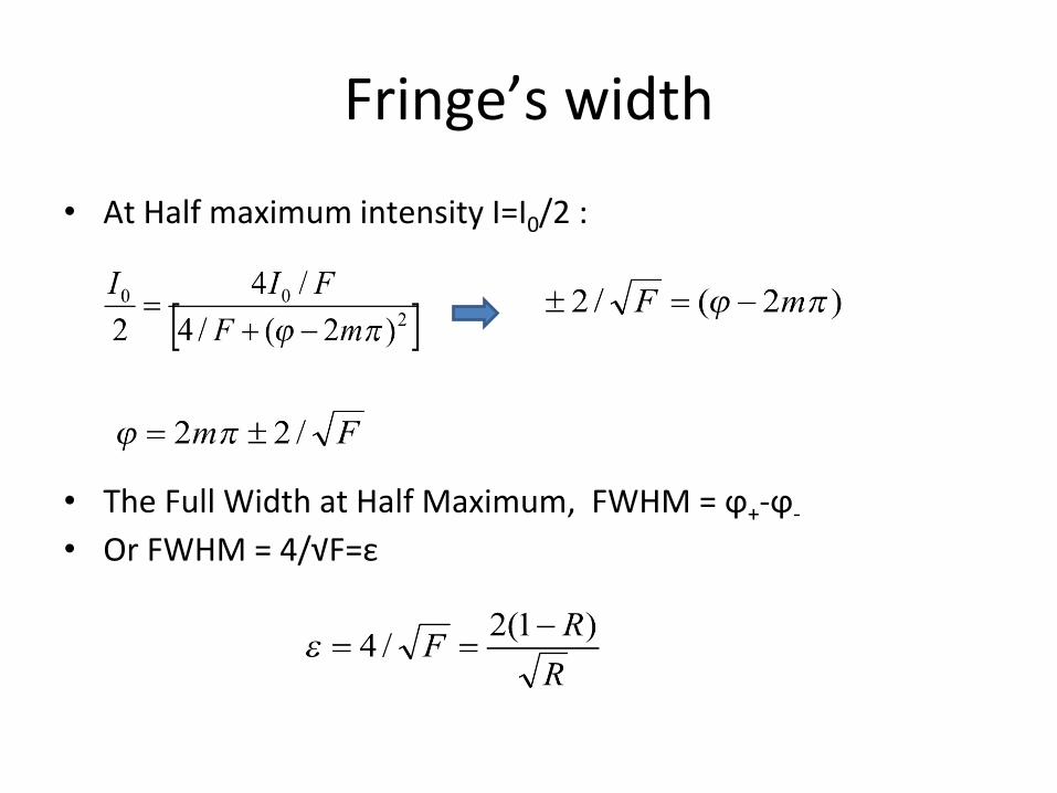
Fringe’s width
• At Half maximum intensity I=I0/2 :
• The Full Width at Half Maximum, FWHM = ϕ+-ϕ-
• Or FWHM = 4/√F=ε
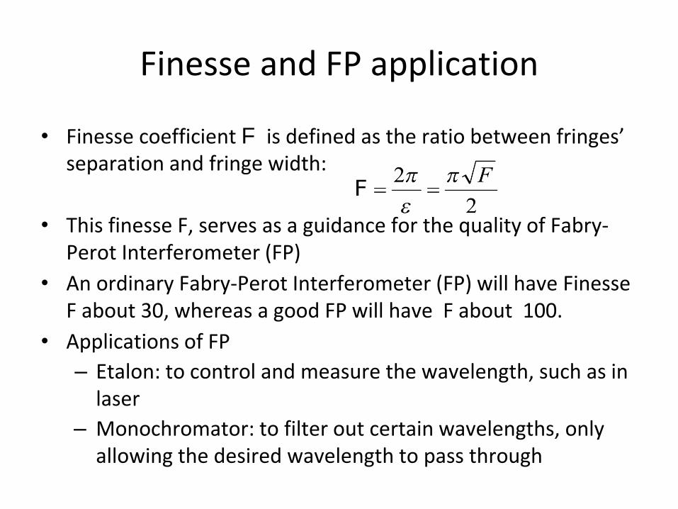
Finesse and FP application
• Finesse coefficient F is defined as the ratio between fringes’ separation and fringe width:
• This finesse F, serves as a guidance for the quality of Fabry-Perot Interferometer (FP)
• An ordinary Fabry-Perot Interferometer (FP) will have Finesse F about 30, whereas a good FP will have F about 100.
• Applications of FP
– Etalon: to control and measure the wavelength, such as in laser
– Monochromator: to filter out certain wavelengths, only allowing the desired wavelength to pass through
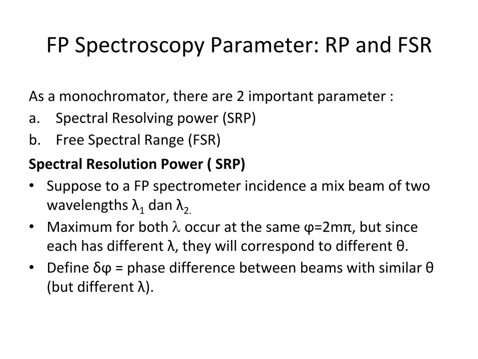
FP Spectroscopy Parameter: RP and FSR
As a monochromator, there are 2 important parameter :
a. Spectral Resolving power (SRP)
b. Free Spectral Range (FSR)
Spectral Resolution Power ( SRP)
• Suppose to a FP spectrometer incidence a mix beam of two wavelengths λ1 dan λ2.
• Maximum for both occur at the same ϕ=2mπ, but since each has different λ, they will correspond to different θ.
• Define δϕ = phase difference between beams with similar θ (but different λ).
FP Spectroscopy Parameter: SRP and FSR
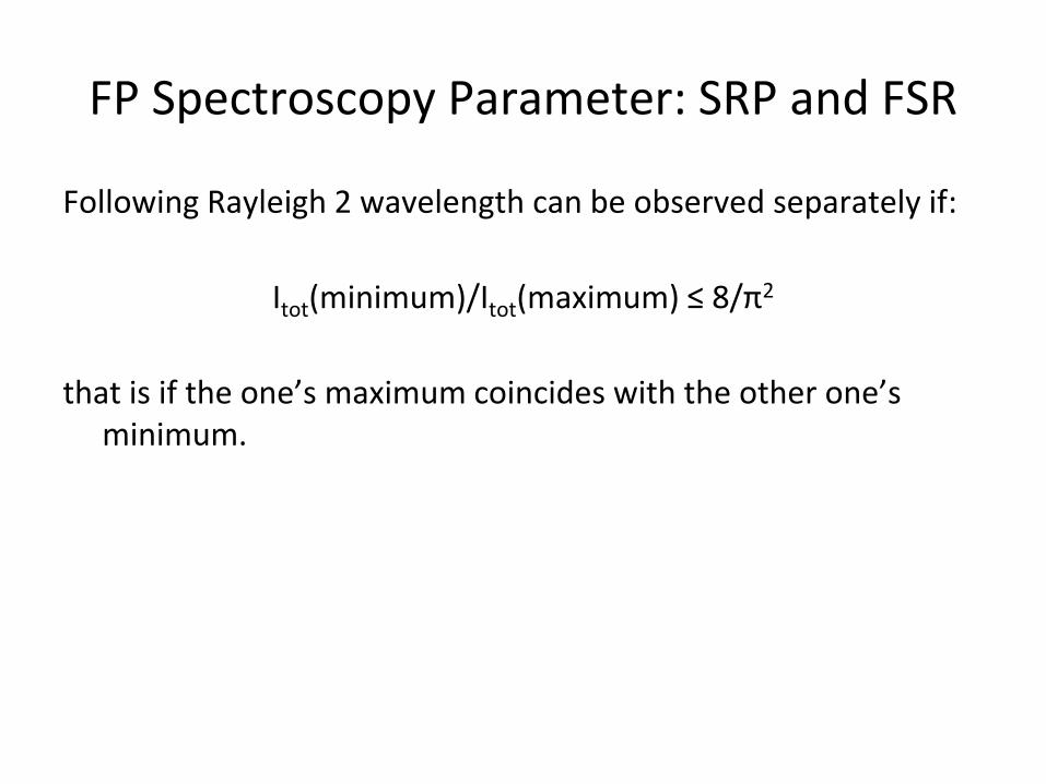
Following Rayleigh 2 wavelength can be observed separately if:
Itot(minimum)/Itot(maximum) ≤ 8/π2
that is if the one’s maximum coincides with the other one’s minimum.
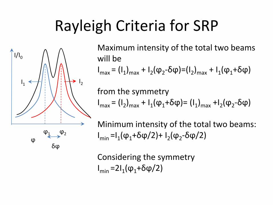
Rayleigh Criteria for SRP
I1
ϕ1 ϕ2
ϕ
I2
I/I0
δϕ
Maximum intensity of the total two beams will beImax = (I1)max + I2(ϕ2-δϕ)=(I2)max + I1(ϕ1+δϕ)
from the symmetryImax = (I2)max + I1(ϕ1+δϕ)= (I1)max +I2(ϕ2-δϕ)
Minimum intensity of the total two beams:Imin =I1(ϕ1+δϕ/2)+ I2(ϕ2-δϕ/2)
Considering the symmetryImin =2I1(ϕ1+δϕ/2)
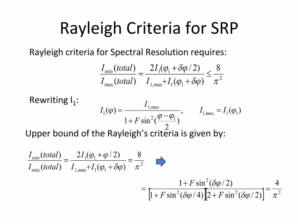
Rayleigh Criteria for SRPRayleigh criteria for Spectral Resolution requires:
Rewriting I1:
Upper bound of the Rayleigh’s criteria is given by:
Rayleigh Criteria for SRP
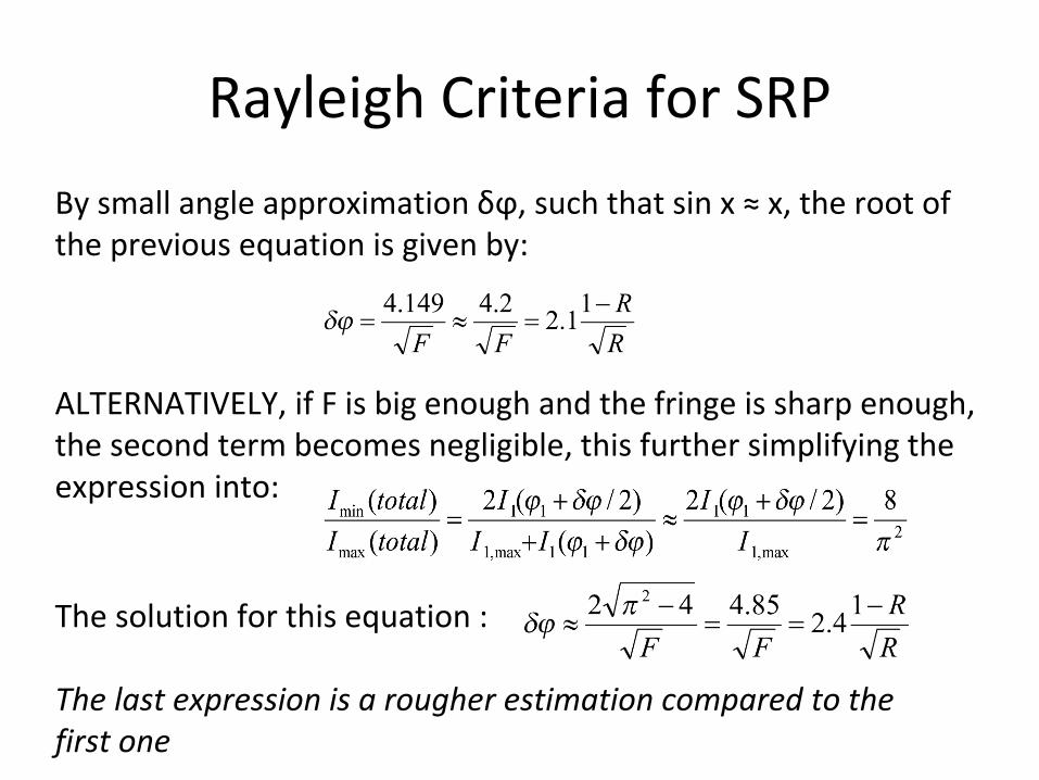
The solution for this equation :
The last expression is a rougher estimation compared to the first one
ALTERNATIVELY, if F is big enough and the fringe is sharp enough, the second term becomes negligible, this further simplifying the expression into:
By small angle approximation δϕ, such that sin x ≈ x, the root of the previous equation is given by:
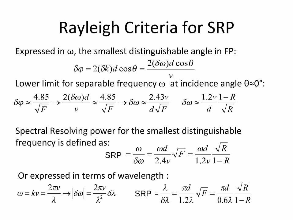
Rayleigh Criteria for SRPExpressed in ω, the smallest distinguishable angle in FP:
Or expressed in terms of wavelength :
Lower limit for separable frequency at incidence angle θ≈0°:
Spectral Resolving power for the smallest distinguishable frequency is defined as:
SRP
SRP
Rayleigh Criteria for SRP
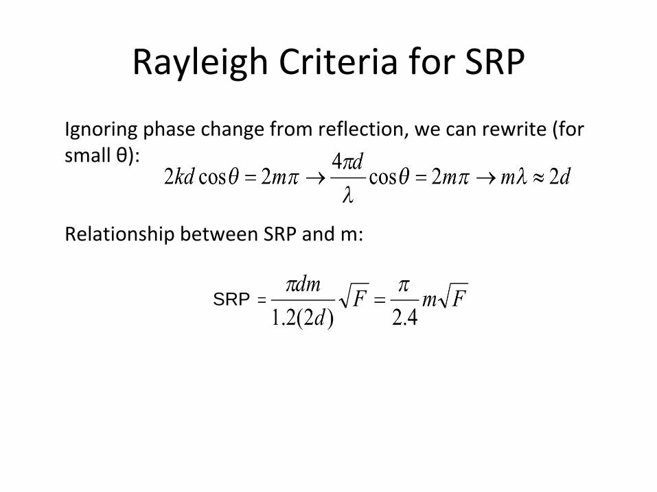
Ignoring phase change from reflection, we can rewrite (for small θ):
Relationship between SRP and m:
SRP
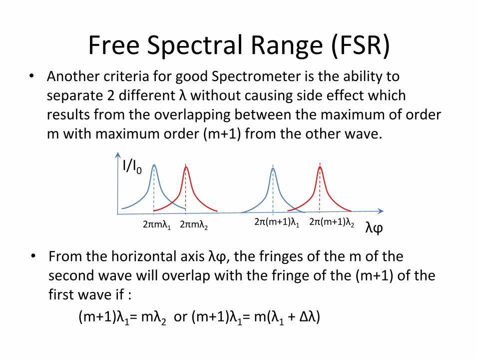
Free Spectral Range (FSR)• Another criteria for good Spectrometer is the ability to
separate 2 different λ without causing side effect which results from the overlapping between the maximum of order m with maximum order (m+1) from the other wave.
2πmλ1 2πmλ2
I/I0
λϕ2π(m+1)λ1 2π(m+1)λ2
• From the horizontal axis λϕ, the fringes of the m of the second wave will overlap with the fringe of the (m+1) of the first wave if :
(m+1)λ1= mλ2 or (m+1)λ1= m(λ1 + Δλ)
Free Spectral Range (FSR)
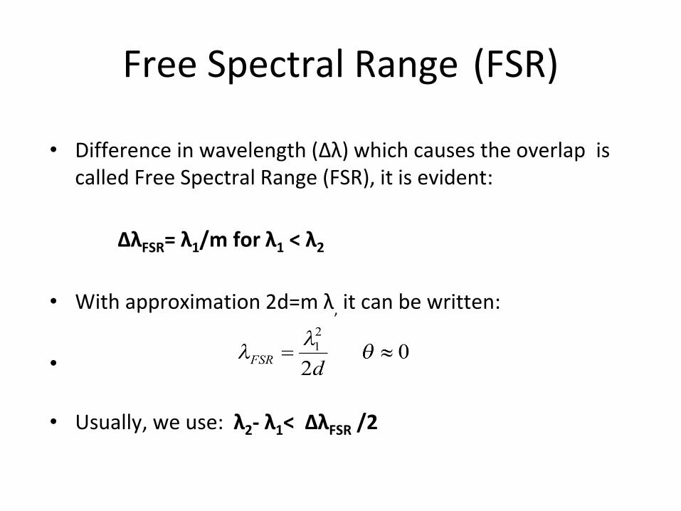
• Difference in wavelength (Δλ) which causes the overlap is called Free Spectral Range (FSR), it is evident:
ΔλFSR= λ1/m for λ1 < λ2
• With approximation 2d=m λ, it can be written:
•
• Usually, we use: λ2- λ1< ΔλFSR /2