
Intelligent Cable Management Systems - BICSI PullingCable Pulling • Watch edggyes of conduit, tray...
26
Intelligent Cable Management Systems Bringing Practical Application Karen Pearson - Leviton
Transcript of Intelligent Cable Management Systems - BICSI PullingCable Pulling • Watch edggyes of conduit, tray...
Intelligent Cable Management Systems
Bringing Practical Application
Karen Pearson - Leviton
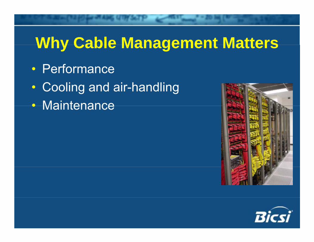
Why Cable Management MattersWhy Cable Management Matters• Performance• Cooling and air-handling• Maintenance• Maintenance
ANSI/TIA 569*ANSI/TIA 569 • Telecommunication Spacesp
– Entrance Facilities (EF)– Equipment Rooms (ER)q p ( )– Telecommunications Rooms (TR)– Telecommunication Enclosures (TE)Telecommunication Enclosures (TE)
• Telecommunications PathwaysCeiling spaces– Ceiling spaces
– Under FloorF it th– Furniture pathways
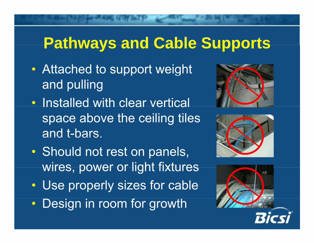
Pathways and Cable SupportsPathways and Cable Supports• Attached to support weight pp g
and pulling• Installed with clear verticalInstalled with clear vertical
space above the ceiling tiles and t-bars.and t bars.
• Should not rest on panels, wires power or light fixtureswires, power or light fixtures
• Use properly sizes for cable• Design in room for growth
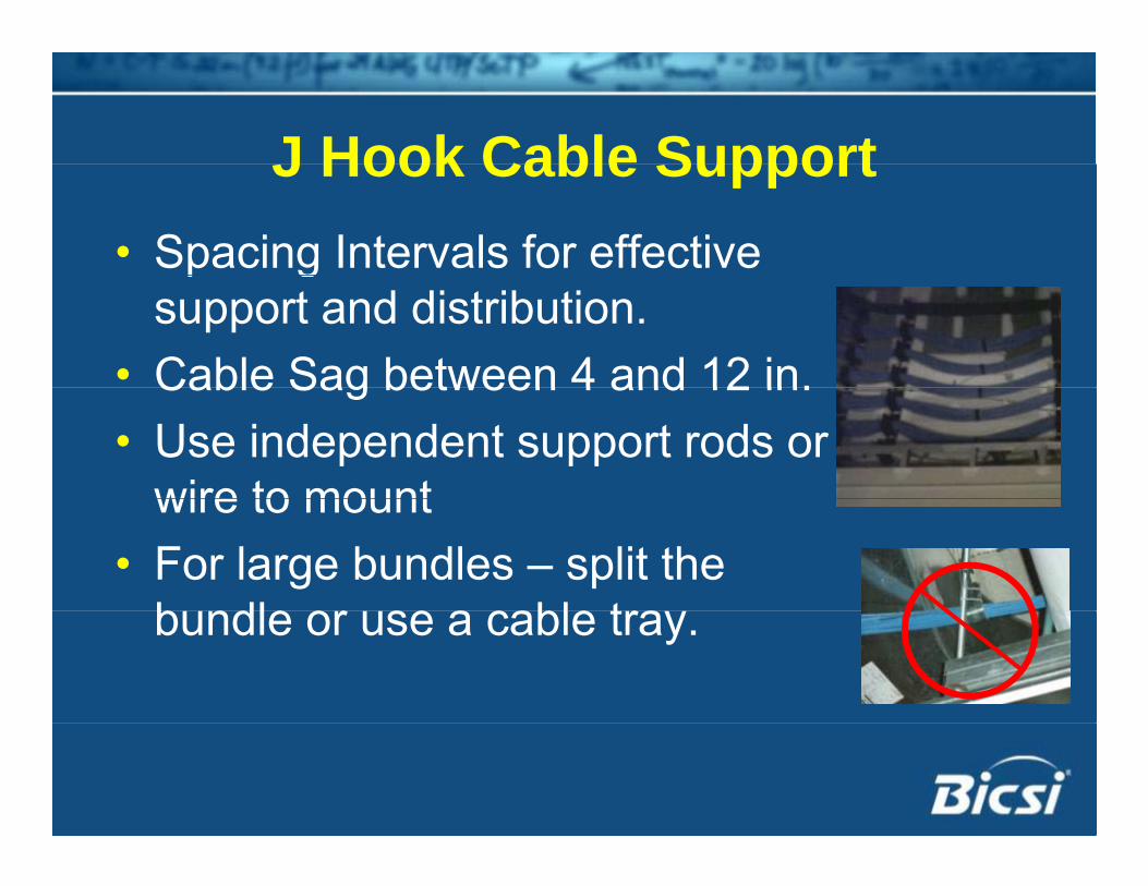
J Hook Cable SupportJ Hook Cable Support• Spacing Intervals for effective p g
support and distribution.• Cable Sag between 4 and 12 in.Cable Sag between 4 and 12 in.• Use independent support rods or
wire to mountwire to mount• For large bundles – split the
b ndle or se a cable trabundle or use a cable tray.
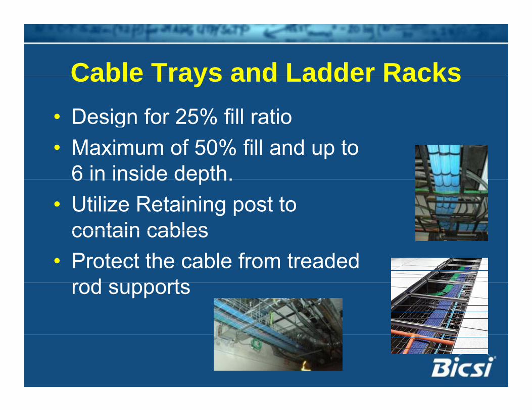
Cable Trays and Ladder RacksCable Trays and Ladder Racks• Design for 25% fill ratiog• Maximum of 50% fill and up to
6 in inside depth.6 in inside depth.• Utilize Retaining post to
contain cablescontain cables• Protect the cable from treaded
rod s pportsrod supports
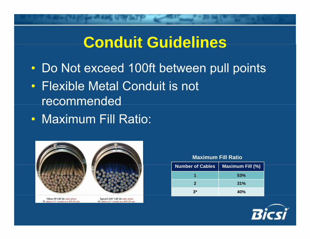
Conduit GuidelinesConduit Guidelines• Do Not exceed 100ft between pull pointsp p• Flexible Metal Conduit is not
recommendedrecommended• Maximum Fill Ratio:
N b f C bl M i Fill (%)
Maximum Fill Ratio Number of Cables Maximum Fill (%)
1 53%
2 31%
3* 40%
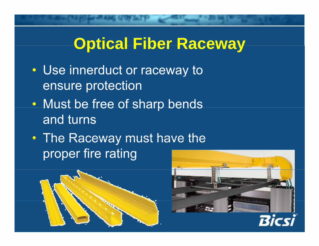
Optical Fiber RacewayOptical Fiber Raceway• Use innerduct or raceway to y
ensure protection• Must be free of sharp bendsMust be free of sharp bends
and turns• The Raceway must have the• The Raceway must have the
proper fire rating
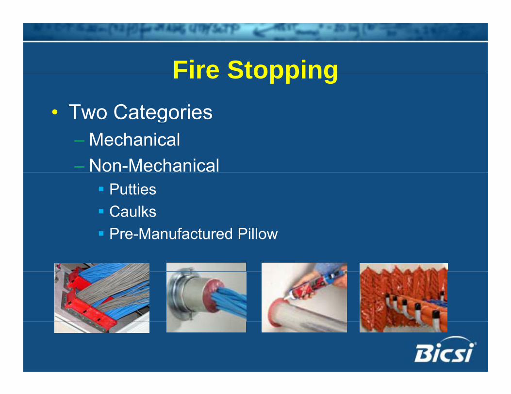
Fire StoppingFire Stopping• Two Categoriesg
– Mechanical – Non-Mechanical Putties Caulks Pre-Manufactured Pillow
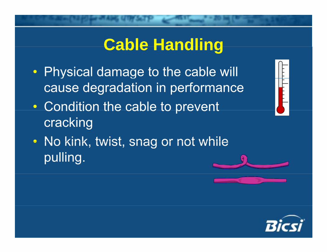
Cable HandlingCable Handling• Physical damage to the cable will y g
cause degradation in performance• Condition the cable to preventCondition the cable to prevent
cracking • No kink twist snag or not while• No kink, twist, snag or not while
pulling.
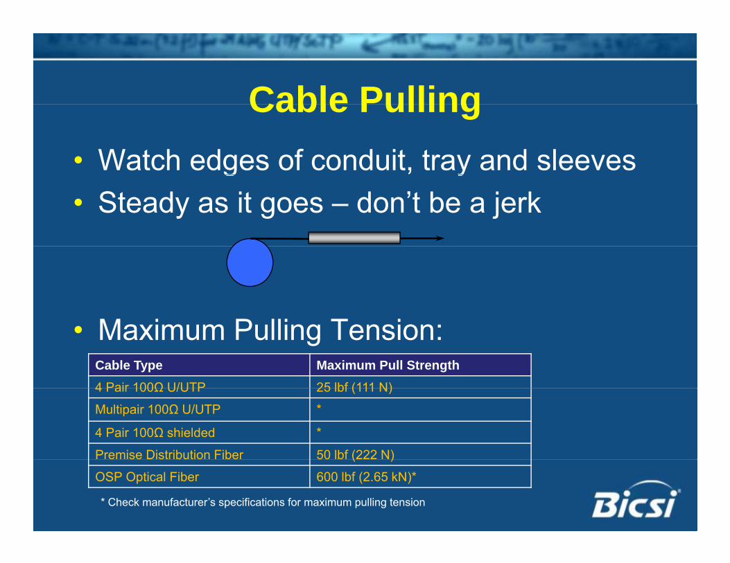
Cable PullingCable Pulling• Watch edges of conduit, tray and sleevesg y• Steady as it goes – don’t be a jerk
• Maximum Pulling Tension:Cable Type Maximum Pull Strength4 Pair 100Ω U/UTP 25 lbf (111 N)4 Pair 100Ω U/UTP 25 lbf (111 N)
Multipair 100Ω U/UTP *
4 Pair 100Ω shielded *
Premise Distribution Fiber 50 lbf (222 N)e se s bu o be 50 b ( )
OSP Optical Fiber 600 lbf (2.65 kN)*
* Check manufacturer’s specifications for maximum pulling tension
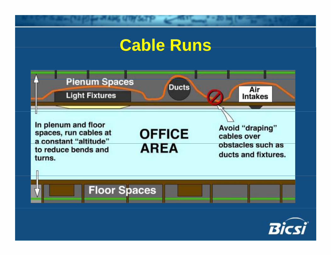
Cable RunsCable Runs
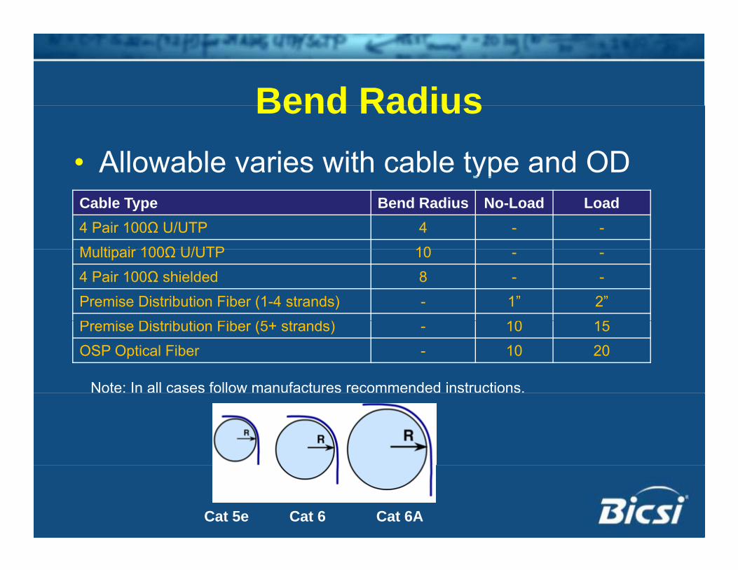
Bend RadiusBend Radius• Allowable varies with cable type and ODypCable Type Bend Radius No-Load Load4 Pair 100Ω U/UTP 4 - -M lti i 100Ω U/UTP 10Multipair 100Ω U/UTP 10 - -4 Pair 100Ω shielded 8 - -Premise Distribution Fiber (1-4 strands) - 1” 2”P i Di t ib ti Fib (5 t d ) 10 15Premise Distribution Fiber (5+ strands) - 10 15OSP Optical Fiber - 10 20
Note: In all cases follow manufactures recommended instructions.
Cat 5e Cat 6 Cat 6A
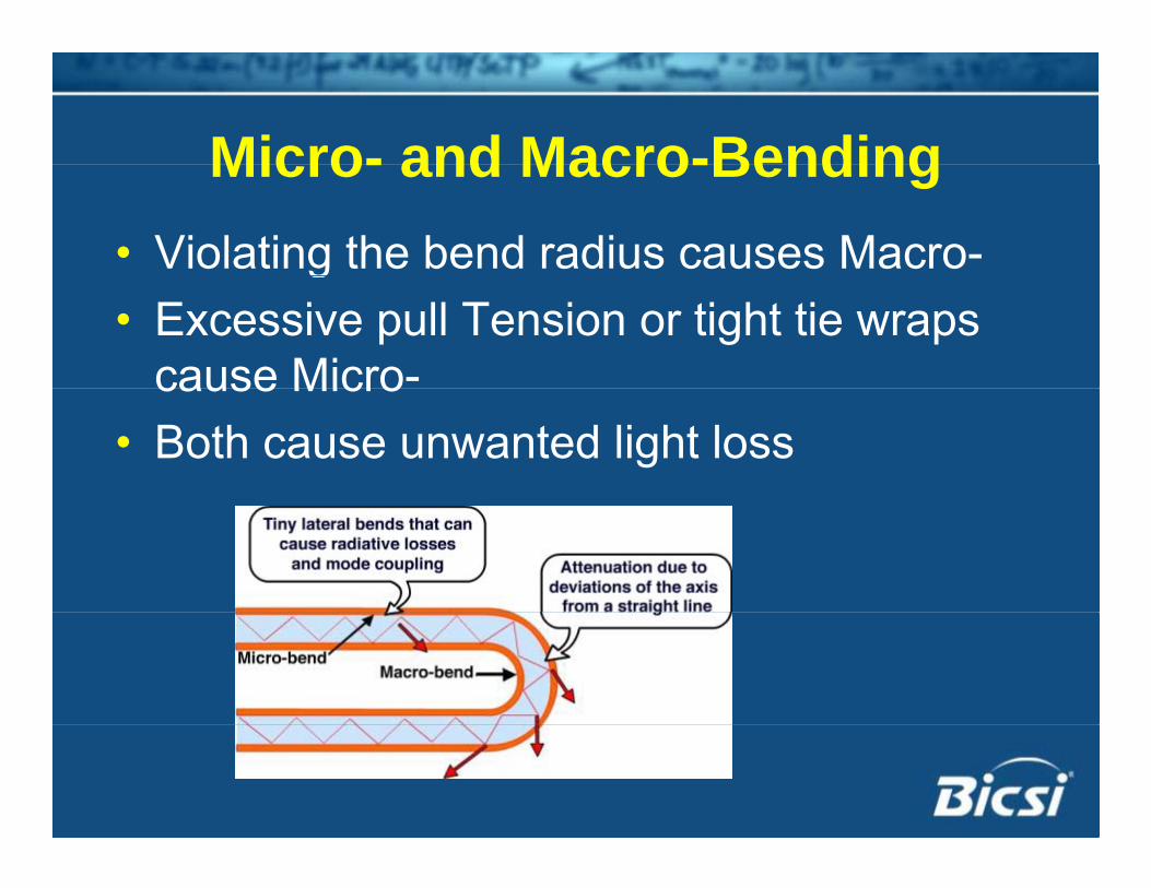
Micro- and Macro-BendingMicro- and Macro-Bending• Violating the bend radius causes Macro-g• Excessive pull Tension or tight tie wraps
cause Micro-cause Micro• Both cause unwanted light loss
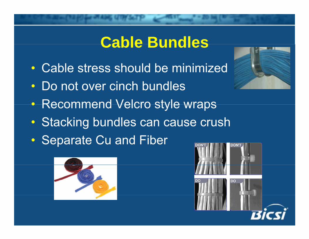
Cable BundlesCable Bundles• Cable stress should be minimized• Do not over cinch bundles• Recommend Velcro style wraps• Recommend Velcro style wraps• Stacking bundles can cause crush• Separate Cu and Fiber
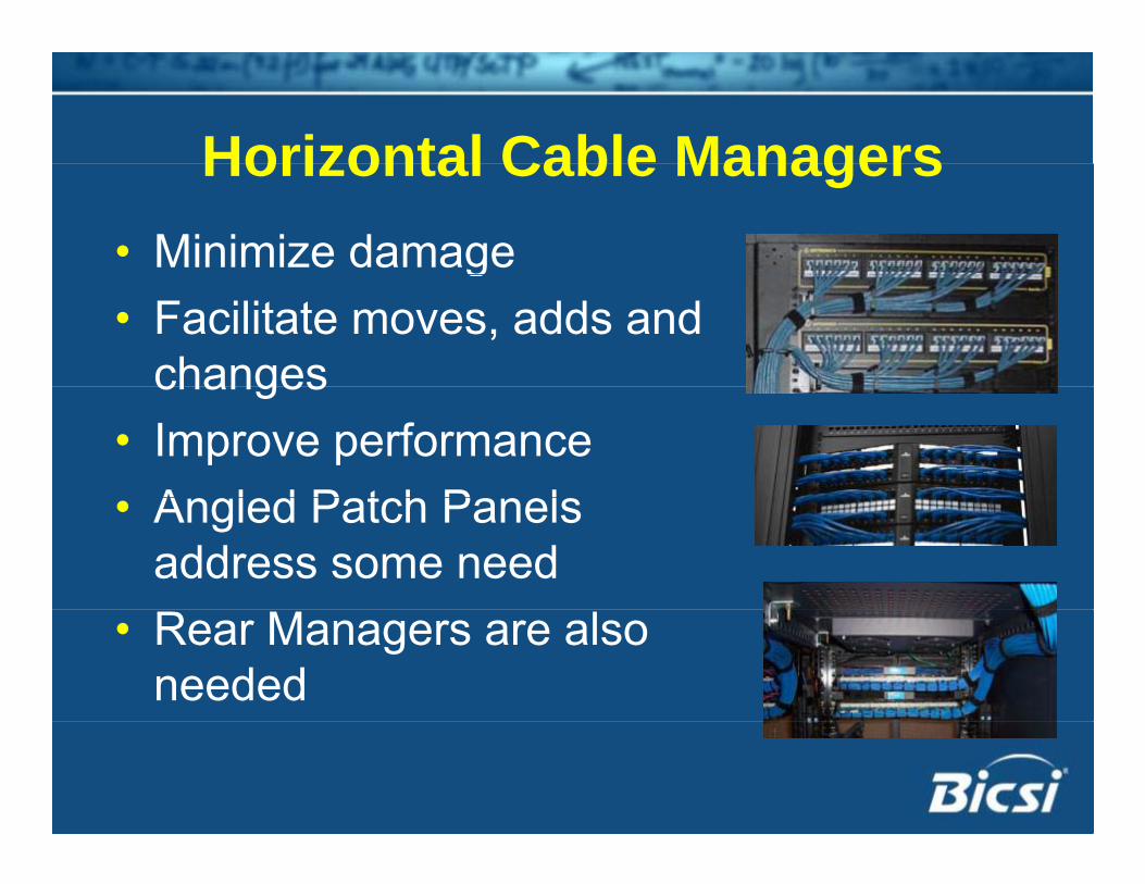
Horizontal Cable ManagersHorizontal Cable Managers• Minimize damageg• Facilitate moves, adds and
changeschanges• Improve performance
A l d P t h P l• Angled Patch Panels address some need
• Rear Managers are also needed
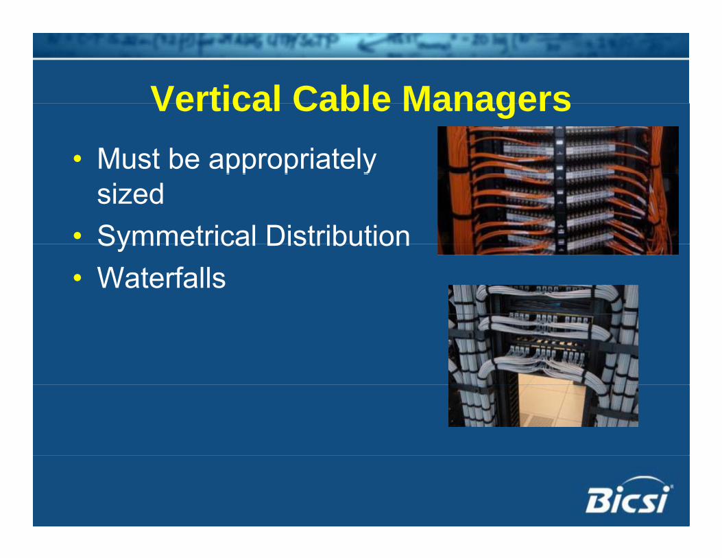
Vertical Cable ManagersVertical Cable Managers• Must be appropriately pp p y
sized• Symmetrical DistributionSymmetrical Distribution • Waterfalls
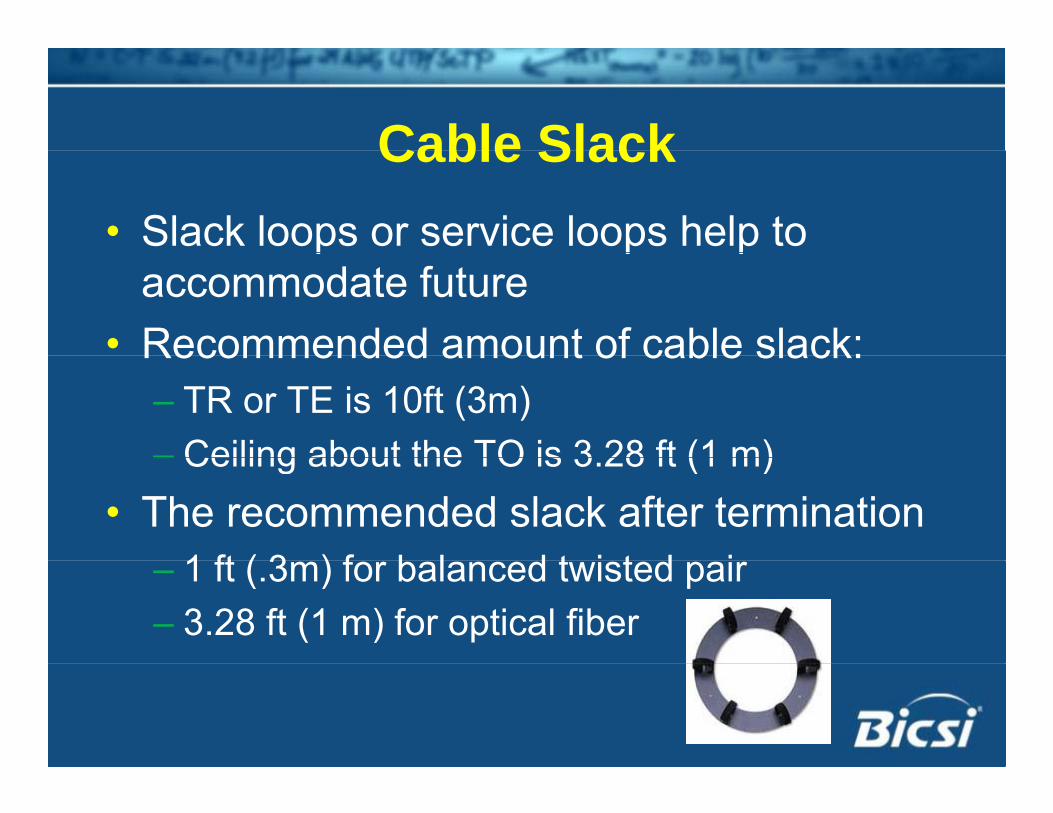
Cable SlackCable Slack• Slack loops or service loops help to p p p
accommodate future• Recommended amount of cable slack:Recommended amount of cable slack:
– TR or TE is 10ft (3m)– Ceiling about the TO is 3 28 ft (1 m)– Ceiling about the TO is 3.28 ft (1 m)
• The recommended slack after termination 1 ft ( 3 ) f b l d t i t d i– 1 ft (.3m) for balanced twisted pair
– 3.28 ft (1 m) for optical fiber
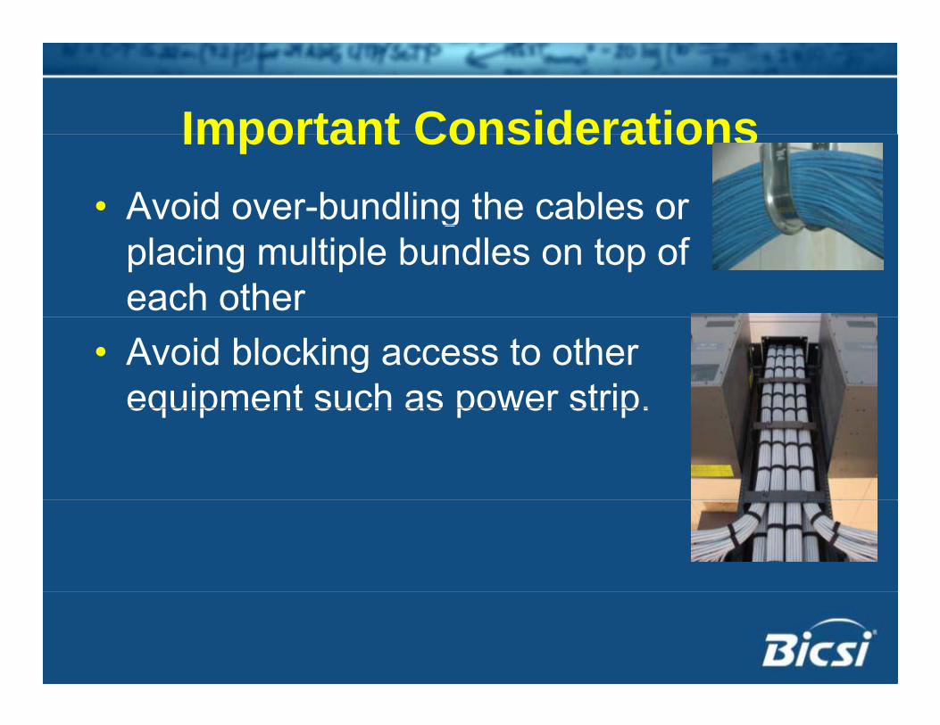
Important ConsiderationsImportant Considerations• Avoid over-bundling the cables or g
placing multiple bundles on top of each other
• Avoid blocking access to other equipment such as power strip.equipment such as power strip.
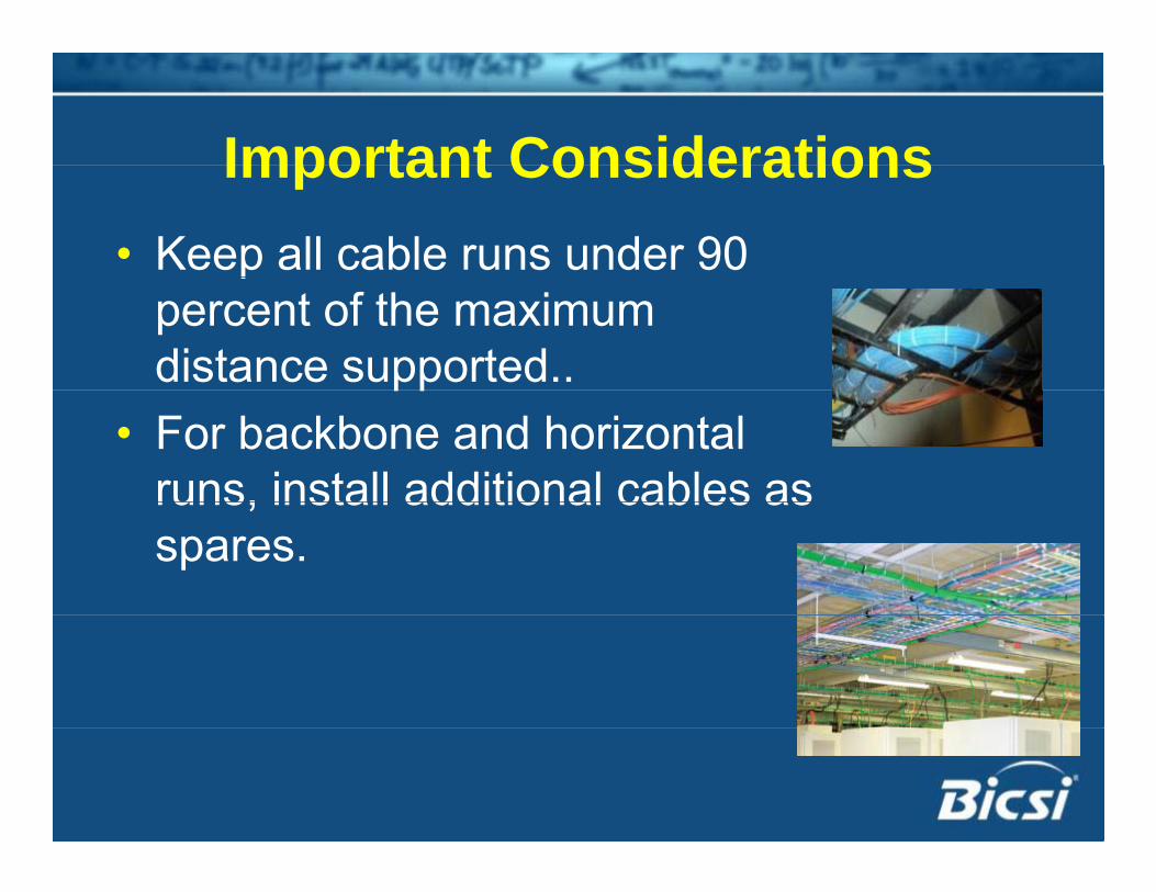
Important ConsiderationsImportant Considerations• Keep all cable runs under 90 p
percent of the maximum distance supported..pp
• For backbone and horizontal runs, install additional cables asruns, install additional cables as spares.
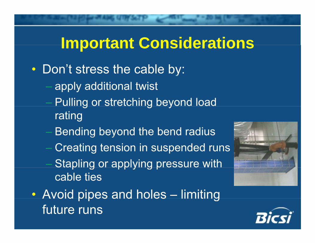
Important ConsiderationsImportant Considerations• Don’t stress the cable by:y
– apply additional twist– Pulling or stretching beyond load g g y
rating– Bending beyond the bend radiusg y– Creating tension in suspended runs– Stapling or applying pressure with p g pp y g p
cable ties• Avoid pipes and holes – limitingAvoid pipes and holes limiting
future runs
Best PracticesBest Practices• Label cables with their destination at every y
termination point• Test every cable as it is installed andTest every cable as it is installed and
terminated.• Do not route cables in the way of fans or• Do not route cables in the way of fans or
air flow
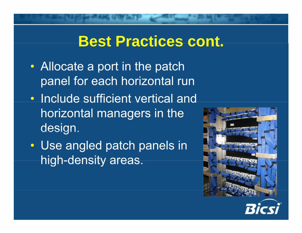
Best Practices contBest Practices cont.• Allocate a port in the patch p p
panel for each horizontal run• Include sufficient vertical andInclude sufficient vertical and
horizontal managers in the design.design.
• Use angled patch panels in high-density areashigh-density areas.
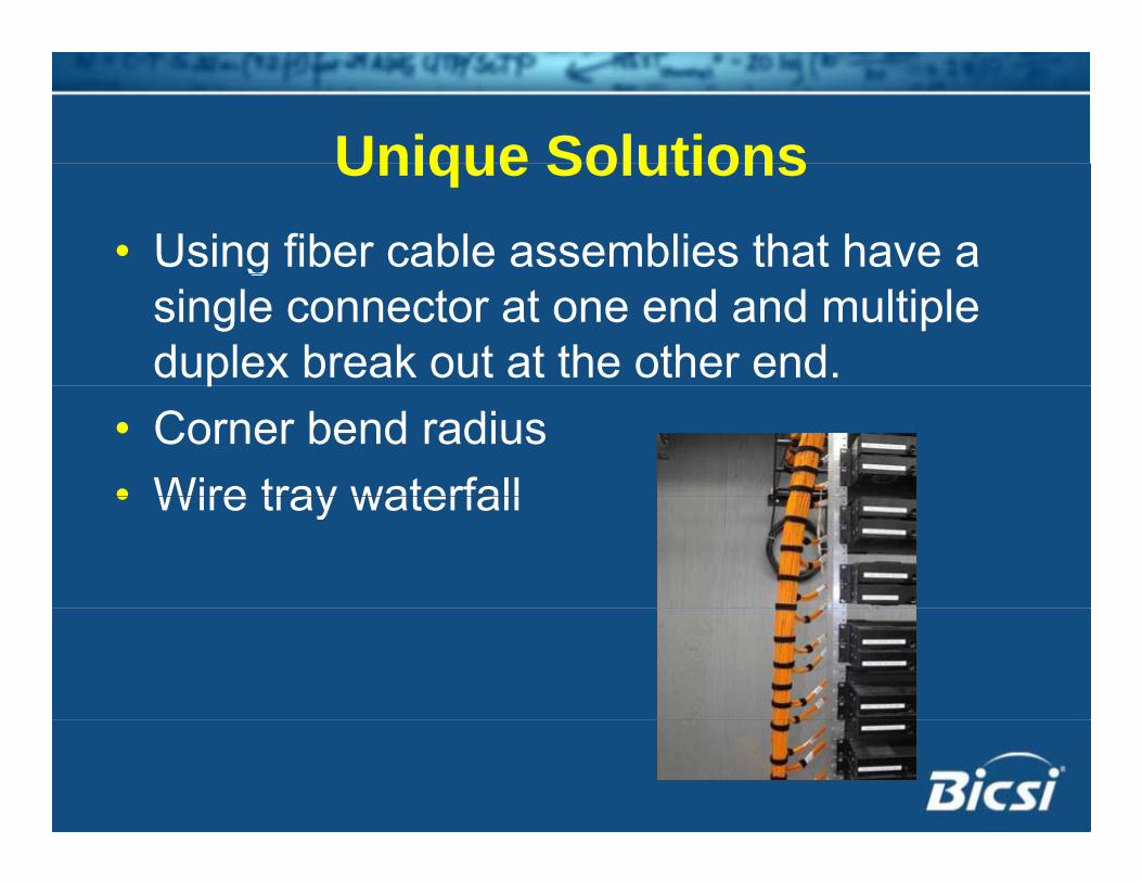
Unique SolutionsUnique Solutions• Using fiber cable assemblies that have a g
single connector at one end and multiple duplex break out at the other end.p
• Corner bend radius• Wire tray waterfall• Wire tray waterfall
SummarySummary• Cabling represents <10% of the overall g p
data center investment• Outlives most of the network componentsOutlives most of the network components• Most difficult to replace
R i tilit f t d f t• Requires versatility for current and future needs
• Since each environment is different, there is no single solution that will meet all your cable management needs.

Thank YouThank You