
Instructions for SAITO FG-21(AAC) 4-Stroke Gasoline · PDF fileInstructions for SAITO...
7
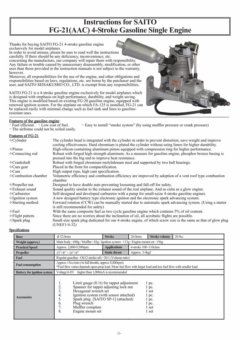
-1- S p ecificatio n s Bore φ32.0mm Stroke 26.0mm Stroke volume 20.9cc Weight (approx.) Main body : 690g / Muffler : 83g / Ignition system : 113g / Engine mount set : 156g Practical Speed Approx. 2,000-9,500rpm Applications 4-stroke 100~110class Propeller 15”×8” ~ 16”×8” Static thrust Approx. 3-4kgf Fuel Regular gasoline : Oil (2-stroke oil) =20:1 (Volume ratio) Fuel consumption Approx 15cc/min (At full throttle, approx 8,800rpm) *Fuel flow varies depends upon prop load. More fuel flow with larger load and less fuel flow with smaller load. Battery for ignition system Voltage:6-8V higher than 1,000mA is recommended Accessories Instructions for SAITO FG-21(AAC) 4-Stroke Gasoline Single Engine Thanks for buying SAITO FG-21 4-stroke gasoline engine exclusively for model airplanes. In order to avoid misuse, please be sure to read well the instructions carefully. If there should be any deficiency, inconvenience, etc. concerning the manufacture, our company will repair them with responsibility. Any failure or trouble caused by unnecessary disassembly, modification, or other uses than those provided in the instruction manuals is not subject to the warranty, however. Moreover, all responsibilities for the use of the engine, and other obligations and responsibilities based on laws, regulations, etc. are borne by the purchaser and the user, and SAITO SEISAKUSHO CO., LTD. is exempt from any responsibilities. SAITO FG-21 is a 4-stroke gasoline engine exclusively for model airplanes which is designed with emphasis on high performance, durability, and weight saving. This engine is modified based on existing FG-20 gasoline engine, equipped with renewed ignition system. For the airplane on which FA-125 is installed, FG-21 can be replaced easily with minimal change such as fuel tank and lines to gasoline- resistant ones. Features of FG-21 Cylinder The cylinder head is integrated with the cylinder in order to prevent distortion, save weight and improve cooling effectiveness. Hard chromium is plated the cylinder without using liners for higher durability. Piston High-silicon-containing aluminum piston equipped with compression ring for higher performance. Connecting rod Robust with forged high-strength aluminum. As a measure for gasoline engine, phosphor bronze busing is pressed into the big end to improve heat resistance. Crankshaft Robust with forged chromium molybdenum steel and supported by two ball bearings. Cam gear Placed in the front for compactification. Cam High output type, high cam specification. Combustion chamber Volumetric efficiency and combustion efficiency are improved by adoption of a vent roof type combustion chamber. Propeller nut Designed to have double nuts preventing loosening and fall-off for safety. Exhaust sound Sound quality similar to the exhaust sound of the real airplane. And as calm as a glow engine. Carburetor Self-designed and developed carburetor with a pump for small-seize 4-stroke gasoline engines. Ignition system A new designed battery type electronic ignition and the electronic spark advancing system. Starting method Forward rotation (CCW) can be manually started due to automatic spark advancing system. (Using a starter is still recommended for safety) Fuel With the same composite fuel as two cycle gasoline engine which contains 5% of oil content. Flight pattern Since there are no worries about the inclination of oil, all acrobatic flights are possible. Spark plug Small-size spark plug dedicated for our 4-stroke engine, of which screw size is the same as that of glow plug (UNEF1/4-32) Features of the gasoline engine ・ Fuel efficient. ・ Low cost of fuel. ・ Easy to install “smoke system” (by using muffler pressure or crank pressure) ・ The airframe could not be soiled easily. 1. Limit gauge (0.1t) for tappet adjustment 1 pc. 2. Spanner for tappet adjusting lock nut 1 pc. 3. Hexagonal wrench set 1 set 4. Ignition system (with sensor attached) 1 pc. 5. Spark plug [SAITO SP-1] (attached) 1 pc. 6. Plug wrench 1 pc. 7. Muffler complete 1 set 8. Engine mount set 1 set
Transcript of Instructions for SAITO FG-21(AAC) 4-Stroke Gasoline · PDF fileInstructions for SAITO...
-1-
SpecificationsBore φ32.0mm Stroke 26.0mm Stroke volume 20.9cc Weight (approx.) Main body : 690g / Muffler : 83g / Ignition system : 113g / Engine mount set : 156g Practical Speed Approx. 2,000-9,500rpm Applications 4-stroke 100~110class Propeller 15”×8” ~ 16”×8” Static thrust Approx. 3-4kgf Fuel Regular gasoline : Oil (2-stroke oil) =20:1 (Volume ratio)
Fuel consumption Approx 15cc/min (At full throttle, approx 8,800rpm) *Fuel flow varies depends upon prop load. More fuel flow with larger load and less fuel flow with smaller load.
Battery for ignition system Voltage:6-8V higher than 1,000mA is recommended
Accessories
Instructions for SAITOFG-21(AAC) 4-Stroke Gasoline Single Engine
Thanks for buying SAITO FG-21 4-stroke gasoline engineexclusively for model airplanes.In order to avoid misuse, please be sure to read well the instructions carefully. If there should be any deficiency, inconvenience, etc.concerning the manufacture, our company will repair them with responsibility. Any failure or trouble caused by unnecessary disassembly, modification, or other uses than those provided in the instruction manuals is not subject to the warranty, however.Moreover, all responsibilities for the use of the engine, and other obligations and responsibilities based on laws, regulations, etc. are borne by the purchaser and the user, and SAITO SEISAKUSHO CO., LTD. is exempt from any responsibilities.
SAITO FG-21 is a 4-stroke gasoline engine exclusively for model airplanes which is designed with emphasis on high performance, durability, and weight saving. This engine is modified based on existing FG-20 gasoline engine, equipped with renewed ignition system. For the airplane on which FA-125 is installed, FG-21 can be replaced easily with minimal change such as fuel tank and lines to gasoline-resistant ones.
Features of FG-21Cylinder The cylinder head is integrated with the cylinder in order to prevent distortion, save weight and improve
cooling effectiveness. Hard chromium is plated the cylinder without using liners for higher durability.Piston High-silicon-containing aluminum piston equipped with compression ring for higher performance.Connecting rod Robust with forged high-strength aluminum. As a measure for gasoline engine, phosphor bronze busing is
pressed into the big end to improve heat resistance.Crankshaft Robust with forged chromium molybdenum steel and supported by two ball bearings.Cam gear Placed in the front for compactification.Cam High output type, high cam specification.Combustion chamber Volumetric efficiency and combustion efficiency are improved by adoption of a vent roof type combustion
chamber.Propeller nut Designed to have double nuts preventing loosening and fall-off for safety.Exhaust sound Sound quality similar to the exhaust sound of the real airplane. And as calm as a glow engine.Carburetor Self-designed and developed carburetor with a pump for small-seize 4-stroke gasoline engines.Ignition system A new designed battery type electronic ignition and the electronic spark advancing system.Starting method Forward rotation (CCW) can be manually started due to automatic spark advancing system. (Using a starter
is still recommended for safety)Fuel With the same composite fuel as two cycle gasoline engine which contains 5% of oil content.Flight pattern Since there are no worries about the inclination of oil, all acrobatic flights are possible.Spark plug Small-size spark plug dedicated for our 4-stroke engine, of which screw size is the same as that of glow plug
(UNEF1/4-32)
Features of the gasoline engine・ Fuel efficient. ・ Low cost of fuel. ・ Easy to install “smoke system” (by using muffler pressure or crank pressure)・ The airframe could not be soiled easily.
1. Limit gauge (0.1t) for tappet adjustment 1 pc.2. Spanner for tappet adjusting lock nut 1 pc.3. Hexagonal wrench set 1 set4. Ignition system (with sensor attached) 1 pc.5. Spark plug [SAITO SP-1] (attached) 1 pc.6. Plug wrench 1 pc.7. Muffler complete 1 set8. Engine mount set 1 set
-2-
Gasoline-proof tube
Filter with weight
Gasoline-proofPump
Outside dimensions
Filter with weight (tank is not included)
Fig.1
Fig.2
43.2
71.8
102.
5
47.3
26.8 25.4
40 76 26.2
179
M8x1.25
405260
63.5 25 13.7
344-Ø4.2
31.5
22
5050
66
6617
33
4-Ø4.2
E.C.
E.C.
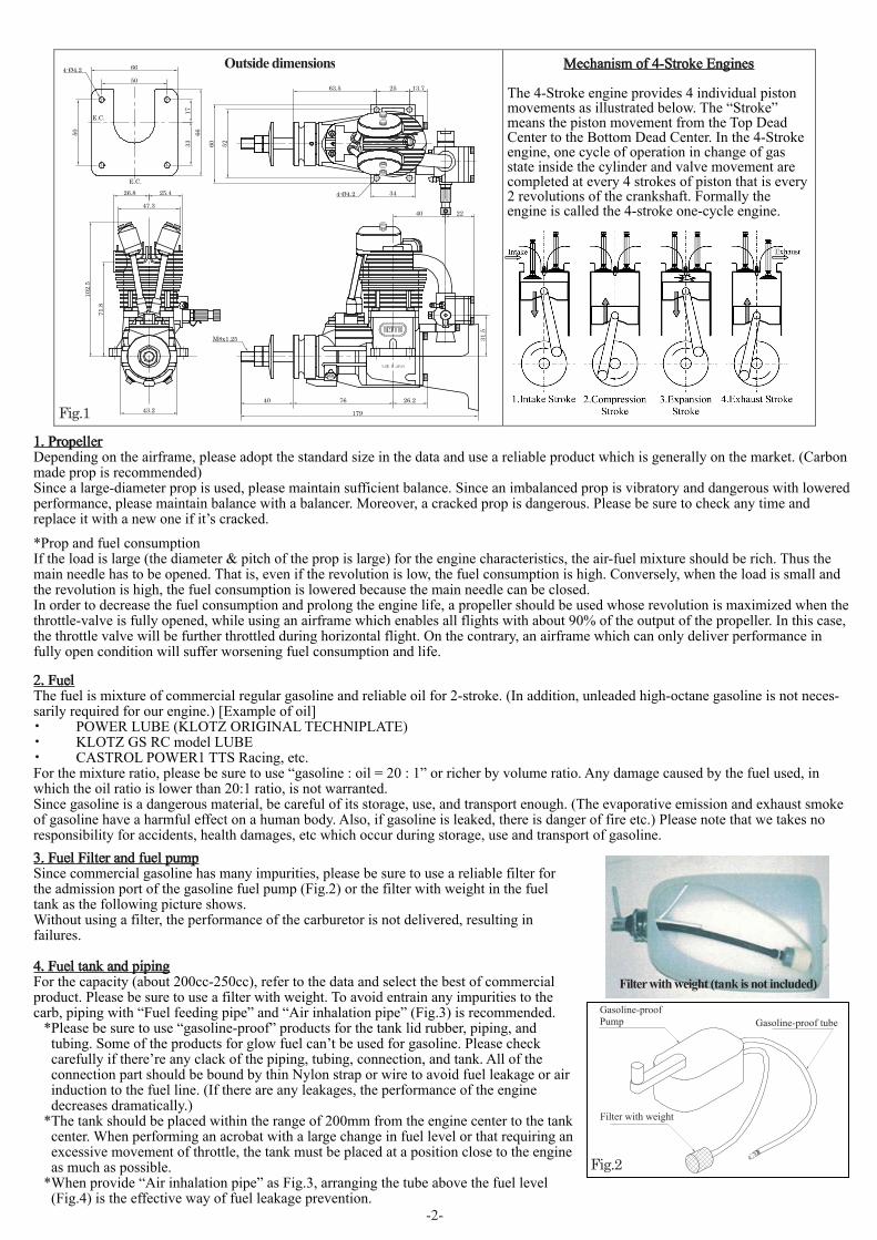
Mechanism of 4-Stroke Engines
The 4-Stroke engine provides 4 individual piston movements as illustrated below. The “Stroke” means the piston movement from the Top Dead Center to the Bottom Dead Center. In the 4-Stroke engine, one cycle of operation in change of gas state inside the cylinder and valve movement are completed at every 4 strokes of piston that is every 2 revolutions of the crankshaft. Formally the engine is called the 4-stroke one-cycle engine.
1. PropellerDepending on the airframe, please adopt the standard size in the data and use a reliable product which is generally on the market. (Carbon made prop is recommended)Since a large-diameter prop is used, please maintain sufficient balance. Since an imbalanced prop is vibratory and dangerous with lowered performance, please maintain balance with a balancer. Moreover, a cracked prop is dangerous. Please be sure to check any time and replace it with a new one if it’s cracked.
*Prop and fuel consumptionIf the load is large (the diameter & pitch of the prop is large) for the engine characteristics, the air-fuel mixture should be rich. Thus the main needle has to be opened. That is, even if the revolution is low, the fuel consumption is high. Conversely, when the load is small and the revolution is high, the fuel consumption is lowered because the main needle can be closed. In order to decrease the fuel consumption and prolong the engine life, a propeller should be used whose revolution is maximized when the throttle-valve is fully opened, while using an airframe which enables all flights with about 90% of the output of the propeller. In this case, the throttle valve will be further throttled during horizontal flight. On the contrary, an airframe which can only deliver performance in fully open condition will suffer worsening fuel consumption and life.
2. FuelThe fuel is mixture of commercial regular gasoline and reliable oil for 2-stroke. (In addition, unleaded high-octane gasoline is not neces-sarily required for our engine.) [Example of oil]・ POWER LUBE (KLOTZ ORIGINAL TECHNIPLATE)・ KLOTZ GS RC model LUBE・ CASTROL POWER1 TTS Racing, etc.For the mixture ratio, please be sure to use “gasoline : oil = 20 : 1” or richer by volume ratio. Any damage caused by the fuel used, in which the oil ratio is lower than 20:1 ratio, is not warranted.Since gasoline is a dangerous material, be careful of its storage, use, and transport enough. (The evaporative emission and exhaust smoke of gasoline have a harmful effect on a human body. Also, if gasoline is leaked, there is danger of fire etc.) Please note that we takes no responsibility for accidents, health damages, etc which occur during storage, use and transport of gasoline.3. Fuel Filter and fuel pumpSince commercial gasoline has many impurities, please be sure to use a reliable filter for the admission port of the gasoline fuel pump (Fig.2) or the filter with weight in the fuel tank as the following picture shows.Without using a filter, the performance of the carburetor is not delivered, resulting in failures.
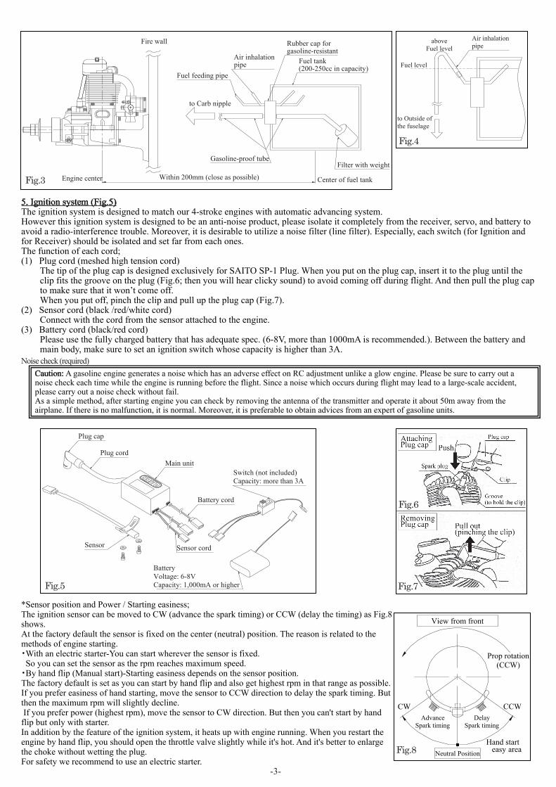
4. Fuel tank and pipingFor the capacity (about 200cc-250cc), refer to the data and select the best of commercial product. Please be sure to use a filter with weight. To avoid entrain any impurities to the carb, piping with “Fuel feeding pipe” and “Air inhalation pipe” (Fig.3) is recommended.
*Please be sure to use “gasoline-proof” products for the tank lid rubber, piping, and tubing. Some of the products for glow fuel can’t be used for gasoline. Please check carefully if there’re any clack of the piping, tubing, connection, and tank. All of the connection part should be bound by thin Nylon strap or wire to avoid fuel leakage or air induction to the fuel line. (If there are any leakages, the performance of the engine decreases dramatically.)
*The tank should be placed within the range of 200mm from the engine center to the tank center. When performing an acrobat with a large change in fuel level or that requiring an excessive movement of throttle, the tank must be placed at a position close to the engine as much as possible.
*When provide “Air inhalation pipe” as Fig.3, arranging the tube above the fuel level (Fig.4) is the effective way of fuel leakage prevention.
-3-
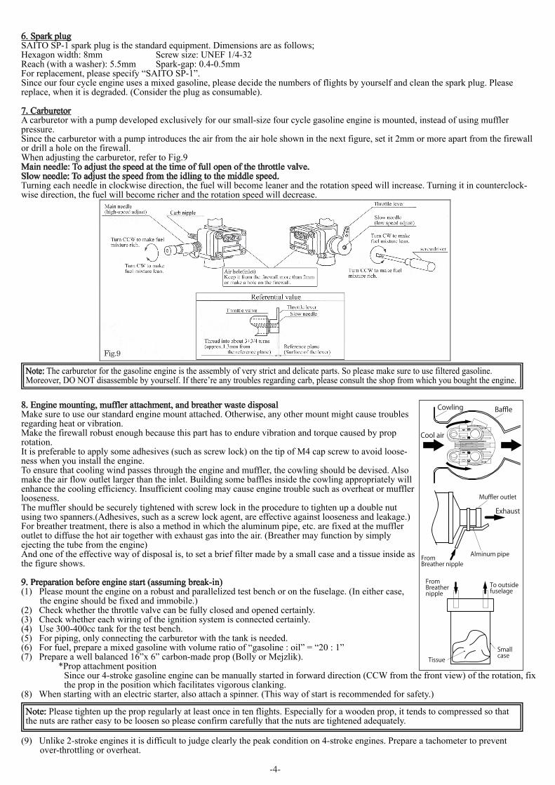
Plug cap
Switch (not included)Capacity: more than 3A
Sensor Sensor cord
BatteryVoltage: 6-8VCapacity: 1,000mA or higher
Plug cordMain unit
Battery cord
Noise check (required)
Fig.5
Fuel level
aboveFuel level
to Outside ofthe fuselage
Air inhalationpipe
Fig.4
Fig.3 Center of fuel tankWithin 200mm (close as possible)
Fire wall
Engine center
Fuel tank(200-250cc in capacity)
Gasoline-proof tubeFilter with weight
Air inhalationpipe
Fuel feeding pipe
to Carb nipple
Rubber cap forgasoline-resistant
Fig.8
Fig.6
Fig.7
5. Ignition system (Fig.5)The ignition system is designed to match our 4-stroke engines with automatic advancing system.However this ignition system is designed to be an anti-noise product, please isolate it completely from the receiver, servo, and battery to avoid a radio-interference trouble. Moreover, it is desirable to utilize a noise filter (line filter). Especially, each switch (for Ignition and for Receiver) should be isolated and set far from each ones.The function of each cord;(1) Plug cord (meshed high tension cord)
The tip of the plug cap is designed exclusively for SAITO SP-1 Plug. When you put on the plug cap, insert it to the plug until the clip fits the groove on the plug (Fig.6; then you will hear clicky sound) to avoid coming off during flight. And then pull the plug cap to make sure that it won’t come off.When you put off, pinch the clip and pull up the plug cap (Fig.7).
(2) Sensor cord (black /red/white cord) Connect with the cord from the sensor attached to the engine.
(3) Battery cord (black/red cord)Please use the fully charged battery that has adequate spec. (6-8V, more than 1000mA is recommended.). Between the battery and main body, make sure to set an ignition switch whose capacity is higher than 3A.
Caution: A gasoline engine generates a noise which has an adverse effect on RC adjustment unlike a glow engine. Please be sure to carry out a noise check each time while the engine is running before the flight. Since a noise which occurs during flight may lead to a large-scale accident, please carry out a noise check without fail. As a simple method, after starting engine you can check by removing the antenna of the transmitter and operate it about 50m away from the airplane. If there is no malfunction, it is normal. Moreover, it is preferable to obtain advices from an expert of gasoline units.
*Sensor position and Power / Starting easiness;The ignition sensor can be moved to CW (advance the spark timing) or CCW (delay the timing) as Fig.8 shows. At the factory default the sensor is fixed on the center (neutral) position. The reason is related to the methods of engine starting.・With an electric starter-You can start wherever the sensor is fixed. So you can set the sensor as the rpm reaches maximum speed.・By hand flip (Manual start)-Starting easiness depends on the sensor position.The factory default is set as you can start by hand flip and also get highest rpm in that range as possible.If you prefer easiness of hand starting, move the sensor to CCW direction to delay the spark timing. But then the maximum rpm will slightly decline. If you prefer power (highest rpm), move the sensor to CW direction. But then you can't start by hand flip but only with starter.In addition by the feature of the ignition system, it heats up with engine running. When you restart the engine by hand flip, you should open the throttle valve slightly while it's hot. And it's better to enlarge the choke without wetting the plug.For safety we recommend to use an electric starter.
Neutral PositionHand start
easy area
DelaySpark timing
AdvanceSpark timing
CCWCW
Prop rotation(CCW)
View from front
-4-
Fig.9
6. Spark plugSAITO SP-1 spark plug is the standard equipment. Dimensions are as follows;Hexagon width: 8mm Screw size: UNEF 1/4-32Reach (with a washer): 5.5mm Spark-gap: 0.4-0.5mmFor replacement, please specify “SAITO SP-1”.Since our four cycle engine uses a mixed gasoline, please decide the numbers of flights by yourself and clean the spark plug. Please replace, when it is degraded. (Consider the plug as consumable).
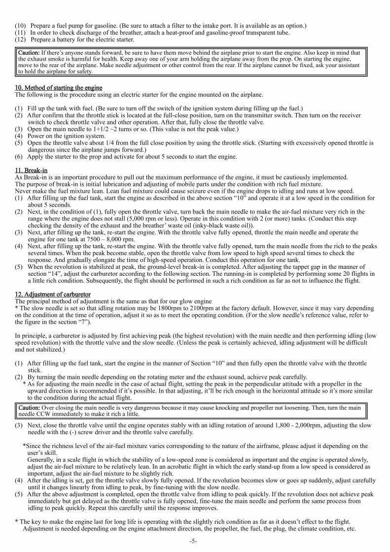
7. CarburetorA carburetor with a pump developed exclusively for our small-size four cycle gasoline engine is mounted, instead of using muffler pressure.Since the carburetor with a pump introduces the air from the air hole shown in the next figure, set it 2mm or more apart from the firewall or drill a hole on the firewall.When adjusting the carburetor, refer to Fig.9Main needle: To adjust the speed at the time of full open of the throttle valve.Slow needle: To adjust the speed from the idling to the middle speed. Turning each needle in clockwise direction, the fuel will become leaner and the rotation speed will increase. Turning it in counterclock-wise direction, the fuel will become richer and the rotation speed will decrease.
Note: The carburetor for the gasoline engine is the assembly of very strict and delicate parts. So please make sure to use filtered gasoline. Moreover, DO NOT disassemble by yourself. If there’re any troubles regarding carb, please consult the shop from which you bought the engine.
Note: Please tighten up the prop regularly at least once in ten flights. Especially for a wooden prop, it tends to compressed so that the nuts are rather easy to be loosen so please confirm carefully that the nuts are tightened adequately.
8. Engine mounting, muffler attachment, and breather waste disposalMake sure to use our standard engine mount attached. Otherwise, any other mount might cause troubles regarding heat or vibration.Make the firewall robust enough because this part has to endure vibration and torque caused by prop rotation.It is preferable to apply some adhesives (such as screw lock) on the tip of M4 cap screw to avoid loose-ness when you install the engine.To ensure that cooling wind passes through the engine and muffler, the cowling should be devised. Also make the air flow outlet larger than the inlet. Building some baffles inside the cowling appropriately will enhance the cooling efficiency. Insufficient cooling may cause engine trouble such as overheat or muffler looseness.The muffler should be securely tightened with screw lock in the procedure to tighten up a double nut using two spanners.(Adhesives, such as a screw lock agent, are effective against looseness and leakage.)For breather treatment, there is also a method in which the aluminum pipe, etc. are fixed at the muffler outlet to diffuse the hot air together with exhaust gas into the air. (Breather may function by simply ejecting the tube from the engine)And one of the effective way of disposal is, to set a brief filter made by a small case and a tissue inside as the figure shows.
9. Preparation before engine start (assuming break-in)(1) Please mount the engine on a robust and parallelized test bench or on the fuselage. (In either case,
the engine should be fixed and immobile.)(2) Check whether the throttle valve can be fully closed and opened certainly.(3) Check whether each wiring of the ignition system is connected certainly.(4) Use 300-400cc tank for the test bench.(5) For piping, only connecting the carburetor with the tank is needed.(6) For fuel, prepare a mixed gasoline with volume ratio of “gasoline : oil” = “20 : 1”(7) Prepare a well balanced 16”x 6” carbon-made prop (Bolly or Mejzlik).
*Prop attachment positionSince our 4-stroke gasoline engine can be manually started in forward direction (CCW from the front view) of the rotation, fix the prop in the position which facilitates vigorous clanking.
(8) When starting with an electric starter, also attach a spinner. (This way of start is recommended for safety.)
(9) Unlike 2-stroke engines it is difficult to judge clearly the peak condition on 4-stroke engines. Prepare a tachometer to prevent over-throttling or overheat.
BaffleCowling
Cool air
FromBreather nipple
Exhaust
Muffler outlet
Alminum pipe
FromBreathernipple
Tissue
Smallcase
To outsidefuselage
-5-
(10) Prepare a fuel pump for gasoline. (Be sure to attach a filter to the intake port. It is available as an option.)(11) In order to check discharge of the breather, attach a heat-proof and gasoline-proof transparent tube.(12) Prepare a battery for the electric starter.
10. Method of starting the engineThe following is the procedure using an electric starter for the engine mounted on the airplane.
(1) Fill up the tank with fuel. (Be sure to turn off the switch of the ignition system during filling up the fuel.)(2) After confirm that the throttle stick is located at the full-close position, turn on the transmitter switch. Then turn on the receiver
switch to check throttle valve and other operation. After that, fully close the throttle valve.(3) Open the main needle to 1+1/2 ~2 turns or so. (This value is not the peak value.)(4) Power on the ignition system.(5) Open the throttle valve about 1/4 from the full close position by using the throttle stick. (Starting with excessively opened throttle is
dangerous since the airplane jumps forward.)(6) Apply the starter to the prop and activate for about 5 seconds to start the engine.
11. Break-inAs Break-in is an important procedure to pull out the maximum performance of the engine, it must be cautiously implemented.The purpose of break-in is initial lubrication and adjusting of mobile parts under the condition with rich fuel mixture.Never make the fuel mixture lean. Lean fuel mixture could cause seizure even if the engine drops to idling and runs at low speed.(1) After filling up the fuel tank, start the engine as described in the above section “10” and operate it at a low speed in the condition for
about 5 seconds.(2) Next, in the condition of (1), fully open the throttle valve, turn back the main needle to make the air-fuel mixture very rich in the
range where the engine does not stall (5,000 rpm or less). Operate in this condition with 2 (or more) tanks. (Conduct this step checking the density of the exhaust and the breather’ waste oil (inky-black waste oil)).
(3) Next, after filling up the tank, re-start the engine. With the throttle valve fully opened, throttle the main needle and operate the engine for one tank at 7500 – 8,000 rpm.
(4) Next, after filling up the tank, re-start the engine. With the throttle valve fully opened, turn the main needle from the rich to the peaks several times. When the peak become stable, open the throttle valve from low speed to high speed several times to check the response. And gradually elongate the time of high-speed operation. Conduct this operation for one tank.
(5) When the revolution is stabilized at peak, the ground-level break-in is completed. After adjusting the tappet gap in the manner of section “14”, adjust the carburetor according to the following section. The running-in is completed by performing some 20 flights in a little rich condition. Subsequently, the flight should be performed in such a rich condition as far as not to influence the flight.
12. Adjustment of carburetorThe principal method of adjustment is the same as that for our glow engine* The slow needle is set so that idling rotation may be 1800rpm to 2100rpm at the factory default. However, since it may vary depending on the condition at the time of operation, adjust it so as to meet the operating condition. (For the slow needle’s reference value, refer to the figure in the section “7”).
In principle, a carburetor is adjusted by first achieving peak (the highest revolution) with the main needle and then performing idling (low speed revolution) with the throttle valve and the slow needle. (Unless the peak is certainly achieved, idling adjustment will be difficult and not stabilized.)
(1) After filling up the fuel tank, start the engine in the manner of Section “10” and then fully open the throttle valve with the throttle stick.
(2) By turning the main needle depending on the rotating meter and the exhaust sound, achieve peak carefully.* As for adjusting the main needle in the case of actual flight, setting the peak in the perpendicular attitude with a propeller in the
upward direction is recommended if it’s possible. In that adjusting, it’ll be rich enough in the horizontal attitude so it’s more similar to the condition during the actual flight.
(3) Next, close the throttle valve until the engine operates stably with an idling rotation of around 1,800 - 2,000rpm, adjusting the slow needle with the (-) screw driver and the throttle valve carefully.
*Since the richness level of the air-fuel mixture varies corresponding to the nature of the airframe, please adjust it depending on the user’s skill.Generally, in a scale flight in which the stability of a low-speed zone is considered as important and the engine is operated slowly, adjust the air-fuel mixture to be relatively lean. In an acrobatic flight in which the early stand-up from a low speed is considered as important, adjust the air-fuel mixture to be slightly rich.
(4) After the idling is set, get the throttle valve slowly fully opened. If the revolution becomes slow or goes up suddenly, adjust carefully until it changes linearly from idling to peak, by fine-tuning with the slow needle.
(5) After the above adjustment is completed, open the throttle valve from idling to peak quickly. If the revolution does not achieve peak immediately but get delayed as the throttle valve is fully opened, fine-tune the main needle and perform the same process from idling to peak quickly. Repeat this carefully until the response improves.
* The key to make the engine last for long life is operating with the slightly rich condition as far as it doesn’t effect to the flight. Adjustment is needed depending on the engine attachment direction, the propeller, the fuel, the plug, the climate condition, etc.
Caution: If there’s anyone stands forward, be sure to have them move behind the airplane prior to start the engine. Also keep in mind that the exhaust smoke is harmful for health. Keep away one of your arm holding the airplane away from the prop. On starting the engine, move to the rear of the airplane. Make needle adjustment or other control from the rear. If the airplane cannot be fixed, ask your assistant to hold the airplane for safety.
Caution: Over closing the main needle is very dangerous because it may cause knocking and propeller nut loosening. Then, turn the main needle CCW immediately to make it rich a little.
-6-
All specifications and models are subject to change without notice.
SAITO SEISAKUSHO, CO., LTD.22-7, 3-chome, Tokagi, Ichikawa-shi, Chiba prefecture 272-0024, Japan
Phone: 047-378-2459 FAX: 047-378-4155
Tappet adjustment
Fig.10
Must not be inserted(over gap)
Limit gauge(0.1mm)
Close to "0" with no limit
13. Normal operation, maintenance, and additional information(1) Even for regular use, when you start the engine please run with rich condition for 30-60sec to warm up the engine. And when you
stop, take a minute of idling to cool the engine. At the last flight of the day, make sure to stop by fuel-cutoff in order to make no fuel remain in the carb.
(2) When you store the engine, make sure to remove all fuel from the tank.(3) Please charge the battery of the ignition system and RC device enough. (Since an ignition system generates high voltage, be careful
of electrification.)(4) For discharge of the waste oil (breather), connect a heat-proof and gasoline-proof tube to the breather nipple to eject the waste oil, or
diffuse it together with exhaust.(5) Lubrication for piston, connecting rod, bearing or cam gear is a blow-by lubrication in which the oil in the fuel goes into the crank-
case from the clearance between the cylinder and the piston. Therefore the engine life is affected by the property of the fuel oil. Please use reliable oil.
(6) Since over closing the main needle causes overheating, adjust a little more rich than peak. Over closing leads to knocking or engine failure and has an adverse effect on the connecting rod and the cam gear. The case where
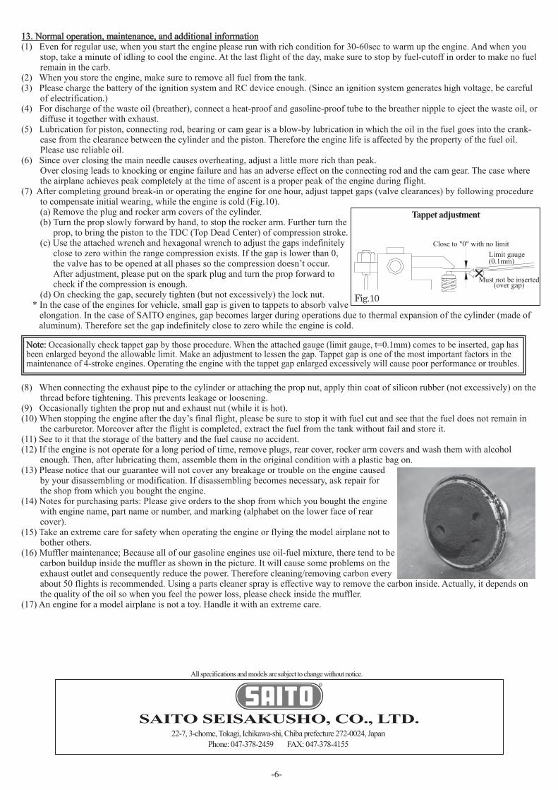
the airplane achieves peak completely at the time of ascent is a proper peak of the engine during flight.(7) After completing ground break-in or operating the engine for one hour, adjust tappet gaps (valve clearances) by following procedure
to compensate initial wearing, while the engine is cold (Fig.10).(a) Remove the plug and rocker arm covers of the cylinder.(b) Turn the prop slowly forward by hand, to stop the rocker arm. Further turn the
prop, to bring the piston to the TDC (Top Dead Center) of compression stroke.(c) Use the attached wrench and hexagonal wrench to adjust the gaps indefinitely
close to zero within the range compression exists. If the gap is lower than 0, the valve has to be opened at all phases so the compression doesn’t occur. After adjustment, please put on the spark plug and turn the prop forward to check if the compression is enough.
(d) On checking the gap, securely tighten (but not excessively) the lock nut.* In the case of the engines for vehicle, small gap is given to tappets to absorb valve elongation. In the case of SAITO engines, gap becomes larger during operations due to thermal expansion of the cylinder (made of
aluminum). Therefore set the gap indefinitely close to zero while the engine is cold.
(8) When connecting the exhaust pipe to the cylinder or attaching the prop nut, apply thin coat of silicon rubber (not excessively) on the thread before tightening. This prevents leakage or loosening.
(9) Occasionally tighten the prop nut and exhaust nut (while it is hot).(10) When stopping the engine after the day’s final flight, please be sure to stop it with fuel cut and see that the fuel does not remain in
the carburetor. Moreover after the flight is completed, extract the fuel from the tank without fail and store it.(11) See to it that the storage of the battery and the fuel cause no accident.(12) If the engine is not operate for a long period of time, remove plugs, rear cover, rocker arm covers and wash them with alcohol
enough. Then, after lubricating them, assemble them in the original condition with a plastic bag on.(13) Please notice that our guarantee will not cover any breakage or trouble on the engine caused
by your disassembling or modification. If disassembling becomes necessary, ask repair for the shop from which you bought the engine.
(14) Notes for purchasing parts: Please give orders to the shop from which you bought the engine with engine name, part name or number, and marking (alphabet on the lower face of rear cover).
(15) Take an extreme care for safety when operating the engine or flying the model airplane not to bother others.
(16) Muffler maintenance; Because all of our gasoline engines use oil-fuel mixture, there tend to be carbon buildup inside the muffler as shown in the picture. It will cause some problems on the exhaust outlet and consequently reduce the power. Therefore cleaning/removing carbon every
about 50 flights is recommended. Using a parts cleaner spray is effective way to remove the carbon inside. Actually, it depends on the quality of the oil so when you feel the power loss, please check inside the muffler.
(17) An engine for a model airplane is not a toy. Handle it with an extreme care.
Note: Occasionally check tappet gap by those procedure. When the attached gauge (limit gauge, t=0.1mm) comes to be inserted, gap has been enlarged beyond the allowable limit. Make an adjustment to lessen the gap. Tappet gap is one of the most important factors in the maintenance of 4-stroke engines. Operating the engine with the tappet gap enlarged excessively will cause poor performance or troubles.

153
153-1
153-3153-4
153-2
SAITO FG-21 Parts ListNo. Description Q'ty No. Description Q'ty
01 Cylinder 1 Valve set (In & Ex)
06 Piston 1 46-1,-2
07 Piston pin 1 Valve spring & Keeper & Retainer
08 Piston pin retainer 2 47-1,-2,48
09 Piston ring 1 48 Valve retainer (Cotter) 2
10 Connecting rod 1 49 Rocker arm cover 2
Cylinder screw set 69 Intake manifold (Intake pipe) 1
14-1,-2 74 Muffler 1
15 Crankcase 1 Muffler manifold set
17 Rear cover (Back plate) 1 75-1,80
19 Breather nipple 1 80 Muffler nut 2
20 Front ball bearing 1 82-1 Carburetor complete 1set
22 Rear ball bearing 1 Carburetor body assembly
23 Crankshaft 1 82-1-1,-1-2,-1-3,-1-4,-1-7,-1-8,-1-13,-1-14
Taper collet & Drive flange -1-15,-1-27,-1-28,32-5,91-1
27-1,-2 85 Full throttle needle 1
Prop washer & Nut Throttle barrel assembly
28-1,-2 82-1-5,-1-9,88B,89
Crankcase screw set Throttle lever
31-1,-2,-3 88B,90-1
Engine gasket set 89 Idle needle 1
32-1,-2,-3,-4,-5,-6,-8 Carburetor screw & spring set
33 Cam gear housing 1 82-1-7,-1-8,-1-13,-1-16,-1-26,-1-28,90-1
35 Cam gear 1 Carburetor gasket set
36A Cam gear shaft 1 32-4,-5,-6,82-1-9,-1-14,-1-18,-1-20,-1-22,91-1
37 Steel washer set 1set Engine mount set
38 Tappet 1 95-1,-2,-3,-4,-5,-6
39 Pushrod 1 110 Anti loosening nut 1
Pushrod cover & Rubber seal 152 Screw-pin (For drive flange setting) 1
40-1,-2,-3 Electronic ignition system
41 Rocker arm 1 153-1,-2,-3,-4,-5
Rocker arm screw & Nut Pump assembly
42-1,42-2 82-1-17,-1-18,-1-19,-1-20,-1-21,-1-22,-1-23
43 Rocker arm pin 2 -1-24,-1-25,-1-26
14
27
28
31
32
40
42
1set
1ea.
1ea.
1set
1set
2ea.
2ea.
95
153
1set
87
88B
90
1
91
46 1set
47 2ea.
160
1set
1set
1set
1set
1set
1set
1set
75
83-1